


Investigation into the Potential Use of Damping Plates in a Spar-Type Floating Offshore Wind Turbine


Abstract
:1. Introduction
2. Experiment
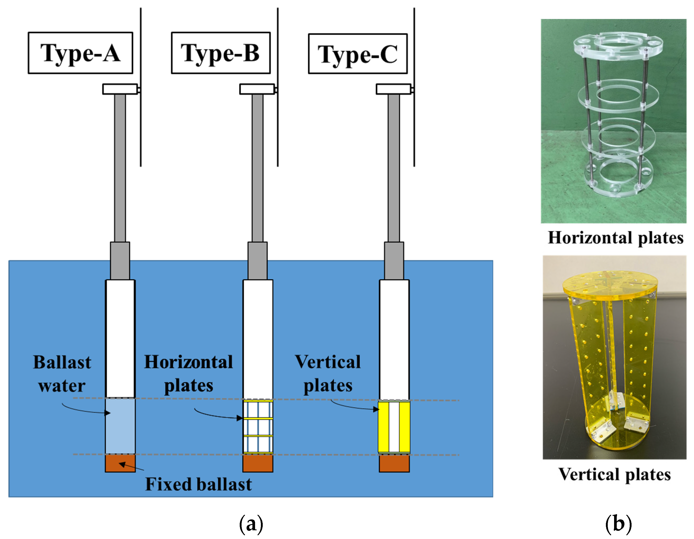
2.1. Spar Models
2.2. Rotor Model
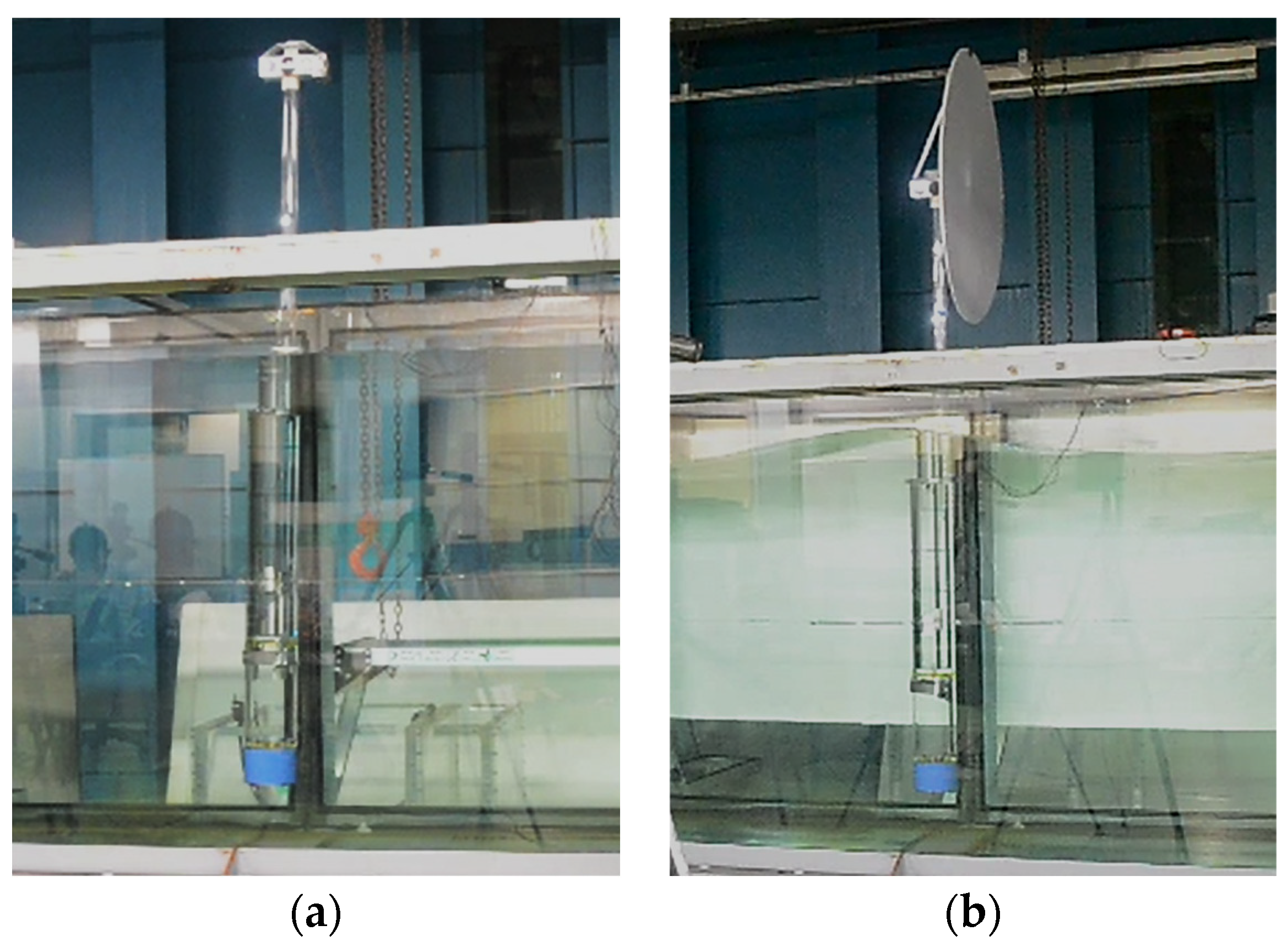
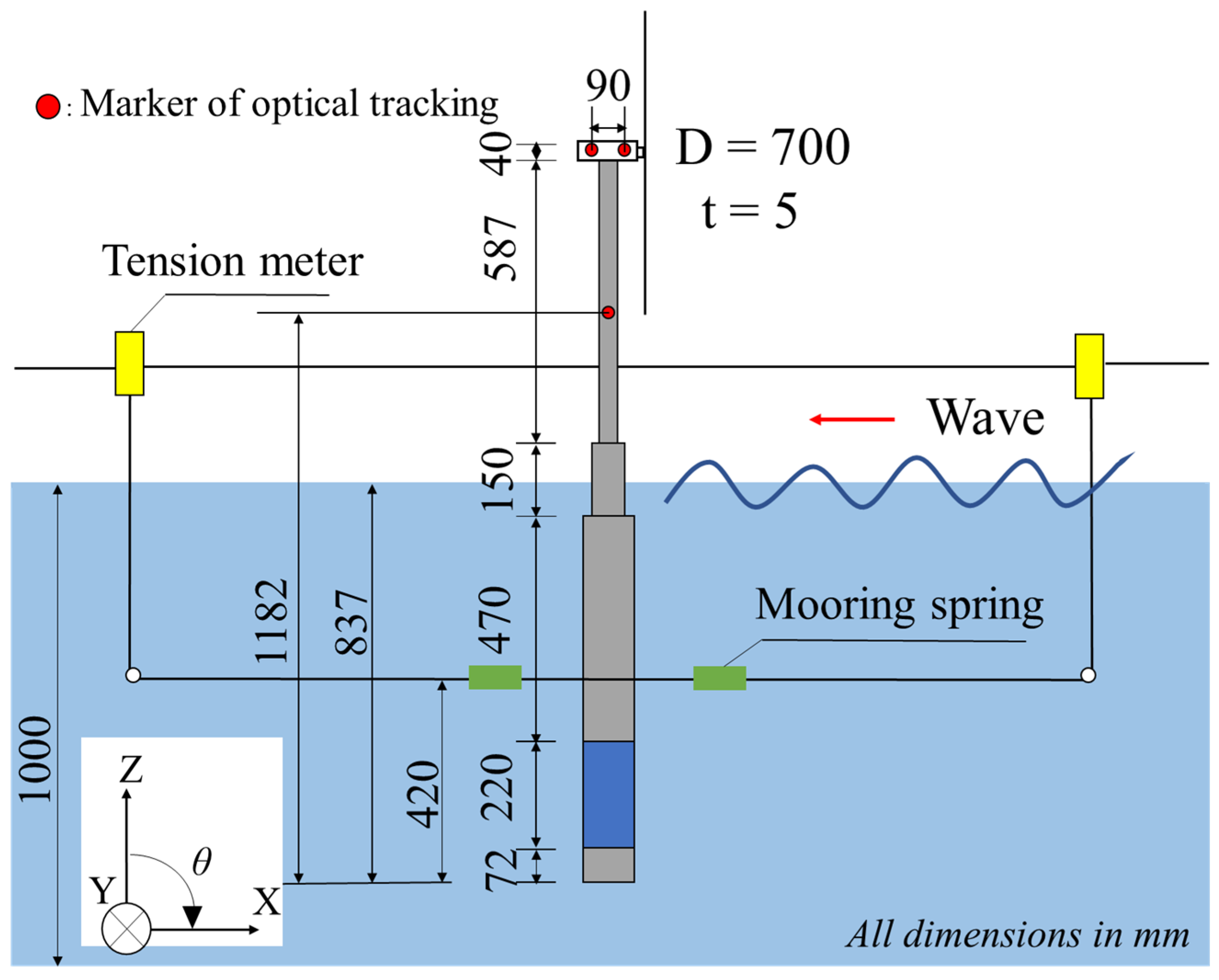
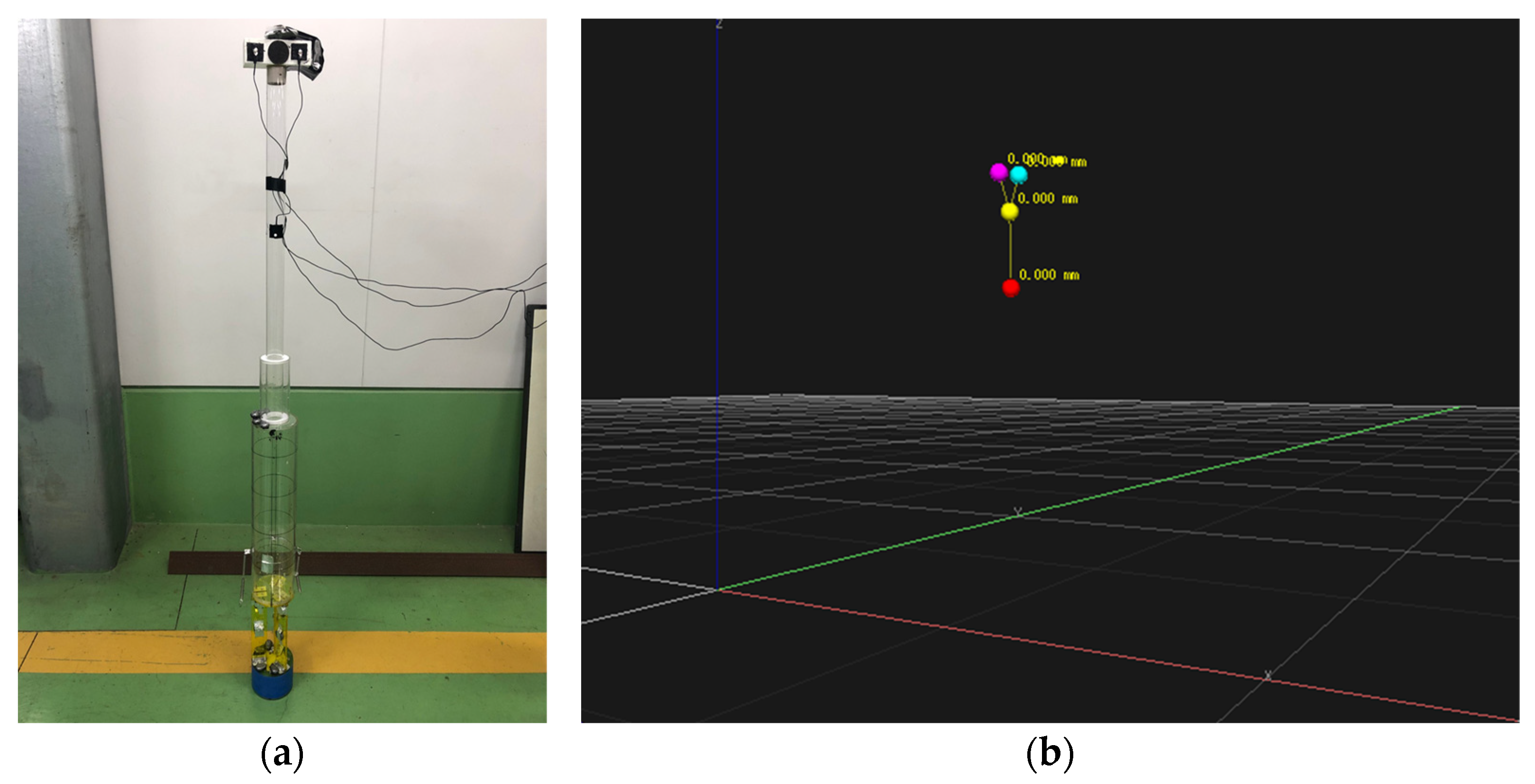
2.3. Experiment Setup and Conditions
2.4. Spar Motion Characteristics in Waves
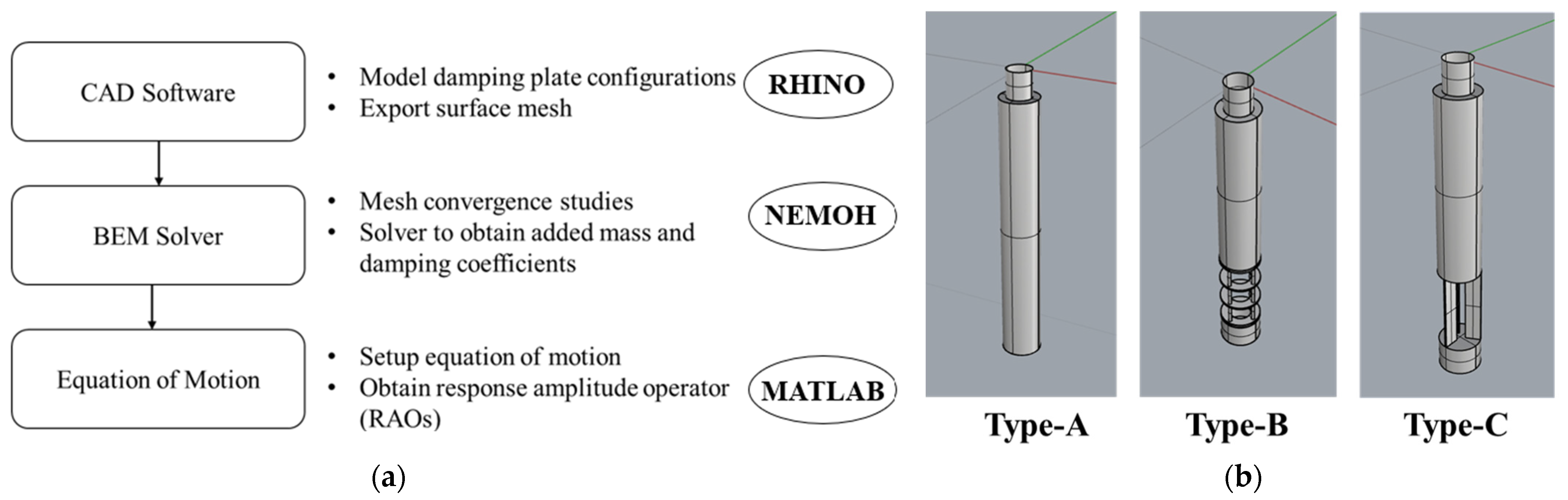
3. Calculation Methodology
3.1. Calculation Technique
3.2. Equation of Motion
3.3. Modeling of Wind Drag Force Due to Disk
4. Results and Discussion
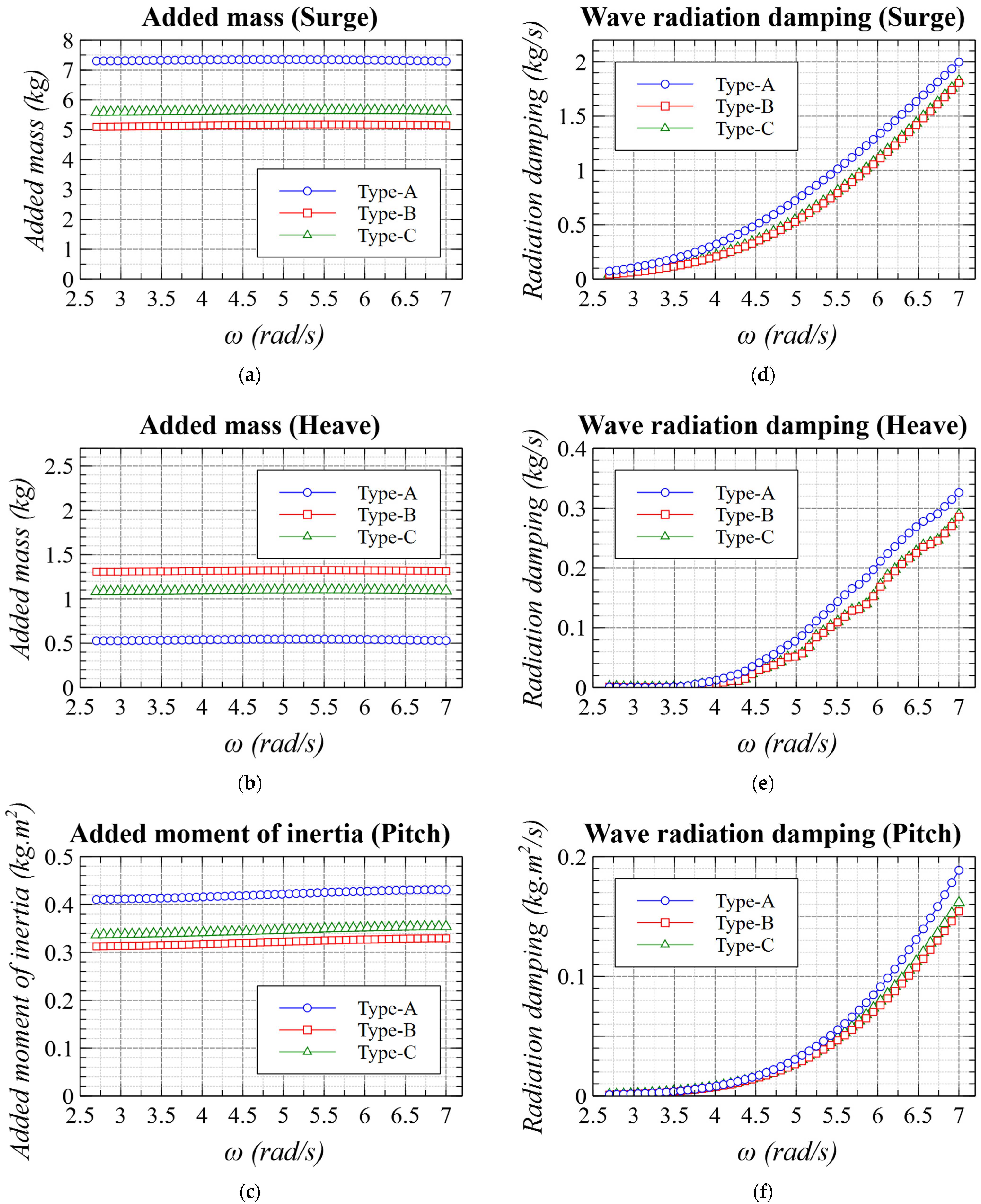
4.1. Added Mass and Wave Radiation Damping
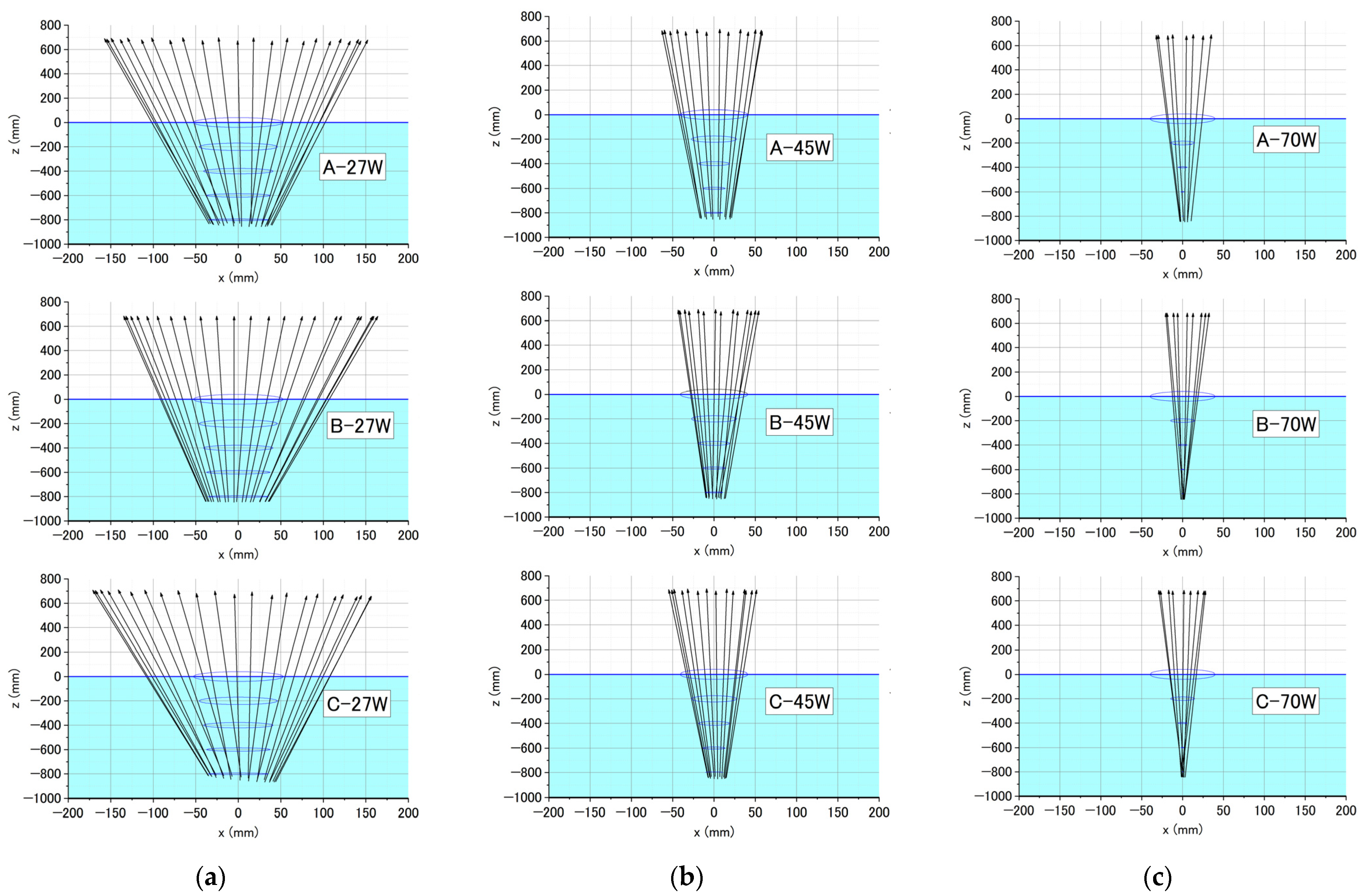
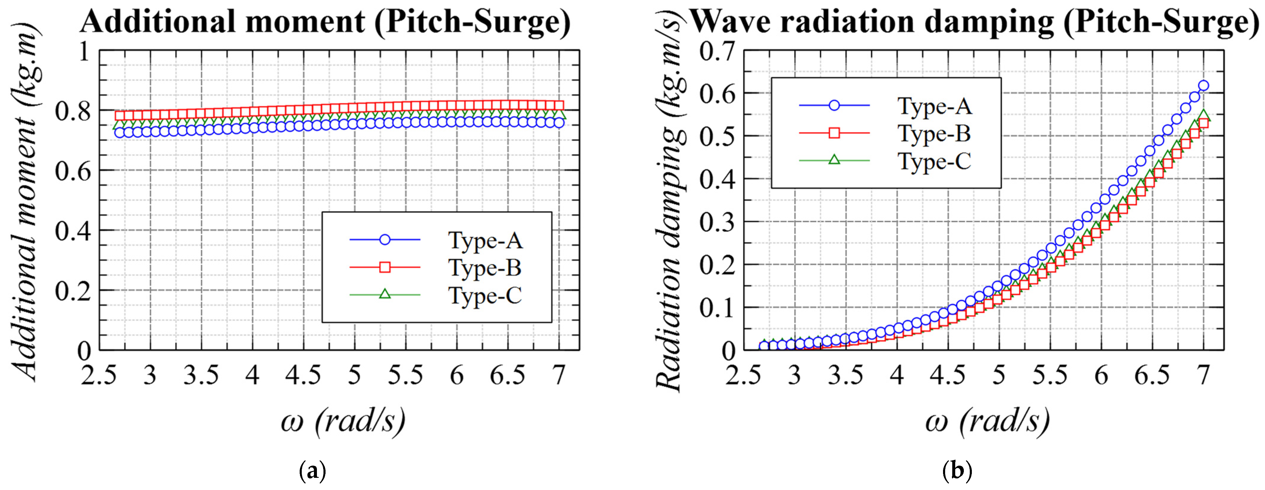
4.2. Pitch–Surge Coupling Effects
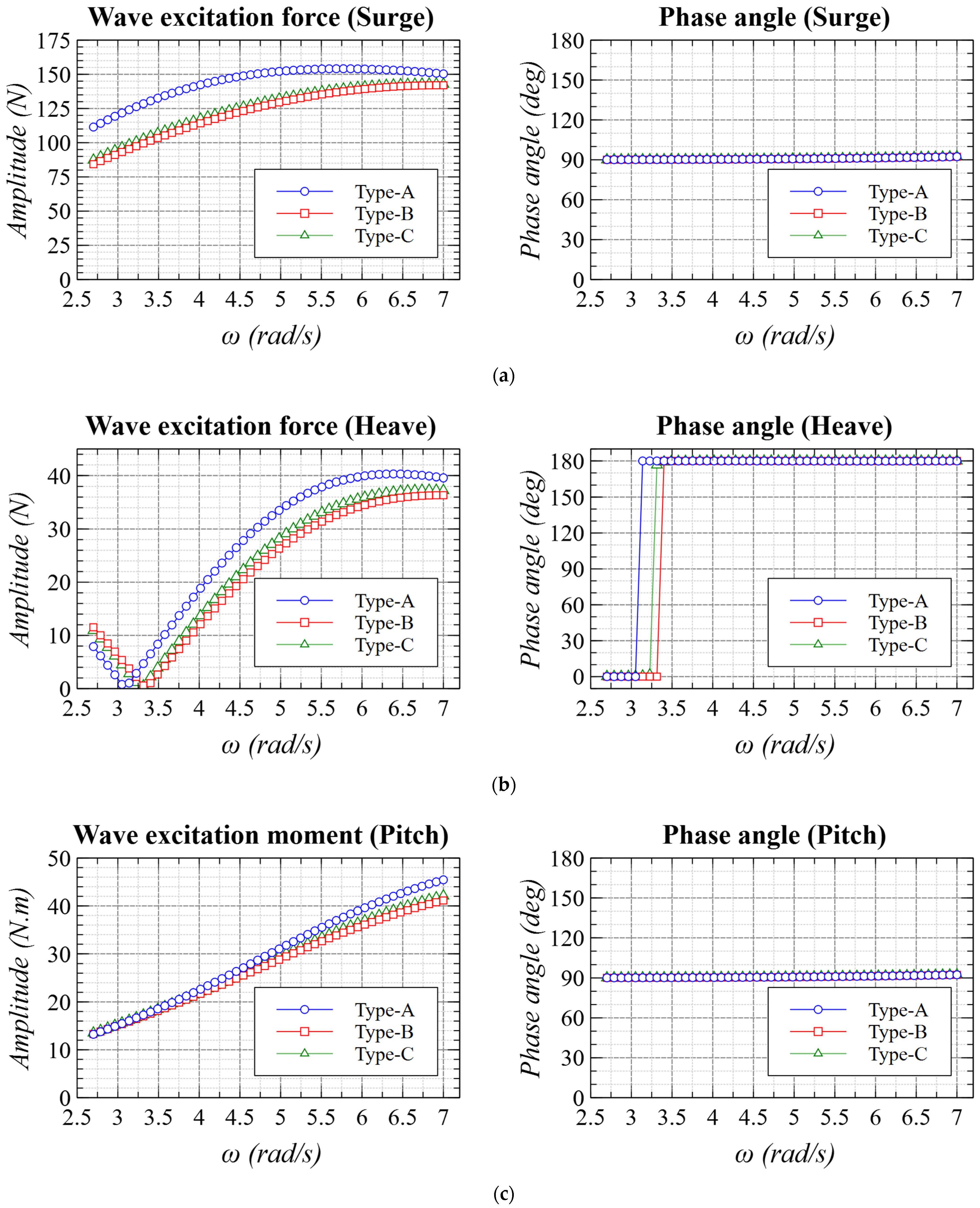
4.3. Wave Excitation Force
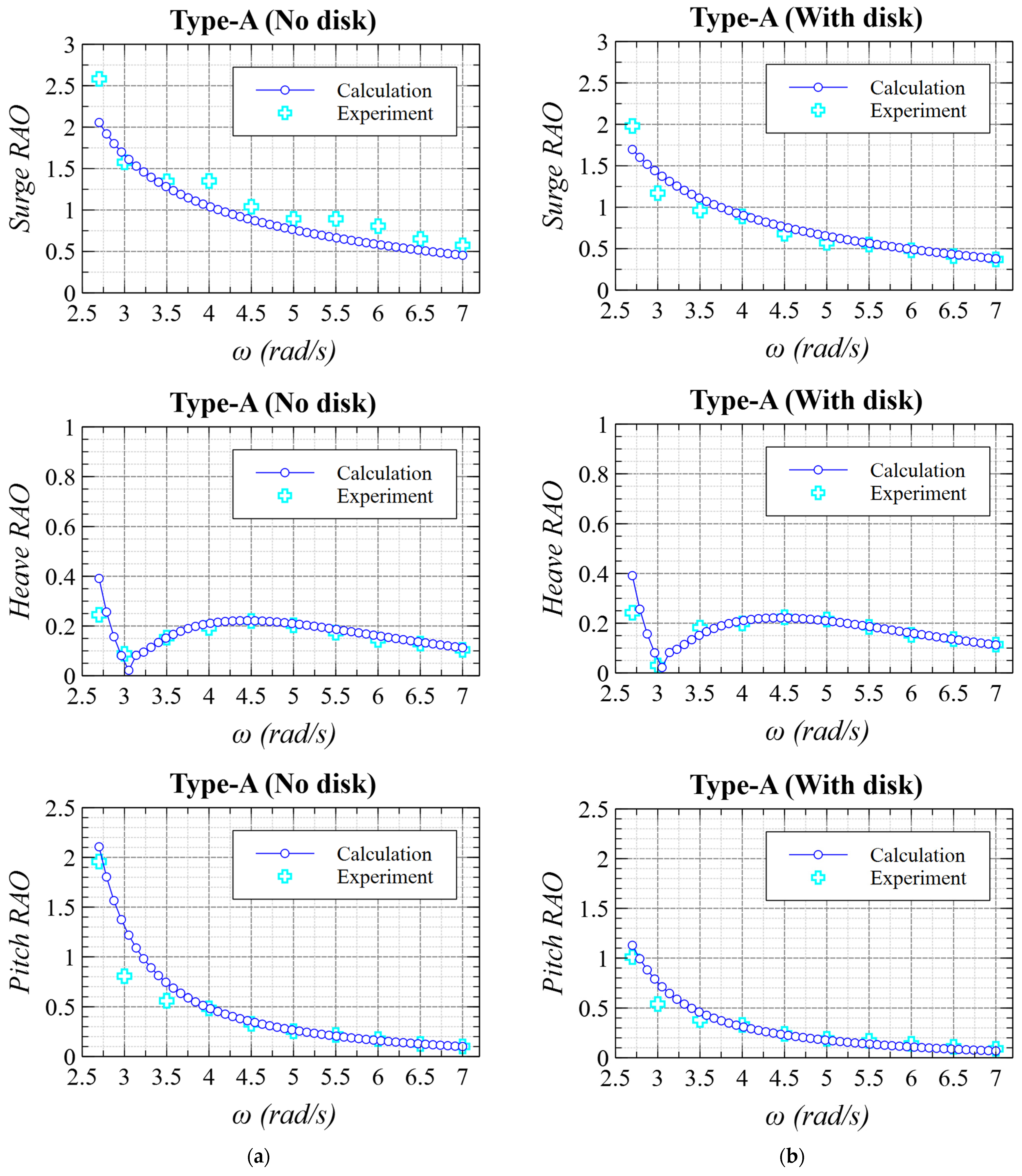
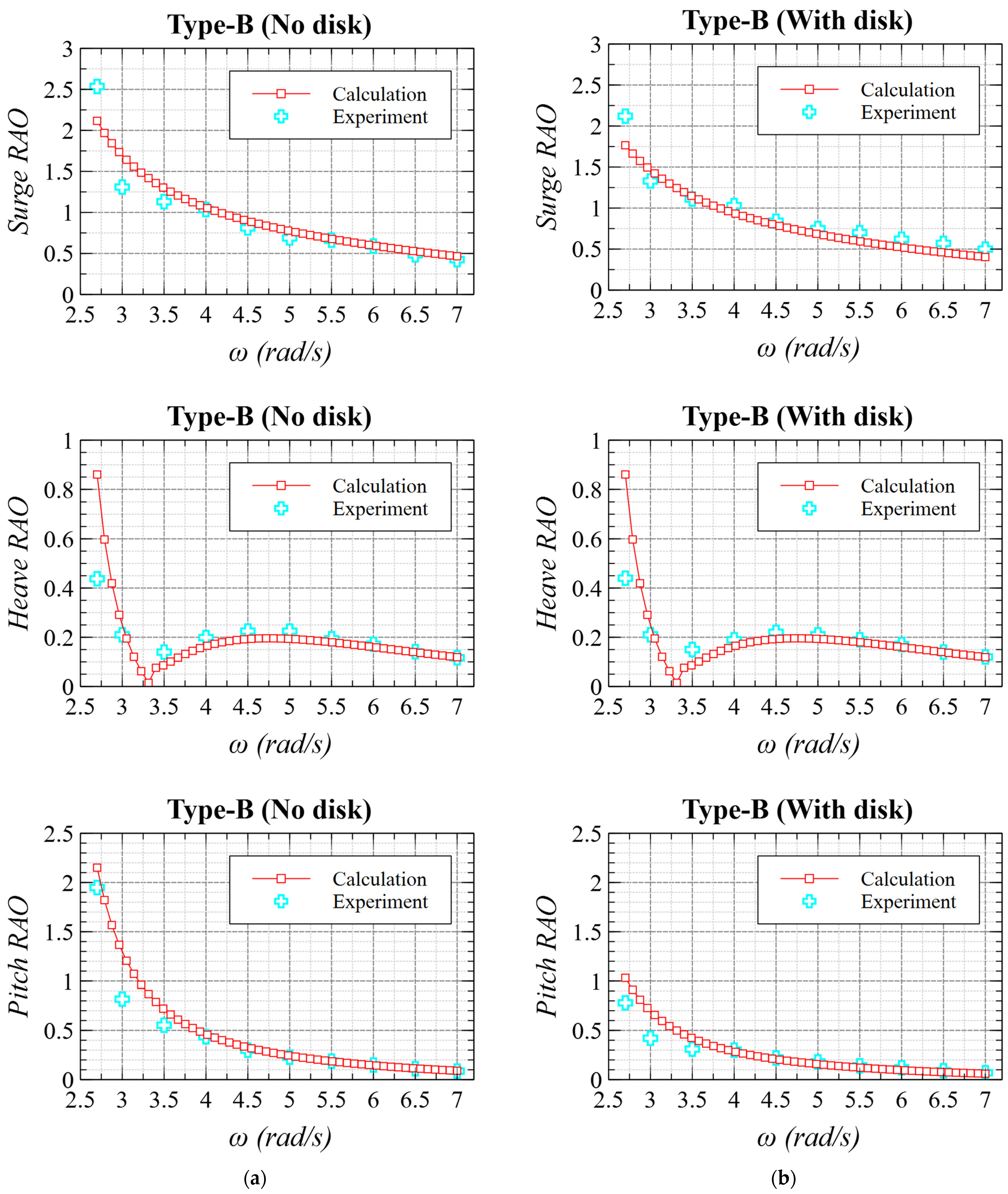
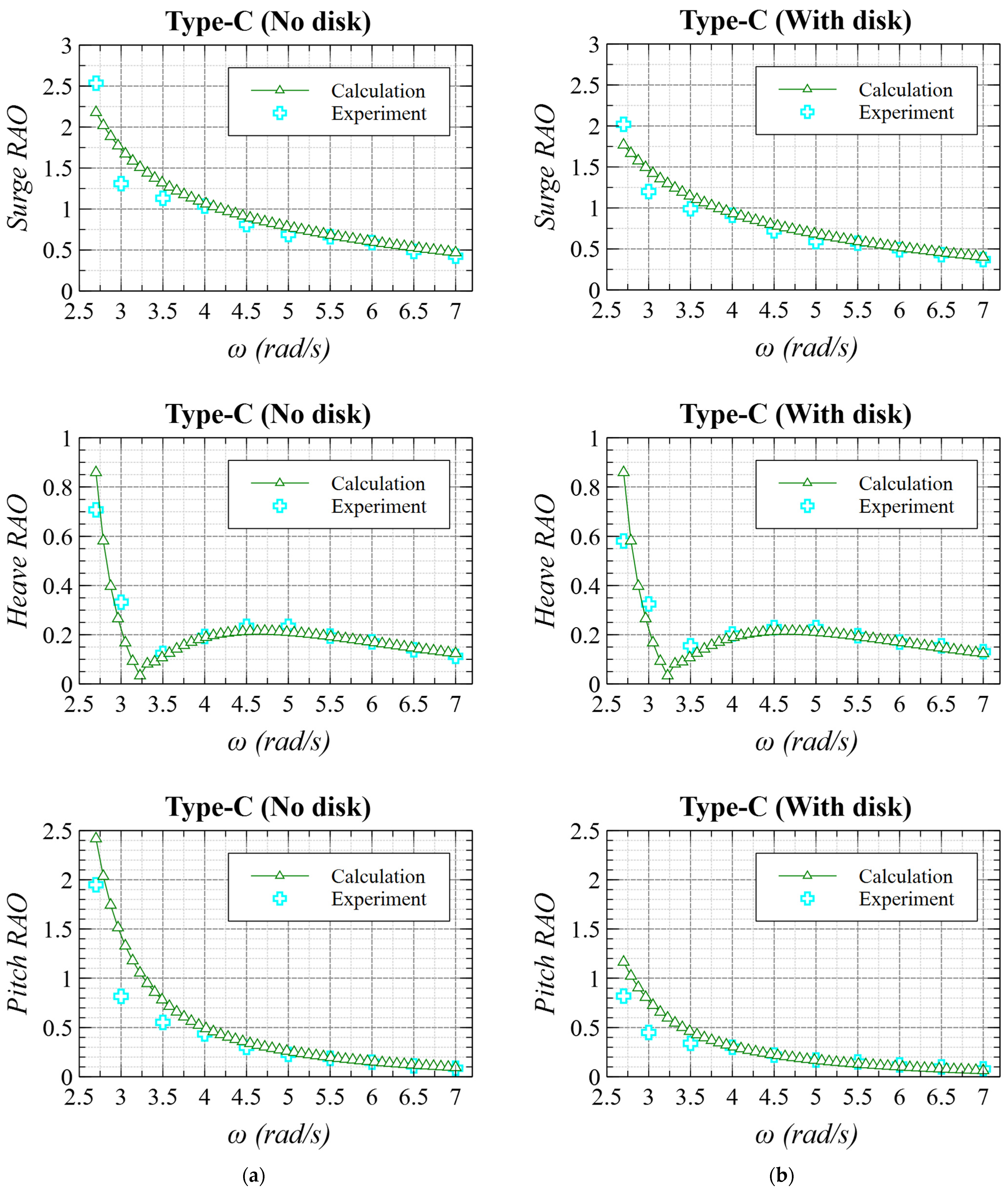
4.4. Motion Response of Spar Models—Validation
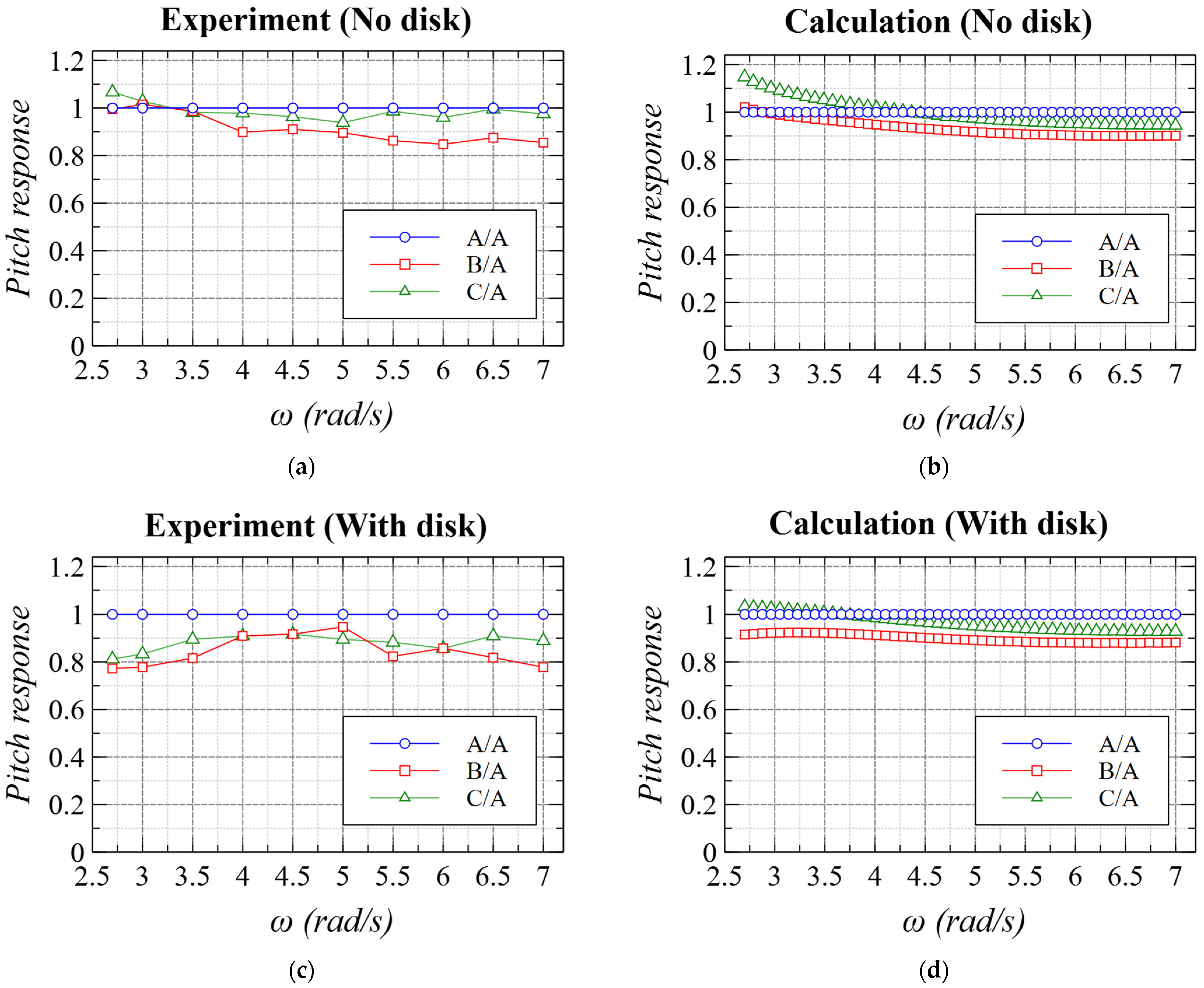
4.5. Effect of Damping Plates on Pitch Response
5. Conclusions
- Characteristic motions of spar in waves are presented. The center of rotation was low in wide wave frequencies; mostly lower than the bottom of the floater because surge and pitch motions were in phase. This can be explained by the congruence of phases of wave exciting force/moment in surge and pitch directions.
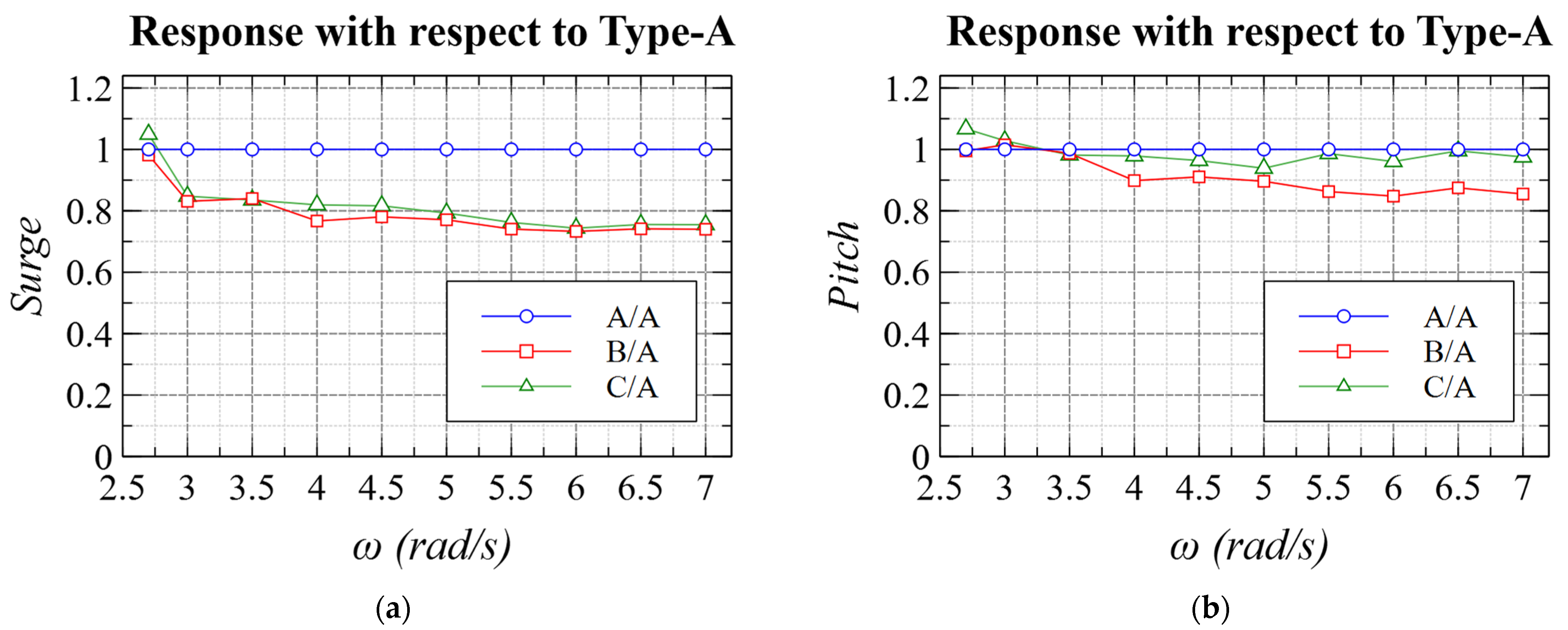
- Among 6DOF motions, pitch is generally considered the most important for FOWT not only on power generation but bending moment at the tower root. Focusing on pitch motions in regular waves, RAOs of the proposed spar types (Types-B and C) were smaller than the conventional type (Type-A) in most wave frequencies.
- Comparing proposed spar types with the conventional type, the moment of inertia and the added moment of inertia were smaller and wave exciting moments were almost the same amplitude. These quantities lead to larger pitch motion. However, as for pitch–surge coupling, the coupling coefficients were almost the same among the three types and the surge amplitudes of the proposed types were significantly smaller than the conventional type. From this comparison, it was found that the reformed ballast parts work to reduce pitch motion through pitch–surge coupling.
- It is concluded from the validation results that the proposed calculation methodology by potential theory can be used to incorporate the effect of damping plates in spar platforms. It is considered that this approach is useful when flow separation at the plates is limited due to small relative water velocity. This kind of methodology and hydrodynamic considerations can help find new geometries of floating structures of wind turbines.
Author Contributions
Funding
Institutional Review Board Statement
Informed Consent Statement
Data Availability Statement
Acknowledgments
Conflicts of Interest
References
- Lu, X.; McElroy, M.B.; Kiviluoma, J. Global potential for wind-generated electricity. Proc. Natl. Acad. Sci. USA 2009, 106, 10933–10938. [Google Scholar] [CrossRef]
- Esteban, M.D.; Diez, J.J.; López, J.S.; Negro, V. Why offshore wind energy? Renew. Energy 2011, 36, 444–450. [Google Scholar] [CrossRef]
- Barooni, M.; Ashuri, T.; Sogut, D.V.; Wood, S.; Taleghani, S.G. Floating Offshore Wind Turbines: Current Status and Future Prospects. Energies 2023, 16, 2. [Google Scholar] [CrossRef]
- Ghigo, A.; Cottura, L.; Caradonna, R.; Bracco, G.; Mattiazzo, G. Platform Optimization and Cost Analysis in a Floating Offshore Wind Farm. J. Mar. Sci. Eng. 2020, 8, 835. [Google Scholar] [CrossRef]
- Edwards, E.C.; Holcombe, A.; Brown, S.; Ransley, E.; Hann, M.; Greaves, D. Evolution of floating offshore wind platforms: A review of at-sea devices. Renew. Sustain. Energy Rev. 2023, 183, 113416. [Google Scholar] [CrossRef]
- Tran, T.-T.; Kim, D.-H. The platform pitching motion of floating offshore wind turbine: A preliminary unsteady aerodynamic analysis. J. Wind Eng. Ind. Aerodyn. 2015, 142, 65–81. [Google Scholar] [CrossRef]
- Wu, C.-H.K.; Nguyen, V.-T. Aerodynamic simulations of offshore floating wind turbine in platform-induced pitching motion. Wind Energy 2017, 20, 835–858. [Google Scholar] [CrossRef]
- Cottura, L.; Caradonna, R.; Novo, R.; Ghigo, A.; Bracco, G.; Mattiazzo, G. Effect of pitching motion on production in a OFWT. J. Ocean Eng. Mar. Energy 2022, 8, 319–330. [Google Scholar] [CrossRef]
- Srinivasamurthy, S.; Iwamatsu, S.; Hashimoto, K.; Suzuki, H.; Chujo, T.; Haneda, K.; Nihei, Y. Study of slow-drifting damping on wind tracking performance of a new-type FOWT ‘Optiflow’ with single-point mooring. Ocean Eng. 2021, 242, 110131. [Google Scholar] [CrossRef]
- Nihei, Y.; Srinivasamurthy, S.; Hashimoto, K.; Iijima, K. Influence of slow-drifting damping on weathervaning of single-point moored floating offshore wind turbines. Ocean Eng. 2020, 217, 107899. [Google Scholar] [CrossRef]
- Srinivasamurthy, S.; Iijima, K.; Fujikubo, M.; Nihei, Y. Elastic-plastic behavior analysis for a flexible FOWT subjected to blade pitch control malfunction. J. Jpn. Soc. Nav. Archit. Ocean Eng. 2016, 23, 179–187. [Google Scholar] [CrossRef]
- Srinivasamurthy, S.; Iijima, K.; Nihei, Y.; Hara, N. Coupled simulation between FAST and Hydro-structural code for a flexible FOWT considering blade pitch control malfunction. In Proceedings of the 35th International Conference on Ocean, Offshore and Arctic Engineering (ASME 2016), Busan, Republic of Korea, 19–24 June 2016. [Google Scholar] [CrossRef]
- Hywind Spar, Scotland. Available online: https://www.equinor.com/energy/hywind-scotland (accessed on 22 May 2024).
- Xu, X.; Srinil, N. Dynamic response analysis of spar-type floating wind turbines and mooring lines with uncoupled vs. coupled models. In Proceedings of the 34th International Conference on Ocean, Offshore and Arctic Engineering (ASME 2015), St. John’s, NL, Canada, 31 May–5 June 2016. [Google Scholar] [CrossRef]
- Jonkman, J. Definition of the Floating System for Phase IV of OC3; Technical Report; No. NREL/TP-500-47535; National Renewable Energy Lab. (NREL): Golden, CO, USA, 2010. Available online: https://www.nrel.gov/docs/fy10osti/47535.pdf (accessed on 22 May 2024).
- Goto Island Hybrid Spar, Japan. Available online: https://haenkaze.com/en/ (accessed on 22 May 2024).
- Utsunomiya, T.; Sato, I.; Kobayashi, O.; Shiraishi, T.; Harada, T. Design and installation of a hybrid-spar floating wind turbine platform. In Proceedings of the 34th International Conference on Ocean, Offshore and Arctic Engineering (ASME 2015), St. John’s, NL, Canada, 31 May–5 June 2016. [Google Scholar] [CrossRef]
- Tanaka, K.; Iwamoto, A.; Utsunomiya, T. Comparison of dynamic response of a 2-MW hybrid-spar floating offshore wind turbine during power production using full-scale field data. In Proceedings of the Grand Renewable Energy 2022 International Conference, Tokyo, Japan, 13–20 December 2022. [Google Scholar] [CrossRef]
- Subbulakshmi, A.; Sundaravadivelu, R. Effects of damping plate position on heave and pitch responses of spar platform with single and double damping plates under regular waves. Ocean Eng. 2021, 224, 108719. [Google Scholar] [CrossRef]
- Rao, M.J.; Nallayarasu, S.; Bhattacharyya, S.K. CFD approach to heave damping of spar with heave plates with experimental validation. Appl. Ocean Res. 2021, 108, 102517. [Google Scholar] [CrossRef]
- Subbulakshmi, A.; Jithin, J.; Sundaravadivelu, R.; Selvam, R.P. Effect of viscous damping on hydrodynamic response of spar with heave plate. Aquat. Procedia 2015, 4, 508–515. [Google Scholar] [CrossRef]
- Takata, T.; Takaoka, M.; Houtani, H.; Hara, K.; Oh, S.; Malta, E.B.; Iijima, K.; Suzuki, H.; Gonçalves, R.T. Effect of Heave Plates on the Wave Motion of a Flexible Multicolumn FOWT. Energies 2022, 15, 7605. [Google Scholar] [CrossRef]
- Wang, W.; Zhao, C.; Jia, P.; Lu, Z.; Xie, Y. Numerical simulation and experimental study on perforated heave plate of a DeepCwind floating wind turbine platform. Ships Offshore Struct. 2023, 18, 438–449. [Google Scholar] [CrossRef]
- Zhang, L.; Shi, W.; Zeng, Y.; Michailides, C.; Zheng, S.; Li, Y. Experimental investigation on the hydrodynamic effects of heave plates used in floating offshore wind turbines. Ocean Eng. 2023, 267, 113103. [Google Scholar] [CrossRef]
- Turner, M.; Wang, L.; Thiagarajan, K.; Robertson, A. Heave plate hydrodynamic coefficients for floating offshore wind turbines—A compilation of data. In Proceedings of the 5th International Offshore Wind Technical Conference (ASME 2023), Exeter, UK, 18–19 December 2023. [Google Scholar] [CrossRef]
- Bangs, A.S.; Miettinen, J.A.; Silvola, I.; Mikkola, T.P.J.; Beattie, S.M. Design of the truss spars for the Nansen/Boomvang field development. In Proceedings of the Offshore Technology Conference, Houston, TX, USA, 6–9 May 2002. [Google Scholar] [CrossRef]
- Wang, B.W.; Choi, E.J.; Jung, S.; Park, S. Hydrodynamic response of alternative floating substructures for spar-type offshore wind turbines. In Proceedings of the Advances in Civil, Environmental, and Materials Research (ACEM’ 12), Seoul, Republic of Korea, 26–30 August 2012. [Google Scholar]
- Ishida, S.; Imai, Y. New spar design for floating offshore wind turbine with damping plates. In Proceedings of the 38th International Conference on Ocean, Offshore and Arctic Engineering (ASME 2019), Glasgow, UK, 9–14 June 2019. [Google Scholar] [CrossRef]
- Jonkman, J.; Butterfield, S.; Musial, W.; Scott, G. Definition of a 5-MW Reference Wind Turbine for Offshore System Development; Technical Report; No. NREL/TP-500-38060; National Renewable Energy Lab. (NREL): Golden, CO, USA, 2009. Available online: https://www.nrel.gov/docs/fy09osti/38060.pdf (accessed on 22 May 2024).
- Bergua, R.; Wiley, W.; Robertson, A.; Jonkman, J.; Brun, C.; Pineau, J.P.; Qian, Q.; Maoshi, W.; Beardsell, A.; Cutler, J.; et al. OC6 project Phase IV: Validation of numerical models for novel floating offshore wind support structures. Wind Energy Sci. 2024, 9, 1025–1051. [Google Scholar] [CrossRef]
- Rhino CAD Software. Available online: https://www.rhino3d.com/ (accessed on 22 May 2024).
- NEMOH Open-Source BEM Software. Available online: https://lheea.ec-nantes.fr/valorisation/logiciels-et-brevets/nemoh-presentation (accessed on 22 May 2024).
- Babarit, A.; Delhommeau, G. Theoretical and numerical aspects of the open source BEM solver NEMOH. In Proceedings of the 11th European Wave and Tidal Energy Conference (EWTEC2015), Nantes, France, 6–11 September 2015. [Google Scholar]
- Kurnia, R.; Ducrozet, G. Computation of second-order wave loads on floating offshore wind turbine platforms in bi-chromatic bi-directional waves using open-source potential flow solver NEMOH. In Proceedings of the 18èmes Journées de l’Hydrodynamique, Poitiers, France, 22–24 November 2022; Available online: https://jh2022.sciencesconf.org/420480/document (accessed on 22 May 2024).
- Kurnia, R.; Ducrozet, G.; Gilloteaux, J.-C. Second order difference- and sum-frequency wave loads in the open-source potential flow solver NEMOH. In Proceedings of the 41st International Conference on Ocean, Offshore and Arctic Engineering (ASME 2022), Hamburg, Germany, 5–10 June 2022. [Google Scholar] [CrossRef]

| Spar Model Specification (Scale: 1/120) | Type-A | Type-B | Type-C | |
|---|---|---|---|---|
| Diameter of the main part (m) | 0.11 | |||
| Diameter of the water plane (m) | 0.07 | |||
| Diameter of the tower (m) | 0.04 | |||
| Draft (m) | 0.845 | |||
| Mass (kg) | 7.49 | 5.71 | 5.84 | |
| Pitch moment of inertia (kgm2) | 1.27 | 1.23 | 1.25 | |
| Metacentric height, GM (m) | 0.084 | 0.114 | 0.112 | |
| Stability parameter, weight × GM (Nm) | 6.17 | 6.39 | 6.42 | |
| Keel to center of gravity, KG (m) | 0.308 | 0.345 | 0.337 | |
| Heave natural period (s) | No disk | 2.79 | 2.62 | 2.56 |
| With disk | ||||
| Pitch natural period (s) | No disk | 3.16 | 2.97 | 3.05 |
| With disk | 3.37 | 3.77 | 3.23 | |
Disclaimer/Publisher’s Note: The statements, opinions and data contained in all publications are solely those of the individual author(s) and contributor(s) and not of MDPI and/or the editor(s). MDPI and/or the editor(s) disclaim responsibility for any injury to people or property resulting from any ideas, methods, instructions or products referred to in the content. |
© 2024 by the authors. Licensee MDPI, Basel, Switzerland. This article is an open access article distributed under the terms and conditions of the Creative Commons Attribution (CC BY) license (https://creativecommons.org/licenses/by/4.0/).
Share and Cite
Srinivasamurthy, S.; Ishida, S.; Yoshida, S. Investigation into the Potential Use of Damping Plates in a Spar-Type Floating Offshore Wind Turbine. J. Mar. Sci. Eng. 2024, 12, 1071. https://doi.org/10.3390/jmse12071071
Srinivasamurthy S, Ishida S, Yoshida S. Investigation into the Potential Use of Damping Plates in a Spar-Type Floating Offshore Wind Turbine. Journal of Marine Science and Engineering. 2024; 12(7):1071. https://doi.org/10.3390/jmse12071071
Chicago/Turabian StyleSrinivasamurthy, Sharath, Shigesuke Ishida, and Shigeo Yoshida. 2024. "Investigation into the Potential Use of Damping Plates in a Spar-Type Floating Offshore Wind Turbine" Journal of Marine Science and Engineering 12, no. 7: 1071. https://doi.org/10.3390/jmse12071071
APA StyleSrinivasamurthy, S., Ishida, S., & Yoshida, S. (2024). Investigation into the Potential Use of Damping Plates in a Spar-Type Floating Offshore Wind Turbine. Journal of Marine Science and Engineering, 12(7), 1071. https://doi.org/10.3390/jmse12071071