Article

Container Yard Layout Design Problem with an Underground Logistics System

1
Shanghai Municipal Engineering Design Institute (Group) Co., Ltd., 901 North Zhongshan Road (2nd), Yangpu District, Shanghai 200092, China
2
Institute of Logistics Science and Engineering, Shanghai Maritime University, 1550 Haigang Avenue, Pudong District, Shanghai 201306, China
*
Author to whom correspondence should be addressed.
J. Mar. Sci. Eng. 2024, 12(7), 1103; https://doi.org/10.3390/jmse12071103
Submission received: 24 May 2024 / Revised: 24 June 2024 / Accepted: 26 June 2024 / Published: 28 June 2024
(This article belongs to the Section Ocean Engineering)

Abstract

:
In recent years, underground logistics systems have attracted more and more attention from scholars and are considered to be a promising new green and intelligent transportation mode. This paper proposes a yard design problem considering an underground container logistics system. The structure and workflow of the underground container logistics system are analyzed, and key features are recognized for the yard design problem, such as the container block layout direction, the lane configuration in the yard, and the number of container blocks. We formulate the problem into mathematical models under different scenarios of the key features with the comprehensive objective of maximizing the total throughput and minimizing the total operation cost simultaneously. An improved tabu search algorithm is designed to solve the problem. Experimental results show that the proposed algorithm can generate a satisfactory layout design solution for a real-size instance. Our research studies different container yard design options for introducing the underground logistics system into port terminals, which provides an important scientific foundation for promoting the application of underground container logistics systems.

1. Introduction

In recent years, with the rapid development of the global economy, the scales and throughputs of container ports have grown continuously. Contradictions are increasing between the expansion of container ports and the development of port cities in terms of space, resources, and environment. In particular, thousands of trucks traveling through the port city every day to collect the containers from or to the port increase the traffic pressure in the city sharply. The heavy traffic of container trucks intensifies the congestion and air pollution in the port cities. More yard area is also required to match the growing throughput of large ports, which is quite difficult for major cities since land resources are limited and expensive [1,2,3,4,5,6].
To alleviate the above-mentioned conflicts between the ports and cities, container ports always look for more efficient, intelligent, and environmentally friendly operational methods. The underground logistics system with automatic control is a relatively new mode of cargo transportation that is considered to be more efficient and less polluted [7,8,9,10]. We consider an underground container logistics system proposed by Liang et al. (2022) [11], where a suburban logistics park and a container port are connected by a deep underground tunnel. Figure 1 shows the basic structure of the underground container logistics system. There is a vertical shaft in the logistics park and the port terminal yard, respectively. The import containers, for example, are unloaded from a ship and transported by internal trucks directly to the shaft’s entrance or will be transported from the above-ground container yard to the shaft after a temporary storage period. A gantry crane over the shaft loads the containers vertically from the trucks to underground logistics vehicles (ULVs). The ULVs travel in the deep underground tunnel to transport the containers from the terminal to the logistics park, and the containers will be unloaded through the shaft in the logistics park from the ULVs to the trucks. The process is going in the opposite direction for the export containers. This logistics system transfers as much traffic as possible from the surface to the underground, which can not only reduce the traffic problems in the port city but also control the expansion of the port yard by improving the handling efficiency [12,13,14].
The detailed design and operational scheme affect the implementation of the underground container logistics system in practice, but related research is still in its infancy. Some scholars have carried on the concept design of the underground container logistics system and the selection and operation of the equipment for the system [15,16,17,18]. To the best of our knowledge, there is a lack of studies focused on the layout of the container yard with an underground logistics system. The yard handles the storage of import and export containers, which is the connection between the complex operations of the external trucks or ships and the operations at the shaft and in the underground tunnel. The layout of the yard directly influences the operations of the internal trucks and the gantry crane of the shaft. Improving the layout of the container yard, including the vertical shaft with the gantry crane, is the foundation for achieving efficient operation of the entire system.
Thus, this paper studies the layout design problem of the container yard with an underground logistics system, considering the overall system throughput and operating costs. Three features are analyzed, including container stacking direction, lane configuration, and the number of blocks. Mathematical models are proposed for multiple scenarios based on the features, and an improved forbidden search algorithm is designed to solve the problem. Our results provide a quantitative criterion for container yard design with the underground logistics system, which is significant in promoting the implementation of such a system in practice. The proposed models and algorithm can be generalized to related yard planning problems with other transportation channels.
The rest of this paper is organized as follows: Section 2 is the related literature review. Section 3 describes the operations flow of the underground container logistics system and the container yard layout problem precisely. Section 4 presents the formulations for the yard layout problem. Section 5 designs an improved forbidden search algorithm to solve the problem. Section 6 concludes the paper.

2. Literature Review

This section summarizes the state-of-the-art research in two related areas: the studies on underground container logistics systems and those on the planning and design of container yards.
Only a handful of scholars have studied underground container logistics systems. Early studies focus on the system design point of view, considering construction and reliability. Vernimmen et al. [19] analyzed the feasibility of the construction of an underground container transport system in the port of Andean Weeping and designed a new underground container transport system for both sides of the Celtic River. Fan et al. [20] realized the connection between the underground logistics system and the port by establishing a port-convergence station. A robust optimization model was established to determine the suitable location of the port-confluence station, and the proposed system was verified by simulation.
There are some studies that have considered the operations of container terminals with an underground logistics system. Rezaeifar et al. [21] developed a framework to optimize the capacity of multimodal underground logistics transport terminals through a discrete event simulation model. Chen et al. [10] took Shanghai Yangshan Port as an example, comprehensively considered the total cost of transportation, transportation time, and carbon emissions, and established a multi-objective planning model for the integrated underground and above-ground transportation network. Pan et al. [22] designed an underground container transportation system and established a two-stage model, where the first stage is a 0–1 planning model used to determine the transportation cost of individual containers, and the second stage is a simulation model of the volume of transported containers at a specific time. Liang et al. [11] investigated a novel loading and unloading scheme to optimize the underground container logistics system as well as the configuration and scheduling of underground logistics vehicles and Automated Guided Vehicles (AGVs), among others. Gao et al. [23] used an adaptive genetic algorithm to describe and solve a mixed-integer planning problem to minimize the total time to handle all containers in the Underground Container Logistics System (UCLS). This approach yields a reasonable number of yard trucks for scheduling between loading and unloading points and yards in the UCLS.
Container yard layout and design problems for traditional terminals are widely researched. Most scholars study the layout design of the yard from two aspects: container block planning and resource allocation. Container block planning refers to the study of the size, layout, and space of the container blocks in the yard. Kim et al. [24] calculate the influence of parallel and vertical layouts on the transportation distance of container trucks by judging the traveling path of container trucks in the yards. Abu Aisha et al. [25] proposed a new layout for container terminals in seaports to reduce costs and emissions from port operations. The proposed layout can improve the sustainability of port operations by reducing the distance between berths and interface points and avoiding double handling. Taner et al. [26] developed various simulation models of man-made container terminals and evaluated the performance of the terminals in different scenarios under these models. They found that terminal performance is affected by its layout format. Wiese et al. [27] focused on a particular type of layout for container yards, i.e., yard layout with transfer lanes. They proposed an integer linear programming model for the problem. Petering et al. [28] constructed a fully integrated discrete-event simulation model of a container terminal to investigate how the width of storage blocks in the yard affects the overall long-term performance of a container terminal.
Resource allocation problems focus on planning for a range of limited resources such as loading/unloading equipment, storage space, and costs at the yard. Woo et al. [29], based on the storage rules of container groups, discussed the impact of reserved container space on production operations and proposed a method to determine the space requirements of imported container yards. Lee [30] analyzed the layout of the high-throughput terminal and designed the resource allocation minimization layout model. Stojaković et al. [31] investigated the effect of the chosen layout and handling mechanization on terminal productivity to determine whether shuttles could also be effectively used in small container terminals with different yard layouts. Lee et al. [32] proposed an optimization model to determine the optimal layout of a container yard. They considered factors such as the storage space requirements, the throughput capacities of yard cranes and transporters, and two types of yard layouts, namely parallel and vertical to the coastline.
Table 1 is a summary of the related studies on underground container logistics problems and container yard design problems. The current studies on underground container logistics systems focus mainly on the feasibility of system construction and equipment scheduling within the system. Most of these studies set up the underground container logistics operation area inside the terminal in a certain way. To the best of our knowledge, no scholar has carried out research on the container yard layout design problem, taking the underground logistics system into account. An appropriate yard layout is the foundation for applying an underground system in a modern port terminal. Moreover, the existing studies on container yard layout design problems consider traditional terminal yards. The components in the yard and the workflow change after the underground container logistics system is introduced into the port terminal, and the models and methods in the previous studies cannot be used directly in the scenario with an underground logistics system.

3. Problem Description

Compared to traditional container terminals, handling and transportation operations would change after introducing the underground container logistics system. In this section, we describe the operating flow of the underground container logistics system in detail and the corresponding yard layout design problem.

3.1. Container Yard Workflow with an Underground Logistics System

In general, the containers in traditional terminals are handled by internal trucks within the port area and are transported by external trucks when delivered to destinations or being picked up from depots. The containers’ destinations and depots are considered the logistics parks in the suburban area of the port city. As described in Section 1, after introducing the underground logistics system, a vertical shaft is used to connect the deep underground tunnel and the above-ground yard at the container port terminal or the logistics park. The vertical operations at the shafts and the transportation in the deep underground tunnel need to be inserted into the previous operation process of the traditional container terminal.
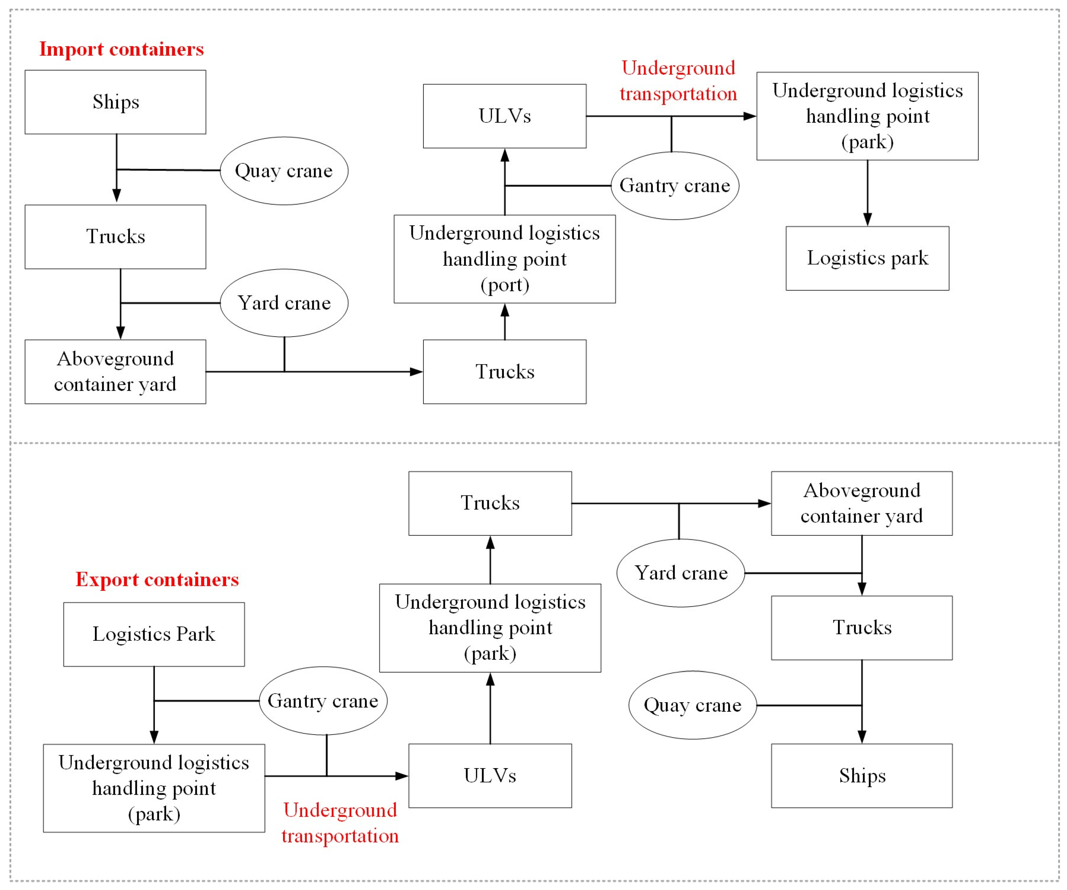
The basic workflows of import and export containers in the underground container logistics system are shown in Figure 2. For import containers, after being unloaded from the ships by quay cranes, some of them are transported by internal trucks directly to the entrance of the shaft, which is the loading/unloading end point of the underground system. The other import containers could be transported to and stored in the above-ground container yard, and each of them will be loaded onto an internal truck by the yard crane and transported to the shaft when called by its destination. There is a gantry crane over the shaft, and it is used to transfer the containers from the internal truck to the ULVs in the deep underground tunnel or vice versa. The trucks may need to wait for the gantry crane since it handles at most one container at a time, and there is a waiting point next to the gantry crane in case of truck congestion. The ULVs will transport the import containers to the destination logistics park through the deep underground tunnel, and the containers will be unloaded from the ULVs by the gantry crane at the shaft in the park. As shown in the lower part of Figure 2, the process is the opposite for the export containers.
Underground logistics transportation has advantages in terms of high transport efficiency, safety, environmental friendliness, short transport cycle, etc., compared to traditional container transportation. According to the above-mentioned workflow, it is necessary to design a reasonable, optimized container yard layout to fit the underground system with a better connection between the underground and the above-ground road transportation and operations. The goal is not only to meet the import and export container storage needs but also to avoid the redundant waiting of related external trucks and the congestion of internal trucks. It is the foundation for facilitating the container yard by applying an underground logistics system to meet the increasing demands.

3.2. Container Yard Layout Design Problem with Underground Logistics System

The container yard is used for stacking and handling containers; its layout design needs to define the container position area, followed by appropriate consideration of the arrival time of different types of containers, the annual throughput of the system, and other affecting features. The underground container logistics system in this paper consists of the following three key parts: (1) Underground logistics handling point. As shown in the left part of (a) in Figure 3, it is the entrance of the shaft, including a gantry crane and different lanes for internal trucks, and is used to complete the interaction between the above-ground operation and underground transportation. (2) Container yard. The yard is used for the temporary storage of containers, and as shown in the right part of (a) in Figure 3, the import and export containers are stored separately. Figure 3b shows an example layout of the container yard with multiple blocks. The containers in this example are placed parallel to the lanes of the handling points. The total area of the yard is fixed, so the number of operating and transportation lanes and the direction of stacking the containers need to be decided to maximize the use of limited land resources. (3) Gates. Since underground transportation connects the port terminal and the logistics park, the gates are necessary between the container yard and the underground logistics handling point, which play the same role as the gates for external trucks to enter the port terminal. The gates ensure that the container information is recorded before being transferred to the underground system.
Based on the above analysis, the goal of our problem is to minimize the handling cost of the system and maximize the estimated throughput of the system. We analyze three features, namely, the direction of stacking the containers in the yard, the configuration of the lanes, and the number of container blocks. The container yard layout design problem is formulated into a mathematical model based on the calculation of total handling and traveling costs in the system, considering different scenarios of the three features. Without loss of generality, we make the following assumptions: (1) Containers are transported in a single-cycle manner by trucks, namely, each truck handles a pickup or a delivery order at each time; (2) Container trucks can only travel in a given direction on each road of the yard; (3) The number of rows is the same for each container block, and so is the number of columns.

4. Theoretical Model Formulation

The goal of the container yard layout design with the underground system is to maximize the estimated system throughput Ω e s t and minimize the total system cost W at the same time, namely max ( Ω e s t W ) . Integer variables M and N are the number of rows and columns of each block in the yard, respectively. Integer variable T is the largest stacking layer in the container area.
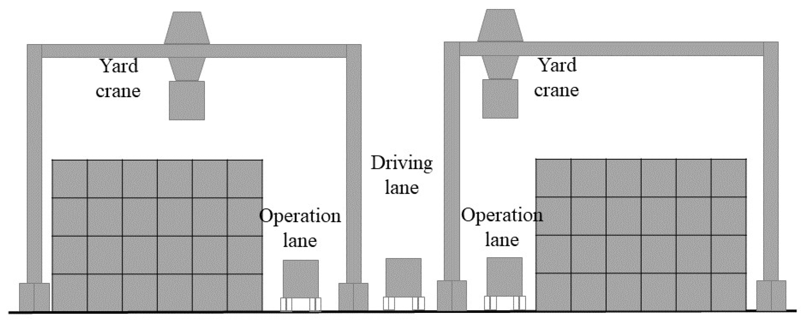
For the container yard, we consider two layouts of lanes, namely a single-lane layout and a dual-lane layout. Figure 4 shows an example of the lanes between two container blocks. There is one unidirectional lane operation lane in each of the blocks and one driving lane between the two blocks. The truck could stop in the operation lanes to let the yard crane load/unload the containers, while the driving lane supports two-way transportation for two trucks at the same time. The single-lane layout indicates that each block has only one operation lane on one side, as shown in Figure 4, and the two adjacent blocks can be seen as a container block group since they share the driving lane. The dual-lane layout means that there is one operation lane on each side of the block, and there are more driving lanes required in this situation.
Define the following integer variables: η = 1 indicates a single-lane layout is chosen, and η = 0 indicates a dual-lane layout. θ = 1 indicates that the direction of stacking the containers is vertical to the lanes at the underground logistics handling point and θ = 0 that the stacking direction is parallel to the handling point. The summary of the notations is in Appendix A.

4.1. Estimated Transportation Distances of Trucks

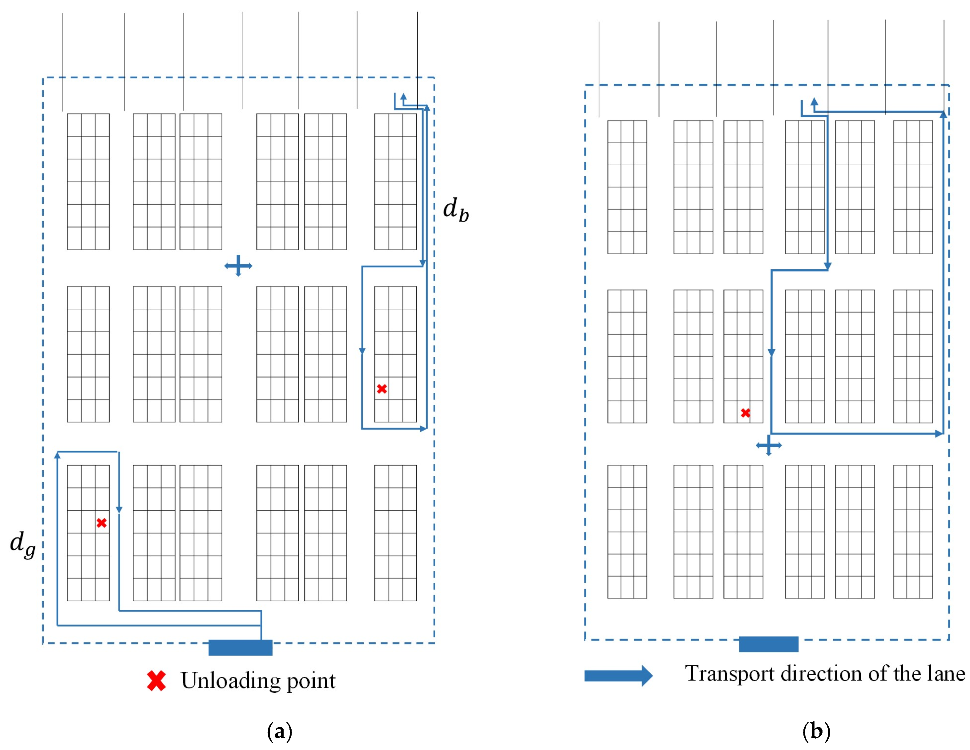
Figure 5 shows the possible transportation routes of the trucks under the single-lane layout and dual-lane layout modes, respectively. Figure 5a shows the single-lane layout, where the vertical direction is the container area operation lane and driving lanes, and the horizontal direction is the transportation lanes. The container truck with an operation instruction drives in the yard in a given direction to arrive at the position of the designated container and then waits for the yard crane operation. In addition, some trucks can directly reach the underground logistics handling point through the two-way driving lane on the left side without entering the yard. Figure 5b is the dual-lane layout mode, there is one driving lane between any two blocks in the yard. According to the driving law of the container truck, the driving path can be divided into horizontal driving distance and vertical driving distance. Also, depending on the source of the truck, the travel path can be divided into the transportation distance from the gate to the yard and the transportation distance from the handling point to the yard.
(1) Transportation distance in single-lane mode.
Scenario 1-a: The direction of container blocks is parallel to the underground logistics handling point.
If the vertical coordinate position of the container truck instruction is located within the range [ ( k 1 ) A M , k A M ], then the container truck’s traveling distance in the vertical direction is 2 k A M . The probability of each line is the same, 1 M . According to the mathematical expectation, the estimated traveling distance in the vertical direction of the container truck is calculated as:
E 1 = 2 A M 2 k = 1 M k = A ( M + 1 M ) .
The horizontal transportation distance on the gate side needs to consider the number of container block group columns. When the number of container group columns is odd ( N = 2), if the range of longitudinal coordinate position of the container truck instruction is located in [ 0 , A M ], the distance traveled by the container truck in the horizontal direction is B , with a probability of 1 M ; if the range of longitudinal coordinate position of the container truck instruction is located in [ A M , A ], the distance traveled by the container truck in the horizontal direction is 2 B , with a probability of M 1 M . When the number of container block group columns is other odd numbers ( N > 2), if the container truck instruction is located in the longitudinal coordinate position range of [ 0 , A M ], the container truck traveling distance in the horizontal direction is B , with the probability of 1 M ; if the container truck instruction is located in the longitudinal coordinate position range of [ A M , A ], the container truck traveling distance in the horizontal direction is either B + [ ( 4 k 2 ) B / N ] or 2 B , with the probability of 4 ( M 1 ) M N or 2 ( M 1 ) M N , and according to the mathematical expectation calculation of the container truck horizontal direction predicted distance of travel is:
E 2 = B 2 M N 2 [ M ( 4 + 3 N 2 ) N 2 4 ] .
When the number of container group columns is even, if the container truck instruction is located in the longitudinal coordinate position range of [ 0 , A M ], the container truck traveling distance in the horizontal direction is B , with the probability of 1 M ; if the container truck instruction is located in the longitudinal coordinate position range of [ A M , A ], the container truck traveling distance in the horizontal direction is B + [ ( 4 k 2 ) B / N ] , with the probability of 4 ( M 1 ) M N , and according to the mathematical expectation calculation of the container truck horizontal direction predicted traveling distance is:
E 2 = B ( 3 M 1 2 M ) .
Based on the above analysis, the estimated travel distance of the container truck from the gate to the yard d g s e is:
d g s e = E 1 + E 2 = B M ( 4 + 3 N 2 ) N 2 4 2 M N 2 + A ( M + 1 M )   ,   i f   N / 2   is   an   odd   number B ( 3 M 1 2 M ) + A ( M + 1 M )   ,   i f   N / 2   is   an   even   number .
The underground logistics handling point side does not set up gates, assuming that the number of transportation channels and the number of columns in the container area are the same. Vertical transportation distance is the same as E 1 , horizontal transportation distance derivation method is similar to E 2 : the probability of each transportation channel selected by the container truck when entering the yard is 1 N , the probability of the driving channel selection to reach the container area where the operation instruction is located is 2 N , so the horizontal estimated driving distance of the container truck is:
d b s e = B 2 ( 2 N + 1 ) 3 N + A ( M + 1 M ) .
Scenario 1-b: The direction of container blocks is vertical to the underground logistics handling point.
When the direction of the container area is vertical to the handling point, the horizontal transportation distance and vertical transportation distance are derived in the same way as above. The estimated transportation distance of the gate-side container card is:
d g s a = B ( N + 1 ) 2 2 N 2 + A ( M 1 M )   ,   i f   N   is   an   odd   number B ( N + 2 2 N ) + A ( M 1 M )   ,   i f   N   is   an   even   number .
The estimated transportation distance of the underground logistics side container truck is:
d b s a = B ( 2 N 2 + 3 N + 1 3 N 2 ) + A ( M 1 M ) .
(2) Transportation distances in dual-lane mode.
Scenario 2-a: The direction of the loading/unloading crossing parallel to the container area.
When the direction of the container area is parallel handling points, the horizontal and vertical predicted transportation distances are derived similarly to E 1 , E 2 . The predicted transportation distance of the container truck on the gate side is:
d g b e = B ( N 3 5 N 2 + 8 N + 4 M N 8 ) M N 2 + A ( M + 1 M ) ,   i f   N   is   an   even   number B [ ( 3 N 3 + 13 N 5 ) ( M 1 ) + 11 N 2 9 M N 2 ] 4 M N 2 + A ( M + 1 M )   ,   i f   N   is   an   odd   number .
The estimated transportation distance for the underground logistics side container truck is:
d b b e = B 2 ( 4 N 2 3 N 1 ) 3 N 2 + A ( M + 1 M )   .
Scenario 2-b: The direction of container blocks is vertical to the underground logistics handling point.
When the container area is oriented vertically to the handling points, the estimated transportation distance of the gate-side container truck is:
d g b a = B ( N + 1 ) 2 2 N 2 + A [ 2 + M ( M 1 ) ] 2 M 2 ,   i f   N   is   an   odd   number B ( N + 2 ) 2 N + A [ 2 + M ( M 1 ) ] 2 M 2 ,   i f   N   is   an   even   number .
The estimated transportation distance for the underground logistics side container truck is:
d b b a = B ( 2 N 2 + 3 N + 1 ) 3 N 2 + A [ 2 + M ( M 1 ) ] 2 M 2 .
Based on the above analysis, the expression for the predicted transportation distance d of the container truck in the yard is:
d = η [ θ ( d g s e + d b s e ) ] + η [ ( 1 θ ) ( d g s a + d b s a ) ] +   ( 1 η ) [ θ ( d g b e + d b b e ) ] + ( 1 η ) [ ( 1 θ ) ( d g b a + d b b a ) ] .

4.2. Estimated Size of Operational Area

In the planning and construction stages of the container yard, it is necessary to estimate the area of its operating area to avoid over-saturation of the yard, leading to congestion in the port area operations, reduced efficiency, and higher operating costs. Referring to the layout planning study of the railroad logistics center, there are two methods to estimate the functional area: the analogical analysis method and the qualitative and quantitative combination of methods. The former has a strong human subjective influence, so this paper adopts the second method to calculate the area of the container yard and the operational length of the underground logistics handling point:
The estimated area of the container yard operation area is:
S = C f ( 1 + λ ) ,
C = ( 1 + μ ) ( 0.75 N 1 t 1 + N 2 t 2 + 0.5 N 3 t 3 ) ,
N 1 = Q 1 γ α 1 365 q , N 2 = Q 2 γ α 2 365 q , N 3 = | N 1 N 2 | ,
where C indicates the average daily container capacity of the yard; f indicates the bottom area of a container; λ indicates the container auxiliary area coefficient; μ indicates the container yard capacity parameter; t 1 ,   t 2 ,   t 3 respectively indicates the detention time of export container, imported container and empty container, the detention time for import and export containers is 1, and the detention time for empty containers is 2; N 1 ,   N 2 ,   N 3 represent the number of containers imported containers, export containers and empty containers, respectively; Q 1 ,   Q 2 indicates that the container yard annual shipments and arrivals; γ indicates that the cargo arrival and departure fluctuation coefficients; α 1 ,   α 2 indicates that the total share of exports and imports of the volume of freight; q is the average net weight of the container.
The estimated operating length of the underground logistics handling point is:
L = Q γ l 365 q c ,
where Q indicates the annual freight arrival and departure volume of underground logistics; l indicates the average length of underground logistics wagon group, and; c is the number of times of daily picking up and delivering wagons of underground logistics.

4.3. Estimated Number of Container Turnovers

In most container yards, the stacking position of containers is randomly arranged by crane personnel and yard planners, with a high degree of disorder. Operations such as import/export container lifting and loading, container retrieval, and transferring to the stacks can result in container-turning operations. This leads to the port’s consumption of excess power and manpower. The number of container turnovers [28] can be calculated by the prediction of the number of shells in the container area and the stacking height, and the stacking height can be calculated by the actual stacking area and the prediction of the container stacking volume. The formula is shown below:
R = ( 2 T 1 ) 4 + ( T + 1 ) 8 α ,
where α denotes the number of columns in each container block.
(1) Estimated stacking heights in single-lane mode.
The number of container zones affects the planning of the number of lanes, thus changing the overall size of the yard area. Calculate the vertical and horizontal lengths of the yard and the height of the container stacks based on the number of lanes, lane widths, and the number of rows and columns of the container zones. For a single-lane layout ( η = 1 ), calculate as follows. e denotes the width of the container area, w denotes the length of the container area, h denotes the width of the horizontal channel between the container areas, and v denotes the width of the vertical channel between the container areas.
A = e M + h M 2 + 2 h B = w N + v ( 1 + N ) .
Actual usable stacking area for containers:
p a = M N w e = e M B e M v ( N 1 ) .
Container stacking height:
T h = S f p a .
The vertical and horizontal lengths of the yard are not only related to the number of rows and columns of the container area but also the constraints of the total area to be considered:
A B S .
(2) Estimated stacking heights in dual-lane mode.
When considering the double-lane layout ( η = 0 ), the actual usable stacking area and stacking height of containers are calculated the same as the single-lane layout, and the vertical length and horizontal length of the yard are calculated as follows:
A = e M + h ( M + 1 ) B = w N + v ( 1 + N ) .

4.4. Estimated Container Throughputs

Throughput represents the operational efficiency of the entire container logistics system, yard storage, container transportation, and crane loading and unloading will produce operating hours. Any delay will have an impact on the operational efficiency of the entire container logistics system, so it is necessary to take into account a comprehensive consideration of the time consumption of all parts of the system, according to the queuing theory and the system network homeostasis [33], to calculate the system’s estimated throughput. t ( D i Q ) denotes the time required for the transportation of a container truck to complete a cycle, N P denotes the number of on-dock container trucks, and N Q denotes the number of gantry cranes at the handling points of the underground logistics.
Ω e s t = i = 1 N Q n = 0 N P λ n Q i π n Q i .
Average system delay time:
λ n Q i = 1 t ( D i Q ) ( N P n ) .
System network homeostasis:
π n Q i = π 0 Q i ( t p t ( D i Q ) ) n N p ! ( N p n ) ! .

4.5. Total System Cost

The cost of the system consists of the cost of container transportation, the handling cost of loading and unloading by cranes, and the yard space occupation cost. The cost of container transportation and handling is divided into two parts for consideration: in in the yard and outside the yard. d represents the estimated transportation distance of the container truck. Based on previous calculations, we have:
W 1 = L c t t t + 0.5 c r t r ,
W 2 = c r t r β R + c t t t β d + ( 1 β ) A c t t t ,
W 3 = A B .
Let a i denote the weight of each component cost, the system cost is calculated as:
W = a 1 W 1 + a 2 W 2 + a 3 W 3 .

5. Algorithm and Experiments

5.1. Improved Tabu Search Algorithm

The tabu search algorithm was proposed by Glover in 1986 [33]. The algorithm mimics the human memory function with memory capacity and amnesty criteria. A tabu table is used to block the region just searched to avoid a circuitous search and jump out of the local optimal solutions. Some good states in the tabu region are amnestied to accept poor solutions during subsequent searches, which in turn ensures the diversity of searches and thus achieves the global optimum.
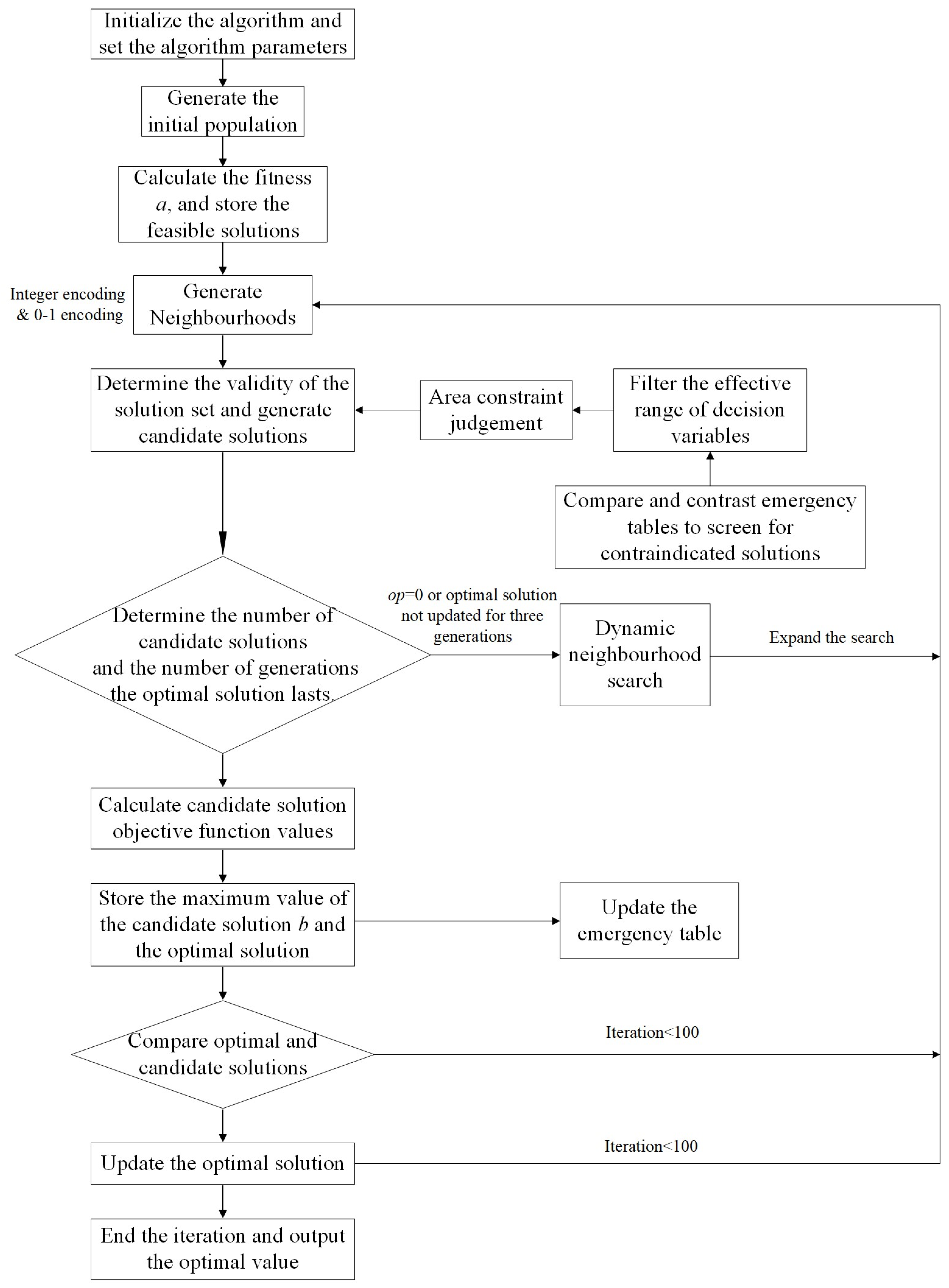
We design an improved tabu search algorithm for the proposed container yard design problem, where a dynamic neighborhood expansion is embedded in the search process. Its coding method is integer coding and a randomized move search for candidate solutions is used. When the optimal solution remains unchanged for three generations or the candidate solutions are all in the tabu table, the search neighborhood is expanded to improve the performance of the algorithm to find the optimal solution. Details of the improved tabu search algorithm are as follows.
(1)
Tabu table: The tabu table records the local optimal point that has been reached. The tabu point will no longer be selected in the next search to prevent the search from looping. The main factors of the tabu table include tabu object, tabu length, and amnesty criterion. The tabu length is the number of times the object in the table stops participating in the search. The amnesty criterion is the appropriate relaxation of the tabu object. When the object in the tabu table meets certain conditions, it can jump out of the tabu table in advance. Too small a step length will reduce the algorithm’s ability to jump out of the local optimal point. We set the tabu length to 200. It increases once for each feasible solution. The tabu is lifted after the tabu step length reaches 200 times. The amnesty criterion sets that when the solution obtained by the object in the tabu table is better than the current neighborhood solution and the tabu step length exceeds 100 times, the tabu can be ended.
(2)
Coding: A candidate solution is defined as an array [ M ,   N ,   T ,   a 1 ,   a 2 ,   a 3 ,   a 4 ] . The variables M ,   N ,   T are integers as those defined in the theoretical model, which defines the size of each container block. a 1 , a 2 , a 3 , a 4 are 0–1 codes regarding the use of single-lane layout, double-lane layout, container block vertical to the underground logistics handling point, and that parallel to the handling point.
(3)
Improved dynamic neighborhood search: The neighborhood size in this algorithm represents the searchability of the tabu algorithm. The larger the neighborhood range, the longer the search time and the greater the probability of reaching the optimal solution. Randomly generate an initial solution x , and define its neighborhood S ( x ) as S ( x ) = x + u d , where u is the random step size, and d is the search direction. The initial search radius r = 2 , that is, the neighborhood size is a 5 × 5 × 5 matrix. When the best solution remains unchanged for three generations or the candidate solutions are all in the tabu table, the search radius is expanded to r equal to r + current generation ⁄ 2 to improve the algorithm’s performance.
(4)
Evaluation function: Select the objective function as the evaluation function, namely Ω e s t W , which indicates to maximize the estimated system throughput and minimize the total system cost.
(5)
Candidate solution selection: According to the generated neighborhood, the feasible solution is checked. If the candidate solution is not in the tabu table, the evaluation value of the candidate solution is calculated, and the candidate solution set is recorded. Otherwise, it is determined whether the amnesty criterion is triggered.
The flow of the improved tabu search algorithm is shown in Figure 6.

5.2. Instance Description and Parameters

In the model, all containers are 20 feet long. The bottom area f of each container is 12 square meters, and the average net weight q of a container is 25 tons. We assume that the detention time of the export container t 1 , imported container t 2 and empty container t 3 are 1, 1, and 2 respectively. The cargo arrival and departure fluctuation coefficients γ is set to 1.2, the total share of exports and imports of the volume of freight α 1 ,   α 2 are all 0.9, the container auxiliary area coefficient λ is 3, and the container yard capacity parameter μ is 0.15. The annual freight arrival and departure volume of underground logistics Q regarding the freight volume of railroads is set as 3.475 million tons. With reference to the railroad container freight, we set Q 1 ,   Q 2 to 10 million tons and 6 million tons. The average length of the underground logistics wagon group l is set to 7 m. The number of times of daily picking up and delivering wagons of underground logistics c is 10. In addition, we consider that the container area specification is 8 shells, the width of the container area is 16.2 m, the length of the container area is 50.88 m, the width of the horizontal channel (bidirectional transportation lane) is 20 m, and the width of the vertical channel (arrival and departure lanes and operation lanes) is 26 m.

5.3. Results and Discussions

We set the largest iteration times as 100 generations. According to the results, the proposed tabu search algorithm reaches a convergence in the 33rd generation. The search neighborhood is expanded from generation 9, and its search radius is expanded from the original 5 × 5 to 51 × 51. The iteration process is shown in Figure 7.
According to the best solution, the container yard with the underground logistics system should consider a single-lane layout, with the containers placed vertically at the underground handling point. The best size of each block is 6 rows and 6 columns, and there are 36 containers in total in each layer. The best vertical length of the yard is 197 m, and the best horizontal length is 487 m. Inside the yard, there are nine transportation lanes, six operation lanes, and three driving lanes between blocks. The overall road network density is 19.8 km per square kilometer. The estimated annual throughput of the system under this layout can reach 10,739,500 Twenty-feet Equivalent Unit (TEU), and the average cost of a single container is 1242.55. The detailed results are shown in the second column of Table 2.
We also compare the best results generated with only one part of the objective by letting one of the weight parameters be 0, namely, to consider only the estimated throughput or only the total cost. As shown in the third column of Table 2, when the objective function only considers the total cost, the overall road network density of the best layout generated is 18.8 km per square kilometer, which is slightly lower than that of the best layout when the comprehensive objective is considered. As shown in the last column of Table 2, when the objective function only considers the throughput, the best solution consists of the dual-lane layout mode with a road density of 30.5 km per square kilometer, and the estimated throughput is 10,860,500 TEU/year. The road density in this case is 54% higher compared to that of the best layout when the comprehensive objective is considered. The increase in road density also leads to an increase in the overall stacking height, which increases the cost of handling the containers.
Based on the experimental results, when introducing underground container logistics systems, port authorities need to consider their conditions and main goals to optimize the design of container yards. This study comprehensively considers the total throughput and operating cost goals and obtains a satisfactory yard layout design through an improved taboo search algorithm. In practice, if the main goal is to reduce the total operation and transportation costs, the design direction of the container yard with the underground logistics system is to expand the container block area and reduce the road density with a single-lane layout. When the main goal is to increase the total throughput, the design direction of the container yard with the underground logistics system is a dual-lane mode to increase road density and improve operational efficiency.
Considering that land is the most critical and relatively scarce resource in the container yard design problem, we conducted a sensitivity analysis of the yard space occupation cost coefficient, a 3 . The results are shown in Table 3. The results of the analyses show that the total estimated throughput decreases slightly with the increase in the cost coefficient, but the overall change is not significant. Vertical layout was preferred in all cases. As the cost coefficient increases, the resulting design solutions show a decreasing trend in road density, and the layout of the yard changes from a dual-lane to a single-lane layout.

6. Conclusions

This paper proposes a container yard design problem considering an underground logistics system. The structure and workflow of the underground container logistics system are analyzed, and key features are recognized for the yard design problem, such as the container block layout direction, the lane configuration in the yard, and the number of container blocks. We formulate the problem into theoretical models under different scenarios of the key features with the comprehensive objective of maximizing the total throughput and minimizing the total operation cost simultaneously. An improved tabu search algorithm is designed to solve the problem.
Experimental results show that the proposed algorithm can generate a satisfactory layout design solution for the real-size instance, where the single-lane layout and the vertically placed block are applied. By comparing the results of a single objective of throughput maximization, total cost minimization, and their combination, the single-lane layout model is superior to the dual-lane layout model in terms of operation and transportation costs, while the dual-lane layout model could result in higher estimated throughput. The best layout derived from the comprehensive objective can meet the requirement for efficient operation of the underground container logistics system and control the total operation cost at the same time. Our research studies different container yard design options for introducing the underground logistics system into port terminals, which provides an important scientific foundation for promoting the application of underground container logistics systems.
Future studies could consider more comprehensive features of the underground container logistics system. For example, different transportation rules for trucks and ULVs, such as priorities or grouping. One can also consider a mix of the single-lane and dual-lane layout modes.

Author Contributions

Conceptualization, B.L., M.Z. and C.L.; methodology, Y.W.; software, B.L.; validation, C.L., Y.W., M.Z. and H.L.; formal analysis, H.L. and M.Z.; investigation, B.L. and M.Z.; resources, H.L. and X.X.; data curation, H.L. and X.X.; writing—original draft preparation, C.L.; writing—review and editing, X.X. and M.Z.; visualization, B.L.; supervision, H.L.; project administration, Y.W. and B.L.; funding acquisition, Y.W. and B.L. All authors have read and agreed to the published version of the manuscript.

Funding

This research was funded by the Shanghai Rising-Star Program (21QB1404800), and Shanghai Sailing Program (21YF1416400).

Institutional Review Board Statement

Not applicable.

Informed Consent Statement

Not applicable.

Data Availability Statement

The original contributions presented in the study are included in the article, further inquiries can be directed to the corresponding author.

Conflicts of Interest

The authors declare no conflicts of interest.

Appendix A

Table A1. Notations.
SymbolDescription
A , B The vertical and horizontal lengths of the container yard, respectively (meter).
C The average number of containers stacked (TEU).
C d The average daily container capacity of the container operation area (TEU/day).
E 1 ,   E 2 The estimated transportation distance of the container truck in the vertical and horizontal directions, respectively (meter).
L The effective length of underground logistics loading and unloading lines (meter).
M ,   N The number of rows and columns of the container area, respectively.
N 1 ,   N 2 ,   N 3 The number of containers issued, arriving, and empty containers, respectively.
N P The number of on-dock container trucks.
N Q The number of gantry cranes at the handling points of the underground logistics.
Q w The annual cargo arrival and departure volume of underground logistics (ton).
Q 1 ,   Q 2 The annual shipment and arrival of cargoes in the container operation area, respectively (ton).
R The number of container area berths.
S The container operation area (square meter).
T The number of stacking layers in the container area.
T h The container stacking height (meter).
W The total system cost (RMB).
W 1 ,   W 2 ,   W 3 The container transportation costs, handling costs and yard space occupation costs, respectively (RMB).
Ω e s t The estimated system throughput (TEU/year).
η The lane pattern of the yard.
θ The loading and unloading crossings for lanes.
γ The freight arrival and departure fluctuation factor.
λ The container auxiliary area coefficient.
λ n Q i The average system delay time (second) .
μ The container yard capacity parameters.
π n Q i The system network homeostasis.
a 1 ,   a 2 ,   a 3 The weight s of the container transportation costs, handling costs and yard space occupation costs, respectively.
c The daily pickup and delivery times of underground logistics.
c r The spreader cost per second (RMB).
c t The cost per second (RMB).
d The expression for the predicted transportation distance of the container truck in the yard (meter).
d b b a The estimated transportation distance for underground logistics side container truck (meter).
d b s a The estimated transportation distance of the underground logistics side container truck (meter).
d b s e The horizontal estimated driving distance of the container truck (meter).
d g b a The estimated transportation distance of the gate side container truck (meter).
d g b e The predicted transportation distance of the container truck on the gate side (meter).
d g s a The estimated transportation distance of the gate side container truck (meter).
d g s e The predicted travel distance of the container truck from the gate to the yard (meter).
d w The off-site handling distance (meter).
e The width of container area (meter).
f The bottom area of a single container (square meter).
h The horizontal aisle width (meter).
l The average Length of Underground Logistics Fleet (meter).
p a The actual usable stacking area for containers.
q The average net container weight (ton).
q w The average net weight of transportation trucks (ton).
t ( D i Q ) The time required for the transportation of a container truck to complete a cycle (second).
t r The spreader handling time per trip (second).
t t The truck travel time per meter (second).
t 1 ,   t 2 ,   t 3 The detention time of the export container, imported container and empty container, respectively (second).
v The vertical aisle width (meter).
w The length of container area (meter).

References

  1. Liu, W.; Yang, Y.; Luo, Q.; Zeng, X.; Chen, C.; Zhu, J.; Lin, W.; Chen, H.; Huo, W.; He, M.; et al. Study on the Contribution of Seaport to Urban Economy: An Empirical and Quantitative Analysis of Xiamen Port. J. Mar. Sci. Eng. 2022, 10, 1753. [Google Scholar] [CrossRef]
  2. Li, H.; Jiang, L.; Liu, J.; Su, D. Research on the Evaluation of Logistics Efficiency in Chinese Coastal Ports Based on the Four-Stage DEA Model. J. Mar. Sci. Eng. 2022, 10, 1147. [Google Scholar] [CrossRef]
  3. Liu, A.; Wei, Y.; Yu, B.; Song, W. Estimation of Cargo Handling Capacity of Coastal Ports in China Based on Panel Model and DMSP-OLS Nighttime Light Data. Remote Sens. 2019, 11, 582. [Google Scholar] [CrossRef]
  4. Ducruet, C.; Cuyala, S.; El Hosni, A. Maritime networks as systems of cities: The long-term interdependencies between global shipping flows and urban development (1890–2010). J. Transp. Geogr. 2018, 66, 340–355. [Google Scholar] [CrossRef]
  5. Rodrigue, J.P. The Geography of Transport Systems; Routledge: London, UK, 2020. [Google Scholar]
  6. Chen, J.; Fei, Y.; Zhu, Y.; Zhang, F. Allometric relationship between port throughput growth and urban population: A case study of Shanghai port and Shanghai city. Adv. Mech. Eng. 2018, 10, 1687814018760933. [Google Scholar] [CrossRef]
  7. Ren, M.; Fan, Z.; Wu, J.; Zhou, L.; Du, Z. Design and optimization of underground logistics transportation networks. IEEE Access 2019, 7, 83384–83395. [Google Scholar] [CrossRef]
  8. Guo, D.; Chen, Y.; Yang, J.; Tan, Y.; Zhang, C.; Chen, Z. Planning and application of underground logistics systems in new cities and districts in China. Tunn. Undergr. Space Technol. 2021, 113, 103947. [Google Scholar] [CrossRef]
  9. Hai, D.; Xu, J.; Duan, Z.; Chen, C. Effects of underground logistics system on urban freight traffic: A case study in Shanghai, China. J. Clean. Prod. 2020, 260, 121019. [Google Scholar] [CrossRef]
  10. Chen, Y.; Guo, D.; Chen, Z.; Fan, Y.; Li, X. Using a multi-objective programming model to validate feasibility of an underground freight transportation system for the Yangshan port in Shanghai. Tunn. Undergr. Space Technol. 2018, 81, 463–471. [Google Scholar] [CrossRef]
  11. Liang, C.; Hu, X.; Shi, L.; Fu, H.; Xu, D. Joint dispatch of shipment equipment considering underground container logistics. Comput. Ind. Eng. 2022, 165, 107874. [Google Scholar] [CrossRef]
  12. Hu, W.; Dong, J.; Xu, N. Multi-period planning of integrated underground logistics system network for automated construction-demolition-municipal waste collection and parcel delivery: A case study. J. Clean. Prod. 2022, 330, 129760. [Google Scholar] [CrossRef]
  13. Abbas, F. Intelligent Container Stacking System at Seaport Container Terminal. Master’s Thesis, Blekinge Institute of Technology, Karlskrona, Sweden, 2016. [Google Scholar]
  14. Aulin, V.; Hrynkiv, A.; Lyashuk, O.; Vovk, Y.; Lysenko, S.; Holub, D.; Zamota, T.; Pankov, A.; Sokol, M.; Ratynskyi, V.; et al. Increasing the Functioning Efficiency of the Working Warehouse of the “UVK Ukraine” Company Transport and Logistics Center. Commun.-Sci. Lett. Univ. Zilina 2020, 22, 3–14. [Google Scholar] [CrossRef]
  15. Pielage, B.; Rijsenbrij, J. Developments in underground freight transportation. In The Future of Automated Freight Transport: Concepts, Design and Implementation; Edward Elgar Publishing: Cheltenham, UK, 2005; pp. 65–84. [Google Scholar]
  16. Böhm, M.; Del Rey, A.F.; Pagenkopf, J.; Varela, M.; Ploster, S.; Calderón, B. Review and comparison of worldwide hydrogen activities in the rail sector with special focus on on-board storage and refueling technologies. Int. J. Hydrogen Energy 2022, 47, 38003–38017. [Google Scholar] [CrossRef]
  17. Visser JG, S.N. The development of underground freight transport: An overview. Tunn. Undergr. Space Technol. 2018, 80, 123–127. [Google Scholar] [CrossRef]
  18. Gong, D.; Tian, J.; Hu, W.; Dong, J.; Chen, Y.; Ren, R.; Chen, Z. Sustainable Design and Operations Management of Metro-Based Underground Logistics Systems: A Thematic Literature Review. Buildings 2023, 13, 1888. [Google Scholar] [CrossRef]
  19. Vernimmen, B.; Dullaert, W.; Geens, E.; Notteboom T’Jollyn, B.; Gilsen, W.; Winkelmans, W. Underground logistics systems: A way to cope with growing internal container traffic in the port of Antwerp? Transp. Plan. Technol. 2007, 30, 391–416. [Google Scholar] [CrossRef]
  20. Fan, Y.; Liang, C.; Hu, X.; Li, Y. Planning connections between underground logistics system and container ports. Comput. Ind. Eng. 2020, 139, 106199. [Google Scholar] [CrossRef]
  21. Rezaeifar, F.; Najafi, M.; Kaushal, V.; Huff, B. Development of a Model to Optimize the Operations of an Intermodal Underground Logistics Transportation. J. Pipeline Syst. Eng. Pract. 2022, 13, 04022039. [Google Scholar] [CrossRef]
  22. Pan, Y.; Liang, C.; Dong, L. A two-stage model for an urban underground container transportation plan prob-lem. Comput. Ind. Eng. 2019, 138, 106113. [Google Scholar] [CrossRef]
  23. Gao, Y.; Chang, D.; Yuan, J.; Liang, C. Scheduling of yard truck considering loading and unloading simultaneously in an under-ground container logistics system. Transp. Res. Rec. 2023, 2677, 246–263. [Google Scholar] [CrossRef]
  24. Kim, K.H.; Park, Y.M.; Jin, M.J. An optimal layout of container yards. Or Spectr. 2008, 30, 675–695. [Google Scholar] [CrossRef]
  25. Abu Aisha, T.; Ouhimmou, M.; Paquet, M. Optimization of container terminal layouts in the seaport—Case of port of Montre-al. Sustainability 2020, 12, 1165. [Google Scholar] [CrossRef]
  26. Taner, M.E.; Kulak, O.; Koyuncuoğlu, M.U. Layout analysis affecting strategic decisions in artificial container terminals. Comput. Ind. Eng. 2014, 75, 1–12. [Google Scholar] [CrossRef]
  27. Wiese, J.; Suhl, L.; Kliewer, N. Mathematical models and solution methods for optimal container terminal yard layouts. Or Spectr. 2010, 32, 427–452. [Google Scholar] [CrossRef]
  28. Petering, M.E.H. Effect of block width and storage yard layout on marine container terminal performance. Transp. Res. Part E Logist. Transp. Rev. 2009, 45, 591–610. [Google Scholar] [CrossRef]
  29. Woo, Y.J.; Kim, K.H. Estimating the space requirement for outbound container inventories in port container terminals. Int. J. Prod. Econ. 2011, 133, 293–301. [Google Scholar] [CrossRef]
  30. Lee, B.K.; Lee, L.H.; Chew, E.P. Analysis on container port capacity: A Markovian modeling approach. OR Spectr. 2014, 36, 425–454. [Google Scholar] [CrossRef]
  31. Stojaković, M.; Twrdy, E. Efficiency Evaluation of a Small Container Terminal with Perpendicular Yard Layout Using Shuttle Carriers. J. Mar. Sci. Eng. 2023, 11, 449. [Google Scholar] [CrossRef]
  32. Lee, B.K.; Kim, K.H. Optimizing the yard layout in container terminals. OR Spectr. 2013, 35, 363–398. [Google Scholar] [CrossRef]
  33. Glover, F. Future paths for integer programming and links to artificial intelligence. Comput. Oper. Res. 1986, 13, 533–549. [Google Scholar] [CrossRef]
Figure 1. Schematic diagram of the underground container logistics system.
Jmse 12 01103 g001
Figure 2. Workflow of underground container logistics system.
Jmse 12 01103 g002
Figure 3. Schematic diagram of the container yard layout with underground system. (a) Top view of container yard layout with underground system. (b) Example layout of the container yard with multiple blocks.
Jmse 12 01103 g003
Figure 4. Front view of two container blocks in a yard.
Jmse 12 01103 g004
Figure 5. Container truck transportation routes in single-lane and dual-lane modes. (a) Container truck transportation routes in single-lane layout; (b) Container truck transportation routes in dual-lane layout.
Jmse 12 01103 g005
Figure 6. Improved Tabu Search Algorithm.
Jmse 12 01103 g006
Figure 7. Algorithm iteration diagram.
Jmse 12 01103 g007
Table 1. Summary of Existing Studies.
Title 1 Research ContentReference
System design of underground container logistics systems[19] Vernimmen et al. (2007), [20] Fan et al. (2020)
System operations of underground container logistics systems[10] Chen et al.(2018), [22] Pan et al. (2019)
[21] Rezaeifar et al.(2022), [11] Liang et al. (2019)
[23] Gao et al. (2023)
Container block planning[24] Kim et al. (2008), [28] Petering et al. (2009)
[27] Wiese et al. (2010), [26] Taner et al. (2014)
[25] Abu Aisha et al. (2020)
Resource allocation of container yard[29] Woo et al. (2011), [32] Lee et al. (2013)
[30] Lee et al. (2014), [31] Stojaković et al. (2023)
Table 2. Best yard design results of different objective weights.
Yard DesignConsider Throughput
and Operating Costs
Consider Only
Total Costs
Consider Only Throughput
Number of columns683
Number of rows649
Layout directionVertical to the loading portVertical to the loading portParallel to the loading port
Lane configurationSingle-lane layoutSingle-lane layoutDual-lane layout
Effective length of
loading/unloading line
(meter)
205205205
Vertical length of yard
(meter)
197 249128
Horizontal length of yard
(meter)
487 333641
Single operation cost
(RMB/task)
1242.551228.801878.50
Estimated system throughput
(10,000 TEU/year)
1073.951072.081086.05
Overall road network density
(km/sq.km)
19.818.830.5
Table 3. Sensitivity analyses of yard space occupation cost coefficient.
Cost Coefficients0.20.40.60.8
Number of columns106106
Number of rows3634
Maximum Stacking Height4345
Layout directionVertical to the loading portVertical to the loading portVertical to the loading portVertical to the loading port
Lane configurationDual-lane layoutSingle-lane layoutSingle-lane layoutSingle-lane layout
Footprint of the yard
(Square meter)
97,79295,93977,31265,601
Operating cost
(RMB/task)
122.96124.26123.67122.89
Estimated system throughput
(10,000 TEU/year)
1073.91073.751072.81071.3
Disclaimer/Publisher’s Note: The statements, opinions and data contained in all publications are solely those of the individual author(s) and contributor(s) and not of MDPI and/or the editor(s). MDPI and/or the editor(s) disclaim responsibility for any injury to people or property resulting from any ideas, methods, instructions or products referred to in the content.