Article

Optimization Design of Radial Clearance between Stator and Rotor of Full Cross-Flow Pump Units

College of Hydraulic Science and Engineering, Yangzhou University, Yangzhou 225009, China
*
Author to whom correspondence should be addressed.
J. Mar. Sci. Eng. 2024, 12(7), 1124; https://doi.org/10.3390/jmse12071124
Submission received: 8 June 2024 / Revised: 27 June 2024 / Accepted: 2 July 2024 / Published: 4 July 2024
(This article belongs to the Section Ocean Engineering)

Abstract

:
Influenced by the clearance flow between stator and rotor, the operational performance and hydraulic performance of full cross-flow pump units are often worse than that of semi-cross-flow pumps. In order to explore the influence mechanism of clearance structural parameters on clearance flow and provide a reliable scientific support for the improvement of both external and internal characteristics of full cross-flow pump units, firstly, the optimization of the stator–rotor clearance structure was studied as research entry point and the radial inlet and outlet clearance width were taken to set up design variables. Secondly, to establish a comprehensive optimization objective function considering both the operational performance and the hydraulic performance of the pump, the information weight method was adopted by weighting four evaluation indexes, namely, head coefficient, efficiency coefficient, vortex average radial deflection coefficient and axial velocity uniformity coefficient, which were calculated by numerical simulation. Finally, the relevant optimization design analysis was carried out by establishing the response surface model, with the optimal objective value obtained by conducting the steepest-descent method. The results show that the response of the radial inlet and outlet clearance width coefficient between stator and rotor to the comprehensive objective function is not directly coupled and the influence of the radial inlet clearance width coefficient on the objective function is higher than that of the radial outlet clearance width coefficient. The parameter optimization outcomes are as follows: the width coefficient of radial inlet clearance between stator and rotor is 2.2 and that of radial outlet clearance is 3.6, in which case the disturbance effect of clearance flow on the mainstream flow pattern in the pump can be significantly reduced, with the export cyclic quantity of the guide vane obviously decreased and the outlet flow pattern of the pump unit greatly improved. Verified by the model test, the average lift of the pump unit was increased by about 7.6% and the maximum promotion of the unit efficiency reached 5.2%.

1. Introduction

A pump is a kind of machinery that can deliver liquid, mainly driven by a motor during which the mechanical energy is converted into the potential energy and kinetic energy of pumping liquid, so that the liquid can be carried from a lower to a higher point [1]. In coastal areas, a pump is a commonly applied mechanical device to eliminate waterlogging [2], and a full cross-flow pump is a new type of axial-flow pump with its impeller directly installed in the inner cavity of the motor rotor [3]. Due to the integration of pump and motor, the axial size of the whole pump unit installation section is greatly shortened [4] and the tip clearance between the impeller and the blade is non-existent [5]. However, during the actual operation of the full cross-flow pump unit, due to the existence of clearance flow between stator and rotor [6], the flow pattern in the mainstream area of the impeller chamber is inevitably disturbed, which can eventually lower the operational performance of the pump unit, along with affecting its safety [7].
With the full cross-flow pump, most people’s cognition still stays at the phase of low operating efficiency and its recognition is still relatively low, compared with the semi-cross-flow pump unit. However, in recent years, with the continuous development of material science and industrial manufacturing levels, the manufacturing materials and processing technology of the motor’s stator and the rotor of the full cross-flow pump have been greatly improved [8] and some scholars have begun to study the performance improvement of the full cross-flow pump unit. Shi et al. [9] found that the lower performance of full cross-flow pumps relative to that of the standard axial-flow pump is due to the existence of clearance reflux by analyzing the fluid–structure interaction. Meng et al. [10] held that the total energy dissipation rate near the suction side of the impeller will gradually increase with the increase of the clearance radius due to the influence of reflux clearance. Shi et al. [11] found that under the condition of low flow, the pressure fluctuation at the entrance of the impeller of the full cross-flow pump noticeably changed and the amplitude of the main frequency declined with the increase of flow velocity. Xu et al. [12] proposed a full-current pump motor optimization scheme from the perspective of motor structure and pump vane structure by carrying out the Maxwell electromagnetic field calculation, CFD simulation and GA–BP neural network algorithm, summarizing a full-current pump motor efficiency calculation method based on the loss separation method. At present, most studies have shown that the clearance reflux can greatly affect the operational performance of full cross-flow pump units, but the influence mechanism of clearance structural parameters on clearance flow is still indistinct and optimization work on its hydraulic characteristics is scarce. If the hydraulic characteristics of the clearance flow between stator and rotor can be improved with a reliable scientific support, the key deficiency of the low operating efficiency of full cross-flow pumps can be optimized, and this type of pump can be better developed and applied [13].
The response surface model is a kind of analytical model which can fit various orders between target variables and design variables [14]. Through experiment, the polynomial function relationship between response variable and design variable can be obtained [15] and the unknown and complex function relationship between them can be described as an approximation of the real function [16], in which case the optimization efficiency can be improved by analyzing the model [17]. Peng et al. [18] applied this to the optimization of design-size parameters of multiphase pumps, optimizing the combination of inlet angle, outlet angle and blade-wrapping angle of the impeller which significantly improved the performance of the optimized pump under high GVF. Abdellah et al. [19] applied the response surface method to optimize the design parameter combination of the new gear pump and by taking the pump unit efficiency as the objective function, the combination of pump inlet diameter and impeller speed parameters at the optimal design operating point was obtained. Velasquez et al. [20] used the response surface methodology to optimize the geometric parameter combination of the turbine, including the ratios between the basin diameter and the outlet diameter, the basin height, the inlet channel width, the inlet channel height, the inlet channel length and the wrap-around angle, so that the turbine can operate under the highest circulation. Therefore, it can be considered that the response surface optimization design method can be applied to the optimization analysis of pump structural parameters, which can give a functional relationship between design variables and target values, find out the optimal design and reduce the workload of numerical calculation, thus improving the efficiency of calculation.
Aiming at exploring the influence mechanism of clearance structural parameters on clearance flow, and providing scientific support for the multi-objective optimization of the radial clearance between stator and rotor of full-flow pumps, this paper intends to consider the coupling effects of inlet clearance width and outlet clearance width, proposing a response surface model combining the information weight method and numerical simulation. By establishing a polynomial function relationship between the design parameters of the radial stator–rotor clearance and comprehensive objective function representing both the unit performance and flow field hydraulic characteristics—the influence weight of factors on the comprehensive objective function were analyzed. After regression fit-ting, the design parameters of the radial inlet and outlet clearance width between stator and rotor were optimized, and the performance test and flow field analysis of the predicted optimal scheme were carried out in combination with model tests and numerical simulations, respectively, realizing the improvement of both hydraulic and operational performance of the full cross-flow pump unit.

2. Research Methods

2.1. Numerical Simulation

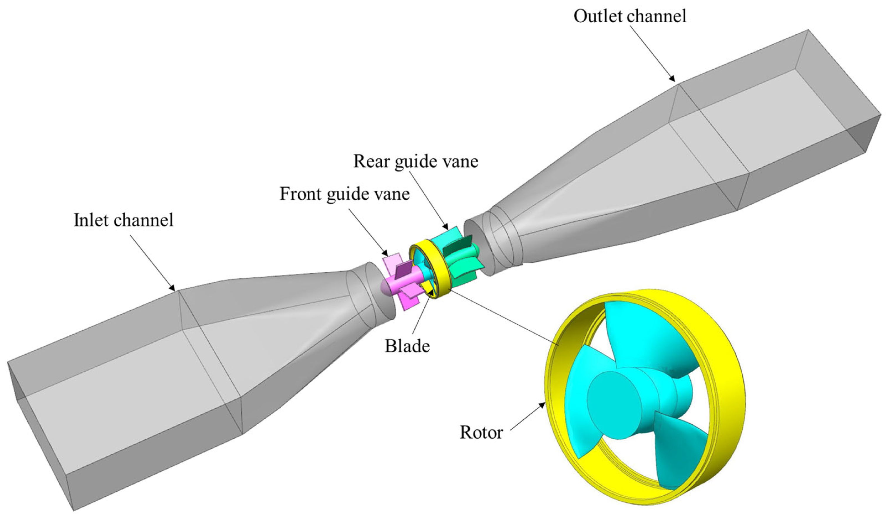
2.1.1. Calculation Area

Based on FLUENT 19.2 numerical simulation software, a three-dimensional numerical simulation model of a full cross-flow pump was established and its calculation area is shown in Figure 1. The number of model blades and guide vanes were 3 and 5, respectively, the size of the hub was 107.3 mm, the placement angle of the blade was +2°, the diameter of the impeller was 0.3 m and the test speed was 1087.5 r/min. Limited by the structure of the full cross-flow pump, the intermediate clearance width between stator and rotor was set to r.

2.1.2. Turbulence Model

The internal flow of the water pump unit was recognized as an incompressible three-phase flow [21,22]. In this study, the Reynolds number reached 1.96 × 10⁶, indicating that the turbulence was complex and the RNG k-ε model was adopted to simulate the flow pattern in the pump unit, which has a high calculation accuracy [23] derived from the transient momentum conservation equation employed by previous scholars using the renormalization group method, which is suitable for dealing with turbulent motion with high strain rate and related problems with swirling flow [24].
The RNG k-ε model can be expressed as follows:
ρ k t + ρ k u i x i = x j α k μ e f f k x j + G k + ρ ε
ρ ε t + ρ ε u i x i = x j α ε μ e f f ε x j + C 1 ε k G k + C 2 ε ρ ε 2 k
C 1 ε = C 1 ε η 1 η / η 0 1 + β η 3
where x i and x j represent directional axes; u i and u j are velocity vectors in x i and x j directions, respectively; k is turbulent kinetic energy; ε is turbulent energy dissipation rate; g is gravitational acceleration; ρ is fluid density; and μ e f f is turbulent effective viscosity coefficient.

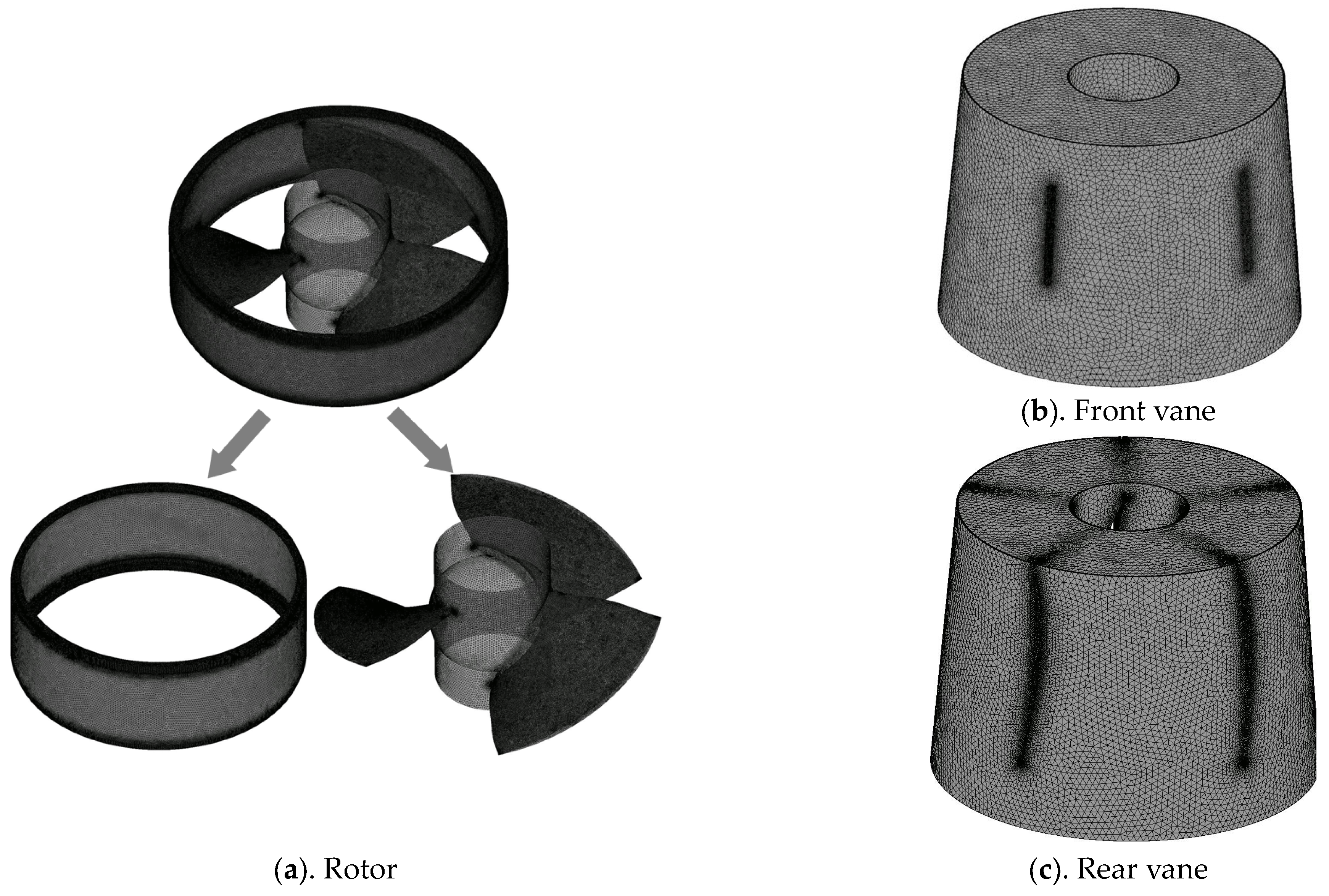
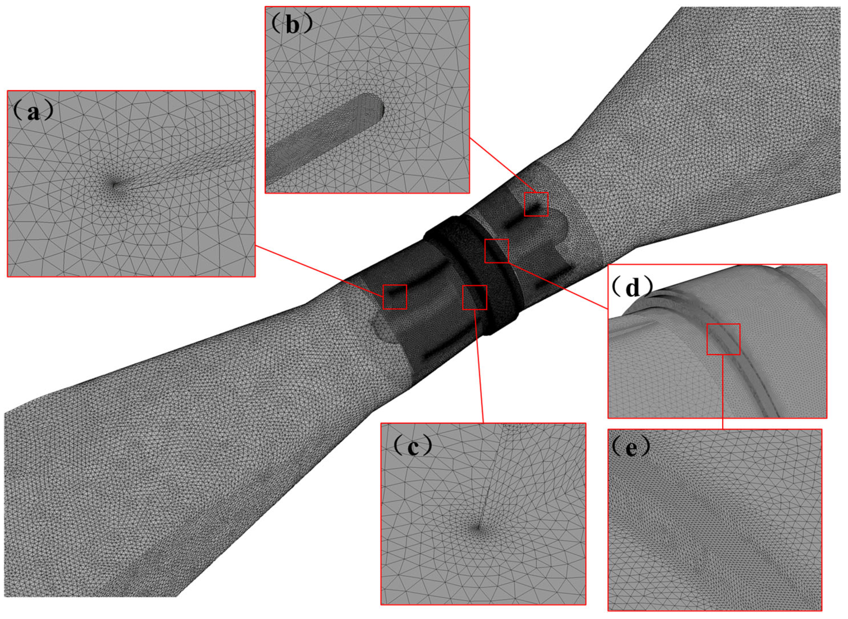
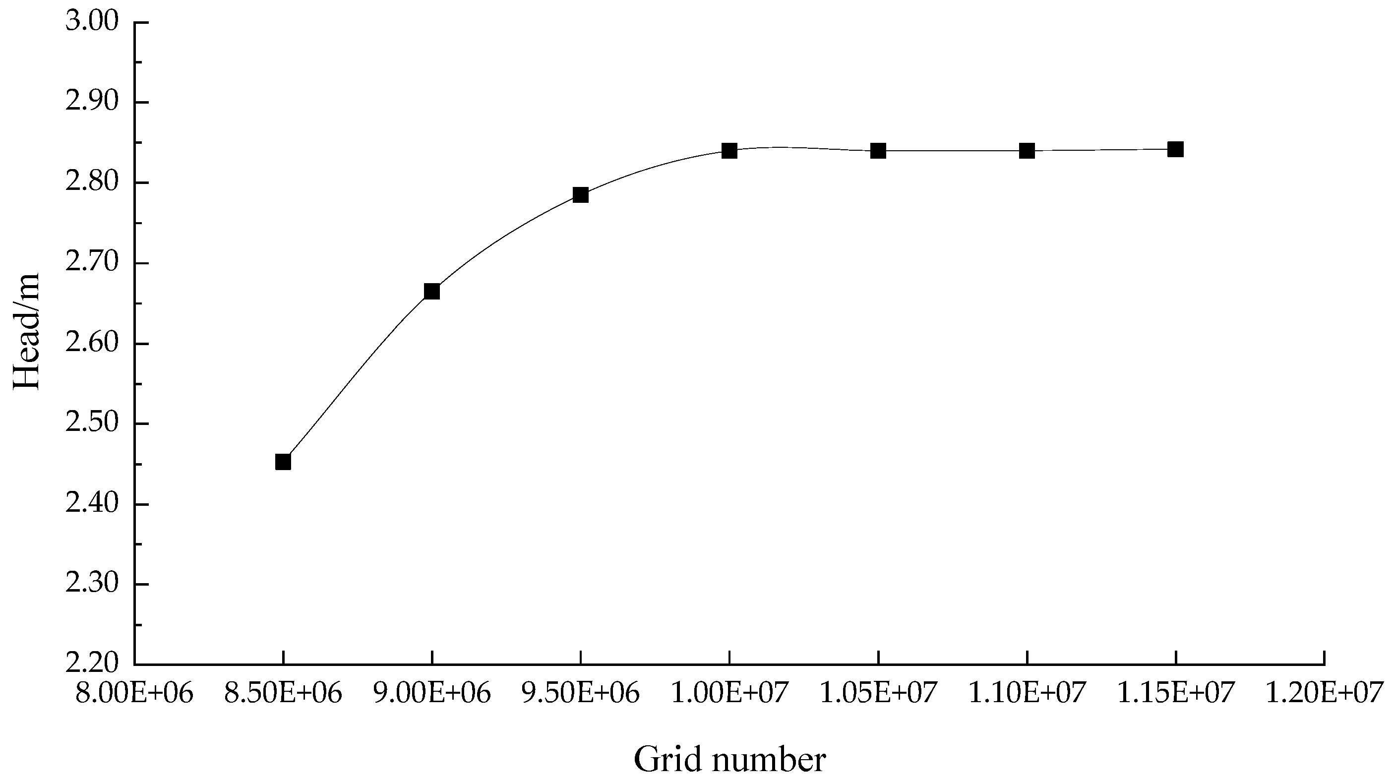
2.1.3. Grid Division

The accuracy and quality of the grid have a great influence on the calculation results [25]. The main research object of this paper was the rotor of the full cross-flow pump, including the impeller and its outer ring, and the unstructured grid was adopted in ANSYS Mesh, with the outer ring of the pump unit directly connected with the impeller chamber section. To be specific, the grid was tetrahedral unstructured and the grid number of the rotor was about 8.3 million, with its orthogonal quality coefficient larger than 0.3. The grids of the main parts of pump unit are shown in Figure 2, of which both the orthogonal quality coefficients of front vane and rear vane were larger than 0.6.
With the mesh near the wall encrypted, parameter y+ was introduced to measure whether the value of the boundary layer of wall was reasonable. The local details of the mesh are shown in Figure 3, where the average y+ values at blade, hub and rim were 67.3, 34.5 and 82.3, respectively, meeting the requirements of the turbulence model for calculation accuracy [26].
In order to meet the requirement of calculation accuracy [27], the grid of the calculation model was analyzed as a typical case and the result of the analysis is shown in Figure 4. It can be found that when the total number of grids was less than 10 million, the head performance of the pump unit gradually increased with the expansion of the grid number, while when the total number of grids was greater than 11 million, the head performance of the pump unit tended to be stable and the relative error was less than 1%, in which case the grid number of the rotor was 8.3 million.

2.1.4. Boundary Condition

In this study, two types of regions were included in the numerical simulation of the pump unit, of which one was the rotation domain mainly in the impeller chamber, and the other was the static domain. A dynamic and static interface was set between the impeller chamber and the leading blade section, and the outer ring section and the rear guide blade segment. In this study, the “Stage-average Velocity” interface was used to transfer the flow parameters between the two surfaces and the matching value was set to 1, while the rest of the static–static interface was set to “None”. Additionally, the inlet boundary condition was set as pressure inlet with a standard atmosphere, the outlet boundary condition was set as constant mass flow and the wall boundary was set as smooth wall without slip.

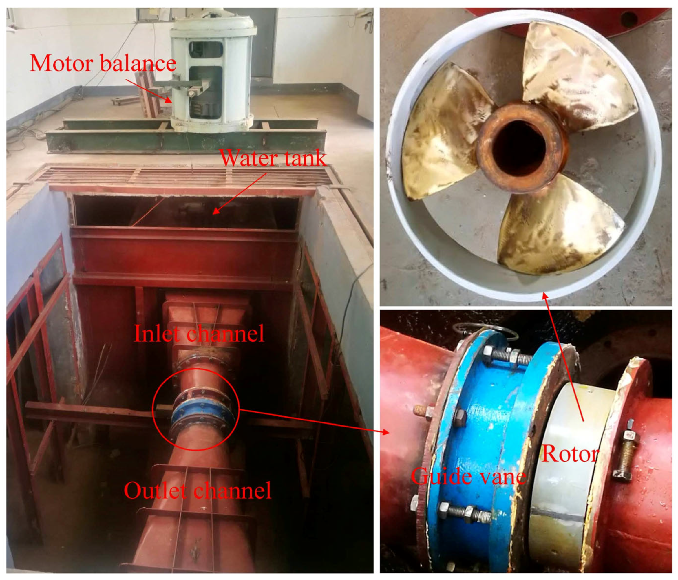
2.2. Physical Model Test

Through the previous multi-scheme comparison and research, a TJ04-ZL-07 model was selected as the test pump model and the type of full cross-flow pump was adopted for installation; that is, the motor and the pump were integrated and the rated speed of the motor was 1087.5 r/min. In addition, the number of blades of the water pump model was set as 3, the diameter of the impeller was set as 300 mm, the diameter of the hub was set as 107.3 mm and the blade angle was fixed at +2°. To form a model pump unit, the size of the water pump model was matched with the inlet and outlet channel, determined according to the same model ratio. The “Hydraulic Machine Test Method” was adopted in the model test and in order to facilitate the water supply the long shaft extended from the inlet end of the pump unit into the shaft in the inlet water tank. Mechanical seals and roller bearings were arranged where the long shaft passed through the shaft and a special gearbox shaped like an umbrella was installed in the shaft to realize the transmission between the vertical power engine and the model pump. The photo of the model pump unit is shown in Figure 5.

2.3. Multi-Objective Optimization Based on Information Weight Method

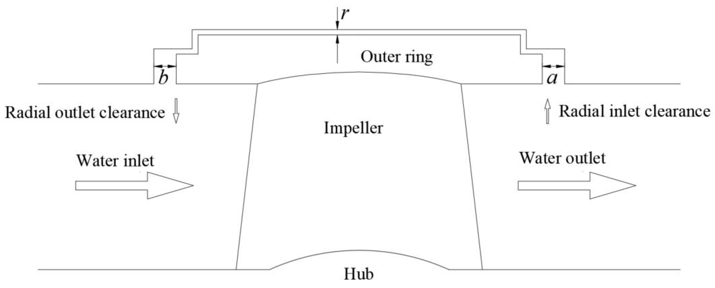
2.3.1. Selection of Research Parameters

For the full cross-flow pump unit, on the one hand, the clearance flow between the stator and rotor can cool the motor; on the other hand, it inevitably disturbs the flow field in the impeller chamber. For its cooling effect, the larger the clearance flow, the better, while regarding the hydraulic performance of the pump unit, the smaller the clearance flow, the better. Further, according to the research results of reference [28], the value of the stator–rotor clearance flow is mainly determined by the minimum clearance width on its path, so when the radial clearance width of the stator and rotor is greater than the intermediate clearance width, the change of the radial clearance width will not have an obvious effect on the clearance flow value. Based on such theories, when the interstitial flow is constant, the inflow and outflow velocity of the corresponding interstitial flow can be reduced by properly increasing the inflow and outflow area of the interstitial flow. Furthermore, to a certain extent, it can reduce the occurrence of the entrainment phenomenon and the disturbance of interstitial flow to the mainstream. Therefore, as shown in Figure 6, this paper selected the radial clearance parameters between stator and rotor as the representative research factors, including the inlet clearance width a and the outlet clearance width b.

2.3.2. Calculation Method of Evaluation Index

The purpose of this study is to optimize the stator and rotor radial clearance width parameters, improving the operational performance of the full cross-flow pump unit and optimizing the flow pattern in the pump, weakening or even eliminating the influence of outlet passage vortex, toward achieving optimal operation. The head and operating efficiency of the pump unit are often used as quantitative indicators to describe the operating performance of the pump unit [29] and parameters such as velocity-weighted average vortex angle and axial velocity uniformity are often selected as evaluation indexes [30,31]. In this study, these four indicators were partially modified.
In order to characterize the head performance of the pump unit, the device head was dimensionless, and the head coefficient ψ [32] was introduced. The calculation formula was as follows:
ψ = g H u 2
where g is the gravitational acceleration; H is the head of the pump unit; and u is the circumferential velocity of the impeller.
In order to characterize the change of the operation efficiency of the pump unit, the percent sign of the operation efficiency of the pump unit was removed and the efficiency coefficient φ was introduced. The calculation formula was as follows:
ϕ = ρ g Q H P
where ρ is the computational fluid density; Q is the running flow rate of the pump unit; and P is the input power of the pump unit.
In order to describe the initial flow state of the vortex in the outlet channel, the velocity-weighted average vortex angle of the inlet section of the outlet channel was treated as dimensionless and the average radial deflection coefficient μ was introduced. The calculation formula was as follows:
μ = 90 θ ¯ θ ¯
θ ¯ = u ai [ 90 ° arctan ( u ti / u ai ) ] u ai
where θ ¯ is the average vortex angle; uai is the axial velocity of the unit i in the selected section; and uti is the radial velocity of the unit i in the selected section.
In order to describe the outflow distribution of the pump, the axial velocity uniformity of the outlet section of the outlet channel was selected as the evaluation index and the velocity uniformity coefficient λ was introduced. The calculation formula was as follows:
λ = 1 1 u a ¯ ( u ai u a ¯ ) 2 m
where m is the total number of units of the study section, and ua is the average velocity of the study section.

2.3.3. Multi-Objective Optimization Based on Information Weight Method

In this study, the performance optimization evaluation indexes of the full cross-flow pump unit included four objectives, as follows: head coefficient ψ, efficiency coefficient φ, vortex average radial deflection factor μ and axial velocity uniformity coefficient λ, and the information weight method [33] was applied to transform them into a single objective. To be specific, different weights were given to them according to the amount of information resolved by the evaluation index and a single comprehensive goal was condensed, which made the optimization simple and feasible. The final comprehensive objective function was as follows:
Y = W 1 ψ + W 2 φ + W 3 μ + W 4 λ
where Y is the comprehensive objective function which is formed by ψ, φ, μ and λ multiplied by their different weights. The ideal optimization effect is that the operational performance of the pump unit is premium, the vortex in the outlet channel is weakened or even eliminated and the horizontal output of the pump unit is uniform; that is, the larger the Y value, the better the optimization results of the stator and rotor radial clearance parameters, and the better the operational performance and hydraulic performance of the pump unit.

2.3.4. Sensitivity Analysis

The central idea of the Sobol Method is to decompose the function into the sum of increasing terms and calculate its total variance and partial variance through sampling, obtaining the sensitivity of each parameter [34]. Compared with local sensitivity analysis methods such as the Direct Derivation Method [35], the Sobol Method, as a global sensitivity analysis method, can not only test the influence of single parameter change on the model results, but also examine the influence of multiple design parameters on the model at the same time [36]. Therefore, this paper employed the global sensitivity analysis of the response surface model based on the Sobol Method and studied the interaction between design parameters.
The general procedure to establish the response surface model by the information weight method is demonstrated in Figure 7.

3. Results and Analysis

3.1. Numerical Simulation Results

For different types of full cross-flow pump units, the values of the radial inlet and outlet clearance width between stator and rotor need to be determined by comparing the flow deviation range of clearance flow around the outer ring edge under several groups of parameter schemes, and the previous research results [10] show that under the given design parameters and operating conditions, the alteration of the intermediate clearance width between stator and rotor has a significant impact on the device performance. Therefore, in this study, the width of the intermediate clearance between stator and rotor was fixed to r, and the width of the inlet radial clearance a and outlet radial clearance b were controlled in the multiple range of the intermediate clearance width r between stator and rotor. According to the pre-test [37], the range of parameter a was taken from 2r to 6r and b was taken from 2r to 6r.
Considering both the cost and efficiency of optimization calculation processes, five points were uniformly selected within the range of parameter a and parameter b, with 25 groups of sample spaces obtained by free combination of two factors and five levels. Then, by applying the numerical model and simulation method constructed in this paper, the relevant numerical calculation of the design sample was carried out and the operation status of the full cross-flow pump unit under different sample schemes operating under the design condition (Qdes = 307.6 L/s) was analyzed, along with the research indexes under each scheme calculated as follows: head coefficient ψ, efficiency factor φ, vortex average radial deflection coefficient μ, and axial velocity uniformity coefficient λ. The calculated results are shown in Table 1.
According to the data in the table, when a was 6r, the research indexes under the corresponding scheme were significantly lower than those of other schemes. In order to improve the accuracy of parameter optimization, the value range of research parameter a was further optimized, 2r~5r eventually drawn up and scheme 1~scheme 20 taken as the effective calculation schemes.

3.2. Construction of Comprehensive Objective Function

Under different radial inlet and outlet clearance width schemes between stator and rotor, the overall head coefficient and efficiency coefficient of the pump unit, the vortex average radial deflection coefficient of the inlet section of the outlet channel and the axial velocity uniformity coefficient of the outlet section are shown in Table 1. According to the calculation method of the information weight method [33], the effective sample schemes in Table 1 were calculated and the corresponding coefficient of variation and the information weight were determined, with the final weighting function as follows:
Y = 0.47 ψ + 0.19 φ + 0.13 μ + 0.21 λ
where Y is the comprehensive objective function; ψ is the head coefficient; φ is the efficiency coefficient; μ is the vortex average radial deflection coefficient; and λ is the axial velocity uniformity coefficient.

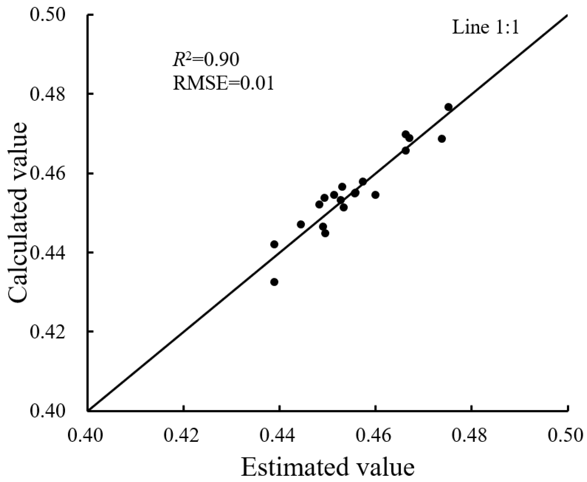
3.3. Construction of Response Surface Model Based on Comprehensive Objective Function

The alteration of the radial clearance width between stator and rotor in the full cross-flow pump unit can affect the hydraulic characteristics of the clearance flow and disturb the flow pattern in the mainstream area of the pump which further affect the overall operational performance of the pump unit and the relationship between the objective function and the influencing factors is highly nonlinear. If the first-order or second-order polynomials were used to fit this nonlinear relationship, it might be difficult to reflect the real relationship, let alone guarantee the fitting accuracy, and the higher-order polynomials might have better fitting results in the calculation domain, but the relevant computational workload could be heavy, along with its complex form, so this was also not adopted. In this paper, the response surface model was applied to fit the data in Table 1 and a cubic polynomial mathematical equation reflecting the influence relationship between the radial inlet clearance width coefficient a/r, the radial outlet clearance width coefficient b/r and Y was established, as shown in Equation (11). For convenience, x1 was adopted to represent a/r and x2 was adopted to represent b/r.
Y = 0.006 x 1 3 + 0.001 x 2 3 + 0.001 x 1 x 2 2 0.055 x 1 2 0.017 x 2 2 0.01 x 1 x 2 + 0.181 x 1 + 0.095 x 2 + 0.175
where x1 is the width coefficient of the radial inlet clearance between stator and rotor; and x2 is the width coefficient of the radial flow clearance between stator and rotor.
The error analysis of the response surface model is shown in Figure 8, in which the distribution of each point was close to the 1:1 line, indicating that the fitting effect was good. The R2 of the integrated objective function was 0.90 and the corresponding RMSE was 0.01, indicating that the model can make a reliable and effective prediction of the test parameters [38].

3.4. Sensitivity Analysis of Radial Clearance Parameters between Stator and Rotor

The sensitivity analysis results of the design parameters of the response surface model are shown in Table 2, where the first-order and overall global sensitivity coefficients were large and the range of coefficients was 0.42 to 0.58. It can be seen that the established response surface model was greatly affected by the alterations of two design parameters, among which the first-order global sensitivity coefficient of the radial inlet clearance width coefficient was larger than that of the radial outlet clearance width coefficient, indicating that the influence of the radial inlet clearance width coefficient on the model established was higher than that of the radial outlet clearance width coefficient. Additionally, the difference between the first-order global sensitivity and the overall global sensitivity coefficient was small and the coefficient difference between the two design parameters was less than 20% of the first-order global sensitivity coefficient, indicating that the interaction between the design parameters was not strong.

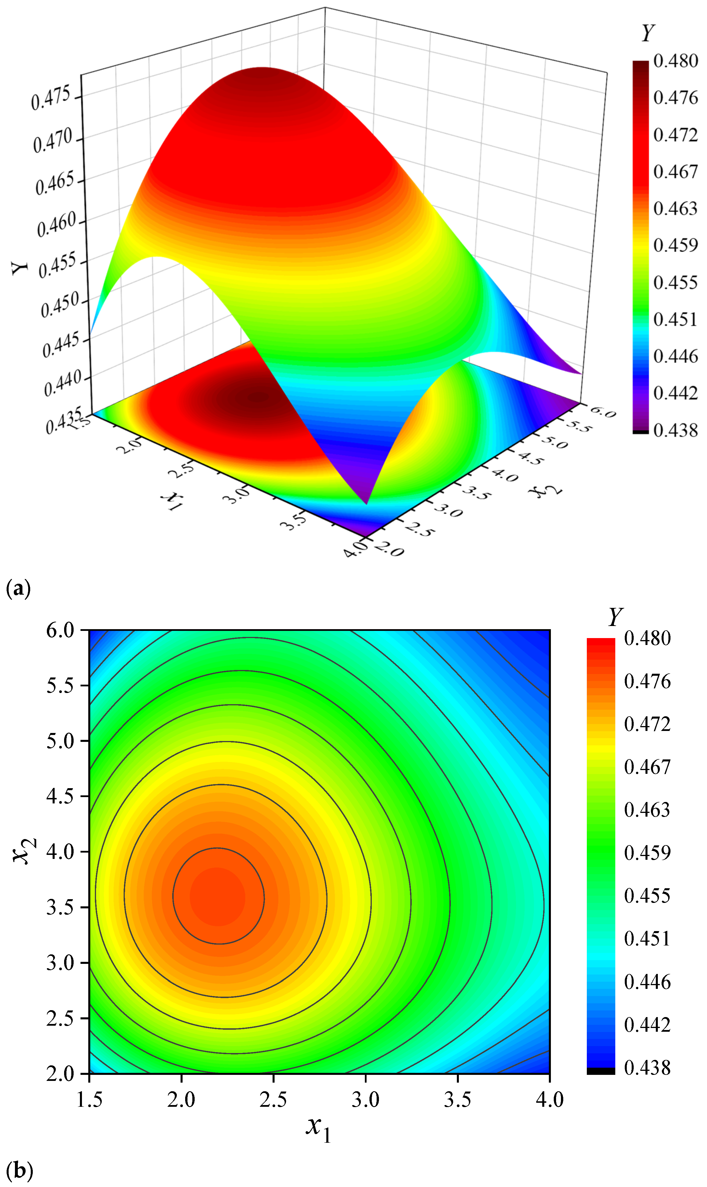
3.5. Analysis of the Influence of Radial Clearance Parameters between Stator and Rotor on Comprehensive Objective Function Based on Response Surface Model

Figure 9 displays the response surface of the radial inlet clearance width coefficient x1 and the radial outlet clearance width coefficient x2 to the objective function. As can be seen from the three-dimensional curved surface cloud map of Figure 9a, generally with the increase of the radial inlet clearance width coefficient x1 and radial outlet clearance width coefficient x2, the objective function Y increased rapidly at first and then descended gradually, with a maximum value in the research range. When x1 was taken between 2.0~2.5 and x2 was taken between 3.2 and 4.0, Y reached higher, and the overall operational performance and internal hydraulic performance of the pump unit were obviously improved. When x1 exceeded 2.5, the response of objective function Y was relatively gentle with the alteration of x2, which first ascended slowly and then decreased slightly with the increase of x2, reflecting that when the radial inlet clearance width between stator and rotor exceeded 2.5r, the performance of the pump unit and the internal flow field first improved and then gradually deteriorated with the increase of the radial outlet clearance width between stator and rotor. In Figure 9b, it can be found that the response contours of the radial inlet clearance width coefficient x1 and the radial outlet clearance width coefficient x2 were similar to a family of concentric circles, with non-strong distortion between the contours which demonstrated that the two factors were not directly coupled and the interaction was not strong. To conclude, the influence position, mode and degree of the inlet and outlet radial clearance width alteration on the internal flow of the pump unit were different and since there is a lack of significant interaction, further independent factor research could be carried out.

3.6. Optimization of Radial Clearance Parameters between Stator and Rotor

In this paper, the radial inlet clearance width coefficient x1 and the radial outlet clearance width coefficient x2 were taken as the independent variables of the optimal design and the synthesis function Y was taken as the objective. The steepest-descent method [39] and the negative gradient were adopted to obtain the minimum value of the comprehensive objective function in the calculation region. Through calculation, the predicted optimization value of the objective function Y was 0.481, in which case x1 was taken as 2.2 and x2 was taken as 3.6. According to the optimization parameters mentioned above, CFD numerical simulation on the optimized scheme was carried out and under this condition, the lift coefficient ψ of the pump unit was 0.16, the efficiency coefficient φ of the pump unit was 0.65, the average radial deflection coefficient μ of the inlet vortex of the outlet channel was 0.96 and the axial velocity uniformity coefficient λ of the outlet section was 0.74, which were all better than the evaluation index value of the selected schemes in this study.

4. Scheme Verification

In order to verify the accuracy of the response surface optimization results based on the information weight method, numerical simulation and physical model tests were carried out. The research model was a full cross-flow pump unit designed with original parameters (x2 = 1, x2 = 1) and modified with the optimized parameters separately, and its operating performance and hydraulic performance were analyzed and compared.

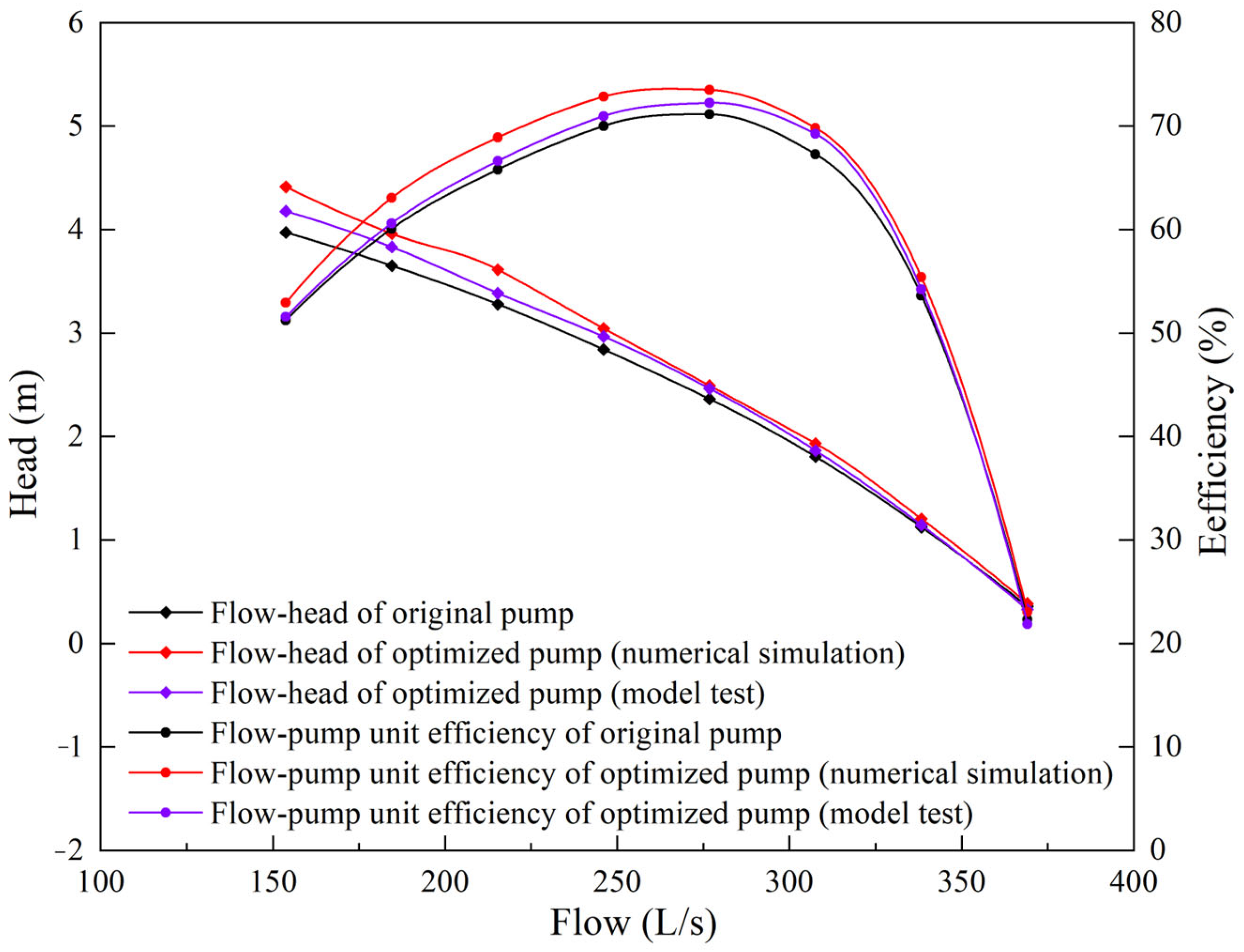
4.1. Operation Performance of Pump Device

The external characteristics of the full cross-flow pump applying the optimized parameters and the original parameters were studied by numerical simulation and physical model test. Taking 0.5Qdes, 0.6Qdes, 0.7Qdes, 0.8Qdes, 0.9Qdes, 1.0Qdes, 1.1Qdes and 1.2Qdes as the characteristic working conditions where Qdes was the design flow in this study, the operational performance of the pump unit under the above seven operating conditions was numerically simulated and tested by physical model, and the operational performance data were calculated and drawn into a curve, as shown in Figure 10.
It can be seen from Figure 10 that when the input flow altered, both the operating performance of original and optimized pump units followed the working law of typical axial-flow pumps and the overall operating performance of the full cross-flow pump unit was obviously improved after parameter optimization. The average lift was about 7.6% higher than that of the original scheme and the optimization effect of the unit efficiency in the high efficiency area was more significant, with the maximum difference of efficiency reaching 5.2%. As a result, it can be found that the radial clearance width parameters optimized by this study combined with the information weight method and response surface optimization have a certain reliability.
By comparing the results of numerical simulations and physical model tests, it was found that the head performance of the pump unit calculated by numerical simulation was about 0.06~0.08 m larger than that of the model test, likewise with the efficiency performance about 1.2~1.4%. The main reason for the error was that there was a certain roughness coefficient in the model unit made by the physical model test, which caused the model pump unit to have a certain amount of head loss during operation. However, in the numerical simulation calculation, the walls of the pump section, the guide vane and the inlet and outlet channels were all set as a smooth wall, which led to the calculation result of the head data being slightly larger than that of the physical model test. In view of the efficiency error, the main reason was that when calculating the device efficiency results of the physical model test, the consumption of no-load was not taken into account, so that there was an efficiency error of about 1.2% to 1.4%.

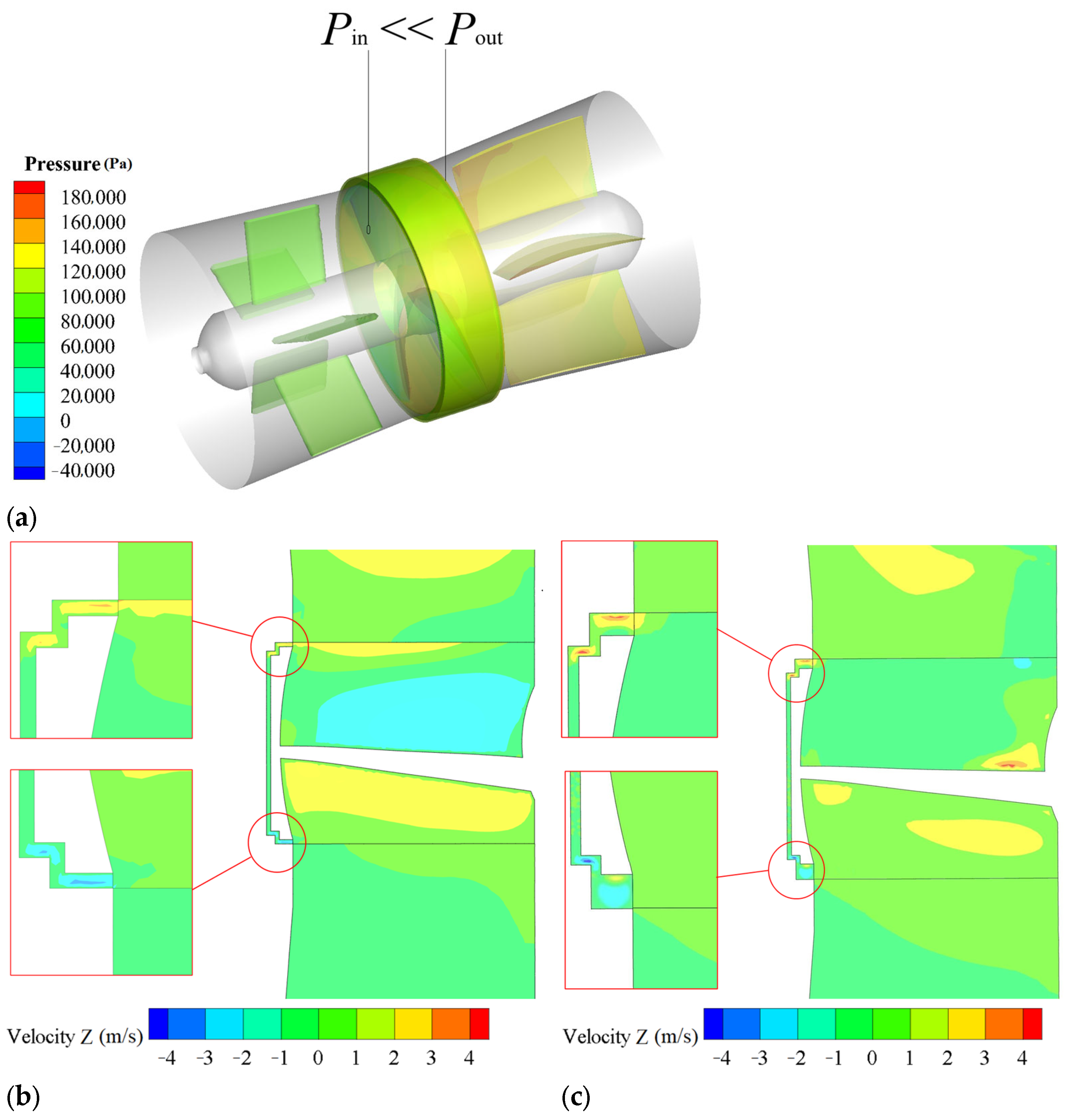
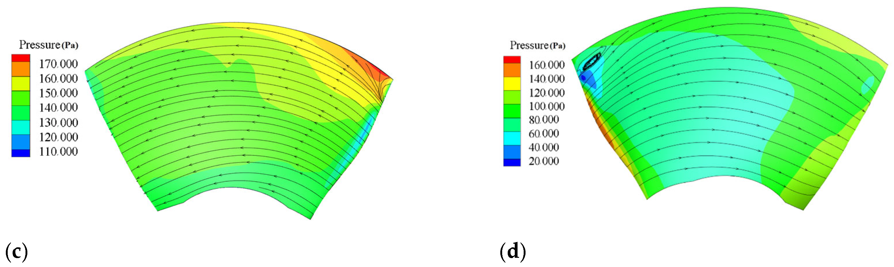
4.2. Internal Flow Characteristics of Pump Unit

To further verify the optimization effect of the optimized radial clearance width parameters between stator and rotor on the hydraulic performance of the pump unit, the internal flow of the pump after its application in the full cross-flow pump unit was analyzed based on the analysis of the formation mechanism of the clearance flow between stator and rotor. The radial velocity distribution in the impeller chamber was selected as the research point and the comparison analysis was made with the samples under original parameters, as shown in Figure 11.
As can be seen from Figure 11a, during the operation of the full cross-flow pump unit, owing to the pressure at the outlet end of the impeller chamber being much larger than that at the inlet end, part of the flow flowed back from the outlet end of the impeller chamber to the inlet end through the clearance between stator and rotor, leading to the forming of backflow between stator and rotor and injecting into the inlet side of the impeller chamber along the tangent direction of the stator and rotor clearance outlet section. Combined with Figure 11b, it can be demonstrated that on the inlet side of the clearance between stator and rotor, due to the large pressure in the mainstream region, there was an obvious pressure gradient in the axial clearance between the stator and rotor and the clearance width under the original scheme was narrow. Therefore, the partial flow was sucked into the clearance at a great transverse velocity, forming an obvious transverse velocity zone at the outlet of the impeller chamber, which inevitably disturbed the mainstream of the pump. On the outflow side of the clearance between the stator and rotor, due to the small mainstream pressure, the reverse pressure gradient between the mainstream and the clearance flow was not enough to mix the clearance flow into the mainstream in the form of a jet, resulting only in a local low transverse velocity zone in the mainstream region. As can be seen from Figure 11c, the inlet and outlet speeds of the clearance flow between the stator and rotor were obviously reduced during the operation of the pump unit after parameter optimization. Due to the increase of the width of the radial clearance, part of the axial mainstream water and the radial water in the clearance collided were mixed with each other and the turbulent energy was transferred to the clearance between stator and rotor gradually, so that the long transverse velocity region of the original mainstream area had to be compressed, which reduced the disturbance of the clearance flow to the mainstream area.
Figure 12 shows the pressure and streamline distribution of the blade pressure surface and suction surface and it can be found that after parameter optimization, the area of the local sector high-pressure zone on the flange side of the inlet end of the impeller pressure surface decreased obviously, indicating that the hydraulic performance of the clearance flow at the inlet end of the pump impeller chamber near the flange had been optimized. The fitting of the flow route and the blade angle around it had been improved and, to a certain extent, the impact inflow phenomenon between the flow and the impeller was reduced, thus cutting off the energy loss of the blade. On the suction surface of the impeller, the area of the local low-pressure region on the inlet side of the impeller under the optimization scheme was much smaller than that of the original scheme, indicating that the cavitation phenomenon in this area was also improved during the actual operation of the impeller.
Figure 13 shows the flow field diagram of the middle section of the outlet conduit and it can be found that there was still a part of residual circulation in the original scheme after the guide vane rectification, so that the water body still had the phenomenon of bias flow when it entered the outlet channel. After the optimization of the radial clearance parameters between stator and rotor, the flow entered the outlet channel in a relatively smooth state and flowed evenly and the velocity-weighted average vortex angle of the inlet section of the outlet channel was only 4.0°, about 11.2% better than that of the original scheme. The comprehensive results showed that the radial clearance width parameters between the stator and rotor optimized in this study can reduce the disturbance of the clearance flow to the mainstream flow pattern in the impeller chamber of the full cross-flow pump unit, decreasing the amount of export circulation of the guide vane body, thus the flow enters the outlet channel in a relatively smooth flow pattern.

5. Discussion

Firstly, Shi et al. 13 improved the hydraulic performance of the full cross-flow pump by optimizing the length of the outer rotor cavity. Meng et al. [10] improved the energy performance of the full cross-flow pump unit by optimizing the intermediate clearance width of the stator–rotor. Jiao et al. [4] improved the hydraulic transition performance of the full cross-flow pump by optimizing the rotor angle. A series of relevant studies have all considered the radial structure of full cross-flow pump units as symmetric, but through the analysis and research in this paper, the parameter design of the radial inlet clearance had a higher impact on the performance of the unit than that of the radial outlet clearance design. Therefore, it is recommended to design these kinds of models as asymmetric in subsequent full cross-flow pump unit optimization research and a higher influence weight ratio should be given to the inlet clearance of the stator–rotor.
Secondly, both excessively wide and narrow inlet and outlet clearance widths will aggravate the disturbance of clearance flow to the flow field of the impeller chamber, and when the unit is operating the cooling effect of clearance flow on the motor should also be considered; that is, excessively narrow clearance widths will not only increase the energy loss of the unit but also shorten the service life of the motor.
Lastly, for the full cross-flow pump unit, the reason why its efficiency is significantly lower than that of the semi cross-flow pump is not only the disturbance from the stator–rotor clearance flow on the flow field of the impeller chamber, but also the large dynamic friction loss; that is, the disk friction power between the contact part of the rotor outer edge and the clearance reflux, which can increase the rotor torque, leading to the energy loss of the motor. In this paper, the hydraulic performance of the clearance flow field was taken as the main research object, and the mechanism of its influence on the performance of the unit was analyzed. In reference [10], the rotor torque was calculated and the influence of clearance flow on the energy dissipation of the impeller chamber was analyzed based on the theory of entropy production. Therefore, as to further optimize the operating efficiency of the full-flow pump unit, comprehensive improvement in the hydraulic characteristics and energy characteristics of the stator–rotor clearance is the key point that needs to be explored in the future.

6. Conclusions

In this study, with the application of hydrodynamics technology, based on the information weight method and the response surface model, the functions between the width coefficient of radial inlet clearance between stator and rotor, the width coefficient of radial outlet clearance, the operational performance and the hydraulic performance of full cross-flow pumps were studied. The relevant conclusions were as follows:
(1) The information weight method can comprehensively consider several evaluation indexes of the external and internal flow characteristics of the full cross-flow pump unit and by forming a comprehensive objective function, the optimization effect of the radial clearance design between stator and rotor on the operation and hydraulic performance of the pump unit can be expressed quantitatively, with reliable optimization results.
(2) Taking width coefficients of the radial inlet and outlet clearance between stator and rotor as design parameters, through the response surface optimization analysis and the steepest-descent method, the optimal parameter combinations were as follows: the inlet clearance width coefficient x1 was 2.2 and the outlet clearance width coefficient x2 was 3.6, in which case the comprehensive objective function Y can be predicted to reach 0.481.
(3) Based on the optimal parameter combination of the radial clearance width between stator and rotor, the head of the full cross-flow pump unit was about 7.6% higher than that of the original scheme and the optimization effect of the unit efficiency in the high efficiency area was more obvious, with its maximum value reaching 5.2%, and the inlet and outlet velocity of clearance were significantly reduced. The optimization of the radial clearance width parameters between stator and rotor can reduce the disturbance of the clearance flow to the mainstream flow pattern in the impeller chamber of the full cross-flow pump unit, decreasing the amount of export circulation of the guide vane body, thus the flow enters the outlet channel in a relatively smooth flow pattern.
(4) The response of the width coefficient of the radial inlet and outlet clearance between stator and rotor to the comprehensive objective function was indirect coupling and the interaction was not strong. Then, the influence position, mode and degree of the inlet and outlet radial clearance width alteration on the internal flow of the pump unit were different and the shadow response degree of the radial inlet clearance width coefficient x1 to the model was higher than that of the radial outlet clearance width coefficient x2, indicating that further independent factor research could be conducted and that such kinds of models are more suitable to be designed as asymmetric in subsequent full cross-flow pump unit optimization research, where a higher influence weight ratio should be given to the inlet clearance.

Author Contributions

J.L.: writing, review, editing and visualization. W.L.: funding acquisition, software, labs and methodology. W.X.: validation. All authors have read and agreed to the published version of the manuscript.

Funding

This research was funded by Water Conservancy Technology Foundation of Jiangsu Provincial of China (2020060); Postgraduate Research and Practice Innovation Program of Jiangsu Province (Yangzhou University) (KYCX24_3754); Research and Development Project of Jiangsu South to North Water Diversion Technology of China (JSNSBD202302).

Institutional Review Board Statement

Not applicable.

Informed Consent Statement

Not applicable.

Data Availability Statement

Data is contained within the article.

Conflicts of Interest

The authors state that they have no known competing financial interests or personal relationships that could affect the work described in this article.

References

  1. Buono, D.; Frosina, E.; Mazzone, A.; Cesaro, U.; Senatore, A. Study of a pump as turbine for a hydraulic urban network using a tridimensional CFD modeling methodology. Energy Procedia 2015, 82, 201–208. [Google Scholar] [CrossRef]
  2. Rossi, M.; Comodi, G.; Piacente, N.; Renzi, M. Effects of viscosity on the performance of Hydraulic Power Recovery Turbines (HPRTs) by the means of Computational Fluid Dynamics (CFD) simulations. Energy Procedia 2018, 148, 170–177. [Google Scholar] [CrossRef]
  3. Shirazi, A.; Nazari, M.; Manshadi, M. Numerical and experimental investigation of the fluid flow on a full-scale pump jet thruster. Ocean Eng. 2019, 182, 527–539. [Google Scholar] [CrossRef]
  4. Jiao, H.; Shan, J.; Yang, G.; Wang, M.; Chen, S. Comparison of the Shutdown Transitions of the Full-Flow Pump and Axial-Flow Pump. J. Mar. Sci. Eng. 2023, 11, 2129. [Google Scholar] [CrossRef]
  5. Shi, L.; Zhang, W.; Jiao, H.; Tang, F.; Wang, L.; Sun, D.; Shi, W. Numerical simulation and experimental study on the comparison of the hydraulic characteristics of an axial-flow pump and a full tubular pump. Renew. Energy 2020, 153, 1455–1464. [Google Scholar] [CrossRef]
  6. Shi, L.; Jiang, Y.; Cai, Y.; Chen, B.; Tang, F.; Xu, T.; Zhu, J.; Chai, Y. Influence of inlet groove on flow characteristics in stall condition of full-tubular pump. Front. Energy Res. 2022, 10, 949639. [Google Scholar] [CrossRef]
  7. Sekar, K.; Kumar, N.; Vasanthakumar, P. Centrifugal pump as turbine for micro-hydro power scheme in rural areas of India: A review. Int. J. Chem. Tech. Res. 2017, 10, 106–109. [Google Scholar]
  8. Wang, C.; Zhao, C.; Zhang, T.; Liu, D. The numerical simulation of full flow field of Roto-Jet pump and analysis of energy losses. Adv. Mater. Res. 2012, 562, 1369–1372. [Google Scholar]
  9. Shi, L.; Zhu, J.; Wang, L.; Chu, S.; Tang, F. Comparative analysis of strength and modal characteristics of a full tubular pump and an axial flow pump impellers based on fluid-structure interaction. Energies 2021, 14, 6395. [Google Scholar] [CrossRef]
  10. Meng, F.; Li, Y.; Pei, J. Energy characteristics of full tubular pump unit with different backflow clearances based on entropy production. Appl. Sci. 2021, 11, 3376. [Google Scholar] [CrossRef]
  11. Shi, L.; Yuan, Y.; Jiao, H.; Tang, F.; Cheng, L.; Yang, F.; Zhu, J. Numerical investigation and experiment on pressure pulsation characteristics in a full tubular pump. Renew. Energy 2021, 163, 987–1000. [Google Scholar] [CrossRef]
  12. Xu, X. Research and Optimization Design of Maxwell Based Full Throughflow Pump Motor Characteristics. Master’s Thesis, Yangzhou University, Yangzhou, China, 2022. (In Chinese). [Google Scholar]
  13. Shi, L.; Zhu, J.; Li, J.; Tang, F.; Chen, B.; Jiang, Y.; Xu, T.; Chai, Y. Flow characteristics and optimization design of the stator–rotor cavity of the full tubular pump. Processes 2022, 10, 1688. [Google Scholar] [CrossRef]
  14. Xu, B.; Liu, J.; Lu, W.; Xu, L.; Xu, R. Design and Optimization of γ-Shaped Settlement Training Wall Based on Numerical Simulation and CCD-Response Surface Method. Processes 2022, 10, 1201. [Google Scholar] [CrossRef]
  15. Brunelli, C.; Castellani, F.; Garinei, A.; Biondi, L.; Marconi, M. A procedure to perform multi-objective optimization for sustainable design of buildings. Energies 2016, 9, 915. [Google Scholar] [CrossRef]
  16. Wang, Y.; Lin, Z.; Lei, X.; Li, X.; Liu, S.; Liu, Y. Correlation development and parametric investigation for thermal–hydraulic characteristics of flying-wing fin. Appl. Therm. Eng. 2023, 219, 119445. [Google Scholar] [CrossRef]
  17. Sangsefidi, Y.; MacVicar, B.; Ghodsian, M. Evaluation of flow characteristics in labyrinth weirs using response surface methodology. Flow Meas. Instrum. 2019, 69, 101617. [Google Scholar] [CrossRef]
  18. Peng, C.; Zhang, X.; Gao, Z.; Ju, W.; Yan, G. Research on cooperative optimization of multiphase pump impeller and diffuser based on adaptive refined response surface method. Adv. Mech. Eng. 2022, 14, 16878140211072944. [Google Scholar]
  19. El-Hadj, A.; Abd-Rahim, S. Optimization of an external gear pump using response surface method. J. Mech. 2020, 36, 567–575. [Google Scholar] [CrossRef]
  20. Velásquez, L.; Posada, A.; Chica, E. Optimization of the basin and inlet channel of a gravitational water vortex hydraulic turbine using the response surface methodology. Renew. Energy 2022, 187, 508–521. [Google Scholar] [CrossRef]
  21. Capurso, T.; Bergamini, L.; Camporeale, S.; Fortunato, B.; Torresi, M. CFD analysis of the performance of a novel impeller for a double suction centrifugal pump working as a turbine. In Proceedings of the 13th European Conference on Turbomachinery Fluid dynamics & Thermodynamics, Lausanne, Switzerland, 8–12 April 2019. [Google Scholar]
  22. Zong, Z.; Rui, W.; Lu, L.; Huang, X. Experimental investigation of broadband thrust and loading noise from pump jet due to turbulence ingestion. Ocean Eng. 2022, 255, 111408. [Google Scholar]
  23. Shahabi, M.; Ahadiyan, J.; Ghomeshi, M.; Narimousa, M.; Katopodis, C.; Nadian, H. Numerical study of the effect of a V-shaped weir on turbulence characteristics and velocity in V-weir fishways. River Res. Appl. 2023, 39, 21–34. [Google Scholar] [CrossRef]
  24. Mavrakos, A.; Konispoliatis, D.; Ntouras, D.; Papadakis, G.; Mavrakos, S. Hydrodynamic coefficients in heave of a moonpool-type floater using theoretical, numerical and CFD methodologies. Ocean Eng. 2023, 279, 114519. [Google Scholar] [CrossRef]
  25. Khanarmuei, M.; Rahimzadeh, H.; Sarkardeh, H. Effect of dual intake direction on critical submergence and vortex strength. J. Hydraul. Res. 2019, 57, 272–279. [Google Scholar] [CrossRef]
  26. Lv, Y.; Li, S.; Wang, Z.; Zhou, L. Study on pump mode cavitation characteristic of variable speed pump turbine. Phys. Fluids 2023, 35, 065111. [Google Scholar]
  27. Simão, M.; Pérez-Sánchez, M.; Carravetta, A.; Ramos, H. Velocities in a centrifugal PAT operation: Experiments and CFD analyses. Fluids 2017, 3, 3. [Google Scholar] [CrossRef]
  28. Jiao, H. Research on Hydraulic Performance and Throttling Radial Gap Size of Full Throughflow Pump. Master’s Thesis, Yangzhou University, Yangzhou, China, 2020. (In Chinese). [Google Scholar]
  29. Shibata, M.; Kawashima, T.; Yamashita, M.; Kawato, S. Theoretical analysis of a high efficiency blue-laser-diode-pumped Ti: Sapphire laser by high intensity pumping. Laser Phys. Lett. 2021, 18, 105001. [Google Scholar] [CrossRef]
  30. Hu, C.; Lang, J.; Xie, Y. Pumping performance analysis of negative ion based neutral beam injector cryosorption pump prototype. Fusion Eng. Des. 2023, 189, 113469. [Google Scholar] [CrossRef]
  31. Zhao, Y.; Zhang, P.; Pu, Y.; Lei, H.; Zheng, X. Unit Operation Combination and Flow Distribution Scheme of Water Pump Station System Based on Genetic Algorithm. Appl. Sci. 2023, 13, 11869. [Google Scholar] [CrossRef]
  32. Chang, L.; Xu, Q.; Yang, C.; Su, X.; Dai, X.; Guo, L. Experimental Study on Gas–Liquid Performance and Prediction of Shaft Power and Efficiency by Dimensionless Coefficients in a Multistage Electrical Submersible Pump. J. Fluids Eng. 2023, 145, 071204. [Google Scholar] [CrossRef]
  33. Li, Z.; Yang, J. Filtering Feature Selection Algorithm Based on Entropy Weight Method. J. Northeast. Univ. (Nat. Sci.) 2022, 43, 921–929. [Google Scholar]
  34. Husnain, T.; Duan, H.; Mark, O. Global sensitivity analysis of bioretention cell design for stormwater system: A comparison of VARS framework and Sobol method. J. Hydrol. 2023, 617, 128895. [Google Scholar]
  35. Cao, X.; Feng, D. A direct analytical derivation of the multi-dimensional fragility spaces of structures under nonstationary mainshock-multi-aftershock sequences. Probabilistic Eng. Mech. 2024, 76, 103630. [Google Scholar] [CrossRef]
  36. Yang, D.; Lian, J.; Zhao, X.; Hou, Q.; Chen, Y.; Zhang, Y. A mathematical model for supercooling process and its application to frazil ice evolution. Sci. Rep. 2023, 13, 5801. [Google Scholar] [CrossRef] [PubMed]
  37. Liu, J. Optimization Study on the Hydrodynamic Characteristics of the Clearance between the Stator and Rotor of a Full through Flow Pump Device. Master’s Thesis, Yangzhou University, Yangzhou, China, 2023. (In Chinese). [Google Scholar]
  38. Zoratipour, E.; Mohammadi, A.; Zoratipour, A. Evaluation of SEBS and SEBAL algorithms for estimating wheat evapotranspiration (case study: Central areas of Khuzestan province). Appl. Water Sci. 2023, 13, 137. [Google Scholar] [CrossRef]
  39. He, S.; Zhang, W.; Yin, T. Inexact projection contraction method and hybrid steepest descent method for inverse variational inequalities. J. Nonlinear Convex Anal. 2022, 23, 2763–2774. [Google Scholar]
Figure 1. Schematic diagram of calculation area.
Jmse 12 01124 g001
Figure 2. Schematic diagram of grid division for each part of full cross-flow pump section.
Jmse 12 01124 g002
Figure 3. Local grid details of the full cross-flow pump unit are as follows: (a) Front vane; (b) Rear vane; (c) Impeller; (d) Outer ring; (e) Outer ring radial section.
Jmse 12 01124 g003
Figure 4. Grid independence calculation diagram.
Jmse 12 01124 g004
Figure 5. Photo of the pump unit model.
Jmse 12 01124 g005
Figure 6. Schematic diagram of the geometric parameters of inlet clearance and outlet clearance of a full cross-flow pump.
Jmse 12 01124 g006
Figure 7. Flow chart of the establishment of the response surface model by the information weight method.
Jmse 12 01124 g007
Figure 8. Error analysis of comprehensive objective function Y estimated by the response surface model.
Jmse 12 01124 g008
Figure 9. Influence diagram of width coefficients of radial inlet and outlet clearance width between stator and rotor on comprehensive objective function. (a). Three-dimensional surface cloud picture. (b). Response contour cloud map. Note: x1 represents a/r, x2 represents b/r.
Jmse 12 01124 g009
Figure 10. Comparison of operating performance curve of full cross-flow pump unit.
Jmse 12 01124 g010
Figure 11. Distribution of pressure and radial velocity of flow in the pump unit. (a). Pressure distribution diagram in pump; (b). Radial velocity distribution (original scheme); (c). Radial velocity distribution (optimization scheme).
Jmse 12 01124 g011
Figure 12. Pressure and streamline distribution of blade pressure surface and suction surface. (a). Pressure surface of impeller (original scheme); (b). Suction surface of impeller (original scheme); (c). Pressure surface of impeller (optimization scheme); (d). Suction surface of impeller (optimization scheme).
Jmse 12 01124 g012aJmse 12 01124 g012b
Figure 13. Flow field diagram of the middle section of the outlet channel. (a). Flow field diagram of characteristic cross section of outlet channel (original scheme); (b). Flow field diagram of characteristic cross section of outlet channel (optimization scheme).
Jmse 12 01124 g013
Table 1. Numerical simulation results of the radial clearance parameter between stator and rotor of full cross-flow pump.
Scheme Serial NumberDesign ParametersψφμλY
ab
12r6r0.150.600.930.700.454
22r5r0.150.620.950.730.466
32r4r0.160.640.960.730.477
42r3r0.150.620.960.720.469
52r2r0.150.590.940.720.458
63r6r0.140.590.920.690.445
73r5r0.150.600.930.710.455
83r4r0.160.620.950.730.469
93r3r0.160.600.950.730.470
103r2r0.150.590.940.710.457
114r6r0.140.590.920.690.442
124r5r0.140.600.920.700.447
134r4r0.140.620.920.700.454
144r3r0.140.600.920.690.446
154r2r0.130.590.910.660.432
165r6r0.140.600.930.700.453
175r5r0.140.600.930.700.451
185r4r0.150.600.930.710.455
195r3r0.150.600.920.710.455
205r2r0.150.590.930.700.452
216r6r0.080.550.910.63
226r5r0.090.560.910.62
236r4r0.090.560.910.60
246r3r0.080.570.900.59
256r2r0.080.560.910.60
Standard deviation0.010.010.010.02
Coefficient of variation0.050.020.010.02
Information weight0.470.190.130.21
Note: a is the width of the radial inlet clearance between stator and rotor; b is the width of the radial outlet clearance between stator and rotor; r is the width of the intermediate clearance between stator and rotor; ψ is the head coefficient of the pump unit; φ is the efficiency coefficient of the pump unit; μ is the average radial deflection coefficient of vortex at the inlet section of the outlet channel; λ is the axial velocity uniformity coefficient of the outlet section; Y is the comprehensive objective function. Same as below.
Table 2. Sensitivity analysis of radial clearance parameters between stator and rotor.
Design ParameterFirst-Order Global Sensitivity CoefficientOverall Global Sensitivity CoefficientCoefficient Difference
Width coefficient of radial inlet clearance between stator and rotor x10.500.590.09
Width coefficient of radial outlet clearance between stator and rotor x20.410.500.09
Disclaimer/Publisher’s Note: The statements, opinions and data contained in all publications are solely those of the individual author(s) and contributor(s) and not of MDPI and/or the editor(s). MDPI and/or the editor(s) disclaim responsibility for any injury to people or property resulting from any ideas, methods, instructions or products referred to in the content.

