Review

Recent Progress on Built-in Wave Energy Converters: A Review

1
Dalian Key Lab of Marine Micro/Nano Energy and Self-Powered System, Dalian Maritime University, Dalian 116026, China
2
Shanghai Investigation, Design & Research institute Co., Ltd., Shanghai 200335, China
*
Authors to whom correspondence should be addressed.
J. Mar. Sci. Eng. 2024, 12(7), 1176; https://doi.org/10.3390/jmse12071176
Submission received: 15 June 2024 / Revised: 10 July 2024 / Accepted: 10 July 2024 / Published: 13 July 2024
(This article belongs to the Special Issue The 10th Anniversary of JMSE - Review Collection)

Abstract

:
A built-in wave energy converter (BI-WEC) is a type of WEC that is fully encapsulated within a floating body that is easy to integrate and promotes reliability. Significant advantages in integration and reliability make BI-WECs a promising pathway to achieve an in situ power supply for massive distributed marine equipment (such as ships, buoys, or USVs). A comprehensive review of the recent advances in built-in wave energy converters can help address the most relevant issues in BI-WEC development. This study enumerates recent progress on BI-WECs (energy capture, power take-off, and control) and summarizes the characteristics of various designs. Different design philosophies and technical pathways can be better understood through the classification and analysis offered by this study. This review helps to form a basic understanding of BI-WEC development to achieve in situ power sustainability for a large amount of distributed marine equipment in long-term sustained marine operations.

1. Introduction

Floating/submerged buoys [1], unmanned surface vehicles [2], marine robotics [3], and disposable devices [4] are important types of marine equipment in the development of ocean study and research. Concurrent power supplies largely rely on batteries, fuel storage, or cables, which have a hard time fulfilling long-term sustained marine operations [5,6]. It has been recognized that the energy supply has formed a major bottleneck in the performance of marine equipment. Taking advantage of extensively distributed marine renewable energy could fundamentally address the power supply conundrum [7,8]. Compared with other possible power sources (e.g., wind, solar, and thermal differential power), wave energy is a promising pathway toward realizing an in situ power supply [9].
Wave power is superior in its power density, consistency, and engineering practicability. Wave energy generally has a higher energy flow per unit area (estimated at 2–3 kW/m2) than that of wind energy (at 0.4–0.6 kW/m2) or solar energy (at 0.1–0.2 kW/m2) [10]. Some buoys carrying hybrid wave–solar power systems have recorded that wave power could be more than two times greater than solar power, and this advantage becomes more evident in winter. Wave energy can be accessible for 90% of each day, while solar energy may only cover less than 30% of a day, which reduces the power management burden [11]. Wave energy converters have lower requirements for vertical dimensions (in comparison, e.g., with wind energy devices) and horizontal dimensions (in comparison, e.g., with solar energy devices), making them more compact and less vulnerable as floating structures from their first principles [12].
Up to now, wave power technologies for distributed marine equipment have achieved considerable progress. Ocean Power Technologies Inc. developed a wave-powered surface surveillance solution equipped with a high-definition radar, gyro-stabilized optical and thermal imaging cameras, vessel automatic identification system (AIS) detection, and integrated command and control software, and it could be used to monitor more than 1600 square miles of the ocean surface [13]. Wave gliders developed by Shanghai Jiaotong University have integrated a wave–solar hybrid power supply system that increases the glider’s “self-power” by two to three times (compared with solar power only) [14]. For comprehensive marine observations, the required daily consumption is estimated to be no less than 3 kWh (the current solar power on observation buoys is generally below 1 kWh). The gap can hardly be filled if solar energy is taken as the only power supply. Considering its power density, consistency, and engineering practicability, wave power is likely to be part of the solution.
Different demands give rise to different philosophies for wave power technologies. The WECs for the general grid are power plants; therefore, their hydrodynamic design (geometry) targets optimal energy capture, and their power take-off targets optimal electricity generation. The wave power technology for distributed marine systems places more emphasis on ease of integration (i.e., reducing changes in the carrier) under the premise that the carrier’s power supply requirements can be met [15]. This design philosophy fits the characteristics of the built-in wave energy converter (BI-WEC) very well. A BI-WEC is placed as a whole inside its carrier, and it is the relative (wave-driven) motion between the main body of the carrier and the built-in inertial body that drives the power take-off [16]. BI-WECs possess a remarkable advantage in that, as a built-in module, they can be integrated into various types of marine equipment quite easily [8,17]. In addition, as a whole, BI-WEC is encapsulated inside its carrier; its transmission and connection structures are not subject to direct impact, seawater corrosion, or marine growth, which could significantly promote the reliability of BI-WEC systems [18].
With their unique advantages (integration and reliability), BI-WECs are gaining prominence. A few prototypes have been sea-trialed, demonstrating good applicability [19,20], while some challenges have also been observed (such as adaptivity) [21,22]. Therefore, it is time to collect, analyze, and summarize pieces of progress in various aspects so that BI-WEC developers can easily find where we stand and identify what the real problems are. Following the usual workflow of designing a BI-WEC, the context is organized as wave energy capture, power take-off (PTO), controls, and conclusions.

2. Wave Energy Capture

The working process of a WEC, roughly speaking, consists of “capturing” and “converting”. The former involves the capture of wave energy such that the mechanical energy of the waves is “captured” and passed on to the PTO, while the latter involves the conversion of mechanical energy into electricity. In energy capture, most WECs have either an oscillating body design (subdivided into a single body or multiple bodies) or an oscillating water column design [23]. Statistics from China indicate that most sea-trialed prototypes use these designs [24]. A qualitative comparison among the (mainstream) energy-capturing pathways is given in Table 1.
Oscillating water column-type devices capture wave energy using fluid as a medium, thus keeping the collocated air turbine and generator clear from seawater. Japan’s Masuda navigational buoy adopted the oscillating water column (OWC) mechanism, and it is considered the first practical form of marine equipment to be powered by wave energy [25]. The Dalian University of Technology has developed a series of methodologies for systematically promoting energy-capturing efficiency, such as multi-chamber designs, wave concentration techniques, and array arrangements [26,27]. The BD (abbreviation for “wave electricity” in Chinese) series OWC device developed by the Guangzhou Institute of Energy Conversion, Chinese Academy of Science, is considered the first Chinese WEC product, and it has been applied to a series of ocean observation devices [28]. However, to capture wave energy, the OWC requires an air chamber, a water cabin, and seawater to be successively connected. Openings are required both above and below the waterline. From an engineering perspective, this configuration should be designed in the beginning, which makes it more difficult to integrate this OWC as a module into many carriers.
Table 1. A comparison of energy-capturing pathways.
Oscillating Water Column Type [29]Oscillating Body Type (Two Bodies/Multiple Bodies) [30]Oscillating Body Type (Single Body, Pull-Out Mooring Required) [31]Oscillating Body Type (Single Body, Fully Encapsulated) [32]
Jmse 12 01176 i001Jmse 12 01176 i002Jmse 12 01176 i003Jmse 12 01176 i004
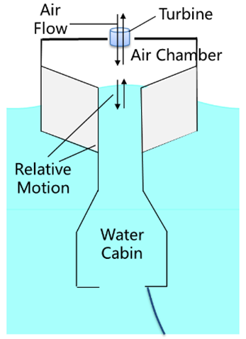
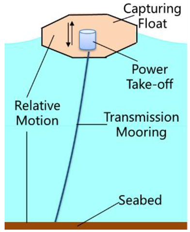
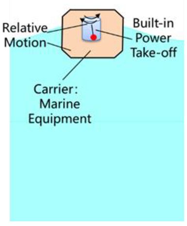
1. It is necessary to connect the air chamber, water compartment, and seawater successively;
2. Openings are required both above the waterline and below the waterline.
1. Two or more floating bodies are required;
2. Transmission/connecting structures partially contact seawater directly.
1. It is required to connect to an anchoring (fixed) point;
2. Transmission/connecting structures partially contact seawater directly.
1. Completely integrated into its carrier as an internal module;
2. Transmission/connecting structure does not contact seawater directly.
Alternatively, if it is the relative motion between a main float and a (wave-capturing) float that drives the generator, the WEC itself will become a two-body structure or even a multi-body structure (e.g., the PB3 from Ocean Power Technologies [33]). In this sense, it is quite natural that most WECs are either oscillating bodies or oscillating water columns, depending on what the energy-capturing medium is (a rigid body for OBs or fluid for OWCs). Essentially, there must be some relative motion to drive the PTO; an oscillating body utilizes the relative motion between rigid bodies, while an oscillating water column utilizes the relative motion between a rigid body and a fluid. However, it can be easily understood that a two-body structure or multi-body structure can significantly alter the original configuration of distributed marine equipment (e.g., a buoy or an unmanned surface vehicle).
If it is the relative motion between the capturing float and the fixed point (e.g., the seabed) that drives the PTO, the whole WEC can be made as a single body. A good example is AquaHarmonics, which won first place in the Wave Energy Prize hosted by the U.S. Department of Energy [27]. AquaHarmonics possesses an optimized geometry (single body) moored (through a tether) to the seabed. As waves pass by, the device rises and falls on them, and the generator spins through the (mooring) tether. As can be seen, this type of device requires a fixed point to capture wave energy, which is incompatible with the tasks of many types of marine equipment (e.g., USVs). More importantly, the transmission and connection structures of two-body/multi-body (oscillating body type) WECs are inevitably exposed to seawater, which accounted for most of the failures/damage in previous sea trials.
Thus, these common WEC designs influence the design of their carriers, making it difficult to directly integrate the WECs into distributed marine systems [34]. The BI-WEC is a special type of single-oscillating-body WEC. With the converter being completely arranged inside the carrier, it has a minimal influence on the carrier [35]. A boat-shaped hull (slack-moored) has been adopted for inertial sea wave energy converters (ISWECs). The built-in spinning gyroscopic system mainly converts the pitch motion (which is enhanced by the optimized hull design) into electricity [19,22,36,37]. The Penguin wave energy device developed in Finland bears a 44 m asymmetrical hull designed to capture wave energy from the variations in azimuth. The hull is designed to be non-axisymmetric so that incident waves drive the Penguin to roll, pitch, and yaw, creating relative rotation between the hull and the internal PTO (a horizontal pendulum) and capturing the energy from incoming waves [20]. Sea trials for these prototypes have shown that the “built-in” concept noticeably reduces the probability of damage (as the WECs are placed inside), demonstrating the BI-WEC’s unique advantage in terms of reliability.
A spherical geometry was adopted for GyroPTO, and the relative roll and pitch between the body and the internal PTO gives rise to a gyroscopic moment driving the generator [38]. Similarly, a spherical geometry was adopted for WITT, and a heavy-chain catenary mooring system was integrated to help achieve device resonances. Though mooring is important in its design, it does not serve as a transmission part of the WEC; therefore, the WEC is still fully encapsulated in the hull [39]. The geometry of SEAREV is similar to that of a mushroom from its side view, and it mainly consists of two parts: a floating part with optimized geometry and a fully submerged part containing a horizontal axis with a heavy pendulum inside (the core of its PTO) [40]. The geometry of PS Frog Mk 5 consists of a large buoyant paddle with a ballasted handle hanging below it [41]. These two devices are similar in that they both mainly aim to capture the pitch motion excited by waves, though a horizontal relative sliding PTO is adopted in PS Frog Mk 5. Zhou et al. modified the bottom geometry of the floater with a Berkeley Wedge so that the viscous damping in heaving motion (an effective degree of freedom) could be minimized [42]. Texas A&M University developed a surface-riding BI-WEC using a slender horizontal cylinder (to carry a sliding-mode PTO inside), while it mainly captures the pitch motion [43].
Many countries (especially China) are located near relatively mild seas with a low wave height compared to that in the North Atlantic Ocean close to Europe [44]. Therefore, many Chinese researchers tend to consider BI-WECs as self-powering techniques for marine equipment. Jing and Zheng from Harbin Engineering University characterized the major technical features of built-in wave energy converters and referred to them (in Chinese) as a WEC type that “(internally) follows the main body” (literally) [45]. Others referred to the BI-WEC as an “internally placed” WEC or inertial WEC. They describe the same thing from different perspectives. Zheng developed a BI-WEC to fit into a common (large-scale) observation buoy. The buoy geometry was not greatly modified, demonstrating the concept of minimum changes to the carrier being made due to the BI-WEC. It is the heave motion captured by the buoy that drives the built-in PTO [46].
The BI-WEC developed by Soochow University is also integrated into an existing ocean buoy (axisymmetric). With a built-in horizontal pendulum, when captured effectively, the roll and pitch (as well as yaw) motions drive the relative rotation between the buoy and the generator, which is similar to the Penguin WEC [35]. The Qingdao University of Science and Technology designed a BI-WEC for merchant vessels so that the dominant rolling motion could be captured as a source of power supply [47]. The University of Southampton investigated a feasible pathway to realize a wave-powered (comparable to equivalent solar panels) AUV, which mainly considers the pitch mode [48]. The efficiency of energy capture is largely determined by the hydrodynamic response of the WEC. Therefore, a traditional pathway for promoting WEC performance is shape design and (geometric) parameter optimization, which is evident from the studies by Clemente et al. [49,50]. The energy capture of typical BI-WECs is listed and compared in Table 2.
Reviewing these works, the most notable difference in energy capture turns out to be the shape design philosophy—whether the geometry is determined by the WEC (particularly designed) or by the carrier. Some of the BI-WECs were designed as the power source for distributed equipment (by carrier), while others were designed as elements of a grid (by WEC). Both types of BI-WECs are very valuable due to their application scenarios (with the fundamental advantages that they share in ease of integration and reliability). As it is evident that geometric optimization may result in major changes to the original design, there is not much room for geometric optimization when it comes to existing types of marine equipment with established task demands. Moreover, geometric optimization could potentially increase the hydrodynamic response/load in the non-working degrees of freedom [18]. It can be seen in Table 2 that the most typical degrees of freedom captured by BI-WECs are the pitch, heave, and roll; therefore, they are the most common inputs into built-in PTOs, as described in Section 3.
The mooring system is also an important aspect of developing WECs. Depending on the design target, a large percentage of BI-WECs, especially those for civil applications, should be designed with appropriate mooring systems [22,42]. Originally designed to ensure station keeping, mooring systems provide the essential (sole) restoring stiffness in surge, sway, and yaw. They also add restoring forces/moments in the heave, roll, and pitch degrees of freedom. These make them critical factors in the reliability, maintainability, and costs of BI-WECs, while they should be designed to have minimum influences on BI-WECs’ dynamics [36,37]. Under extreme conditions, the survivability of BI-WECs is challenged, and in many cases, the mooring system (load, offset, and fatigue) could be the bottleneck (e.g., the mooring line breaking) [18]. Therefore, developers are carrying out systematic investigations on mooring systems to identify solutions that are good for both output performance and survivability.
Although the advantages of BI-WECs (ease of integration and better reliability) are evident, their extensive application can be crippled by marine adaptivity issues. As actual sea states deviate from the desirable range, their efficiency could significantly decrease. The expansion of the “sweet” range achieved through energy capturing (geometry optimization) is still not adjustable, and it is impossible to make the corresponding adjustments when actual sea states significantly deviate from the designed sea states (this could occur very frequently when a marine device’s deployment site is shifted or when marine equipment is a mobile platform). This is exactly why controls are necessary for BI-WECs.

3. The Power Take-Off (PTO)

The other critical process following energy capture is electricity generation. This process converts the mechanical energy captured by the WEC into electricity, which is also commonly known as power take-off (PTO). Built-in WECs are also known as “inertial” WECs, as the inertial force is the force driving the PTO. The PTO for BI-WECs is not subject to direct impacts or various types of corrosion due to seawater. Though the input motions can come from six degrees of freedom, the typical PTO for BI-WECs can be generally categorized into four modes: translational sliding, vertical rotation, horizontal rotation, and translational rolling (see Figure 1).
Translational sliding can take place in the horizontal plane (relative surges, relative sways) or the vertical plane (relative heaves); see Figure 2. Paulo et al. [51] designed a CECO WEC that can convert the kinetic and potential energy of ocean waves into electrical energy simultaneously by utilizing the linear oblique motion of two floating modules. The built-in PTO developed by Viet et al. consists of four mass–spring–lever–piezoelectricity systems. These systems are frequency-tunable, and they can transform a low-frequency input into higher-frequency strokes of the PTO [52]. Zhou et al. came up with a dual-resonance built-in PTO made with two mass–spring–damper systems (of two resonance frequencies). Its response could be adjusted by manipulating the dynamic parameters to achieve better conversion [42]. Wang et al. proposed a method of speed amplification for a direct-drive ocean wave energy converter that doubled the relative speed of the stator and steering gear of the linear generator through a fixed pulley mechanism [53]. Jing et al. designed a bistable electromagnetic wave energy converter to adapt to more sea states. Using an X structure, the effective stroke was improved, and it could achieve a peak power of 1 W with a wave height of 0.15 m and a wave period of 4 s [54]. An AUV designed by Yang et al. implemented a hull-encapsulated mass–spring–damper system as the PTO. Their study attempted to make the intrinsic natural frequency flexible so that the AUV could adapt to a wider frequency range to achieve self-powering [55]. Afsharfard et al. designed a vibro-impact system to convert (small amplitude) pitch motions, and the input energy was transmitted via an impulse. A mechanical rectifier was implemented so that continuous rotations could be fed to the electromagnetic transducer [56]. Kenji et al. proposed an inverter-integrated wave energy converter with a spring, ball screw, and rotational mass, and linear motion was converted into rotational motion. The motion response of the WEC could also be reduced with the PTO [57]. However, translational sliding usually involves considerable damping loss, and some modes experience launching difficulties in low-sea states.
Vertically rotating is a convenient way to convert roll and pitch motions; see Figure 3. This mechanism is usually realized with a rack, swing body, transmission gears, and generator [58]. Agati et al. simulated the dynamics of a pendulum-based wave energy converter with WEC-Sim, and the results demonstrated good fidelity [59]. Pozzi et al. developed a permanent magnetic generator directly coupled with a vertically rotating pendulum. The relative rotation between the inertia pendulum and the hull drove the gear, and ideal performance could be obtained in the presence of regular or random waves [60]. Afsharfard et al. designed an internal inverted pendulum with a mechanical rectifier to increase the moment of inertia so that both the conversion efficiency and the reliability could be improved [61]. A tumbler-inspired electromagnetic generator developed by Yan et al. involved a Halbach magnet unit and a tumbler structure, which enabled it to work in actual sea states (reaching a maximum peak power of 120 mW) [62]. Zhang et al. developed an eccentric pendulum with a rectification enhancement mechanism. By transforming a two-way rotation into a one-way rotation, the PTO’s performance was enhanced by about 36% [63]. Graves et al. integrated a vertically rotating PTO into a USV, and they designed a mechanical rotation rectifier to promote transmission efficiency while keeping the desirable torque [64]. Further improvements involved the adoption of a counterweight in the PTO so that it could be tuned without having to extend the swinging leg [65]. Vertically rotating PTO is a very straightforward way to extract the mechanical energy from its carrier. However, the commonly used pendula or flywheels usually have quite a limited working stroke compared with the volume that they require.
Horizontally rotating: Alternatively, the roll and pitch (as well as yaw) motion could drive a horizontally rotating PTO quite easily; see Figure 4. The well-known ISWEC uses a gyroscopic PTO to obtain the desirable torque and conversion efficiency [36]. Wang et al. formed a gimbaled-pendulum vibration energy harvester with spatial magnetic multi-stability so that the harvester could horizontally rotate within the desirable (high-efficiency) orbit in the presence of low-frequency and low-amplitude incident waves. This idea helped achieve good broadband conversion to consistently supply the power for USVs [66]. The PTO developed by Liu et al. was driven by a horizontally rotating (around a vertical axis) inertia pendulum, and the rotation was passed on to the generator by the gear at a transmission ratio of 20:1. In sea trials, this BI-WEC was able to produce a peak power of 210 mW and average power of 24.5 mW for its carrier buoy, while its peak power density could reach 0.66 mW/cm3 [67]. The wave glider developed by Chen et al. integrated a gyroscopic PTO, which used an umbilical cable and a winch mechanism with a dynamically sealed shaft (which, in turn, promoted the energy conversion efficiency and effectiveness of gliders) [68]. Zhang et al. proposed a screw–nut mechanism and a double-wing flywheel mechanism to convert reciprocating relative motions into a one-way relative rotation. The output could be supplied to a USV, yielding 51.64% higher power output than that without a mechanical motion rectifier [69]. However, there are still plenty of deficiencies for horizontally rotating PTOs, especially in terms of their adaptivity in low and random sea states.
Translational rolling (see Figure 5): A conventional electromagnetic generator usually requires a gear to convert low-frequency inputs, while some developers have attempted to make the PTO more robust. TENG is a fundamentally different technique from that of traditional generators, and it was developed to directly harvest miscellaneous mechanical energy. The essential materials for fabricating TENG are mainly a dielectric polymer and a small portion of metal electrodes. This makes TENG less vulnerable to marine corrosion [70,71]. There are quite a few interesting TENG-based BI-WECs in which the translational rolling of the (dielectric) pellets on the electrode channel triggers contact electrification and electrostatic induction, thus producing an alternating current [72,73,74]. A series of studies (such as those by Wang et al. [75], Ahmed et al. [76], and Xu et al. [77]) demonstrated that TENGs feature ease of launching and structural robustness. Wave channel tests by Jiang et al. recorded a maximum peak power density of 80.3 W/m3 and an average power density of 6.0 W/m3 [78]. By stacking multiple layers, the sandwich-like TENG PTO could realize the short-distance wireless transmission of sensor data for its carrier buoy. Electromagnetic PTO could also use translational rolling; researchers are also exploring a pathway in which the translational rolling of a permanent magnetic roller directly induces an alternating current within the coils encircling the translation channel [79]. The roller could be spherical or cylindrical, while the channel for the roll could be linear [80] or annular [81]. The translational rolling mechanism is gear-free and can be easily launched in mild sea states, but its output needs further improvement.
The power take-off is a core part of a BI-WEC. We noticed that pitch, heave, and roll motions are the most common inputs for PTO. This is very reasonable, as in the pitch, heave, and roll degrees of freedom, there are both strong exciting forces (wave forces) and strong restoring forces. Thus, pitch, heave, and roll motions can provide considerable strokes under certain loads (damping). The PTO of typical BI-WECs is listed and compared in Figure 2, Figure 3, Figure 4 and Figure 5 and Table 3.
It is worth noting that, as an internal module on a carrier, a BI-WEC absorbs and converts part of the mechanical energy of its carrier. As wave energy is captured by the carrier itself, the volume of the WEC can be defined as the volume of the PTO. This makes the concept of “power density” quite appropriate for quantifying the performance of a BI-WEC. From an engineering perspective, this means that when the volume of the built-in PTO does not exceed a certain percentage of the carrier’s volume, the output power generally increases with the volume of the PTO.

4. Controls

The most notable characteristic of a wave is its randomness. Wave energy capture and power take-off can run without control, but the variability of sea states can largely eliminate the efficiency if the design parameters remain unchanged (even when they are already optimized). The dilemma of the marine adaptivity of WECs should be relieved using control methodologies, including phase control [82], latch control [83], and model predictive control [84]. Scholars (e.g., Korde and Ringwood) have systematically studied these control methods and compared a variety of control strategies through simulations and experiments, showing that they have great potential to improve the performance of wave power generation devices [85]. The mechanisms of these control strategies can be categorized based on the force being adjusted. In this review, control strategies are generally categorized into two types: strategies that adjust the output (i.e., external forces, especially the control force) and strategies that adjust the inherent properties of the WEC system (i.e., inertial forces) [86].
Active control through the generator is frequently applied in wave energy conversion. The maximum power point tracking (MPPT) control aims to adjust the damping of the WEC system in a real-time manner to fit the sea states well. Ding et al. proposed a sea-state-based MPPT damping control method that had the potential to increase the absorption efficiency of Carnegie’s CETO system (based on typical Australian sea conditions) by 1–6% [87]. Zheng et al. proposed a varying-load MPPT method for a BI-WEC with two degrees of freedom in the PTO. As the wave frequency varies, the corresponding optimal equivalent load resistance can be addressed to achieve maximum power generation. Furthermore, this method can also enhance the system’s response speed and stability [88].
Optimal control strategies rely on advanced modeling and the prediction of WEC systems [89,90,91]. Bracco et al. optimized the inertial sea wave energy converter (ISWEC) through an original model predictive control (MPC) method, which yielded higher power generation under nearly all conditions [89]. The MPC strategy is also used in CETO; when using a longer prediction range, the MPC can provide greater force, displacement, and speed (which, in turn, helps improve the conversion efficiency) [91]. Complex conjugate control promotes conversion efficiency by optimizing the phase and amplitude of the current and voltage. A study on an internal inverted pendulum (IPWEC) revealed that the average reactive power required under complex conjugate control can be reduced by 75%. This not only helps reduce energy consumption and operating costs but also enhances the stability and reliability of the BI-WEC. However, due to the non-causality of the optimal control impedance and the amount of reactive power required, it is difficult to realize complex conjugate control in real applications [92]. Therefore, optimal control methods such as MPC and pseudo-spectrum control have been proposed to approximate the effects of optimal complex conjugate control. As the parameters of the optimal control proposed (in most studies) need to be adjusted based on the sea states, wave prediction becomes critical. For this reason, the Kalman filter, autoregressive predictor, machine learning, and other methods have been introduced [93,94,95]. Ossaman et al. proposed a multi-resonance control (also known as a proportional differential complex conjugate controller) for BI-WECs, and one of its advantages is that it eliminates the need for wave prediction [96].
Machine learning and optimization algorithms have also been applied to BI-WECs to find the best control parameters in various sea conditions. Pereira et al. applied a multi-agent system to ISWEC devices to obtain an increase in the average absorbed power [97]. Chen et al. applied the generalized pattern search (GPS) algorithm to a dual-resonance wave energy converter in the presence of irregular waves [42]. To maximize the absorbed power in BI-WECs, the genetic algorithm was also considered an effective method. For example, in the power optimization processes of IPWEC and PeWEC (pendulum wave energy converter), genetic algorithms are used in the control [92,98]. A control strategy was also developed to ensure the smooth operation of a wave-powered load device. Such a case study was conducted for SEAREV to improve its power quality and test different control strategies. Torque regulation, DC link voltage, and reactive power regulation were chosen to reduce the average power loss [99].
However, some WEC developers argue that the gains from these control methods do not come from the intrinsic characteristics of the WEC. Therefore, when these methods are subject to disturbances, such as wave slamming and green water, their performance becomes unstable. In addition, actual phase control action requires a considerable control force/control moment, making it less accessible and less cost-effective for BI-WECs. Some scholars (e.g., Cai from Wuhan University [86]) are active advocates for “intrinsic” control methods. Adjusting a WEC’s mass properties (mass, center of gravity, and moment of inertia) or stiffness alters its natural frequency, which could shift its high response range. By shifting it closer to the high-energy range of incident waves, relatively stable high responses (but not necessarily resonance) can be achieved.
Frequency tuning can be achieved in some BI-WECs by adjusting their mass, thereby improving wave energy conversion efficiency. Tian et al. proposed a new buoy structure based on an actively controlled fluid–air ratio. In contrast to a traditional buoy for WECs, which has a fixed weight, the proposed structure is capable of weight manipulation, obtaining an adjustable natural frequency to match the frequency of incident waves and, thus, enhancing the WEC efficiency [100]. After determining the optimal load of the device at the wave frequency, the counterweight of a pendulum can be actively controlled to achieve resonance when sea conditions vary [65]. Similarly, by adjusting the rotational inertial mass, the dynamic response characteristics of a device can be altered to enhance the power generation performance of wave energy converters [101].
Springs are used in many WECs, making adjusting the spring stiffness a promising control tool. Chen et al. proposed the adjustment of the artificial spring stiffness in a linear sliding wave energy converter, and the generator was used as the feedback control to achieve resonance with incident waves [102]. Additionally, the team proposed a tunable electromagnetic spring (eSpring). With this eSpring, the WEC system was able to alter its natural frequency to accommodate the wave conditions all the time [103,104].
Meanwhile, for certain BI-WECs, jointly adjusting the mass and stiffness can lead to better control effects. In a dual mass–spring–damper (DMSD) and dual-resonance wave energy converter (DR-WEC), the response exhibited dual resonance, and the power absorption capability was enhanced by adjusting the springs and other internal parameters. Therefore, it was possible to build a relatively small (cost-effective) device [105,106]. Viet et al. proposed a frequency tuning mechanism—by adjusting the distance and dimensions between the collector mass and springs, wave excitation could be converted into higher excitation frequencies, maximizing the excitation force magnitude and power output [52].
Speed variations and excessive oscillations should also be controlled to ensure the stability and efficiency of a WEC. For example, the ISWEC requires the control of gyro speed according to the sea state to achieve maximum power absorption [107,108]. When selecting gyroscope parameters based on the reactive power control theory, this device performs the best [19]. Zhang et al. developed a proportional–integral controller to actively control the angular velocity of a rotor in a wave glider with a gyro wave energy converter (GyroWEC) [68]. Fully enclosed wave energy converters could also adopt causal control and declutching control [109,110,111,112]. For SEAREV, among the many control strategies, the latching and unlatching control (known as LOD control) proved to be the best solution, as it significantly increased the average power output [110].
The marine environment is challenging. Thanks to consistent studies, some BI-WECs (e.g., ISWEC) have applied control strategies to effectively improve their efficiency. This section summarizes these control strategies and demonstrates their key roles in responding to changes in sea conditions and improving the WEC efficiency. Among them, the MPPT and optimal control strategies optimize the energy conversion process by adjusting the system parameters and response speed. In the presence of irregular waves, the introduction of machine learning and other predictive methods can provide the best control parameters, which yield better performance from the perspectives of anti-interference and self-optimization. At the same time, when the output power is transmitted to a grid, the control strategy can reduce the power loss and smooth the output. “Intrinsic” control can be applied to achieve stable high responses by adjusting the mass characteristics and stiffness of the system. In addition, controls also involve managing the speed to ensure that the WEC system can maintain stable operation under various working conditions. However, there is still much to undertake for BI-WECs from the perspective of control and the way it functions properly with built-in PTOs. A summary of the reviewed control methods is presented in Table 4.

5. Conclusions

A built-in wave energy converter is a special type of WEC that is fully integrated into its carrier. The concept of being “built-in” has brought significant benefits in modulization (as it can be integrated into existing carriers) and reliability (there is no direct impact and corrosion from seawater). Recently, many researchers have recognized its value as an in situ recharging technique that is accessible for a variety of existing types of marine equipment. Compared with many other WECs, BI-WECs follow quite a unique design philosophy, which presents challenges for their wave energy capture, power take-off (generator), and control. The status of BI-WECs was reviewed to provide some insight into these issues, which can be summarized as follows.
Compared with larger offshore infrastructures, distributed marine systems require less power, but their quantity is much greater. BI-WECs could greatly increase their service time and reduce their maintenance requirements. The advantages of BI-WECs in terms of their integration (modulization) and reliability make them very promising in in situ power supply for distributed marine equipment.
BI-WECs’ energy-capturing (geometry) design philosophy can be categorized according to whether the geometry can be determined by the WEC (by the WEC) or not (by the carrier). The common energy-capturing geometries for BI-WECs are buoy-shaped, hull-shaped, AUV-shaped, and other shapes that have been specifically designed and optimized.
While geometric optimization is effective in promoting the performance of WECs, it is very limited for BI-WECs. On its carrier, a BI-WEC functions as a power supply module, but the carrier’s geometry must meet its task criteria. Therefore, the optimization of a BI-WEC’s geometry is subject to more limitations; in many cases, no geometric changes are allowed.
The typical PTO for BI-WECs can be generally categorized into four modes: translational sliding, vertical rotation, horizontal rotation, and translational rolling. Pitch, heave, and roll motions are the most common inputs for PTO; because there are both strong exciting forces and strong restoring forces in these degrees of freedom, they can provide considerable strokes under certain loads/damping.
BI-WECs frequently adopt either a pendulum or flywheel in the PTO. Due to the deployment of distributed marine equipment, BI-WECs regularly experience small amplitude incident waves. Under these conditions, PTOs can have a hard time overcoming inertia/damping to complete an effective stroke.
Control is the major pathway for BI-WECs to achieve adaptability to the ever-changing states of the sea. From a dynamic perspective, strategies can be categorized according to the force that is being adjusted: external (control) force methods and inertial (control) force methods.
“Intrinsic” control adjusts the inertial properties of the system and appears to be a more viable pathway toward achieving adaptability to varying sea states for BI-WECs, while the control of external forces is subject to some challenges that remain to be overcome with novel methods such as machine learning.

Author Contributions

Conceptualization, H.W.; methodology, F.X.; software, Z.X.; validation, J.S. and F.X.; formal analysis, J.S.; investigation, Z.X.; resources, H.W.; data curation, J.S. and Z.X.; writing—original draft preparation, H.W., J.S. and Z.X.; writing—review and editing, F.X. and M.X.; visualization, S.D.; supervision, M.X.; project administration, H.W.; funding acquisition, H.W., M.X. and S.D. All authors have read and agreed to the published version of the manuscript.

Funding

This work was supported by the National Key R&D Project from the Ministry of Science and Technology (Grant No. 2021YFA1201604) and the National Natural Science Foundation of China (Grant No. 52101382). The APC was funded by Dalian Maritime University.

Institutional Review Board Statement

Not applicable.

Informed Consent Statement

Not applicable.

Data Availability Statement

The data presented in this study are available from the corresponding author upon request.

Acknowledgments

The authors appreciate the valuable inspiration and suggestions from Dezhi Ning, a professor at Dalian University of Technology, and Vincent Yu, an associate professor at the University of New Orleans.

Conflicts of Interest

Author Shu Dai was employed by the company Shanghai Investigation, Design & Research institute Co., Ltd. The remaining authors declare that the research was conducted in the absence of any commercial or financial relationships that could be construed as a potential conflict of interest.

References

  1. Wang, J.; Wang, Z.; Wang, Y.; Liu, S.; Li, Y. Current situation and trend of marine data buoy and monitoring network technology of China. Acta Oceanolog. Sin. 2016, 35, 1–10. [Google Scholar] [CrossRef]
  2. Liu, Z.; Zhang, Y.; Yu, X.; Yuan, C. Unmanned surface vehicles: An overview of developments and challenges. Annu. Rev. Control 2016, 41, 71–93. [Google Scholar] [CrossRef]
  3. Zhou, J.; Huang, H.; Huang, H.; Si, Y.; Shi, K.; Quan, X.Q.; Guo, C.; Chen, C.L.; Wang, Z.; Wang, Y. AUH, a New Technology for Ocean Exploration. Engineering 2023, 25, 21–27. [Google Scholar] [CrossRef]
  4. Krawczewicz, M.; Greene, E. Micro Ocean Renewable Energy; Eric Greene Associates, Inc.: Annapolis, MD, USA, 2012. [Google Scholar]
  5. Shaikh, K.; Zeadally, S. Energy harvesting in wireless sensor networks: A comprehensive review. Renew. Sustain. Energy Rev. 2016, 55, 1041–1054. [Google Scholar] [CrossRef]
  6. Mahdy, A.; Hasanien, M.; Aleem, A.; Al-Dhaifallah, M.; Zobaa, F.; Ali, M. State-of-the-Art of the most commonly adopted wave energy conversion systems. Ain Shams Eng. J. 2024, 15, 102322. [Google Scholar] [CrossRef]
  7. Mwasilu, F.; Jung, J. Potential for power generation from ocean wave renewable energy source: A comprehensive review on state-of-the-art technology and future prospects. IET Renew. Power Gener. 2019, 13, 363–375. [Google Scholar] [CrossRef]
  8. Zeng, F.; Wang, T. In-situ wave energy harvesting for unmanned marine devices: A review. Ocean Eng. 2023, 285, 115376. [Google Scholar] [CrossRef]
  9. Clemente, D.; Rosa-Santos, P.; Taveira-Pinto, F. On the potential synergies and applications of wave energy converters: A review. Renew. Sustain. Energy Rev. 2021, 135, 110162. [Google Scholar] [CrossRef]
  10. López, I.; Andreu, J.; Ceballos, S.; Martínez de Alegría, I.; Kortabarria, I. Review of wave energy technologies and the necessary power-equipment. Renew. Sustain. Energy Rev. 2013, 27, 413–434. [Google Scholar] [CrossRef]
  11. Barua, A.; Salauddin Rasel, M. Advances and challenges in ocean wave energy harvesting. Sustain. Energy Technol. Assess. 2024, 61, 103599. [Google Scholar] [CrossRef]
  12. Xu, R.; Wang, H.; Xi, Z.; Wang, W.; Xu, M. Recent Progress on Wave Energy Marine Buoys. J. Mar. Sci. Eng. 2022, 10, 566. [Google Scholar] [CrossRef]
  13. Ocean Power Technologies. OPT Unveils Autonomous Surface Surveillance Solution for Offshore Territorial Applications. 2020. Available online: https://oceanpowertechnologies.com/news/opt-unveils-autonomous-surface-surveillance-solution-for-offshore-territorial-applications/ (accessed on 5 May 2024).
  14. Shanghai Jiaotong University. Jiaolong Wave-Powered Gilder Sea Trialed Successfully. Available online: http://ime.sjtu.edu.cn/info/1050/2299.htm, (accessed on 15 May 2024).
  15. Chen, K.; Sheng, S.; Jiaqiang, J.; Wang, K.; Ye, Y.; Zhang, Y. Research on energy conversion system of kilowatt small hydraulic wave energy device. Acta Energ. Sol. Sin. 2022, 43, 471–476. (In Chinese) [Google Scholar]
  16. Hasan Maheen, M.; Yang, Y. Wave energy converters with rigid hull encapsulation: A review. Sustain. Energy Technol. Assess. 2023, 57, 103273. [Google Scholar] [CrossRef]
  17. Pei, Z.; Jing, H.; Tang, Z.; Fu, Y. Experimental Validation of a Gyroscope Wave Energy Converter for Autonomous Underwater Vehicles. Appl. Sci. 2021, 11, 11115. [Google Scholar] [CrossRef]
  18. Coe, R.G.; Neary, V.S.; Lawon, M.J.; Yu, Y.; Weber, J. Extreme Conditions Modeling Workshop Report; National Renewable Energy Lab (NREL): Golden, CO, USA, 2014.
  19. Khedkar, K.; Nangia, N.; Thirumalaisamy, R.; Bhalla, S. The inertial sea wave energy converter (ISWEC) technology: Device-physics, multiphase modeling and simulations. Ocean Eng. 2021, 229, 108879. [Google Scholar] [CrossRef]
  20. Penguin Wave Energy Device Starts Producing Power Offshore Basque Country. 2021. Available online: http://www.offshore-energy.biz/penguin-wave-energy-device-starts-producing-power-offshore-basque-country (accessed on 3 April 2024).
  21. Toyoshima, A.; Hosaka, H. Spin acceleration mechanism for wave energy converter using gyroscopic effect and geared feedback. Sens. Actuators A 2021, 332, 113186. [Google Scholar] [CrossRef]
  22. Bracco, G.; Giorcelli, E.; Mattiazzo, G. ISWEC: A gyroscopic mechanism for wave power exploitation. Mech. Mach. Theory 2011, 46, 1411–1424. [Google Scholar] [CrossRef]
  23. Falcão, O. Wave energy utilization: A review of the technologies. Renew. Sustain. Energy Rev. 2010, 14, 899–918. [Google Scholar] [CrossRef]
  24. Qiu, S.; Liu, K.; Wang, D.; Ye, J.; Liang, F. A comprehensive review of ocean wave energy research and development in China. Renew. Sustain. Energy Rev. 2019, 113, 109271. [Google Scholar] [CrossRef]
  25. Shalby, M.; Dorrell, G.; Walker, P. Multi–chamber oscillating water column wave energy converters and air turbines: A review. Int. J. Energy Res. 2019, 43, 681–696. [Google Scholar] [CrossRef]
  26. Zhou, Y.; Ning, D.; Liang, D.; Cai, S. Nonlinear hydrodynamic analysis of an offshore oscillating water column wave energy converter. Renew. Sustain. Energy Rev. 2021, 145, 111086. [Google Scholar] [CrossRef]
  27. Ning, D.; Liang, C.; Chen, L.; Zhang, C. Numerical investigation on the propagation and evolution of focused waves over a sloping bed. Ocean Eng. 2022, 250, 111035. [Google Scholar] [CrossRef]
  28. Liang, X.; Yang, G.; Wu, H. Research on the BD102G type wave energy generation device for navigational buoy. Renew. Energy Resour. 2014, 32, 1933–1938. (In Chinese) [Google Scholar]
  29. Correia da Fonseca, X.; Gomes, F.; Henriques, C.; Gato, C.; Falcão, O. Model testing of an oscillating water column spar-buoy wave energy converter isolated and in array: Motions and mooring forces. Energy 2016, 112, 1207–1218. [Google Scholar] [CrossRef]
  30. Ocean Power Technologies. 2022. Available online: https://oceanpowertechnologies.com/pb3-powerbuoy (accessed on 12 April 2024).
  31. Weaver, W.; Wilson, G.; Hagmuller, A.; Ginsburg, M.; Bacelli, G.; Robinett, D.; Coe, R.; Budi, G. Super Capacitor Energy Storage System Design for Wave Energy Converter Demonstration. In Proceedings of the 2020 International Symposium on Power Electronics, Electrical Drives, Automation and Motion (SPEEDAM), Sorrento, Italy, 24–26 June 2020. [Google Scholar]
  32. Li, B.; Zhang, R.; Zhang, B.; Cui, Y.; Yang, Q. A New Energy Recovery Device by Utilizing the Merchant Ship Rolling. IEEE Access 2020, 8, 162049–162065. [Google Scholar] [CrossRef]
  33. Chandrasekaran, S.; Khan, F.; Abbassi, R. Wave Energy Devices: Design, Development, and Experimental Studies; CRC Press: Boca Raton, FL, USA, 2022. [Google Scholar]
  34. Gallutia, D.; Fard, T.; Soto, G.; He, E. Recent advances in wave energy conversion systems: From wave theory to devices and control strategies. Ocean Eng. 2022, 252, 111105. [Google Scholar] [CrossRef]
  35. Hou, C.; Chen, T.; Li, Y.; Huang, M.; Shi, Q.; Liu, H.; Sun, L.; Lee, E. A rotational pendulum based electromagnetic/triboelectric hybrid-generator for ultra-low-frequency vibrations aiming at human motion and blue energy applications. Nano Energy 2019, 63, 103871. [Google Scholar] [CrossRef]
  36. Sirigu, S.A.; Bonfanti, M.; Passione, B.; Ermina, B.; Carlo, B.; Dafnakis, P.; Bracco, G.; Giorcelli, E.; Mattiazzo, G. Experimental investigation of the hydrodynamic performance of the ISWEC 1:20 scaled device. In Proceedings of the NAV International Conference on Ship and Shipping Research, Venice, Italy, 20 June 2018. [Google Scholar]
  37. Sirigu, S.A.; Bonfanti, M.; Begovic, E.; Bertorello, C.; Dafnakis, P.; Giorgi, G.; Bracco, G.; Mattiazzo, G. Experimental Investigation of the Mooring System of a Wave Energy Converter in Operating and Extreme Wave Conditions. J. Mar. Sci. Eng. 2020, 8, 180. [Google Scholar] [CrossRef]
  38. Zhang, Z.; Nielsen, R.; Basu, B. Dynamics and Control of the GyroPTO Wave Energy Point Absorber under Sea Waves. Procedia Eng. 2017, 199, 1828–1833. [Google Scholar] [CrossRef]
  39. Crowley, S.; Porter, R.; Taunton, D.; Wilson, P. Modelling of the WITT wave energy converter. Renew. Energy 2018, 115, 159–174. [Google Scholar] [CrossRef]
  40. Babarit, A.; Clement, A. Shape otimisation of the searev wave energy converter. In Proceedings of the World Renewable Energy Conference, Florence, Italy, 19–25 August 2006. [Google Scholar]
  41. McCabe, A.; Bradshaw, A.; Meadowcroft, J.; Aggidis, G. Developments in the design of the PS Frog Mk 5 wave energy converter. Renew. Energy 2006, 31, 141–151. [Google Scholar] [CrossRef]
  42. Chen, Z.; Zhou, B.; Zhang, L.; Sun, L.; Zhang, X. Performance evaluation of a dual resonance wave-energy convertor in irregular waves. Appl. Ocean Res. 2018, 77, 78–88. [Google Scholar] [CrossRef]
  43. Jin, C.; Kang, H.; Kim, M.; Bakti, F. Performance evaluation of surface riding wave energy converter with linear electric generator. Ocean Eng. 2020, 218, 108141. [Google Scholar] [CrossRef]
  44. Foteinis, R.; Reviews, E. Wave energy converters in low energy seas: Current state and opportunities. Renew. Sustain. Energy Rev. 2022, 162, 112448. [Google Scholar] [CrossRef]
  45. Zheng, X.; Jing, F.; He, B. Research on Built-in Power Supply Technology of Floating Equipment Based on Wave Energy. Digit. Ocean. Underw. Warf. 2021, 3, 236–241. (In Chinese) [Google Scholar]
  46. Lai, W.; Li, J.; Rong, S.; Yang, H.; Zheng, X. Experimental and numerical study on the integration of a built-in wave energy converter (BIWEC) and floating platform. Ocean Eng. 2024, 299, 117408. [Google Scholar] [CrossRef]
  47. Li, B.; Lv, J.; Deng, F.; Cui, Y.; Zhang, B. The Energy Recovery Effect of Wave Energy Utilization System under the Rolling Motion of Ships. J. Waterw. Port Coast. Ocean Eng. 2023, 149, 04022030. [Google Scholar] [CrossRef]
  48. Townsend, C.; Shenoi, A. Feasibility study of a new energy scavenging system for an autonomous underwater vehicle. Auton. Rob. 2016, 40, 973–985. [Google Scholar] [CrossRef]
  49. Clemente, D.; Rosa-Santos, P.; Taveira-Pinto, F.; Martins, P.; Paulo-Moreira, A. Proof-of-concept study on a wave energy converter based on the roll oscillations of multipurpose offshore floating platforms. Energy Convers. Manag. 2020, 224, 113363. [Google Scholar] [CrossRef]
  50. Clemente, D.; Rosa-Santos, P.; Taveira-Pinto, F.; Martins, P. Influence of platform design and power take-off characteristics on the performance of the E-Motions wave energy converter. Energy Convers. Manag. 2021, 244, 114481. [Google Scholar] [CrossRef]
  51. Rosa-Santos, P.; Taveira-Pinto, F.; Teixeira, L.; Ribeiro, J. CECO wave energy converter: Experimental proof of concept. J. Renew. Sustain. Energy 2015, 7, 061704. [Google Scholar] [CrossRef]
  52. Viet, V.; Wang, Q. Ocean wave energy pitching harvester with a frequency tuning capability. Energy 2018, 162, 603–617. [Google Scholar] [CrossRef]
  53. Liu, Z.; Wang, X.; Al Shami, E.; Baker, J.; Ji, X. A study of a speed amplified linear generator for low-frequency wave energy conversion. Mech. Syst. Signal Process. 2021, 149, 107226. [Google Scholar] [CrossRef]
  54. Li, M.; Jing, X. A bistable X-structured electromagnetic wave energy converter with a novel mechanical-motion-rectifier: Design, analysis, and experimental tests. Energy Convers. Manag. 2021, 244, 114466. [Google Scholar] [CrossRef]
  55. Yang, Y.; Martinez, E. Feasibility analysis of a wave powered autonomous underwater vehicle. Energy Convers. Manag. X 2023, 18, 100352. [Google Scholar] [CrossRef]
  56. Afsharfard, A.; Shin, H.; Hosseini, S.; Kim, S.; Lee, I.; Kim, C. Design of vibro-impact electromagnetic ocean-wave energy harvesting system; an experimental study. Ocean Eng. 2022, 263, 112168. [Google Scholar] [CrossRef]
  57. Yoshimizu, K.; Sato, T.; Asai, T.; Watanabe, U.; Tsukamoto, S.; Nemoto, Y.; Taniyama, Y. An inerter-integrated wave energy converter for vibration mitigation of offshore floating buoys and its experimental validation. Ocean Eng. 2024, 303, 117789. [Google Scholar] [CrossRef]
  58. Niosi, F.; Begovic, E.; Bertorello, C.; Rinauro, B.; Sannino, G.; Bonfanti, M.; Sirigu, S.A. Experimental validation of Orcaflex-based numerical models for the PEWEC device. Ocean. Eng. 2023, 281, 114963. [Google Scholar] [CrossRef]
  59. Agati, G.; Alikhani, A.; Borello, D.; Bracco, G.; Mattiazzo, G.; Pozzi, N.; Sannino, G.; Rispoli, F.; Vissio, G. Assessment Of Loads And Performance Of A Wave Energy Converter For The Mediterranean Sea. In Proceedings of the OSES Conference, Bethesda, MD, USA, 13-15 July 2016. [Google Scholar]
  60. Pozzi, N.; Bracco, G.; Passione, B.; Sirigu, A.; Mattiazzo, G. PeWEC: Experimental validation of wave to PTO numerical model. Ocean Eng. 2018, 167, 114–129. [Google Scholar] [CrossRef]
  61. Afsharfard, A.; Lee, I.; Kim, C. Study application of an unmoored ocean wave energy harvester with harmonic and random excitation. Energy Convers. Manag. 2023, 293, 117535. [Google Scholar] [CrossRef]
  62. Pan, X.; Ling, P.; Bao, H.; He, W.; Li, Q.; Yan, B. Tumbler-inspired electromagnetic generator for low-frequency ocean wave energy harvesting. Energy Convers. Manag. 2023, 294, 117569. [Google Scholar] [CrossRef]
  63. Liu, W.; Li, Y.; Tang, H.; Zhang, Z.; Wu, X.; Zhao, J.; Zeng, L.; Tang, M.; Hao, D. The nexus of sustainable fisheries: A hybrid self-powered and self-sensing wave energy harvester. Ocean Eng. 2024, 295, 116996. [Google Scholar] [CrossRef]
  64. Graves, J.; Kuang, Y.; Zhu, M. Scalable pendulum energy harvester for unmanned surface vehicles. Sens. Actuators A 2020, 315, 112356. [Google Scholar] [CrossRef]
  65. Graves, J.; Kuang, Y.; Zhu, M. Counterweight-pendulum energy harvester with reduced resonance frequency for unmanned surface vehicles. Sens. Actuators A 2021, 321, 112577. [Google Scholar] [CrossRef]
  66. Wang, T.; Lou, H.; Zhu, S. Bandwidth enhancement of a gimbaled-pendulum vibration energy harvester using spatial multi-stable mechanism. Appl. Energy 2022, 326, 120047. [Google Scholar] [CrossRef]
  67. Li, Y.; Ma, X.; Tang, T.; Zha, F.; Chen, Z.; Liu, H.; Sun, L. High-efficient built-in wave energy harvesting technology: From laboratory to open ocean test. Appl. Energy 2022, 322, 119498. [Google Scholar] [CrossRef]
  68. Zhang, Y.; Wen, Y.; Han, X.; Zhang, W.; Gao, F.; Chen, W. Gyroscopic wave energy converter with a self-accelerating rotor in WEC-glider. Ocean Eng. 2023, 273, 113819. [Google Scholar] [CrossRef]
  69. Dai, C.; Zhou, X.; Zhang, Z.; Wu, X.; Li, H.; Xu, P.; Jin, Z.; Li, D. A wave energy harvesting system based on the double-wing flywheel for unmanned surface vessels. Energy Convers. Manag. 2022, 269, 116120. [Google Scholar] [CrossRef]
  70. Wang, X.; Niu, S.; Yin, Y.; Yi, F.; You, Z.; Wang, Z. Triboelectric Nanogenerator Based on Fully Enclosed Rolling Spherical Structure for Harvesting Low-Frequency Water Wave Energy. Adv. Energy Mater. 2015, 5, 1501467. [Google Scholar] [CrossRef]
  71. Lee, K.; Lee, J.; Kim, K.; Yoo, D.; Kim, D.; Hwang, W.; Song, I.; Sim, J. A Spherical Hybrid Triboelectric Nanogenerator for Enhanced Water Wave Energy Harvesting. Micromachines 2018, 9, 598. [Google Scholar] [CrossRef]
  72. Li, X.; Xu, L.; Lin, P.; Yang, X.; Wang, H.; Qin, H.; Wang, L. Three-dimensional chiral networks of triboelectric nanogenerators inspired by metamaterial’s structure. Energy Environ. Sci. 2023, 16, 3040–3052. [Google Scholar] [CrossRef]
  73. Liu, W.; Xu, L.; Bu, T.; Yang, H.; Liu, G.; Li, W.; Pang, Y.; Hu, C.; Zhang, C.; Cheng, T. Torus structured triboelectric nanogenerator array for water wave energy harvesting. Nano Energy 2019, 58, 499–507. [Google Scholar] [CrossRef]
  74. Wang, H.; Fan, Z.; Zhao, T.; Dong, J.; Wang, S.; Wang, Y.; Xiao, X.; Liu, C.; Pan, X.; Zhao, Y. Sandwich-like triboelectric nanogenerators integrated self-powered buoy for navigation safety. Nano Energy 2021, 84, 105920. [Google Scholar] [CrossRef]
  75. Wang, H.; Zhu, C.; Wang, W.; Xu, R.; Chen, P.; Du, T.; Xue, T.; Wang, Z.; Xu, M. A Stackable Triboelectric Nanogenerator for Wave-Driven Marine Buoys. Nanomaterials 2022, 12, 594. [Google Scholar] [CrossRef] [PubMed]
  76. Ahmed, A.; Saadatnia, Z.; Hassan, I.; Zi, Y.; Xi, Y.; He, X.; Zu, J.; Wang, Z. Self-Powered Wireless Sensor Node Enabled by a Duck-Shaped Triboelectric Nanogenerator for Harvesting Water Wave Energy. Adv. Energy Mater. 2016, 7, 1601705. [Google Scholar] [CrossRef]
  77. Zhang, Z.; Hu, Z.; Wang, Y.; Wang, Y.; Zhang, Q.; Liu, D.; Wang, H.; Xu, M. Multi-Tunnel Triboelectric Nanogenerator for Scavenging Mechanical Energy in Marine Floating Bodies. J. Mar. Sci. Eng. 2022, 10, 455. [Google Scholar] [CrossRef]
  78. Duan, Y.; Xu, H.; Liu, S.; Chen, P.; Wang, X.; Xu, L.; Jiang, T.; Wang, Z. Scalable rolling-structured triboelectric nanogenerator with high power density for water wave energy harvesting toward marine environmental monitoring. Nano Res. 2023, 16, 11646–11652. [Google Scholar] [CrossRef]
  79. Zhu, C.; Wu, M.; Liu, C.; Xiang, C.; Xu, R.; Yang, H.; Wang, Z.; Wang, Z.; Xu, P.; Xing, F. Highly Integrated Triboelectric-Electromagnetic Wave Energy Harvester toward Self-Powered Marine Buoy. Adv. Energy Mater. 2023, 13, 2301665. [Google Scholar] [CrossRef]
  80. He, L.; Liu, R.; Liu, X.; Zheng, X.; Zhang, L.; Lin, J. A piezoelectric-electromagnetic hybrid energy harvester for low-frequency wave motion and self-sensing wave environment monitoring. Energy Convers. Manag. 2024, 300, 117920. [Google Scholar] [CrossRef]
  81. Wang, C.; Guo, L.; Chen, P.; Fu, Q.; Cui, L. Annular Electromagnetic Generator for Harvesting Ocean Wave Energy. J. Mar. Sci. Eng. 2023, 11, 2266. [Google Scholar] [CrossRef]
  82. Ringwood, J.; Zhan, S.; Faedo, N. Empowering wave energy with control technology: Possibilities and pitfalls. Annu. Rev. Control 2023, 55, 18–44. [Google Scholar] [CrossRef]
  83. Korde, U.; Ringwood, J. Hydrodynamic control of Wave Energy Devices; Cambridge University Press: Cambridge, UK, 2016. [Google Scholar]
  84. Liang, H.; Qiao, D.; Wang, X.; Zhi, G.; Yan, J.; Ning, D.; Ou, J. Energy capture optimization of heave oscillating buoy wave energy converter based on model predictive control. Ocean Eng. 2023, 268, 113402. [Google Scholar] [CrossRef]
  85. Ringwood, J.; Tom, N.; Ferri, F.; Yu, Y.; Coe, R.; Ruehl, K.; Bacelli, G.; Shi, S.; Patton, R.; Tona, P.; et al. The wave energy converter control competition (WECCCOMP): Wave energy control algorithms compared in both simulation and tank testing. Appl. Ocean Res. 2023, 138, 103653. [Google Scholar] [CrossRef]
  86. Cai, Y.; Zhao, S.; Liu, J. Built-in Double-Pendulum Active Resonant Wave Energy Converters. Eng. J. Wuhan Univ. 2021, 54, 916–926. (In Chinese) [Google Scholar]
  87. Ding, B.; Cazzolato, S.; Arjomandi, M. Sea-state based maximum power point tracking damping control of a fully submerged oscillating buoy. Ocean Eng. 2016, 126, 299–312. [Google Scholar] [CrossRef]
  88. Zheng, M.; Yang, J.; Lin, K. The maximum power tracking control based on the double degrees of freedom wave power system. Renew. Energy Resour. 2017, 35, 778–783. (In Chinese) [Google Scholar]
  89. Bracco, G.; Canale, M.; Cerone, V. Optimizing energy production of an inertial sea wave energy converter via model predictive control. Control Eng. Pract. 2020, 96, 104299. [Google Scholar] [CrossRef]
  90. Raffero, M.; Martini, M.; Passione, B. Stochastic control of inertial sea wave energy converter. Sci. World J. 2015, 2015, 980613. [Google Scholar] [CrossRef]
  91. Sergiienko, Y.; Cocho, M.; Cazzolato, S. Effect of a model predictive control on the design of a power take-off system for wave energy converters. Appl. Ocean Res. 2021, 115, 102836. [Google Scholar] [CrossRef]
  92. Wu, J.; Qian, C.; Zheng, S. Investigation on the wave energy converter that reacts against an internal inverted pendulum. Energy 2022, 247, 123493. [Google Scholar] [CrossRef]
  93. Bonfanti, M.; Carapellese, F.; Sirigu, A. Excitation forces estimation for non-linear wave energy converters: A neural network approach. IFAC-PapersOnLine 2020, 53, 12334–12339. [Google Scholar] [CrossRef]
  94. Bonfanti, M.; Hillis, A.; Sirigu, S.A. Real-time wave excitation forces estimation: An application on the ISWEC device. J. Mar. Sci. Eng. 2020, 8, 825. [Google Scholar] [CrossRef]
  95. Nguyen, N.; Tona, P. Wave excitation force estimation for wave energy converters of the point-absorber type. IEEE Trans. Control. Syst. Technol. 2017, 26, 2173–2181. [Google Scholar] [CrossRef]
  96. Abdelkhalik, O.; Zou, S. Control of small two-body heaving wave energy converters for ocean measurement applications. Renew. Energ. 2019, 132, 587–595. [Google Scholar] [CrossRef]
  97. Pereira, A.; de Oliveira, M.; Beirão, N. ISWEC devices on a wave farm handled by a multi-agent system. Appl. Ocean Res. 2021, 111, 102659. [Google Scholar] [CrossRef]
  98. Sirigu, A.; Foglietta, L.; Giorgi, G. Techno-Economic optimisation for a wave energy converter via genetic algorithm. J. Mar. Sci. Eng. 2020, 8, 482. [Google Scholar] [CrossRef]
  99. Clémot, H.; Babarit, A.; Dupriez-Robin, F. Development of a wave-to-wire model to calculate flicker caused by wave energy converters and study power quality. In Proceedings of the 2017 IEEE Manchester PowerTech, Manchester, UK, 18–22 June 2017. [Google Scholar]
  100. Tian, H.; Zhou, B.; Zhang, Z. Numerical Study of a Weight-Adjustable Buoy for Efficient Wave Energy Conversion. In Proceedings of the ASME/BATH 2021 Symposium on Fluid Power and Motion Control, Virtual, 19–21 October 2021. [Google Scholar]
  101. Haraguchi, R.; Asai, T. Enhanced power absorption of a point absorber wave energy converter using a tuned inertial mass. Energy 2020, 202, 117740. [Google Scholar] [CrossRef]
  102. Chen, H.; DelBalzo, D. Linear sliding wave energy converter. In Proceedings of the OCEANS 2015-Genova, Genova, Italy, 18–21 May 2015. [Google Scholar]
  103. Chen, H.; DelBalzo, D. Dynamic buoy effects on a sliding wave energy converter with eSpring control. In Proceedings of the OCEANS 2016-Shanghai, Shanghai, China, 10–13 April 2016. [Google Scholar]
  104. Chen, H.; DelBalzo, D. Heave-Enhanced Linear-Sliding Wave Energy Converter. In Proceedings of the OCEANS 2016 MTS/IEEE Monterey, Monterey, CA, USA, 19–23 September 2016. [Google Scholar]
  105. Chen, Z.; Zhou, B.; Zhang, L. Experimental and numerical study on a novel dual-resonance wave energy converter with a built-in power take-off system. Energy 2018, 165, 1008–1020. [Google Scholar] [CrossRef]
  106. Chen, Z.; Zhang, L.; Yeung, R. Analysis and optimization of a Dual Mass-Spring-Damper (DMSD) wave-energy convertor with variable resonance capability. Renew. Energ. 2019, 131, 1060–1072. [Google Scholar] [CrossRef]
  107. Sirigu, A.; Bracco, G.; Bonfanti, M. On-board sea state estimation method validation based on measured floater motion. IFAC-PapersOnLine 2018, 51, 68–73. [Google Scholar] [CrossRef]
  108. Bracco, G.; Cagninei, A.; Giorcelli, E. Experimental validation of the ISWEC wave to PTO model. Ocean Eng. 2016, 120, 40–51. [Google Scholar] [CrossRef]
  109. Clemot, H.; Dupriez-Robin, F.; Babarit, A. A wave-to-wire chain modeling and command for a direct drive wave energy converter. In Proceedings of the 2017 Twelfth International Conference on Ecological Vehicles and Renewable Energies (EVER), Monte Carlo, Monaco, 11–13 April 2017. [Google Scholar]
  110. Cordonnier, J.; Gorintin, F.; De Cagny, A. SEAREV: Case study of the development of a wave energy converter. Renew. Energ. 2015, 80, 40–52. [Google Scholar] [CrossRef]
  111. Sheng, W.; Aggidis, G. Optimizations for Improving Energy Absorption of TALOS WEC. In Proceedings of the The 34th International Ocean and Polar Engineering Conference, Rhodes, Greece, 16–21 June 2024. [Google Scholar]
  112. Hall, M.; Sheng, W.; Yavuz, H. PTO Control Design for a Multi-Axis WEC Device. In Proceedings of the The 34th International Ocean and Polar Engineering Conference, Rhodes, Greece, 16–21 June 2024. [Google Scholar]
Figure 1. Typical PTO modes for BI-WECs are as follows: (a) translational sliding; (b) vertical rotation; (c) horizontal rotation; (d) translational rolling (TENG); and (e) translational rolling (EMG).
Jmse 12 01176 g001
Figure 2. Translational sliding for (a) Khalifa University of Science and Technology [52]; (b) Hong Kong Polytechnic University [54]; and (c) University of Texas, Rio Grande Valley [55].
Jmse 12 01176 g002
Figure 3. Vertically rotating (a) PeWEC [60]; (b) T-EMG [62]; (c) University of Exeter [64]; and (d) University of Exeter [65].
Jmse 12 01176 g003
Figure 4. Horizontal rotation for (a) Shanghai Jiao Tong University [68]; (b) ISWEC [22]; and (c) Zhejiang University [66].
Jmse 12 01176 g004
Figure 5. Translational rolling for (a) RF-TENG [70]; (b) Beijing Institute of Nanoenergy and Nanosystems [72]; (c) MT-TENG [77]; and (d) TEWEH [79].
Jmse 12 01176 g005
Table 2. Typical wave energy capture.
Name/
Developer
GeometryShape Design PhilosophyCapture ModeStageReferences
ISWECBoat-shapedBy WECPitchFull-Scale Sea Trial[19]
PenguinBoat-shapedBy WECRoll and PitchFull-scale Sea Trial[20]
Soochow UniversityObservation BuoyBy CarrierRoll and PitchSmall-Scale Sea Trial[35]
Zhejiang UniversityUnmanned Surface VehicleBy CarrierRoll and PitchSmall-Scale Sea Trial[28]
GyroPTOSphericalBy WECRoll and PitchWave Basin Test[38]
WITTSphericalBy WECPitchWave Basin Test[39]
SEAREVMushroom-Like BuoyBy WECPitchWave Basin Test[40]
Harbin Engineering UniversityObservation BuoyBy CarrierHeaveLand Test[46]
PS Frog Mk 5Large Paddle with a Ballast HandleBy WECPitchDesign and Simulation[41]
SR-WECHorizontal CylinderBy WECPitchDesign and Simulation[43]
E-MotionsHorizontal Semi-CylinderBy WECPitchDesign and Simulation[49]
Qingdao University of Science and TechnologyMerchant VesselBy CarrierMainly RollDesign and Simulation[47]
University of SouthamptonAUVBy CarrierPitchDesign and Simulation[48]
GWECAUVBy CarrierPitchDesign and Simulation[17]
Table 3. Typical power take-offs for BI-WECs.
Name/DeveloperPTO ModeGenerator TypeOutputReference
Khalifa University of Science and TechnologyTranslational slidingElectromagnetic and Piezoelectric Linear Motor900 W[52]
Hong Kong Polytechnic UniversityTranslational slidingElectromagnetic Linear Motor1 W[54]
University of Texas Rio Grande ValleyTranslational slidingElectromagnetic Linear and Rotary Motor730 W[55]
Ferdowsi University of MashhadTranslational slidingElectromagnetic Linear Motor111.94 W[56]
PeWECVertical rotationElectromagnetic Rotary Motor41 W[59]
IPWECVertical rotationElectromagnetic Rotary Motor128 W[61]
T-EMGVertical rotationElectromagnetic Linear Motor120 mW[62]
University of ExeterVertical rotationElectromagnetic Rotary Motor0.72 W[64]
University of ExeterVertical rotationElectromagnetic Rotary Motor0.997 W[65]
ISWECHorizontal rotationElectromagnetic Rotary Motor5.96 W[22]
Zhejiang UniversityHorizontal rotationElectromagnetic Rotary Motor1.3 W[66]
P-WECHorizontal rotationElectromagnetic Rotary Motor520 mW[67]
Shanghai Jiao Tong UniversityHorizontal rotationElectromagnetic Rotary Motor54 W[68]
RF-TENGHorizontal rotationTriboelectric Linear Motor10 mW[70]
Beijing Institute of Nanoenergy and NanosystemsHorizontally rollingTriboelectric Linear Motor3.14 mW[72]
MT-TENGHorizontally rollingTriboelectric Linear Motor2.7 mW[77]
SR-TENGHorizontally rollingTriboelectric Linear Motor73.4 mW[78]
PEHEHHorizontally rollingElectromagnetic and PiezoelectricLinear Motor32.58 mW[80]
A-EMGHorizontally rollingElectromagnetic Linear Motor80.87 mW[81]
Table 4. Summary of the reviewed control strategies for WEC systems.
WEC TypeControl StrategyRemarksReference
CETOMPPT damping control
MPC
Up to an additional 0.1 GW h per unit is extracted annually.[87]
A longer prediction horizon results in a more aggressive MPC design.[91]
South China University of TechnologyMPPTThe optimal load for achieving maximum output power is found.[88]
ISWECMPCThe result is greater electricity generation under almost all conditions.[89]
Multi-agent systemsThe optimal control parameters are found.[97]
Reactive power controlThere is strict control of the gyroscope’s rotation speed.[19]
IPWECComplex conjugateThe required average reactive power under capacitive control is 75% less than that under NPWEC.[92]
Genetic algorithmsThe optimal control parameters are found.[92]
Michigan Technological UniversityMulti-resonant controlOne of its advantages is that it eliminates the need for wave prediction.[96]
DR-WECOptimization algorithms
(GPS)
The optimal control parameters are found.[40]
PeWECGenetic algorithmsThe optimal control parameters are found.[98]
SEAREVTorque and reactive powerThe average power loss in grid connections is reduced.[99]
LOD controlThe approach for using the LOD control has been proven to be the current best solution.[110]
LS-WECAdjusting mass or spring stiffnessTuning is carried out to improve wave energy conversion efficiency.[100,101,102,103,104,105,106]
DMSD and othersAdjusting mass and spring stiffnessBetter optimization results are achieved.[50]
GyroWECPIDThe is the active control of the rotor’s angular velocity.[68]
Disclaimer/Publisher’s Note: The statements, opinions and data contained in all publications are solely those of the individual author(s) and contributor(s) and not of MDPI and/or the editor(s). MDPI and/or the editor(s) disclaim responsibility for any injury to people or property resulting from any ideas, methods, instructions or products referred to in the content.

