Article

Effects of Perforations on Internal Cathodic Protection and Recruitment of Marine Organisms to Steel Pipes

by
Alexander Paluzzi
1,*,
Geoffrey Swain
1,
John DeFrancisci
2,*,
Daniel Kuchma
2 and
Colleen M. Hansel
3
1
Department of Ocean Engineering and Marine Sciences, Florida Institute of Technology, Melbourne, FL 32903, USA
2
Department of Civil and Environmental Engineering, Tufts University, Medford, OR 02155, USA
3
Department of Marine Chemistry & Geochemistry, Woods Hole Oceanographic Institution, Woods Hole, MA 02543, USA
*
Authors to whom correspondence should be addressed.
J. Mar. Sci. Eng. 2024, 12(8), 1299; https://doi.org/10.3390/jmse12081299
Submission received: 7 July 2024 / Revised: 27 July 2024 / Accepted: 27 July 2024 / Published: 1 August 2024
(This article belongs to the Section Ocean Engineering)

Abstract

:
Steel monopile support structures for offshore wind turbines require protection from corrosion and consideration with respect to biofouling on their external and internal surfaces. Cathodic protection (CP) works effectively to protect the external surfaces of monopiles, but internally, byproducts from aluminum sacrificial anode CP (SACP) and impressed current CP (ICCP) induce acidification that accelerates steel corrosion. Through an 8-week sea water deployment of four steel pipes, this project investigated the effect of perforations on internal CP systems. Additionally, marine growth on the internal and external surfaces of the pipes was assessed. SACP and ICCP systems inside perforated pipes performed similarly to external systems at a lower current demand relative to internal systems in sealed pipes. The organisms that grew inside of the perforated SACP and ICCP pipes were similar, suggesting that the CP systems did not affect organism recruitment. The results of this study demonstrate the potential benefits of designing perforated monopiles to enable corrosion control while providing an artificial reef structure for marine organisms to develop healthy ecosystems.

1. Introduction

The use of steel monopiles to support offshore wind turbines requires the application of corrosion control methods and the recruitment of marine organisms to the structures needs to be considered. The former is managed using coatings and cathodic protection (CP) [1,2]. The latter depends on the marine organisms present at a particular location [3] and the design of the structure [4]. From an engineering perspective, biofouling is often considered a nuisance. However, from an environmental perspective, it may add to local biodiversity and the overall health of the ecosystem. The objective of this research was to investigate and compare how aluminum sacrificial anode cathodic protection (SACP) and impressed current cathodic protection (ICCP) systems function inside sealed and perforated steel pipes on the bases of current demand, internal water chemistry, and marine organism recruitment. Steel pipes were chosen to represent the conditions found in and around monopiles, which are the most common foundation structures used for offshore wind farms. This was accomplished through an 8-week deployment of four cathodically protected steel pipes at a test site at Port Canaveral, Florida [5].

Background

According to the DOE market report for offshore wind in 2023, the offshore wind industry is poised for major growth. Out of the 426 GW of power production in the global pipeline, only 59 GW is currently operational [6]. A total of 60% of current operational turbines use monopile foundations, and of the 100 GW of announced substructure capacity, monopiles are expected to support 47.5% of future projects.
An offshore wind monopile is a large diameter pile driven into the seabed to support an offshore wind turbine’s (OWT’s) tower through a connection made at the transition piece. As offshore wind turbines have increased in size from 6–8 MW to 12–15 MW, monopiles have also increased in size, and estimates for new monopiles include diameters as large as 10–12 m [6]. These structures are subjected to millions of load cycles over their design life, and therefore the fatigue life of offshore wind monopiles has been a major focus of research [7]. Corrosion is known to have a negative impact on fatigue life, so corrosion control is a critical part of offshore wind monopile design [8].
Monopiles are made of high-strength low-alloy steel and are prone to corrosion on both their external and internal surfaces [9]. Corrosion protection of the external surface is based on prior experiences in the oil industry, where there are clear guidelines and standards such as DNV-RP-B401 [2,10,11]. The corrosion rate of unprotected steel on its external surface has been reported at rates of 0.1 to 0.4 mm/year, although exact rates are very dependent on local environmental conditions. In some cases, corrosion has been reported at rates higher than 1 mm/year [8,12]. The highest corrosion rates typically occur in the tidal and splash zones where the most oxygen is available, and as a result, the application of a protective coating is required in these regions.
Unlike conventional oil and gas jacket structures, offshore wind monopiles have unique internal corrosion challenges due to the chemistry issues that occur with exposure to large volumes of stagnant water. Originally, it was hypothesized that if the inside of a monopile were completely sealed, then the available oxygen would be entirely consumed by the cathodic reaction (1),
O2 + 2H2O + 4e → 4OH,
after which corrosion would cease inside the sealed pile. However, the watertight seal at the base of the monopile around the power output cable, called the j-tube, was commonly found to fail, allowing a small amount of water circulation within the monopile [10,13,14]. Combined with small holes located at welding seals, enough oxygen can reenter “sealed” monopiles to allow constant internal corrosion, putting the structure at risk of fatigue failure [15]. Localized corrosion rates of up to 0.5 mm/year have been reported inside monopiles where seal failure led to tidal variation inside of the monopile [10]. A similar rate was found in an experimental study by [9] at the water elevation of the average high tide on steel strips left inside PVC pipes.
Since the challenges of internal corrosion inside monopiles have become established, many existing structures have been retrofitted with corrosion control methods [16] and new structures have been protected by a combination of coatings and cathodic protection. Nevertheless, the nuances of internal corrosion protection have yet to be accounted for in codes for practice. For example, the VGB/BAW guidelines for offshore wind corrosion protection [17] differentiate requirements for the internal and external parts of the tower in the atmospheric zone but do not differentiate between the internal and external areas of the monopile. Furthermore, because much of the research literature about internal corrosion issues comes from retrofitted systems, there is only limited data examining the impacts of design decisions made at the start of a project. A more holistic solution to corrosion protection inside monopile foundations is required.
There are two main types of cathodic protection systems: sacrificial anodes and impressed current systems. SACP is achieved when a galvanic cell forms between two dissimilar metals due to the voltage differential in their electrochemical potentials. For offshore SACP systems, aluminum anodes are generally favored because of their lower density and higher current generating capacity (2700 kg/m3, 2000 Ah/kg) compared to zinc anodes (7133 kg/m3, 780 Ah/kg) [18]. To protect the external surface of a monopile, sacrificial anodes are usually welded to an OWT’s transition piece [10].
ICCP requires the installation of more technologically complex systems. However, a reliable system has the potential to be a more cost-effective and energy-efficient method of corrosion protection than SACP [19]. The anodes used in ICCP are not consumed because they are made from inert materials such as mixed-metal oxide or graphite. Rather than creating a galvanic cell from the natural properties of the metals, ICCP systems rely on an external power source to drive the flow of electrons. When energized, the chlorine evolution reaction (CER) seen in (2),
2Cl → Cl2 + 2e,
typically occurs in seawater at the anode. In enclosed spaces, the production of chlorine gas may lead to health and safety as well as environmental issues. Reactions with chlorine can also alter seawater chemistry through the formation of hypochlorous acid (HOCl) and hydrochloric acid (HCl) [12].
Both SACP and ICCP work effectively to protect an offshore monopile’s external surface, but minimal water flushing internally causes byproducts of both methods to accumulate. Delwiche [20] reported on the first known case of a monopile utilizing an internal aluminum SACP system. Two weeks after the SACP system was installed, the structure depolarized. After several months, the internal current demand of the structure rose to over 200 mA/m2 and the pH of the water inside of the monopile was measured as low as 4.5. The chemical reactions seen in (3) and (4),
Al → Al3+ + 3e,
Al3+ + 3H2O → Al(OH)3 + 3H+,
are suspected of leading to the internal pH drop due to aluminum ions forming aluminum hydroxide and increasing the hydrogen ion concentration [12]. The depletion of hydroxide ions also prevents the formation of calcareous chalks, leaving the internal steel surface unprotected. Krebs [14] describes a pilot study to replace the failed internal Al SACP system with an ICCP system. This study was successful and also demonstrated current demand values significantly lower than those predicted by standards such as DNVGL-RP-B401. Flushing through the imperfect j-tube seal and relatively high volume of water inside of the monopile prevented the formation of airborne chlorine gas generated by the CER.
The construction of monopiles with perforations has the potential to provide enough water flushing to allow both SACP and ICCP systems to function effectively. A high level of perforations can enable the free flow of water through the pile and reduce the wave loading [21], changes in vortex shedding, and scour [22]. Perforations will also permit the recruitment of marine organisms to the internal surfaces. Normally, marine growth only occurs on external surfaces which add mass and alter the hydrodynamic loading of marine structures [23]. Experiences from existing offshore oil, gas, and wind installations suggest that these structures could have a positive impact on biodiversity, fisheries, and the environment [24,25]. Research by Maher [4] compared the corrosion and recruitment of marine organisms to perforated and sealed 0.14m diameter, 1m long steel pipes with and without a zinc SACP. After an eight-week deployment, no observable rusting was found inside either pipe, and a thick zinc carbonate chalking layer was found inside the sealed pipe. Furthermore, the cathodically protected perforated pipe developed a healthy community of marine organisms. Corrosion inside the unprotected perforated pipe created an unstable surface for marine organisms to attach, and dead organisms accumulated at the bottom of the pipes.
In this study, the research by Maher was expanded to investigate the effect of perforations on steel pipes utilizing Al SACP and ICCP systems. The results are presented and discussed on the bases of potential, current demand, internal water chemistry, and marine organism recruitment.

2. Materials and Methods

2.1. Overview

Four 6.5 in diameter, 4 ft long A53 steel pipes with 0.25 in wall thickness were deployed for an 8-week period at Cape Marina, Port Canaveral (Table 1). This is a subtropical ocean water test site located on the east coast of Florida [5].
Two of the steel pipes were perforated, with two 2 in diameter perforations cut into the pipes 20 in and 36.5 in from the top of the pipe. The other two pipes were sealed and did not contain any perforations. Hempadur Multi-Strength GF 35870 (Hempel, Kongens Lyngby, Denmark) anticorrosive coating was applied to both the internal and external splash zone and above surfaces and to the external surfaces of the sealed pipes. SACP aluminum anodes were applied to the external and internal surfaces of one of the sealed pipes (Pipe 1) and to the internal surface of one of the perforated pipes (Pipe 3). ICCP was applied to the external and internal surfaces of the other sealed pipe (Pipe 2) and to the internal surface of the other perforated pipe (Pipe 4).

2.2. Pipe Configuration

The four pipes were hung off of a floating barge by a rope tied around two stainless steel eyebolts that were drilled into the top of each pipe. To represent the internal conditions of an offshore monopile, the ends of each pipe were capped, and local sediment taken from the test location seabed was placed inside of the bottom cap. All four pipes contained poke holes, but these were only covered with caps on the sealed pipes. Two sets of three 2 × 1 in steel coupons were placed inside each pipe at the top and bottom. The coupons acted as an easily removable and inspectable representation of a pipe’s internal marine growth, corrosion, and chemistry. Figure 1 depicts the pipe configuration along with the CP equipment discussed in Section 2.3.

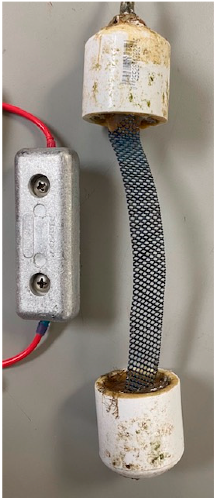
2.3. Arrangement of Cathodic Protection Systems

Sacrificial anode cathodic protection was provided by electrically connecting 3 × 1 × 0.25 in aluminum-zinc-indium anodes (Figure 2) to a busbar that shared connections with the steel coupons and steel pipe. Small drill holes in the top cap of each pipe permitted marine-grade wire attached to internal components to exit the pipe. Two sacrificial anodes were wired in series and placed inside Pipes 1 and 3 to provide internal CP. One anode was used to provide external CP to Pipe 1. The amount of sacrificial material needed to protect the pipes was verified using the equations for cathodic protection of offshore wind monopiles in DNV-RP-B401. Additionally, the status of the sacrificial anodes was checked weekly.
Impressed current cathodic protection anodes were made of a mixed-metal oxide mesh that was 7/8 in wide and 6 in long (Figure 2). One ICCP anode was used to provide protection to the inside of Pipes 2 and 4 and the external surface of Pipe 2. The ICCP systems were driven by an Electrosynthesis, Model 440, multichannel potentiostat, which was set to drive protection to −1000 mVAg/AgCl.

2.4. Data Collection

A Campbell Scientific datalogger (CSD), Cr6 model, recorded the potential of each pipe by comparing the voltage of each pipe’s busbar with reference to a silver/silver chloride reference electrode at 30 s intervals. The CSD also measured cathodic protection current demand by recording the potential drop across a 1-ohm shunt placed in series with the anodes.
The water chemistry inside of the pipes was measured on a weekly basis. Dissolved oxygen (DO), salinity, and temperature were measured with a dissolved oxygen sensor. pH levels were taken using a Vernier pH sensor, and pool test strips were used to identify the presence of chlorine in the water generated by ICCP systems. During weekly measurements, the ICCP systems were turned off. This reflected the safety precautions that would be used in a commercial setting.
At the end of the deployment, the pipes were removed from the water and visually assessed. Marine growth that had become established on the external surfaces of the pipes was quantified following the methods given in ASTM D6990-05 [26]. The pipes were then pressure washed to remove the marine growth and observe the condition of the steel and coating. The steel coupons inside of the pipes were removed and evaluated under a JEOL JSM-6380LV Scanning Electron Microscope (JEOL, Tokyo, Japan) to observe the surfaces and perform elemental analysis of the corrosion products.

3. Results

3.1. Internal Cathodic Protection Potentials

Steel in a seawater environment is considered polarized, or protected against corrosion, when its reference potential becomes more negative than −800 mV reference silver/silver chloride. However, potentials more negative than −900 mVAg/AgCl are recommended to ensure the development of cathodic chalks [1]. The ICCP systems were set to −1000 mVAg/AgCl, and the potentials of the SACP pipes naturally polarized after connecting to the sacrificial aluminum anodes.

3.1.1. Sealed Pipes

The internal potential of Pipe 1 (SACP) quickly polarized and never became more positive than −970 mV following the first 24 h in the water. The internal potential of Pipe 2 (ICCP), however, was extremely erratic, spiking to values more positive than −800 mV ten times over the eight weeks. These spikes were generally limited to four-hour spans, and seven of the spikes can be correlated to the times that the ICCP potentiostat was turned off during weekly data gathering. While both pipes experienced diurnal potential fluctuations, the potential variation inside Pipe 2 was much greater (Figure 3).

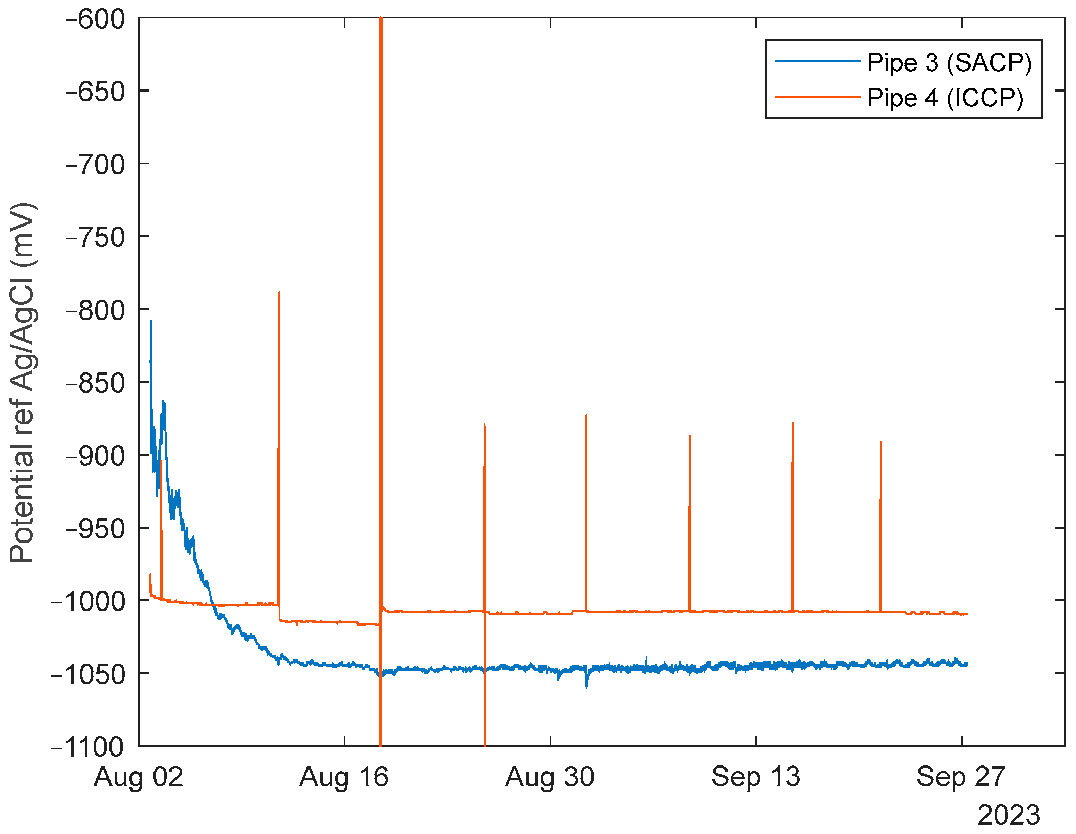
3.1.2. Perforated Pipes

The potentials of both perforated pipes consistently remained more negative than −900 mV. Additionally, the SACP system in Pipe 3 reached a lower resting potential (−1040 mV) than the sealed system in Pipe 1 (−1010 mV). Compared to the sealed pipes, the perforated pipes’ potentials fluctuated less. When the ICCP potentiostat was turned off during weekly data gathering, the potential of Pipe 4 still tended to remain more negative than −800 mV (Figure 4).

3.2. Internal Cathodic Protection Current Demand

The current demand (CD) is a measure of the energy that is required to maintain the steel at the desired reference potential and may be used to assess the corrosivity of the environment in which the steel is operating. According to Table A-1 in [1], bare steel in a tropical environment is assumed to experience an average initial CD of 150 mA/m2 and an average mean CD of 80 mA/m2. The initial CD is higher because the steel lacks any form of chalking layer or marine growth when it is first placed in the water. As coverage develops, less oxygen contacts the metal, and less current is required for protection. The recorded current demand for the six CP systems employed in this experiment are graphed in Figure 5.

3.2.1. Sealed Pipes

In theory, the sealed pipes should require a lower initial current demand as water movement and oxygen will be limited. The average CD of the sealed SACP system inside Pipe 1 after one day was 118 mA/m2. This was the lowest initial demand for all CP systems in the experiment. The CD continuously increased before peaking at 175 mA/m2 after seven days. For the remainder of the deployment, CD decreased, and when the pipes were removed, the demand dropped to 90–100 mA/m2.
The ICCP system protecting the sealed interior of Pipe 2 consistently output 600–650 mA/m2 for the first 36 days of the experiment. It is possible that this current output could have been higher without the upper bound of the potentiostat which limited CD inside Pipe 2 to 652 mA/m2. For the last two weeks of the deployment, the CD consistently dropped below 600 mA/m2 and was down to about 500 mA/m2 before being removed.

3.2.2. Perforated Pipes
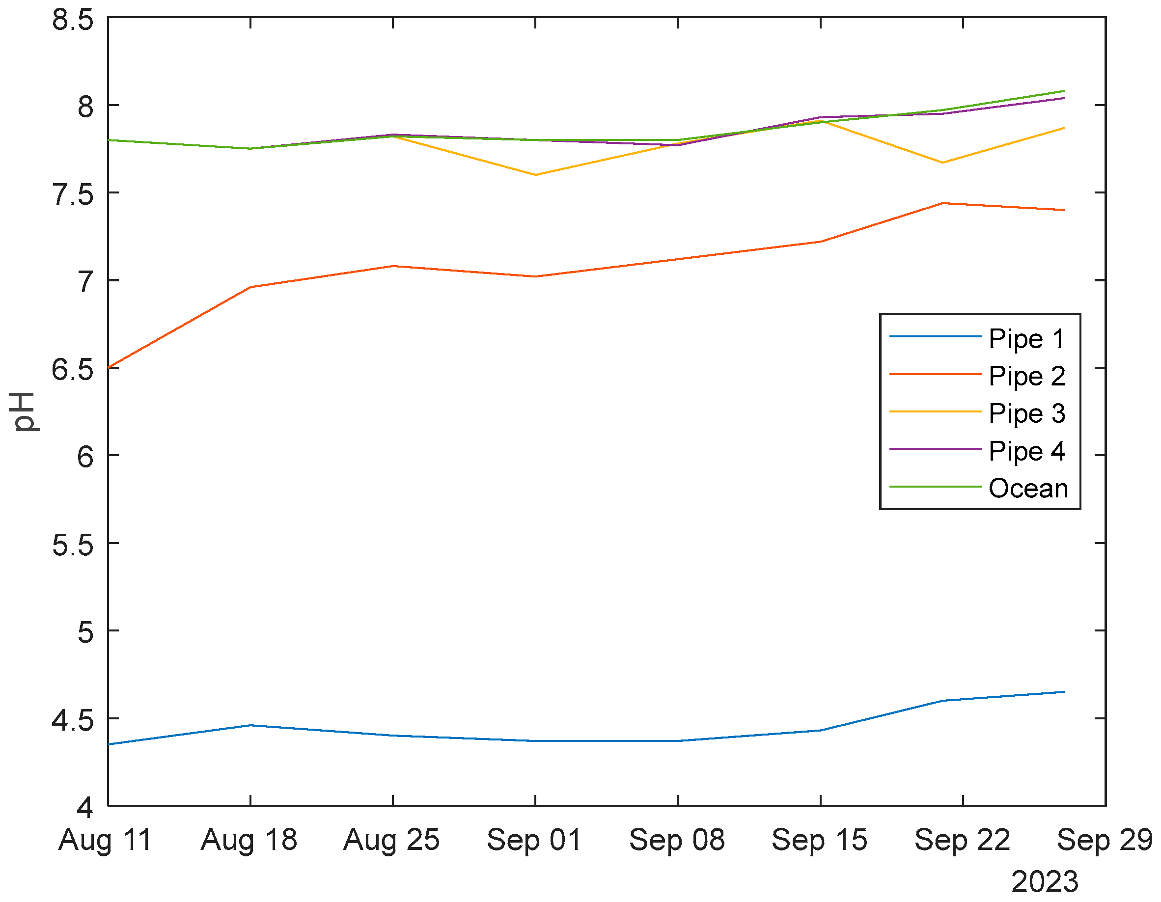
The CDs for the CP systems inside of perforated pipes 3 and 4 were lower than their sealed counterparts. Additionally, both CP systems reached lower CDs more quickly than the external systems applied to Pipes 1 and 2. At the end of the deployment, the SACP system inside Pipe 3 averaged 57–62 mA/m2, and the ICCP system inside Pipe 4 averaged 30–35 mA/m2. These demands were similar to the final external demands experienced by the SACP and ICCP systems, respectively.

3.3. pH Readings

The internal water in the sealed pipes became acidic immediately following the activation of their CP systems. The pH drop in Pipe 1 was the most extreme. At around the same time that the Pipe 1 internal CD peaked, a pH of 4.35 was recorded. This was the most acidic value recorded inside Pipe 1 throughout the entire deployment. Pipe 1’s pH values did not follow a consistent pattern during the weekly measurements, but the least acidic measurement of 4.65 was taken on the day that the pipes were removed. Similarly to Pipe 1, the most acidic pH measured in Pipe 2 (6.5) was taken after the first week of the deployment. By the third week, the pH had risen above 7, and the final value taken before removal was 7.4.
The pH levels inside the two perforated pipes both remained close to the pH of the ambient ocean water (Figure 6). Pipe 3 did have a slightly lower average pH of 7.78 compared to Pipe 4’s average of 7.86.

3.4. Corrosion Products and Elemental Analysis

3.4.1. Sealed Pipes

At the end of the deployment, the pipes were removed from the water, and the inside surfaces were inspected for corrosion products (Figure 7). A steel coupon from the top and bottom coupon sets of each pipe was examined under a scanning electron microscope to obtain the elemental composition of the corrosion products (Table 2). The greatest amount of cathodic reactant chalking layer was found inside Pipe 1 (sealed, Al SACP). It measured 0.25–0.39 mm thick, and SEM analysis determined that the layer was aluminum-based and likely composed of aluminum hydroxide, which is formed in the reaction between aluminum ions and water (see (4)). Fragments were found in the bottom cap sediment which had the distinct smell of sulfur. Sulfur was also identified as over 3% of the elemental weight of the chalking layer on the bottom steel coupon. DO measurements taken in the final month of the deployment showed that Pipe 1 had the lowest oxygen levels of the four pipes.
The coupons and internal surface of Pipe 2 (sealed ICCP) were covered in brown and bright orange rust products. A chalk layer, identified to be calcium-based, was only present on a small portion of the bottom coupon set which was analyzed separately on the SEM. Exposed iron was present in this region at 10% by weight, but elsewhere on Pipe 2 coupons, iron made up approximately 57% of the elemental analysis, reflecting the lack of cathodic chalk. During each weekly measurement, free chlorine was measured as being present in the water of Pipe 2. Free chlorine was not detected inside the other three pipes. For the last three weekly measurements, the DO levels in Pipe 2 were measured higher than the other pipes and the ocean. However, the DO sensor may have been biased by the internal elevated chlorine level. When the pipes were taken out of the water, Pipe 2’s bottom rubber cap was lost, so a visual assessment of Pipe 2’s sediment was not able to be taken.

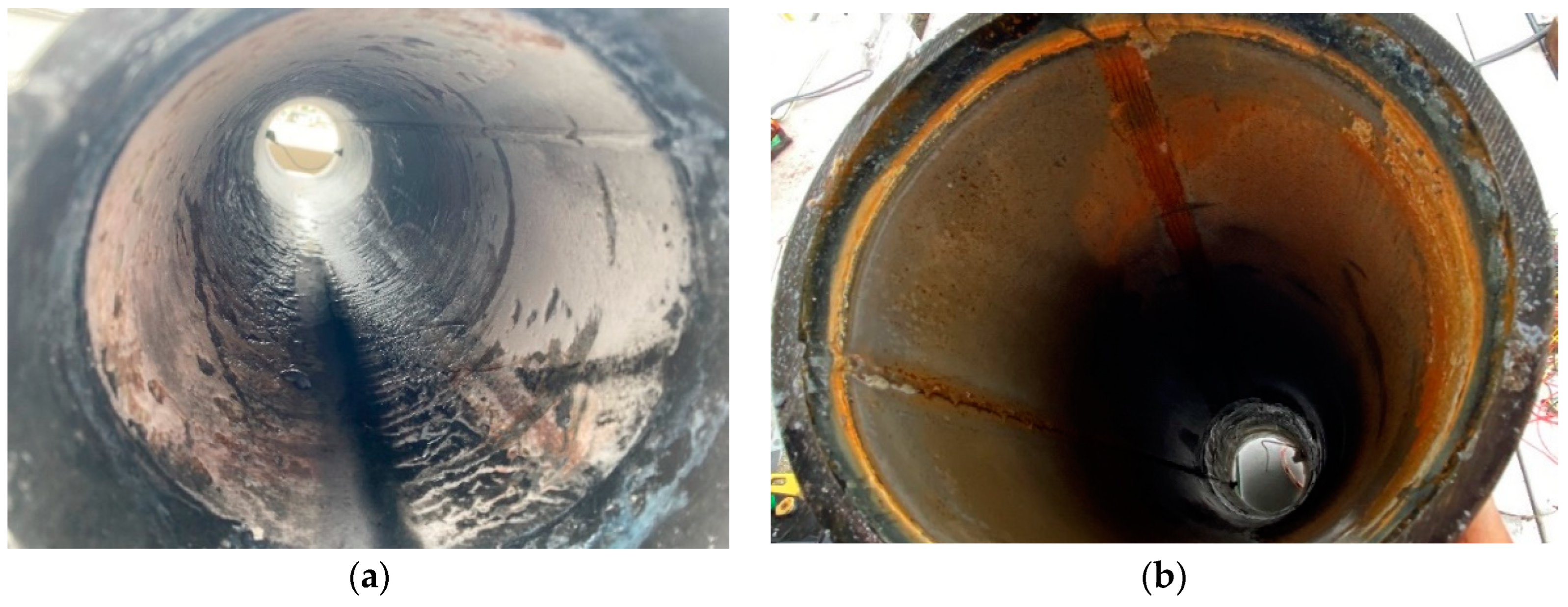
3.4.2. Perforated Pipes

Some white chalk layers were present in both Pipes 3 and 4, although it was not a consistent or thick layer. Elemental analysis of the coupons revealed that calcium was the dominant element, found on an average of 12.9% by weight on Pipe 3 and 17.9% on Pipe 4. Exposed iron was detected by the SEM at an average of 8.4% on Pipe 3 and 6.7% on Pipe 4. In addition to chalk, some rust was also present inside the perforated pipes. However, the majority of this rust was present prior to the pipes’ deployment in seawater.
The DO levels inside Pipes 3 and 4 were consistently lower than DO in the ambient seawater. The DO levels in Pipe 4 were less than in Pipe 3, but the scent of sulfur was much stronger in the Pipe 3 sediment when the pipes were removed. The sulfur concentration measured on the coupons was low, however, and only found on a top coupon in both pipes in concentrations of less than 0.6%.

3.5. Marine Organism Recruitment

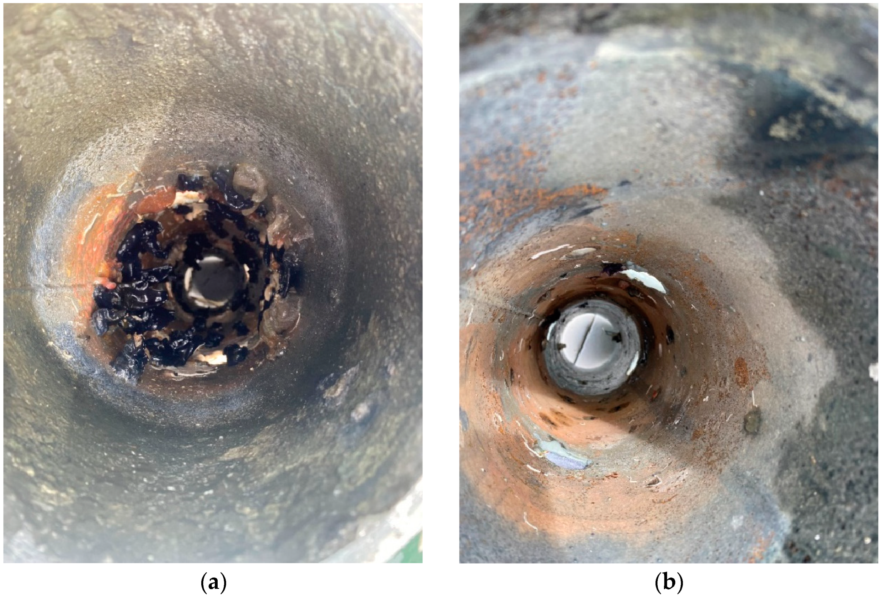
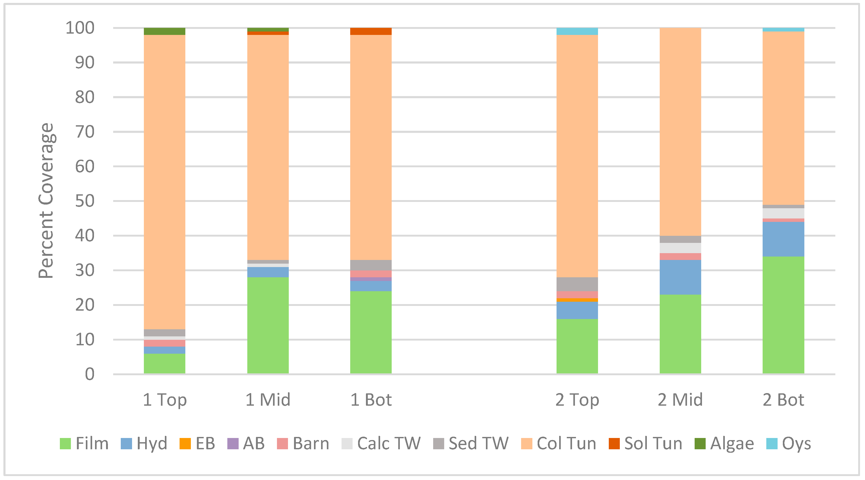
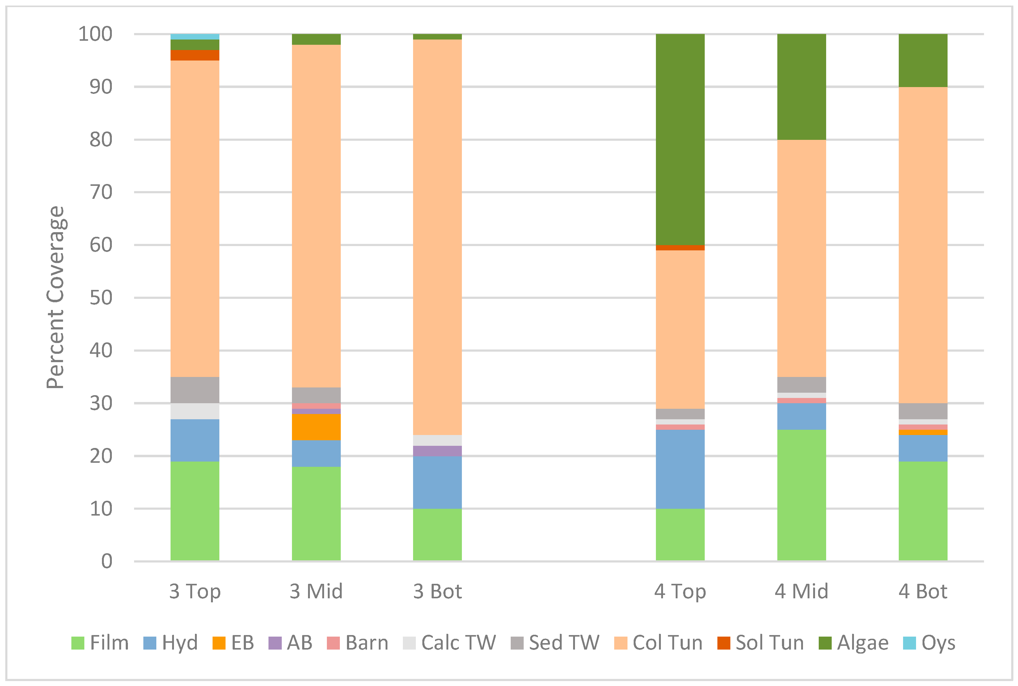
3.5.1. Internal Recruitment to Perforated Pipes

Marine organisms were recruited to the internal surfaces of Pipes 3 and 4 after entering through the perforations. The species found inside the two pipes were similar, implying that the difference in cathodic protection systems did not affect marine organism recruitment. Large, black, solitary tunicates were the most prominent species found, but colonial tunicates, tubeworms, and sponges were also present. The growth in both pipes was concentrated at the elevations of the perforations. After the insides of both pipes were pressure washed, less rust was found underneath the areas where dense growth had been present (Figure 8).

3.5.2. External Recruitment

Recruitment of marine organisms to the external surfaces was assessed using ASTM D6990-05, and this enabled a comparison between the coated and uncoated surfaces and the different cathodic protection methods (Al SACP, ICCP, and fully coated).
External recruitment to all four pipes was similar (Figure 9). Colonial tunicates were the most common organism present on all four pipes. Other macro-organisms were found in concentrations of less than 10%. Pipe 4 did experience some algal growth, but this can be attributed to the pipe’s location at the test site with a higher level of sunlight exposure.

4. Discussion

4.1. Internal Cathodic Protection and Water Chemistry

The application of both SACP and ICCP to the sealed pipes altered the seawater chemistry within the pipes. This prevented the formation of cathodic chalks on the interior steel surface and also increased the current demand required to polarize the steel to the protection potential. The reduction in pH inside Pipe 1 was similar to that recorded by [20], and it led to the formation of an aluminum hydroxide deposit on the steel surface. Despite the pH being reduced to under five, the inside of Pipe 1 never depolarized, and the potential remained more negative than −1000 mVAg/AgCl for the last six weeks of the deployment. It is possible that a longer deployment would have further altered the seawater chemistry in Pipe 1, causing it to depolarize, as observed by [20]. Their CP current demand only exceeded 200 mA/m2 several months after internal Al SACP installation.
Acidic conditions inside Pipe 2 (ICCP) prevented the formation of a chalking layer and the chlorine generated by the anode created a corrosive environment. Corrosion products observed inside Pipe 2 suggest that chlorine generated by the ICCP is more of a serious threat to steel corrosion than acidity. Pipe 2 remained at a significantly higher pH than Pipe 1, but it required a much higher current demand and still experienced internal rusting.
The CP systems inside perforated pipes operated in a similar manner to the CP applied to the external steel surfaces. They required a lower current demand and did not develop the reduced pH levels generated in both sealed pipes. This demonstrates that perforated monopile designs would enable internal cathodic protection to provide effective corrosion control.

4.2. Internal Recruitment of Marine Organisms to the Perforated Pipes

The recruitment of marine organisms to the internal surfaces of the perforated pipes was similar for both the SACP and ICCP systems. The species inside of Pipes 3 and 4 appeared to be healthy, which implies that cathodically protected steel provides a stable surface for organisms to attach. This is indicative of a solid foundation for the development of a more complex marine ecosystem within and around the structures. Ideally, future research could investigate how ecosystems develop amongst internal cathodic protection systems on longer time scales, and whether there are long-term effects on wildlife or the CP.
A difference was observed between external and internal species coverage. Solitary tunicates were more dominant internally. Furthermore, despite both experiments taking place at the same location and the same time of year, the internal recruitment in this deployment was significantly less dense than Maher’s 2018 experiment with freely corroding and Zn SACP perforated pipes. Maher’s experiment, where arborescent bryozoan covered much of the pipes’ interior surfaces, saw nearly 100% of the internal surfaces covered by marine organisms beginning at the depth of the first set of perforations. Maher’s pipes also had a large community of mobile organisms living inside and around them that were not found during the removal process of this deployment. The differences in the recruitment of marine organisms between this and Maher’s deployment may have been due to the inherent variability in the availability of the larval stages of marine invertebrates. Repetition of this experiment in multiple ocean environments would help to remove some of this biological randomness.
The pipes in the Maher experiment also contained two extra perforations on a similar length of pipe compared to this deployment. More perforations may be beneficial to the development of an ecosystem inside monopiles because they allow more seawater flushing and organisms to enter the interior. Future research is required, however, to understand the requirements for the size and placement of such perforations to ensure optimum water exchange while avoiding possible occlusion due to marine growth which could negate internal corrosion benefits. The perforation design and corresponding flush rate utilized by the steel pipes in this experiment are not necessarily proportional to designs applicable to offshore wind monopiles, which must additionally consider factors such as wave loading and fatigue life. This may limit the practicable amount of water flushing offshore monopiles are able to achieve.

4.3. Other Considerations of Perforation Design

While the present design life for offshore wind turbines is between 20 and 30 years, foundations are often designed for longer [27]. The choice of design and the method for the management of corrosion and biofouling of the monopile foundations will influence the design life and their impact on the local ecology [28]. While the incorporation of perforation design is likely to increase the capital expenditure of OWFs, there are possible operational savings due to the reliability of perforated internal corrosion management. Additionally, the benefits of creating surfaces that become habitats for marine organisms are an increase in biological productivity and a contribution to the local ecology. This increases the value of monopile foundations and allows them to continue to beneficially contribute to sustainability goals even following the decommission of an OWF.

5. Conclusions

This and prior research [4] have clearly demonstrated the advantages of incorporating perforations in steel pipes and monopiles as a method to enable the application of cathodic protection for corrosion control of internal surfaces and the potential to create habitats for marine life. Furthermore, other research suggests that perforations may have the advantage of reducing wave loading at the surface [21] and scour at the sea floor [22]. There are many unanswered questions regarding the structural and hydrodynamic characteristics of perforated structures that require further investigation to understand if such designs can provide long-term foundation support for offshore wind turbines. A cost analysis may then be performed that includes CAPEX, OPEX, and potential environmental benefits that will contribute to improved ecosystems and sustainability.

Author Contributions

Conceptualization, A.P., G.S., D.K., and C.M.H.; methodology, A.P. and G.S.; software, A.P.; validation, A.P. and G.S.; formal analysis, A.P; investigation, A.P. and G.S.; resources, G.S., D.K., and C.M.H.; writing—original draft preparation, A.P. and J.D.; writing—review and editing, A.P., G.S., and J.D.; visualization, A.P. and J.D.; supervision, G.S. and D.K.; project administration, A.P., G.S., and D.K.; funding acquisition, G.S. and D.K. All authors have read and agreed to the published version of the manuscript.

Funding

This study was funded by the Bureau of Ocean Energy Management (BOEM), U.S. Department of the Interior, Washington, D.C., under Contract 140M0121P0013 and the Office of Naval Research through grant N00014-23-1-2452.

Institutional Review Board Statement

Not applicable.

Informed Consent Statement

Not applicable.

Data Availability Statement

Additional data pertaining to this experiment can be found at https://repository.fit.edu/etd/1403/. Accessed on 2 June 2024.

Acknowledgments

The authors would like to acknowledge the support from the Bureau of Ocean and Energy Management through a project that examined the influence of corrosion protection system design, including the use of perforations on the performance of monopiles. They would also like to thank the Office of Naval Research for allowing the experiments to be run at the static immersion test site at Port Canaveral, FL.

Conflicts of Interest

The authors declare no conflicts of interest.

References

  1. DNVGL-RP-B401; Cathodic Protection Design Recommended Practice. DNVGL: Bærum, Norway, 2017.
  2. Erdogan, C.; Swain, G. Conceptual sacrificial anode cathodic protection design for offshore wind monopiles. Ocn. Eng. 2021, 235, 109339. [Google Scholar] [CrossRef]
  3. Swain, G. A Guide to Developing a Biofouling Management Plan. Mar. Tech. Soc. J. 2017, 51, 105–110. [Google Scholar] [CrossRef]
  4. Maher, M. The Corrosion and Biofouling Characteristics of Sealed vs. Perforated Offshore Monopile Interiors: Experiment Design Comparing Corrosion and Environment Inside Steel Pipe. Master’s Thesis, Florida Institute of Technology, Melbourne, FL, USA, December 2018. [Google Scholar]
  5. Wassick, A.; Hunsucker, K.Z.; Swain, G. Measuring the recruitment and growth of biofouling communities using clear recruitment panels. Biofouling 2023, 39, 643–660. [Google Scholar] [CrossRef] [PubMed]
  6. U.S. Department of Energy. Offshore Wind Market Report, 2023rd ed.; U.S. Department of Energy: Washington, DC, USA, 2023. [Google Scholar]
  7. Haselibozchaloee, D.; Correia, J.; Mendes, P.; de Jesus, A.; Berto, F. A review of fatigue damage assessment in offshore wind turbine structure. Int. J. Fatigue 2022, 164, 107145. [Google Scholar] [CrossRef]
  8. Price, S.J.; Figueira, R.B. Corrosion Protection Systems and Fatigue Corrosion in Offshore Wind Structures: Current Status and Future Perspectives. Coatings 2017, 7, 25. [Google Scholar] [CrossRef]
  9. Chaves, I.A.; Peterson, R.; Melchers, R.E.; Jeffrey, R. Corrosion of the interior steel surfaces of offshore monopiles. Ships Offshore Struct. 2024, 19, 125–133. [Google Scholar] [CrossRef]
  10. Black, A.R.; Mathiesen, T.; Hilbert, L.R. Corrosion Protection of Offshore Wind Foundations. In Proceedings of the CORROSION 2015, Dallas, TX, USA, 15–19 March 2015. [Google Scholar]
  11. Lomholt, T.N.; Mathiesen, T.; Egelund, S.; Bangsgaard, D.B. Unification of Corrosion Protection for Offshore Wind Farms—Collaboration in Partnerships. In Proceedings of the CORROSION 2018, Pheonix, AZ, USA, 15–19 April 2018. [Google Scholar]
  12. Cherif, O. Impressed Current System for Internal Corrosion Protection in Monopiles for Offshore Windmills. Master’s Thesis, Norwegian University of Science and Technology, Trondheim, NO, USA, 2022. [Google Scholar]
  13. Hilbert, L.R.; Black, A.R.; Andersen, F.; Mathiesen, T. Inspection and monitoring of corrosion inside monopile foundations for offshore wind turbines. In Proceedings of the EUROCORR 2011, Stockholm, Sweden, 4–8 September 2011. [Google Scholar]
  14. Krebs, D.I.T. ICCP System for Internal Protection of Monopiles for Offshore Wind Farms. In Proceedings of the CORROSION 2018, Phoenix, AZ, USA, 15–19 April 2018. [Google Scholar]
  15. Sunday, K.; Brennan, F. A review of offshore wind monopiles structural design achievements and challenges. Ocn. Eng. 2021, 235, 109409. [Google Scholar] [CrossRef]
  16. Jensen, K.S.; Petersen, S.J.; Pedersen, R.R. European offshore wind engineering—Past, present and future. Proc. Inst. Civ. Eng. 2018, 171, 159–165. [Google Scholar] [CrossRef]
  17. VGBE-S-021-01-2023-05-EN; Corrosion Protection for Offshore Wind Structures. 4th ed. vgbe energy e.V.: Essen, Germany, 2023.
  18. Kirchgeorg, T.; Weinberg, I.; Hornig, M.; Baier, R.; Schmid, M.J.; Brockmeyer, B. Emissions from corrosion protection systems of offshore wind farms: Evaluation of the potential impact on the marine environment. Mar. Poll. Bull. 2018, 136, 257–268. [Google Scholar] [CrossRef]
  19. Veronelli, L.A. Empirical and Computer Aided Design of Cathodic Protection Systems. Master’s Thesis, Pelitecnico di Milano, Milan, Italy, 5 October 2012. [Google Scholar]
  20. Delwiche, A.; Tavares, I. Retrofit Strategy using Aluminum Anodes for the Internal Section of Windturbine Monopiles. In Proceedings of the CORROSION 2017, New Orleans, LA, USA, 26–30 March 2017. [Google Scholar]
  21. Andersen, J.; Abrahamsen, R.; Andersen, T.L.; Andersen, M.T.; Baun, T.L.; Neubauer, J.L. Wave Load Mitigation by Perforation of Monopiles. J. Mar. Sci. Eng. 2020, 8, 352. [Google Scholar] [CrossRef]
  22. Elnikhely, E.A. Minimizing scour around bridge pile using holes. Ain Shams Eng. J. 2017, 8, 499–506. [Google Scholar] [CrossRef]
  23. Heaf, N.J. The Effect of Marine Growth on the Performance of Fixed Offshore Platforms in the North Sea. In Proceedings of the Offshore Technology Conference, Houston, TX, USA, 30 April 1979. [Google Scholar] [CrossRef]
  24. Degraer, S.; Carey, D.A.; Coolen, J.W.P.; Hutchison, Z.L.; Kerckhof, F.; Rumes, B.; Vanaverbeke, J. Offshore Wind Farm Artificial Reefs Affect Ecosystem Structure and Functioning. Oceanography 2020, 33, 48–57. [Google Scholar] [CrossRef]
  25. Hutchison, Z.L.; Bartley, M.L.; Degraer, S.; English, P.; Khan, A.; Livermore, J.; Rumes, B.; King, J.W. Offshore Wind Energy and Benthic Habitat Changes. Oceanography 2020, 33, 58–69. [Google Scholar] [CrossRef]
  26. American Society for Testing and Materials D6990-20; Standard Practice for Evaluating Biofouling Resistance and Physical Performance of Marine Coating Systems. ASTM International: West Conshohocken, PA, USA, 2020.
  27. Arany, L.; Bhattacharya, S.; Macdonald, J.; Hogan, S.J. Design of monopiles for offshore wind turbines in 10 steps. Soil Dyn. Earthq. Eng. 2017, 92, 126–152. [Google Scholar] [CrossRef]
  28. Erdogan, C.; Swain, G. The Effects of Biofouling and Corrosion Products on Impressed Current Cathodic Protection System Design for Offshore Monopile Foundations. J. Mar. Sci. Eng. 2022, 10, 1670. [Google Scholar] [CrossRef]
Figure 1. Representation of a sealed pipe protected with Al SACP (not to scale).
Jmse 12 01299 g001
Figure 2. Sacrificial aluminum and mixed-metal oxide anodes.
Jmse 12 01299 g002
Figure 3. Internal potentials (ref Ag/AgCl) of the sealed steel pipes protected by SACP and ICCP systems.
Jmse 12 01299 g003
Figure 4. Internal potentials (ref Ag/AgCl) of the perforated steel pipes protected by SACP and ICCP systems.
Jmse 12 01299 g004
Figure 5. Internal current demands of the four internal and two external cathodic protection systems.
Jmse 12 01299 g005
Figure 6. pH measurements taken weekly inside of the four pipes.
Jmse 12 01299 g006
Figure 7. (a) The interior of Pipe 1 (sealed, SACP) after 8-week deployment; (b) The interior of Pipe 2 (sealed, ICCP) after 8-week deployment.
Jmse 12 01299 g007
Figure 8. (a) Interior of Pipe 3 (Al SACP) after 8-week deployment; (b) Pipe 3 after power washing; (c) Interior of Pipe 4 (ICCP) after 8-week deployment; (d) Pipe 4 after power washing.
Jmse 12 01299 g008aJmse 12 01299 g008b
Figure 9. The distribution of marine organism recruitment to the external surfaces of cathodically protected uncoated (Pipes 1 and 2) and coated (Pipes 3 and 4) steel.
Jmse 12 01299 g009aJmse 12 01299 g009b
Table 1. Cape Marina deployment details matrix.
Internal CoatingExternal Coating
PipeProtectionSplash 1ImmersedSplash 1Immersed
Sealed1Al SACPx x
2ICCPx x
Perforated3Al SACPx xx
4ICCPx xx
1 The splash zone constituted the top 20.25 in of the pipes.
Table 2. Percent weight of elements identified on steel coupons from SEM analysis.
1B
Coupon
1B
Loose Chalking
1T
Coupon
1T
Loose Chalking
2B Chalking Layer2B Non-Chalking Area2T3B3T4B4T
O51.3364.2744.4963.7452.628.4735.7350.5657.2154.0349.26
Fe10.080.8126.080.699.9858.2856.9710.845.995.228.2
Ca00.240021.656.231.79.316.5213.8122
Al11.4122.396.9620.161.880.1505.515.364.11.46
Mg8.343.4512.963.142.710.840.936.675.444.811.36
Si0.25000.455.810.530.834.957.0212.436.12
Mo6.8803.128.040003.68000
Nb01.63003.063.33.68003.33.05
Zn5.872.52.510.790000000
Na00000004.3200.565.46
Cl00.8700.91.050.510.163.70.0401.12
Br5.8400.9900000000
S03.840000000.5500.45
Co00000.261.2300.280.090.190.3
K00000.4000.20.210.510.47
T—sample from top steel coupon set. B—sample from bottom steel coupon set.
Disclaimer/Publisher’s Note: The statements, opinions and data contained in all publications are solely those of the individual author(s) and contributor(s) and not of MDPI and/or the editor(s). MDPI and/or the editor(s) disclaim responsibility for any injury to people or property resulting from any ideas, methods, instructions or products referred to in the content.

