Article

Enhanced Performance of a Hydrokinetic Turbine through a Biomimetic Design

by
María Isabel Lamas Galdo
1,*,
Juan de Dios Rodríguez García
1,
Antonio Couce Casanova
1,
Javier Blanco Damota
1,
Claudio Giovanni Caccia
2,
José Manuel Rebollido Lorenzo
3 and
Javier Telmo Miranda
4
1
Escuela Politécnica de Ingeniería de Ferrol, Campus Industrial de Ferrol, Universidade da Coruña, 15403 Ferrol, Spain
2
Department of Aerospace Engineering, Politecnico di Milano, 20156 Milan, Italy
3
IES de Valga, 36645 Xanza, Spain
4
Escuela Técnica Superior de Ingenieros Industriales, Universidad Nacional de Educación a Distancia (UNED), 28040 Madrid, Spain
*
Author to whom correspondence should be addressed.
J. Mar. Sci. Eng. 2024, 12(8), 1312; https://doi.org/10.3390/jmse12081312
Submission received: 19 June 2024 / Revised: 26 July 2024 / Accepted: 1 August 2024 / Published: 2 August 2024
(This article belongs to the Section Ocean Engineering)

Abstract

:
Hydrokinetic energy constitutes a source of renewable energy. However, many regions have flow velocities that are too low for effective energy extraction, and conventional turbines are not suitable for these sites. In order to address this challenge, the present work proposes a novel vertical axis hydrokinetic turbine designed for environments where conventional turbines are not feasible due to a low water velocity. The turbine’s design is inspired by biological principles, enhancing the traditional Savonius turbine by incorporating a Fibonacci spiral-inspired blade configuration. The turbine’s performance was subjected to a rigorous analysis through Computational Fluid Dynamics (CFD). The results demonstrate a notable improvement, with a 15.1% increase in the power coefficient compared to the traditional Savonius turbine. This innovative approach not only extends the applicability of hydrokinetic turbines to low-flow regions but also underscores the potential of biomimicry in optimizing renewable energy technologies. The findings of this study indicate that integrating natural design principles can result in more efficient and sustainable energy solutions, thereby paving the way for the broader adoption of hydrokinetic power in diverse geographical settings.

1. Introduction

Renewable energy is increasingly seen as a solution to meet the growing global energy demand while mitigating environmental impacts. Among the various renewable energy sources, there is growing interest in the potential of hydrokinetic energy to provide sustainable power generation. In locations with suitable conditions, hydrokinetic energy offers significant potential for the generation of power [1,2]. The development of marine renewable energy technologies, including hydrokinetic energy conversion systems, has been the focus of extensive research and technological advancement. Unfortunately, many regions of the world do not present appropriate conditions for the deployment of renewable energy technologies [3]. A study by Behrouzi et al. [4] reviewed the global potential of renewable energy technologies, including hydrokinetic turbines, highlighting the unique characteristics of hydrokinetic turbines and their potential for energy generation in various regions of the world. In a further study, Brasil et al. [5] examined the specific design considerations required to optimize the performance of hydrokinetic turbines in different regional contexts. Vaz et al. [6] conducted an evaluation of the potential of hydrokinetic turbines downstream of dams in different geographical locations.
One of the primary issues identified by the aforementioned authors is the flow velocity. According to this, the use of hydrokinetic turbines for energy generation in low-flow-velocity environments has garnered considerable attention in recent years. In the context of small-scale power generation, vertical-axis turbines are often preferred over horizontal-axis turbines due to several advantages, including their simpler design and independence from flow direction [7]. Within the category of vertical-axis hydrokinetic turbines, the most commonly used types include the Squirrel cage Darrieus, H-Darrieus, Gorlov, and Savonius [7]. In this context, the Savonius turbine has demonstrated its suitability for harnessing energy from low-flow-velocity applications, offering an interesting advantage regarding the low starting torque requirements. Kumar and Saini [8] suggested that the Savonius hydrokinetic turbine is suitable for flow velocities of 0.5 m/s and above. Singh and Kumar [9] calculated the optimal water velocity for the Savonius turbine to be 0.65 m/s. Susilo et al. [10] emphasized the advantage of the Savonius water turbine for relatively low-velocity water flows, highlighting its applicability in such conditions. Katayama et al. [11] indicated that the Savonius type is suitable for utilization in open channels with ultra-low-head hydropower sites, providing insights into its applicability in specific hydrokinetic environments.
While the Savonius turbine offers several advantages, it is important to highlight its low efficiency [12]. This is lower than that of other types of turbines and considerably below the Betz limit (59.3%). Extensive research has been conducted on the performance parameters and design optimization of Savonius hydrokinetic turbines. In this context, computational fluid dynamics (CFD) represents a powerful tool for simulating and understanding the complex flow phenomena associated with hydrokinetic turbines. It enables detailed investigations into their hydrodynamic characteristics and efficiency. In comparison to experimental setups, numerical models offer substantial benefits. Unlike the high costs and time required for conducting experimental tests on different configurations, CFD models serve as a rapid and cost-effective tool for analyzing the performance parameters of various geometries. Furthermore, numerical models offer valuable insights into fields that are often too complex to measure through experimental methods. Kumar and Saini [8] emphasized the significance of CFD in evaluating the performance parameters of Savonius hydrokinetic turbines, highlighting the need for further research in optimizing their design. Patel et al. [13] and Barbarić and Guzović [14] employed CFD to examine the impact of the aspect ratio, overlap ratio, and diffuser geometrical configurations on the performance of hydrokinetic turbines, thereby providing valuable insights into potential design improvements. Mejia et al. [15] underscored the importance of CFD simulations in the assessment of vertical-axis hydrokinetic turbines, demonstrating the potential for integrating numerical and analytical methods to evaluate turbine designs. Fertahi et al. [16] employed CFD to analyze a combined Savonius–Darrieus hydrokinetic turbine. Taludkar et al. [17] conducted 2D CFD analyses and experimental studies in an open channel at a water velocity of 0.8 m/s. Tian et al. [18] investigated a novel blade design to enhance the performance of the Savonius hydrokinetic turbine using CFD. Kumar and Saini [19] conducted a numerical analysis of the effect of the blade arc angle and blade shape for flow velocities from 0.5 to 2 m/s. Sarma et al. [20] compared a Savonius hydrokinetic turbine with a Savonius wind turbine using CFD for water current velocities ranging from 0.3 to 0.9 m/s. Other authors [21,22,23] employed CFD to investigate the impact of deflectors in Savonius hydrokinetic turbines.
The present study introduces a novel design of the Savonius turbine. This design is inspired by the Fibonacci spiral, which is found in various aspects of nature. The blade profile based on the Fibonacci spiral has been previously analyzed by the authors for wind turbines [24,25,26,27,28], resulting in significant improvements compared to the conventional Savonius wind turbine. The objective of the present study is to extend the analysis of the Fibonacci profile to the case of hydrokinetic turbines. The performance of this design was evaluated using Computational Fluid Dynamics (CFD), offering insights into the fluid flow problem and assessing the turbine’s behavior. This analysis enables the evaluation of the impact of the Fibonacci spiral-inspired blade design, thereby providing valuable guidance for optimizing its efficiency and effectiveness in harnessing hydrokinetic energy. This novel application underscores the potential of biomimicry in optimizing renewable energy technologies, demonstrating its promise in advancing the field of hydrokinetic energy as well.

2. Materials and Methods

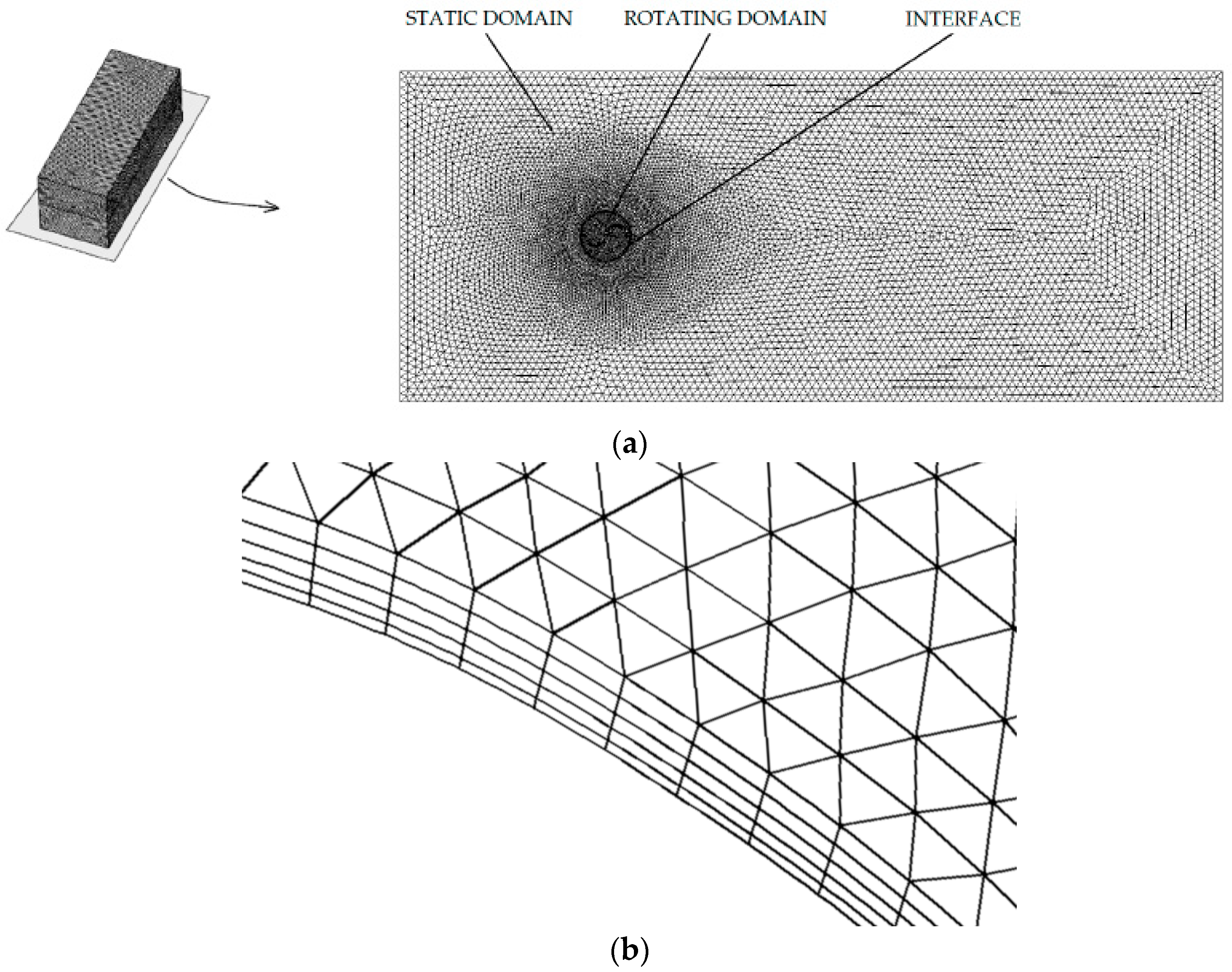
2.1. Numerical Model

The Savonius turbine, illustrated in Figure 1a, is a type of vertical axis turbine characterized by its simple and robust design. It comprises curved blades arranged in a semicircular fashion around a central shaft. This distinctive configuration enables the Savonius turbine to effectively capture energy from fluid flows, including wind and water currents, regardless of the direction of the flow. The turbine operates based on the principle of drag, with the curved blades generating drag force differentials as they rotate, thereby converting the kinetic energy of the fluid flow into mechanical energy. The turbine’s inherent ability to self-start at a very low fluid velocity and its simplicity of construction contribute to its versatility and potential for decentralized energy generation in various settings, especially in environments with low-speed fluid currents.
As previously indicated, this study employs CFD to investigate a modification of the Savonius-type vertical axis turbine. This model was previously validated with experimental results. To this end, data from Blackwell et al. [27] were employed. For this purpose, an examination was conducted on a turbine 1 m in diameter with two blades. Other parameters, including the overlap, separation gap, and twist angle, were 0. The overlap, O in Figure 1b, represents the extent to which a blade extends over the other. The separation gap, SG in Figure 1b, is the distance separating the blades. The twist angle, in Figure 1c, measures the helicality along the height. The aspect ratio is the relation between the height and the diameter. The turbine configuration thus consists of two semicircular blades and two supporting endplates.
In regard to the numerical model, the open-source software OpenFOAM v2012 was selected for its accessibility, thereby facilitating comprehensive access to the code for the purposes of understanding and manipulation. The main computational setup parameters are summarized in Table 1. The governing equations employed were the Reynolds-averaged Navier–Stokes (RANS) equations, which incorporate the principles of mass and momentum conservation. In order to account for the effect of turbulence, the SST k-ω model was selected on the basis of its demonstrated effectiveness in previous studies [25,28]. In such investigations, several turbulence models were evaluated, and the SST k-ω model was identified as the most suitable for these types of simulations despite its higher computational cost compared to commonly used models like k-ε. With regard to the pressure–velocity coupling, the PIMPLE algorithm was employed, while a temporal treatment was conducted using an implicit method. The time step was set to a constant value equivalent to one degree of rotation, taking into account the rotational speed. This resulted in a range of timestep values, from 0.0009 s to 0.23 s, depending on the specific parameters of each simulation. In order to achieve a quasi-steady state, multiple revolutions were analyzed. The results presented in this study correspond to the sixth rotation.
The domain utilized in the present work is depicted in Figure 2, with dimensions of 23 × 8 × 8 m3, i.e., 23D × 8D × 8D. It was checked that these dimensions are sufficiently large to mitigate any border effects, as evidenced by the repetition of simulations using domains of 10 × 10 × 25 m3 and 12 × 12 × 30 m3, which yielded consistent results. The main boundary conditions considered in the present work are also outlined in the figure. The upstream face was modeled as a velocity inlet, while the downstream face was modeled as an outlet. External faces were designated as free slip surfaces to minimize border effects, imposing zero shear stress, meaning the tangential velocity derivative normal in relation to the boundary is zero. The turbine blades were treated as no-slip surfaces. The turbulence at the boundary conditions was modeled through wall functions. The OpenFOAM wall functions kqRWallFunction and omegaWallFunction were employed for the turbulence kinetic energy and the turbulence specific dissipation rate, respectively.
Figure 3 illustrates the mesh utilized in the study, providing both a three-dimensional view and a detailed depiction of the middle plane. The mesh comprises tetrahedral elements ranging from 0.05 to 0.2 m in size, with a finer resolution implemented around the turbine. Two distinct zones were defined: static and rotating. The rotating domain encompasses a cylinder surrounding the turbine, which rotates about the turbine axis, while the static domain encompasses the remaining stationary region. A sliding interface was established to connect the static and rotating domains, thereby facilitating the interaction between the two zones.
To ensure the robustness and reliability of the numerical simulations, multiple meshes with varying element sizes were examined to assess the independence of the results from the mesh size. This rigorous approach helps to validate the accuracy and consistency of the computational model, ensuring that the obtained results are not unduly influenced by the mesh resolution. By systematically testing different mesh configurations and confirming the convergence of results across these variations, confidence in the accuracy and robustness of the simulation outcomes is bolstered. Four meshes were tested, with the number of elements shown in Table 2. This table also shows the power coefficient obtained at TSR = 1. It can be observed that meshes 3 and 4 provide the same result. Based on this, mesh 3 was selected. This mesh has 4.5 × 10⁶ elements, of which 1.1 × 10⁶ correspond to the rotating domain and the rest corresponded to the static domain. The maximum skewness is 0.78. At the blade’s surface, a boundary layer with five layers was set, as illustrated in Figure 3b, providing a y+ < 1. It is crucial to note that a finer mesh downstream of the turbine would enhance the accuracy in capturing the wake dynamics and the power coefficient. Nevertheless, the outcomes yielded by the selected mesh were considered sufficiently accurate.
Figure 4 presents a comparison between the average power coefficients obtained from numerical simulations and experimental trials. The experimental data shown in this figure were obtained from an independent study [29], which was used to validate the numerical model. The power coefficient was plotted against the tip speed ratio, as indicated in Equations (1) and (2), respectively. In these equations, the following variables are defined: ω is the rotational velocity, R is the turbine radius, V is the free-stream flow velocity, P is the power, ρ is the density, S is the cross-sectional area determined by multiplying the radius by the height, and D is the turbine diameter.
TSR = blade   tip   tangential   velocity wind   speed = ω R V
C p = power available   power = P 0.5 ρ SV 3
Notably, a satisfactory agreement is observed between the two sets of data in Figure 4, with an average error of 5.8%. The average error was calculated using Equation (3), which compares the experimental and numerical values. Both datasets exhibit a similar trend, with an initial increase in average power coefficients followed by a decline beyond a certain tip speed ratio. This behavior can be attributed to the phenomenon whereby increasing tip speed ratios lead to higher rotational velocities, causing the blade tips to exceed the incoming air velocity. Consequently, less power is effectively transferred from the air to the turbine, resulting in a reduction in the net power output. In contrast, another peculiarity that can be observed in Figure 4 is that the experimental power coefficients are higher than the numerical ones. This discrepancy can be attributed to the blockage effect, which arises from using a wind tunnel with limited dimensions. This restriction causes the flow around the turbine to accelerate locally, increasing the wind velocity in the test section and subsequently raising the drag and the measured power coefficient.
error   ( % ) = 100 | C Pexperimental C Pnumerical | C pnumerical ¯

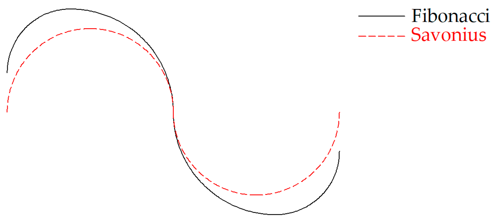
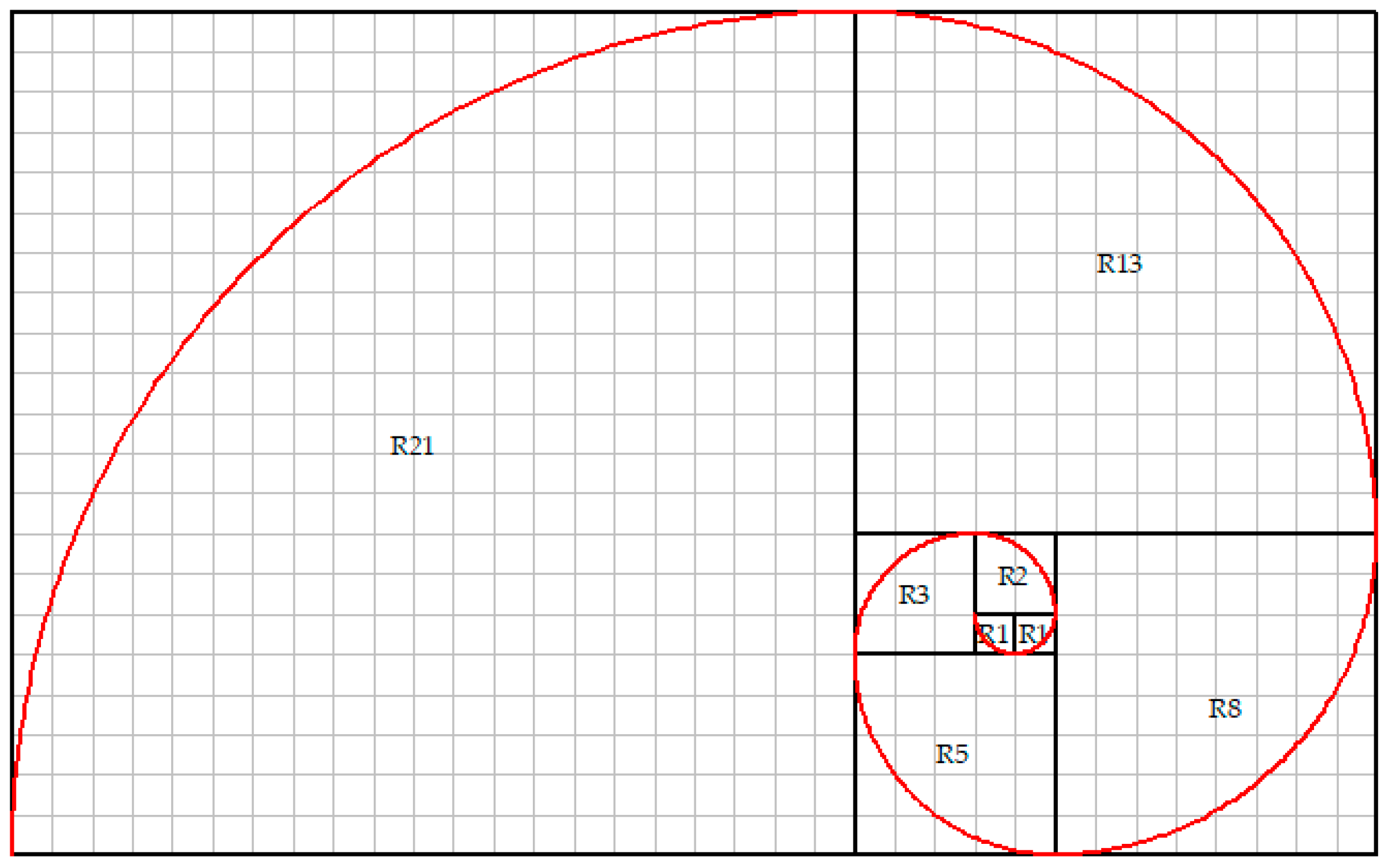
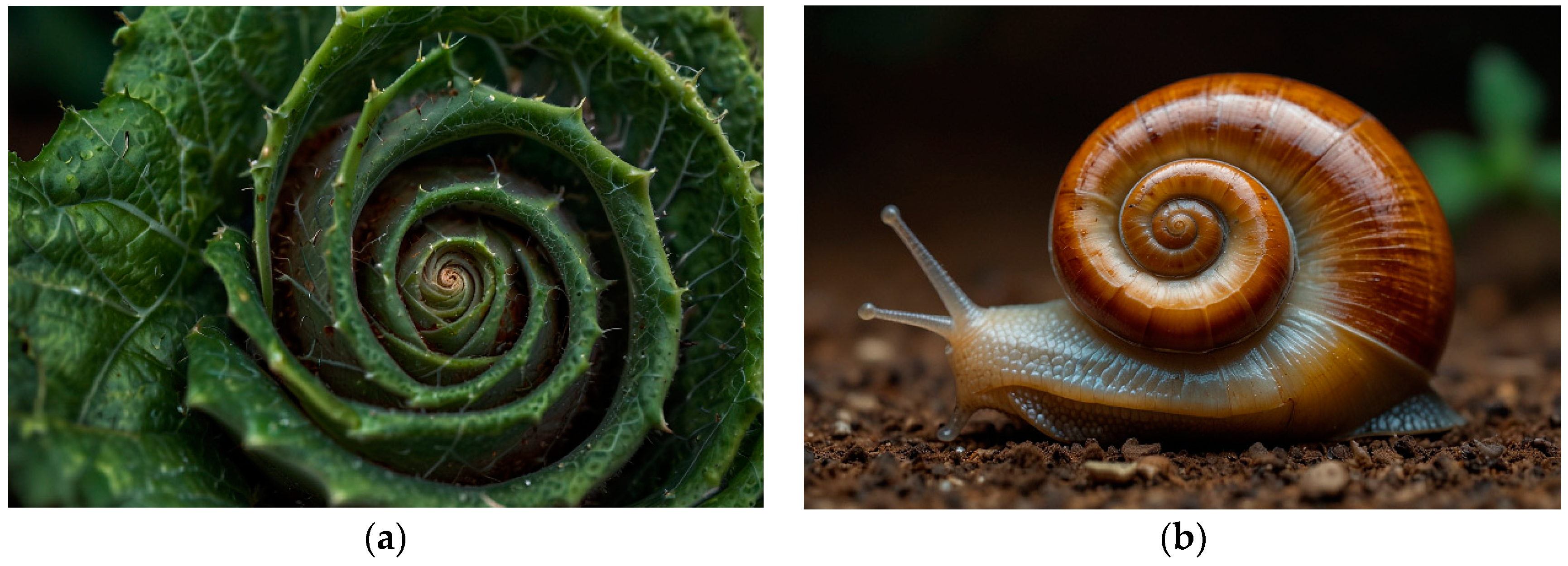
2.2. Biomimetic Design

Once the CFD model was validated, the present work proposed a new blade profile based on a biologically inspired shape. In engineering, the concept of bioinspiration or biomimicry, which draws inspiration from nature, is often an apt approach. This is because natural forms and processes have undergone countless years of evolution, resulting in highly efficient and optimized solutions to various challenges [30,31].
The turbine’s design, inspired by biomimicry principles, is meticulously crafted to efficiently harness energy from diminished hydrokinetic currents, addressing the pressing need for effective energy extraction under such conditions. The Fibonacci spiral was proposed as a solution to this problem. For comparison purposes, both Savonius and Fibonacci blade profiles are shown in Figure 5. As illustrated in this figure, the Savonius turbine is composed of semicircular profiles (red color dotted line). The Fibonacci spiral (black color dashed line), derived from the Fibonacci sequence, is a spiral characterized by a growth pattern where each number is the sum of the two preceding ones.
The Fibonacci spiral is a geometric pattern derived from the Fibonacci sequence, a series of numbers where each number is the sum of the two preceding ones (0, 1, 1, 2, 3, 5, 8, 13, 21, and so on). When these numbers are employed to generate a spiral, as illustrated in Figure 6, each segment of the spiral is proportional to a Fibonacci number, thereby conferring a distinctive spiral shape. The Fibonacci spiral is characterized by its distinctive properties, including self-similarity and the golden ratio. The golden ratio, approximately equal to 1.618, is a mathematical ratio that appears frequently in nature and art. In the Fibonacci spiral, the ratio of each successive segment’s length to the previous one approaches the golden ratio as the sequence progresses.
The spiral pattern is a common feature of various natural phenomena, as illustrated in Figure 7. Examples include the arrangement of seeds in a sunflower, the spiral shells of certain mollusks, and the branching patterns of trees.
In engineering, the Fibonacci spiral may be utilized to improve systems. When applied to the blade profile of a Savonius hydrokinetic turbine, the Fibonacci spiral offers several advantages. First, the spiral’s geometric properties, such as self-similarity and the golden ratio, contribute to an efficient and aerodynamic blade design, enhancing the turbine’s performance in capturing energy. Furthermore, the Fibonacci spiral-inspired blade profile improves the turbine’s efficiency in capturing kinetic energy from fluid flows. The use of the Fibonacci spiral as the blade profile for a Savonius turbine aligns with the principles of biomimicry, whereby natural patterns are employed to enhance the turbine’s performance and energy extraction capabilities.

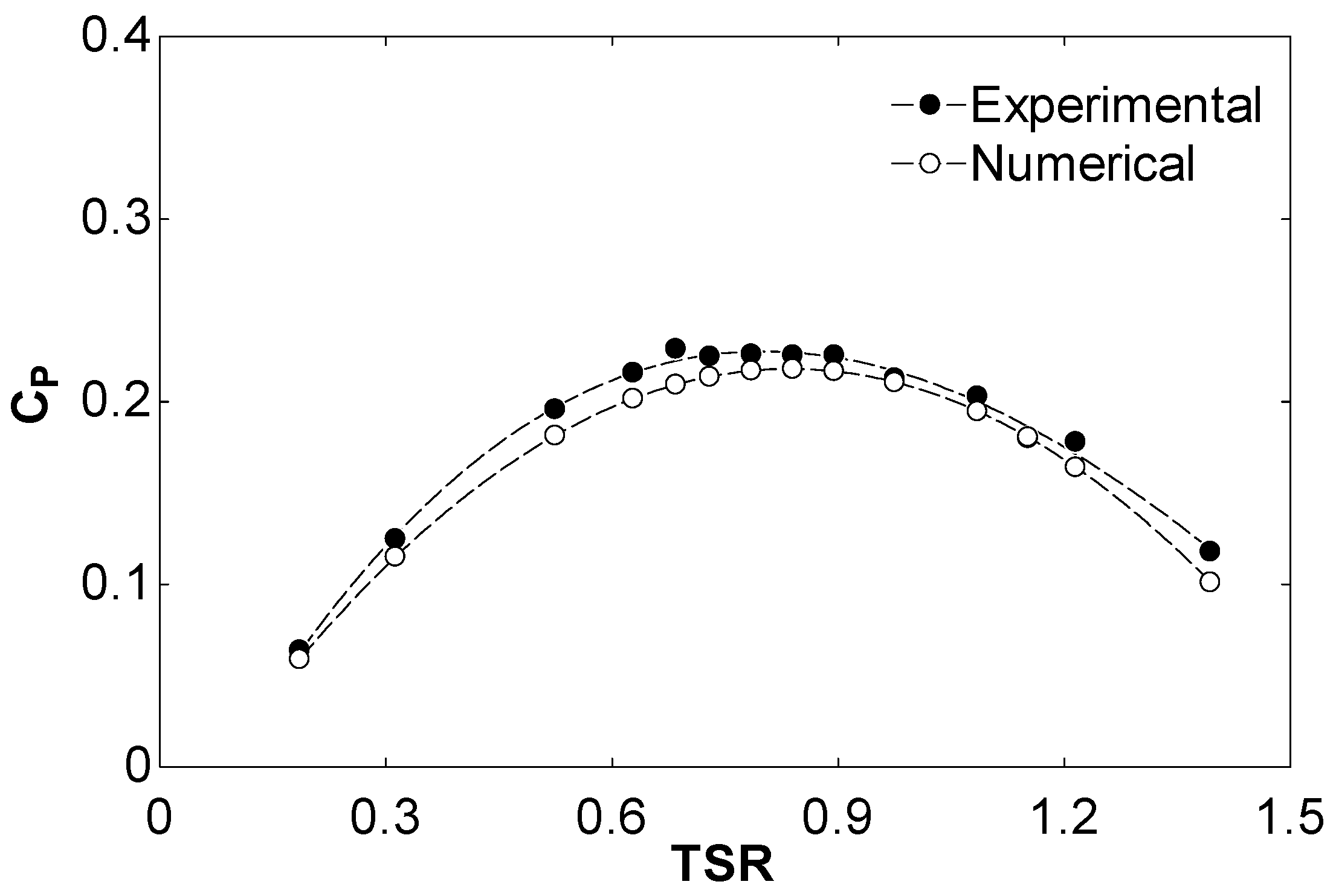
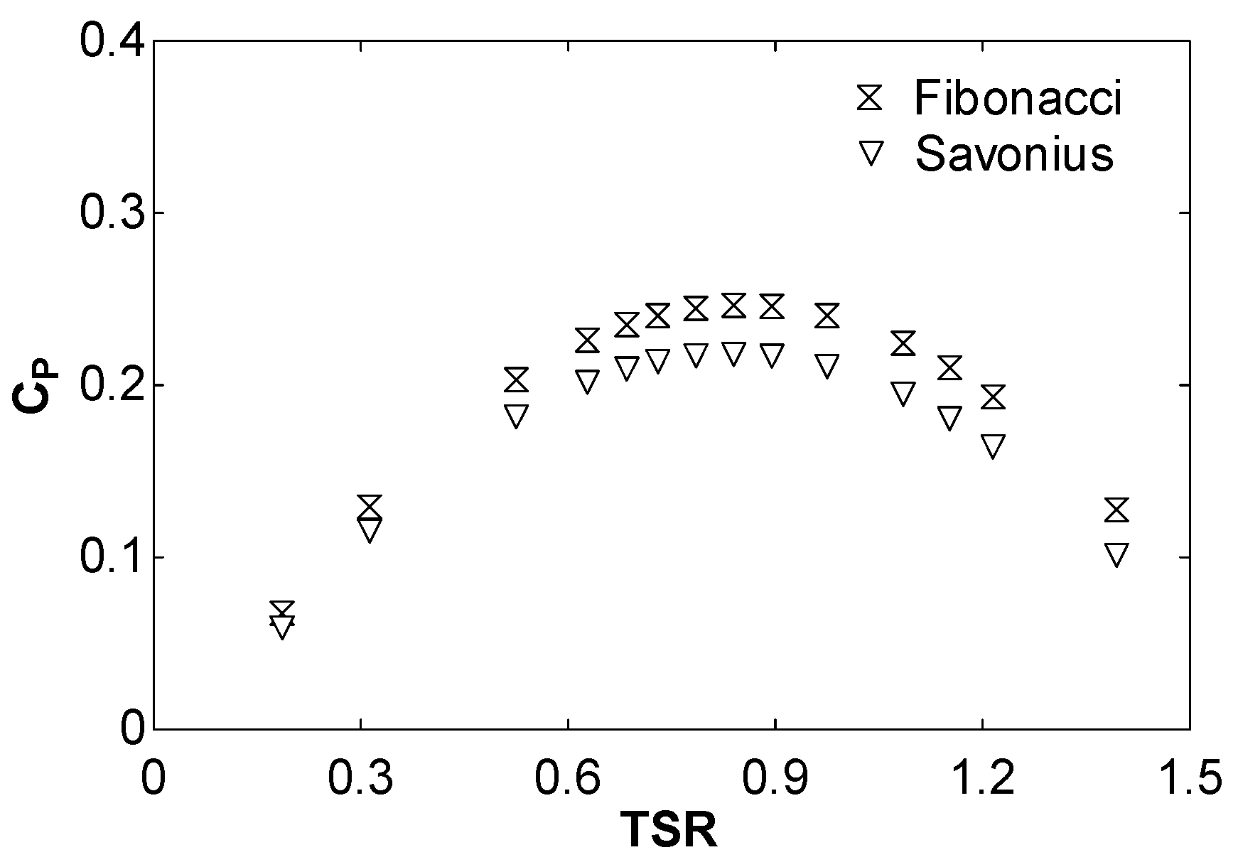
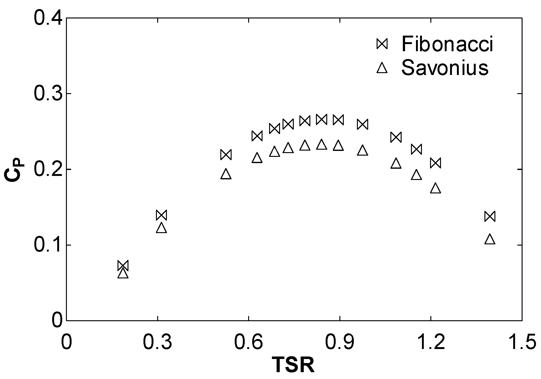
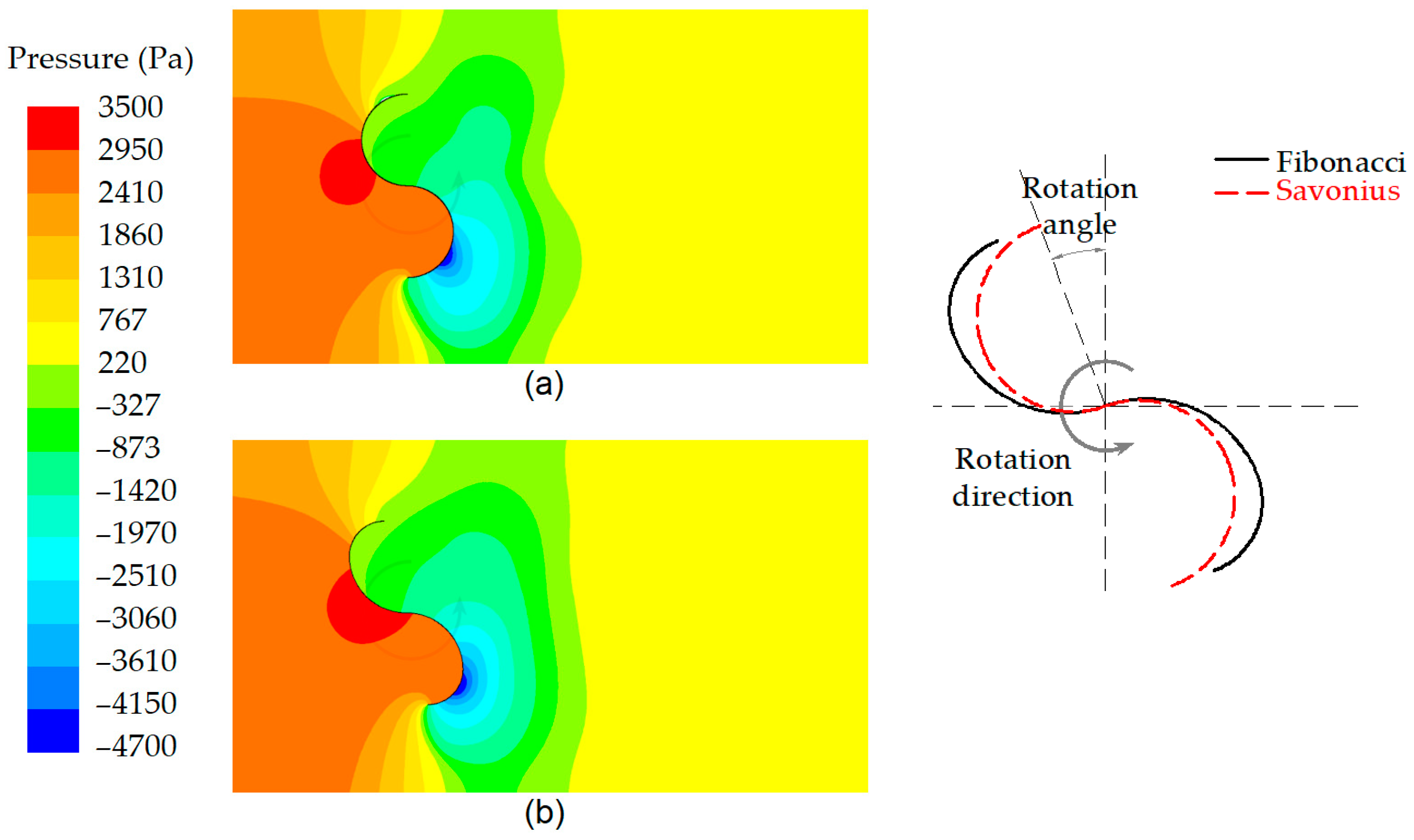
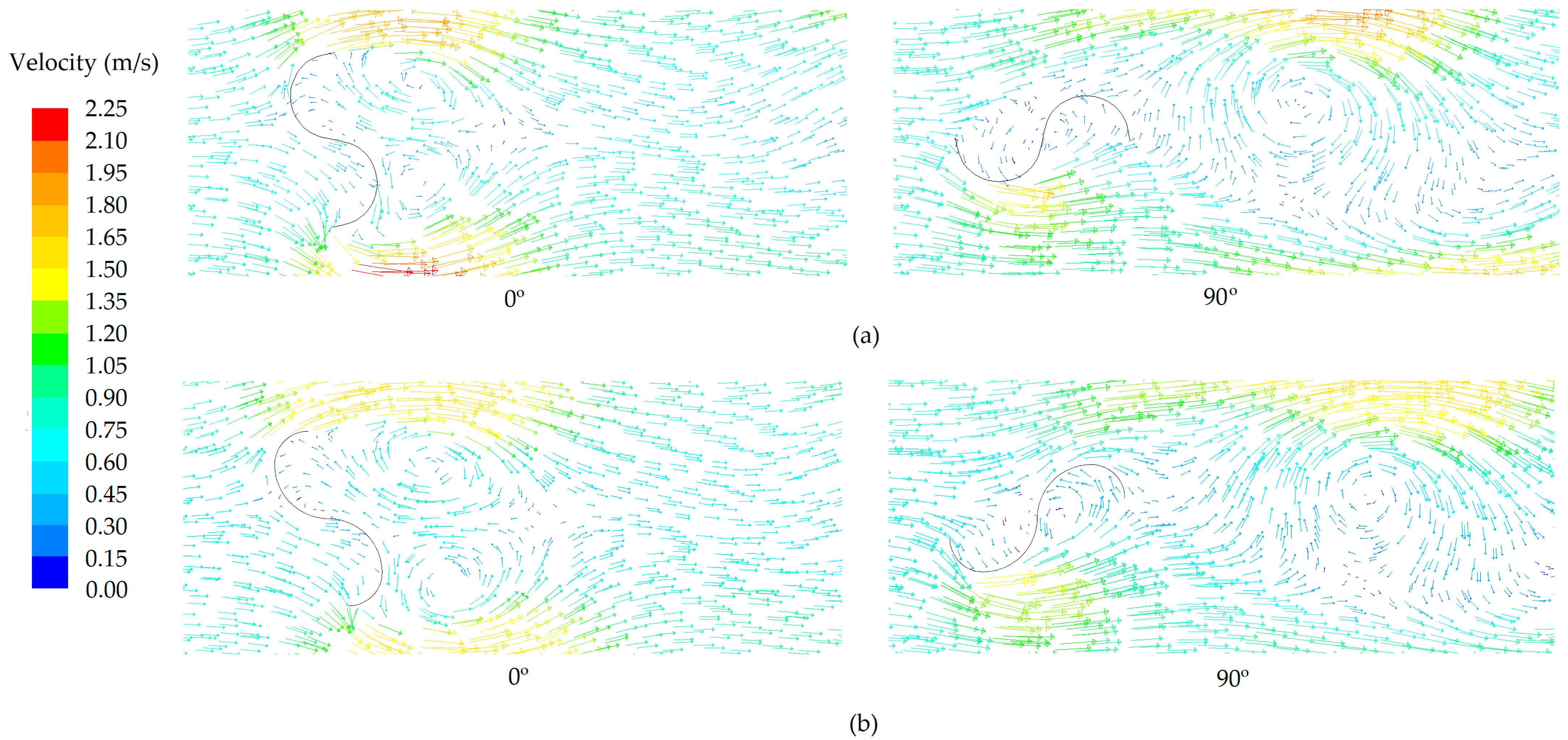
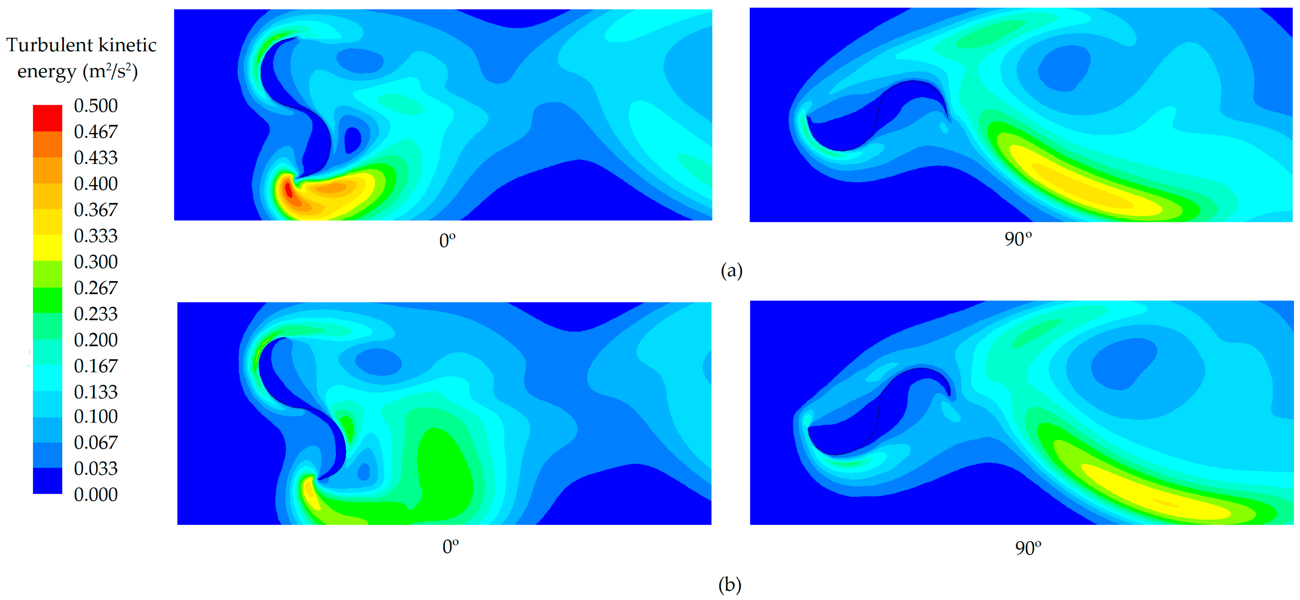
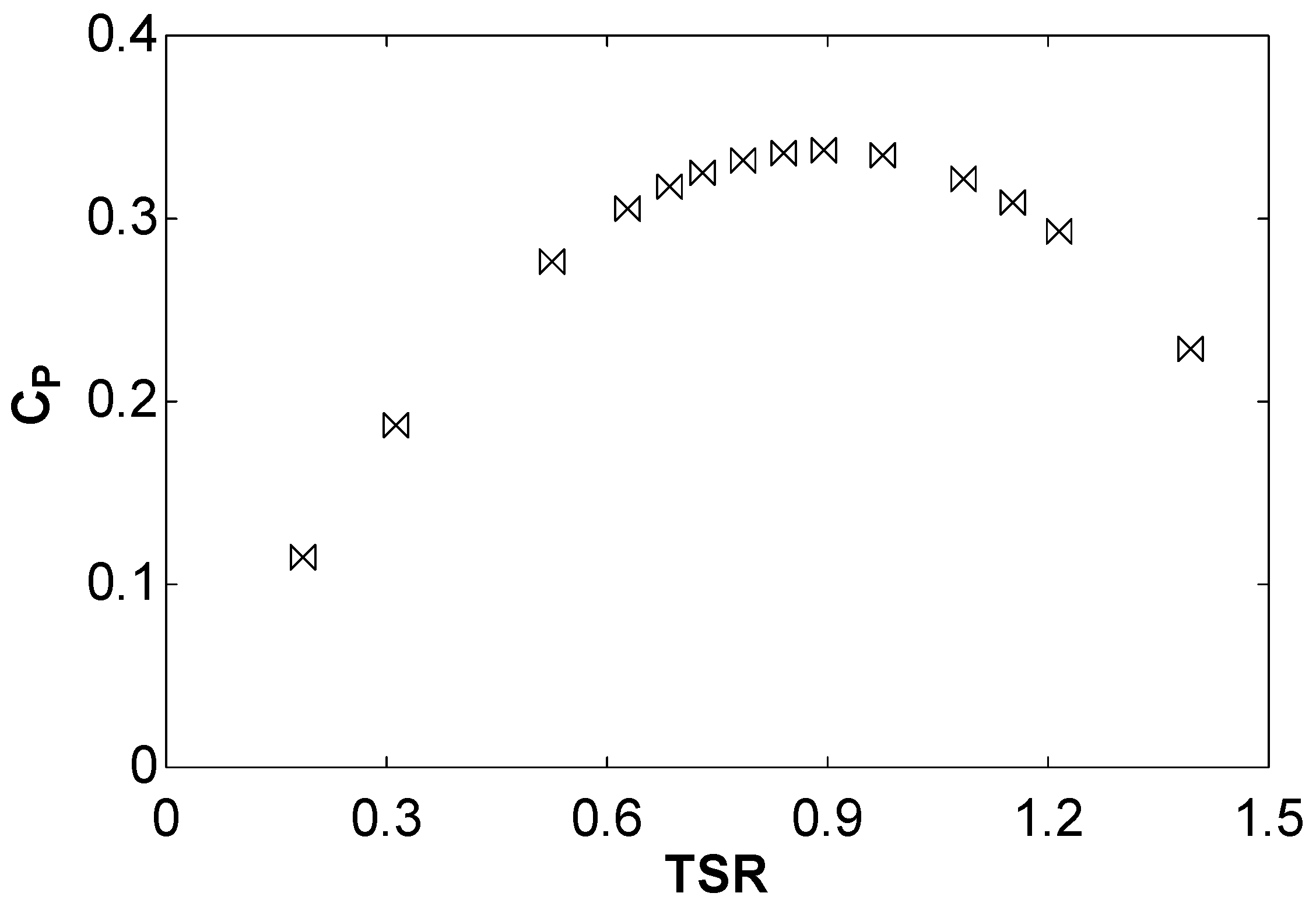
3. Results and Discussion

Figure 8 and Figure 9 illustrate the comparison of Fibonacci and Savonius blade profiles for air (wind turbine) and water (hydrokinetic turbine), respectively. These figures correspond to data obtained with the CFD model developed in the present work. In the simulations of Figure 8, air with a velocity of 7 m/s was implemented, corresponding to the experiments of Blackwell et al. [27]. In the simulations depicted in Figure 9, water with a velocity of 1 m/s was implemented.
Both Figure 8 and Figure 9 illustrate the enhanced performance of the Fibonacci blade profile in comparison to the traditional semi-circular Savonius blade profiles. This is due to the performance of the turbine. The turbine comprises a set of rotating blades arranged around a central shaft. In this design, one blade serves as the advancing blade, while the other blade functions as the returning blade. The advancing blade is characterized by a concave surface oriented towards the water flow, while the returning blade features a convex surface facing the water flow. In this configuration, the turbine primarily rotates due to the drag force between the concave and convex sides of the blades. The advancing blade experiences a greater drag force than the returning blade, resulting in the production of positive torque. In the Fibonacci design, the negative torque is reduced on the returning blade. This phenomenon is illustrated in the pressure field depicted in Figure 10. This figure compares the Savonius design with the Fibonacci design. As illustrated, the Fibonacci design provides a more concentrated flow on the concave blade and a reduced flow on the convex blade. The velocity field is shown in Figure 11, which shows the higher velocities in the advancing blade for the Fibonacci profile. In addition, the downstream velocities of the turbine are lower for the Fibonacci profile than for the Savonius profile, indicating a better conversion of the kinetic energy of the fluid into mechanical energy in the Fibonacci case. Figure 12 shows the turbulent kinetic energy (TKE) and Figure 13 shows the vorticity. As can be seen, the Fibonacci profile leads to lower values of TKE, resulting in less energy being dissipated due to viscous effects. Figure 13 shows a well-optimized design where the flow is efficiently directed around the blades, generating rotational motion without excessive chaotic fluctuations. This results in improved turbine performance and higher efficiency. Figure 10, Figure 11, Figure 12 and Figure 13 correspond to TSR = 0.85, Re = 9.96 × 10⁵, and a position of 0°. In this instance, the power coefficient is observed to be higher for the Fibonacci design than for the Savonius design. These figures illustrate a better hydrodynamic performance in the Fibonacci profile. The Reynolds number was computed using Equation (4), where ν is the kinematic viscosity of the fluid.
Re = VD ν
The power coefficient corresponding to Fibonacci and Savonius at other positions is shown in Figure 14, which represents the power coefficient along a full rotation (from 0 to 360°). Both the Savonius and Fibonacci blade profiles are illustrated in Figure 14. This figure corresponds to TSR = 0.85 and Re = 9.96 × 10⁵. This figure shows that there are angles of rotation for which the power coefficient of the Fibonacci profile is higher than that of the Savonius profile and angles of rotation where the opposite is true. The reason for this is that the optimal angle for the Savonius profile is slightly different from that of the Fibonacci profile. This discrepancy causes the maximum and minimum values of the power coefficient for the two profiles to not coincide. The average power coefficient in the rotation shown in Figure 14 is 0.266 for the Fibonacci profile and 0.231 for the Savonius profile, representing a 15.1% improvement. For these specific conditions, the lift/drag ratio increased from 0.16 to 0.22. For other TSR values, the results are very similar and therefore not presented again. The improved lift/drag ratio in the new design means improved hydrodynamic performance because lift contributes to the rotational force more efficiently than drag. In addition, reduced drag means less energy is wasted in overcoming resistance, allowing more energy to be converted into useful work. As a result, the kinetic energy of the fluid is better converted into mechanical energy.
Returning again to Figure 8 and Figure 9, another significant conclusion that can be drawn from them is that the power coefficient increases with a higher Reynolds number. The Reynolds number corresponding to the air case is 4.32 × 10⁵, while the corresponding one to the water case is 9.96 × 10⁵. To illustrate this phenomenon, several velocities have been analyzed. Specifically, Figure 15 illustrates the maximum power coefficient against the Reynolds number for a hydrokinetic turbine (water) under flow velocities from 0.2 to 1.5 m/s, corresponding to Reynolds numbers from approximately 2 × 10⁵ to 1.5 × 10⁵. The exact data are indicated in Table 3. As can be seen, these data corroborate that the power coefficient increments as the Reynolds number is incremented.
It is well known that the performance of a turbine can be improved by the aforementioned parameters, including the overlap, separation gap, and twist angle. In a previous study [26], the values corresponding to an aspect ratio of 7.5, an overlap of 0.1125, and a twist angle of 112° were proposed for a wind turbine. In the present study, these values were tested on a hydrokinetic turbine. The results are shown in Figure 16, which correspond to a Fibonacci hydrokinetic turbine with these values of the aspect ratio, overlap, and twist angle. As can be seen, the maximum power coefficient is 0.337, representing a 26.7% improvement in comparison with the 0.266 value corresponding to an aspect ratio of 1, an overlap of 0, and a twist angle of 0.

4. Conclusions

The present work concerns a novel design intended to enhance the performance of the Savonius turbine for hydrokinetic applications. These types of turbines were selected due to their independence of the fluid direction and favorable starting characteristics. In certain regions, low-speed currents with considerable energy are present, yet the water velocities are relatively low. This is particularly evident in low-flow water environments, such as rivers, streams, and tidal channels. In such settings, conventional turbines may not be a viable option due to the insufficient water velocity. Savonius turbines are capable of self-starting at very low fluid velocity. In terms of environmental sensitivity, Savonius turbines have a minimal environmental impact compared to large-scale hydroelectric dams or fossil fuel-based power generation. These turbines do not result in significant alterations to the water, making them suitable for environmentally sensitive areas where the preservation of natural habitats is a priority.
A blade design based on the Fibonacci spiral was proposed through the observation and the understanding of biological systems. This design was then analyzed through CFD. Current velocities between 0.2 and 1.5 m/s were analyzed, and the proposed design demonstrated a promising potential for sustainable energy generation in these low-flow-velocity conditions. The results demonstrate a notable improvement, with a 15.1% increase in the power coefficient compared to that of the traditional Savonius turbine. Further modifications were made to the overlap, separation gap, and twist angle in order to achieve an even greater increase in the power coefficient. The power coefficient was increased by 26.7% compared to 0.266, corresponding to an aspect ratio of 1, an overlap of 0, and a twist angle of 0 when an aspect ratio of 7.5, an overlap of 0.1125, and a twist angle of 112° were used. Other improvements, such as augmentation devices like deflectors, would also increase the power coefficient, a topic that will be subject to future research. Another potential avenue for enhancing performance is the design of a multi-stage turbine to capture a greater portion of the energy in the flow. Future work must also address the practical challenges associated with manufacturing a Savonius rotor with Fibonacci spiral blades. According to the present results, in practical applications, it is suggested to optimize the blade shape, overlap ratio, aspect ratio, and helicoidality. Incorporating flow augmentation devices such as deflectors is also recommended. A key economic consideration must be addressed in order to compare the manufacturing costs. Other important factors include vibration, stress, fatigue, robustness, stability, and durability analysis.

Author Contributions

Conceptualization, J.M.R.L.; methodology, M.I.L.G. and J.B.D.; software, M.I.L.G. and J.B.D.; validation, J.d.D.R.G., C.G.C. and A.C.C.; formal analysis, J.d.D.R.G., C.G.C. and A.C.C.; investigation, J.M.R.L., M.I.L.G., J.d.D.R.G., C.G.C., J.B.D., J.T.M. and A.C.C.; resources, J.M.R.L., M.I.L.G., J.d.D.R.G., C.G.C., J.B.D., J.T.M. and A.C.C.; writing—original draft preparation, J.M.R.L., M.I.L.G., J.d.D.R.G., C.G.C., J.B.D., J.T.M. and A.C.C.; writing—review and editing, J.M.R.L., M.I.L.G., J.T.M. and A.C.C.; supervision, J.d.D.R.G., C.G.C. and J.B.D. All authors have read and agreed to the published version of the manuscript.

Funding

This research received no external funding.

Institutional Review Board Statement

Not applicable.

Informed Consent Statement

Not applicable.

Data Availability Statement

Data are contained within the article.

Conflicts of Interest

The authors declare no conflicts of interest.

References

  1. Jacobson, P. Assessment and Mapping of the Riverine Hydrokinetic Energy Resource in the Continental United States; Technical Report; Electric Power Research Institute: Palo Alto, CA, USA, 2012. [Google Scholar]
  2. Quaranta, E.; Bodis, K.; Kasiulis, E.; McNabola, A.; Pistocci, A. Is There a Residual and Hidden Potential for Small and Micro Hydropower in Europe? A Screening-Level Regional Assessment. Water Resour. Manag. 2022, 36, 1745–1762. [Google Scholar] [CrossRef]
  3. Calero Quesada, M.C.; García Lafuente, J.; Sánchez Garrido, J.C.; Sammartino, S.; Delgado, J. Energy of marine currents in the Strait of Gibraltar and its potential as a renewable energy resource. Renew. Sustain. Energy Rev. 2014, 34, 98–109. [Google Scholar] [CrossRef]
  4. Behrouzi, F.; Nakisa, M.; Maimun, A.; Ahmed, Y. Global renewable energy and its potential in Malaysia: A review of hydrokinetic turbine technology. Renew. Sustain. Energy Rev. 2016, 62, 1270–1281. [Google Scholar] [CrossRef]
  5. Brasil, A.; Mendes, R.; Wirrig, T.; Noguera, R.; Oliveira, T. On the design of propeller hydrokinetic turbines: The effect of the number of blades. J. Braz. Soc. Mech. Sci. Eng. 2019, 41, 1–14. [Google Scholar] [CrossRef]
  6. Vaz, J.; Lima, A.; Lins, E. Assessment of a diffuser-augmented hydrokinetic turbine designed for harnessing the flow energy downstream of dams. Sustainability 2023, 15, 7671. [Google Scholar] [CrossRef]
  7. Khan, M.J.; Bhuyan, G.; Iqbal, M.T.; Quaicoe, J.E. Hydrokinetic energy conversion systems and assessment of horizontal and vertical axis turbines for river and tidal applications: A technology status review. Appl. Energy 2009, 89, 1823–1835. [Google Scholar] [CrossRef]
  8. Kumar, A.; Saini, R.P. Performance parameters of Savonius type hydrokinetic turbine—A Review. Renew. Sustain. Energy Rev. 2016, 64, 289–310. [Google Scholar] [CrossRef]
  9. Singh, S.V.; Kumar, P. Study of flow characteristics of a Savonius turbine inside nozzle diffuser duct. J. Eng. Res. 2022. [Google Scholar] [CrossRef]
  10. Susilo, R.D.; Gunawan, G.; Kurniawati, D.M. Testing the effect of variation of deflector shapes on the performance of the three blade vertical axis Savonius water turbine. J. Tek. Energi 2022, 18, 115–118. [Google Scholar]
  11. Katayama, Y.; Watanabe, S.; Tsuda, S. Influence of distance from water surface of a horizontally installed Savonius turbine in a rectangular open channel on turbine performance. J. Phys. Conf. Ser. 2022, 2217, 012042. [Google Scholar] [CrossRef]
  12. Sood, M.; Singal, S.K. Development of hydrokinetic energy technology: A review. Int. J. Energy Res. 2019, 43, 5552–5571. [Google Scholar] [CrossRef]
  13. Patel, V.; Bhat, G.; Eldho, T.I.; Prabhu, S.V. Influence of overlap ratio and aspect ratio on the performance of Savonius hydrokinetic turbine. Int. J. Energy Res. 2016, 41, 829–844. [Google Scholar] [CrossRef]
  14. Barbarić, M.; Guzović, Z. Investigation of the possibilities to improve hydrodynamic performances of micro-hydrokinetic turbines. Energies 2020, 13, 4560. [Google Scholar] [CrossRef]
  15. Mejia, O.D.; Mejia, O.E.; Escorcia, K.M.; Suarez, F.; Lain, S. Comparison of sliding and overset mesh techniques in the simulation of a vertical axis turbine for hydrokinetic applications. Processes 2021, 9, 1933. [Google Scholar] [CrossRef]
  16. Fertahi, S.; Bouhal, T.; Rajad, O.; Kousksou, T.; Arid, A.; El Rhafiki, T.; Jamil, A.; Benbassou, A. CFD performance enhancement of a low cut-in speed current vertical tidal turbine through the nested hybridization of Savonius and Darrieus. Energy Convers. Manag. 2018, 169, 266–278. [Google Scholar] [CrossRef]
  17. Talukdar, P.K.; Sardar, A.; Kulkarni, V.; Saha, U.K. Parametric analysis of model Savonius hydrokinetic turbines through experimental and computational investigations. Energy Convers. Manag. 2018, 158, 36–49. [Google Scholar] [CrossRef]
  18. Tian, W.; Mao, Z.; Zhang, B.; Li, Y. Shape optimization of a Savonius wind rotor with different convex and concave sides. Renew. Energy 2018, 113, 287–299. [Google Scholar] [CrossRef]
  19. Kumar, A.; Saini, R.P. Performance analysis of a single stage modified Savonius hydrokinetic turbine having twisted blades. Renew. Energy 2017, 113, 461–478. [Google Scholar] [CrossRef]
  20. Sarma, N.K.; Biswas, A.; Misra, R.D. Experimental and computational evaluation of Savonius hydrokinetic turbine for low velocity condition with comparison to Savonius wind turbine at the same input power. Energy Convers. Manag. 2014, 83, 88–98. [Google Scholar] [CrossRef]
  21. Samadi, M.; Hassanabad, M.G.; Mozafari, S.B. Performance enhancement of low speed current Savonius tidal turbines through adding semi-cylindrical deflectors. Ocean Eng. 2022, 259, 111873. [Google Scholar] [CrossRef]
  22. Wahyudi, B.; Soeparman, S.; Hoeijmakers, H.W.M. Optimization design of Savonius diffuser blade with moving deflector for hydrokinetic cross flow turbine rotor. Energy Procedia 2015, 68, 244–253. [Google Scholar] [CrossRef]
  23. Golecha, K.; Eldho, T.I.; Prabhu, S.V. Influence of the deflector plate on the performance of modified Savonius water turbine. Appl. Energy 2011, 88, 3207–3217. [Google Scholar] [CrossRef]
  24. Damota, J.; Lamas, I.; Couce, A.; Rodriguez, J. Vertical axis wind turbines: Current technologies and future trends. Renewable Energy Power Qual. J. 2015, 1, 530–535. [Google Scholar] [CrossRef]
  25. Blanco Damota, J.; Rodriguez, J.D.; Couce, A.; Lamas, M.I. Proposal of a nature-inspired shape for a vertical axis wind turbine and comparison of its performance with a semicircular blade profile. Appl. Sci. 2021, 11, 6198. [Google Scholar] [CrossRef]
  26. Blanco Damota, J.; Rodríguez García, J.D.D.; Couce Casanova, A.; Telmo Miranda, J.; Caccia, C.G.; Galdo, M.I.L. Optimization of a nature-inspired shape for a vertical axis wind turbine through a numerical model and an artificial neural network. Appl. Sci. 2022, 12, 8037. [Google Scholar] [CrossRef]
  27. Blackwell, B.F.; Sheldahl, R.E.; Feltz, L.V. Wind Tunnel Performance Data for Two- and Three-Bucket Savonius Rotors; Sandia Laboratories: Springfield, VA, USA, 1977. [Google Scholar]
  28. Damota, J.B.; García, J.D.; Casanova, A.C.; Miranda, J.T.; Caccia, C.G.; Galdo, M.I.L. Analysis of a nature-inspired shape for a vertical axis wind turbine. Appl. Sci. 2022, 12, 7018. [Google Scholar] [CrossRef]
  29. Blanco Damota, J. Perfil de pala de Turbina eólica de eje Vertical de Diseño Bioinspirado: Estudio Comparativo y Optimización Mediante Modelo CFD Parametrizado. Ph.D. Thesis, Unviersidade da Coruña, La Coruna, Spain, 2022. [Google Scholar]
  30. Lamas, M.I.; Rodríguez, J.D.; Rodríguez, C.G.; González, P.B. Three-dimensional CFD analysis to study the thrust and efficiency of a biologically-inspired marine propulsor. Pol. Marit. Res. 2011, 18, 10–16. [Google Scholar] [CrossRef]
  31. Lamas Galdo, M.I.; Rodriguez Vidal, C.G. Hydrodynamics of biomimetic marine propulsion and trends in computational simulations. J. Mar. Sci. Eng. 2020, 8, 479. [Google Scholar] [CrossRef]
Figure 1. (a) Savonius turbine; (b) main parameters; (c) twist angle.
Jmse 12 01312 g001
Figure 2. Computational domain.
Jmse 12 01312 g002
Figure 3. Computational mesh; (a) 3D and section in the mid-plane; (b) mesh at the blade’s surface.
Jmse 12 01312 g003
Figure 4. Power coefficient corresponding to the experimental and numerical results [25]. Wind turbine (air).
Jmse 12 01312 g004
Figure 5. Fibonacci and Savonius shapes.
Jmse 12 01312 g005
Figure 6. Fibonacci spiral with radius.
Jmse 12 01312 g006
Figure 7. Instances of the Fibonacci spiral occurring in nature: (a) vegetal; (b) animal.
Jmse 12 01312 g007
Figure 8. Power coefficient against the tip speed ratio. Wind turbine (air), flow velocity 7 m/s, Re = 4.32 × 10⁵.
Jmse 12 01312 g008
Figure 9. Power coefficient against the tip speed ratio. Hydrokinetic turbine (water), flow velocity 1 m/s, Re = 9.96 × 10⁵.
Jmse 12 01312 g009
Figure 10. Pressure field (Pa) corresponding to the 0° position; (a) Savonius blade profile; (b) Fibonacci blade profile. Hydrokinetic turbine (water), flow velocity 1 m/s, Re = 9.96 × 10⁵, TSR = 0.85.
Jmse 12 01312 g010
Figure 11. Velocity field (m/s) corresponding to 0° and 90° positions; (a) Savonius blade profile; (b) Fibonacci blade profile. Hydrokinetic turbine (water), flow velocity 1 m/s, Re = 9.96 × 10⁵, TSR = 0.85.
Jmse 12 01312 g011
Figure 12. Turbulent kinetic energy field (m2/s2) corresponding to 0° and 90° positions; (a) Savonius blade profile; (b) Fibonacci blade profile. Hydrokinetic turbine (water), flow velocity 1 m/s, Re = 9.96 × 10⁵, TSR = 0.85.
Jmse 12 01312 g012
Figure 13. Vorticity field (s−1) corresponding to 0° and 90° positions; (a) Savonius blade profile; (b) Fibonacci blade profile. Hydrokinetic turbine (water), flow velocity 1 m/s, Re = 9.96 × 10⁵, TSR = 0.85.
Jmse 12 01312 g013
Figure 14. Power coefficient against the rotation angle. Hydrokinetic turbine (water), flow velocity 1 m/s, Re = 9.96 × 10⁵, TSR = 0.85.
Jmse 12 01312 g014
Figure 15. Maximum power coefficient against Reynolds. Hydrokinetic turbine (water); flow velocity from 0.2 to 1.5 m/s.
Jmse 12 01312 g015
Figure 16. Power coefficient against the tip speed ratio. Hydrokinetic turbine (water), flow velocity 1 m/s, Re = 9.96 × 10⁵. Aspect ratio 7.5, overlap 0.1125, twist angle 112°.
Jmse 12 01312 g016
Table 1. Computational setup.
Governing EquationsReynolds-Averaged Navier–Stokes (RANS)
Turbulence modelSST k-ω
Pressure–velocity couplingPIMPLE
Temporal treatmentImplicit
Spatial discretizationSecond order
Convergence criterion10−3
Table 2. Meshes analyzed.
MeshElementsReCP
11.5 × 106199,2300.226
22.9 × 106398,4600.212
33.8 × 106996,1490.207
44.5 × 1061,494,2230.207
Table 3. Maximum power coefficient against Reynolds.
V (m/s)ReCPmax
Case 10.2199,2300.240
Case 20.4398,4600.249
Case 31996,1490.266
Case 41.51,494,2230.270
Disclaimer/Publisher’s Note: The statements, opinions and data contained in all publications are solely those of the individual author(s) and contributor(s) and not of MDPI and/or the editor(s). MDPI and/or the editor(s) disclaim responsibility for any injury to people or property resulting from any ideas, methods, instructions or products referred to in the content.

