Article

Experimental and Numerical Investigation on the Motion Responses of a Spar-Type Floating Structure with Aquaculture Feeding Systems

1
Department of Systems Design for Ocean-Space, Faculty of Engineering, Yokohama National University, 79-5 Tokiwadai, Hodogaya-ku, Yokohama 240-8501, Japan
2
Department of Systems Innovation, Graduate School of Engineering, The University of Tokyo, 5-1-5 Kashiwanoha, Chiba 277-8574, Japan
3
Institute of Industrial Science, The University of Tokyo, 5-1-5 Kashiwanoha, Chiba 277-8574, Japan
*
Author to whom correspondence should be addressed.
J. Mar. Sci. Eng. 2024, 12(8), 1329; https://doi.org/10.3390/jmse12081329
Submission received: 24 June 2024 / Revised: 23 July 2024 / Accepted: 4 August 2024 / Published: 6 August 2024

Abstract

:
The combination of aquaculture industry with floating offshore wind turbines has the potential to generate significant economic advantages for both industries. To investigate this potential, the present study focuses on analyzing the heave, and pitch dynamic responses of a Spar-type floating offshore wind turbine that incorporates an aquaculture feeding system. A series of water tank model tests, together with numerical calculations, were conducted using a 1/56 scale model of a 2 MW, displacement 3500 tons, floating Spar-type wind turbine. The feeding system was placed inside the Spar and slightly above the waterline by adjusting the configuration of the total weight. The weight of the feeding system in the experiments is 100 tons, capable of sustaining 300 tons of fish for an entire week, and the realistic applications have been expanded using the numerical calculation. For this reason, the present study serves a good case study for general understanding, because the integration of the feeding system inevitably raises the center of gravity of the structure and potentially affects its overall stability. The experiments revealed no discernible increase in the heave motion. Moreover, the pitch motion theoretically increased, but occasionally decreased in the experiments with the overall inclination angles being less than 1.2 degrees during the experiments. As a result, the present study supports the practice of integrating a Spar-type wind turbine with feeding systems. Future research should continue to comprehensively examine, both experimentally and numerically, the motion responses of the wind turbine and aquaculture facilities with varying configurations.

1. Introduction

Offshore marine aquaculture, which is located in deeper and less protected areas than coastal ones, gains increasing popularity as mariculture develops. Coastal marine aquaculture suffers from self-pollution [1], and open ocean exhibits advantages regarding the environmental burden of aquaculture operations. Open waters make fish farms and cultivated fish more exposed to stronger oceanic currents and a greater variety of nutrient fluxes [2], causing decreased pollution levels and increased oxygen availability [3].
One difficulty always faced by offshore aquaculture system lies in the construction of a strong and resilient system that can withstand the harsh and extreme conditions of open waters, particularly in the face of potential typhoon attacks. Recently, very large offshore cages have been proposed and practiced in open waters. SalMar and its subsidiary Ocean Farming, in Norway, are at the forefront of the commercial offshore aquaculture industry [4]. Similarly, the Deep Blue 1, located at 222.2 km from the Dongjiakou Port, China, was reported to accommodate 200,000 salmon individuals [5]. Meanwhile, feeding systems are required to upgrade due to the long distance from the coastline, such as the usage of an automated feeder. For example, an automated buoy carrying feed of 750 kg has been examined with a hybrid solar and wind power system [6]. Also, the concept of an offshore aquaculture system using a floating feeding system connected via hoses has been experimentally and numerically investigated [7]. However, these buoys have not been utilized until now due to a lack of stable platforms. One potential solution is the introduction of offshore wind energy, because the relatively stable structures of wind turbines provide platforms for feeding systems.
Three conceptual plans have been proposed to integrate offshore wind energy and aquaculture effectively, based on the engineering [8] and economic [9] feasibility of aquaculture cages implemented in offshore wind farm areas. The first plan involves placing aquaculture facilities either at the foundations of wind turbines or in the space between them. This concept entails installing aquaculture facilities adjacent to wind turbine foundations, which can also serve as artificial fish reefs [10]. Importantly, this plan does not require any modifications to the existing wind farms [11], even including operation and maintenance such as crew transfer vessels, and meanwhile, aquaculture facilities can be constructed to serve dual purposes—aquaculture activities and energy generation [12]. Examples include a combined structure of a fixed monopile wind turbine foundation with a circular aquaculture cage [13]. The second plan involves modifying wind turbines to incorporate aquaculture components. In this case, the design of wind turbines must consider their dual purposes of generating energy and supporting aquaculture activities. For example, space can be allocated for fish cages at the foundations of bottom-mounted wind turbines [14]. Furthermore, it has been suggested that fish cages could be constructed using the buoyant materials of floating wind turbines [15], to optimize the aquaculture production and renewable energy usage in reality [16]. The third option involves utilizing wind turbines to generate power specifically for large-scale offshore aquaculture farms [17]. In this scenario, the electricity generated by wind turbines is stored and utilized locally, without being transferred to land [18]. These approaches can enable the automation and remote control of aquaculture operations using wind-generated power [19,20].
Among the above conceptual plans, current studies have extensively examined the second one, i.e., by modifying wind turbines to incorporate aquaculture components. Li et al. introduced a novel integrated design which combines a jacket-supported offshore wind turbine with an adjustable steel cage [21]. Compared to the bottom-mounted type of offshore wind turbines, its floating type shows higher adaptability. Zheng et al. introduced a novel concept of integrating floating wind-solar energy with aquaculture. They incorporated multi vertical-axis wind turbines (VAWT) and solar panels with a steel fish cage and examined the nonlinear stochastic responses of this system to wind-wave actions [22]. However, the horizontal axis wind turbines are still the most used because of their efficiency and reliability compared to VAWTs. Cao et al. experimentally examined an innovative semi-submersible floating wind turbine with aquaculture cages [23]. Subsequently, Lei et al. numerically validated the dynamic responses of a floating offshore wind turbine settled on a steel fish cage [24]. More recently, shared mooring lines have also been focused on, and for example, the effects of shared mooring lines have been numerically examined on the hydrodynamic response of a Spar-type wind turbine combined with a semi-submersible fish cage [25].
However, the impacts of feeding systems have not been fully investigated yet. Herein, we propose an offshore wind turbine-aquaculture system with a Spar-type floating wind turbine in its center (Figure 1: AI picture made by the Adobe Firefly). This figure illustrates a feeding system for submersible fish cages, which is a more practical integration approach. However, the purpose of this study is to examine how the integration could impact the Spar’s motion. As a result, the feeding system was intended to be positioned above the water’s surface; Section 2 provides further information on this. The Spar-type has been selected because it has higher sensitivity to the effects of additional feeding systems when compared to the other types. Fish farms are separately situated to form a multibody floating system, considering practical operations and maintenance. The current project aims to propose a practical integrated system with a minimal effect to wind turbines. Particularly, the introduction of additional components like feeding systems (consisting of feeders, silos, and other equipment) might elevate the floating wind turbine’s center of gravity. The change could potentially impact the turbine’s static and dynamic stability in waves. In this work, we performed water tank experiments to understand how a feeding system attached to a Spar-type floating wind turbine influences its motions in regular waves, and we discussed the results with numerical calculations.

2. Water Tank Experiment

2.1. Model Specifications

The target offshore floating wind turbine is based on Japan’s inaugural and economically viable floating wind farm—the “Sakiyama 2 MW Floating Offshore Wind Farm”—in Goto City, Nagasaki Prefecture [26,27,28,29]. The wind turbine itself is a Spar-type floating structure with a displacement capacity of 3500 tons, secured in position through a three-point catenary mooring system (Table 1). The Spar-type floating structure consists of two cylindrical pipes, and these pipes are connected by a cone-shape pipe. All distances and heights are calculated based on the bottom of the Spar. Three identical chains of different lengths were used in the experiment. In this study, we investigated hydrodynamic responses without wind load, and therefore, the scaled model was built based on the prototype without blade segments. The Froude number with a scale ratio of 1/56, given the size of the water tank as in Section 2.2, was considered in the model construction (Table 1). The model was assumed to be a rigid body without hydroelasticity, ignoring the similarity of structural stiffness. Also, the viscosity on the surface of the scaled model was not reproduced due to the difference in Reynolds number between a scaled and full-scale floating structure. Polyvinyl chloride pipes were selected to make the model given the material’s commercial availability and the relative ease of construction.
The feeding system is an essential component of the offshore wind turbine-aquaculture system, and investigations have been conducted on how the installation of the feeding system affects the motion of the floating wind turbine. The scaled feeding system adopted a 1/56 scale ratio following that of the Spar, and a 100-ton feeding system was assumed in the experiments (Table 1). The mass of the feeding system encompasses 50 tons of inherent self-weight and an additional 50 tons of food provisions. Note that this amount of food is roughly equivalent to what is required to feed 300 tons of farmed fish for at least one week. Because the maximum biomass of a general 20 m diameter cage is approximately 100 tons, three cages can be installed near the floating wind turbine. The feeding system, being placed slightly above the water surface to study the effects on the Spar’s motion, can be installed inside or outside the wind turbine’s tower. We opted the inside type to minimize the impacts on the wind resistance of the Spar. The motion responses of the floating body are inevitably influenced due to the installation of feeding systems and subsequent modification on the floating body’s center of gravity.
In this work, different installation heights were prepared to meet the requirements of various cage types, such as floated or submerged cages. The full-scale installation height was initially set to 1.0 m above the water surface, to analyze the effects of its installation on the Spar’s motions. Subsequently, the full-scale installation heights were adjusted to 6.0 m and 12.0 m, respectively, to investigate the effects of installation heights on the Spar’s motions.

2.2. Experimental Conditions

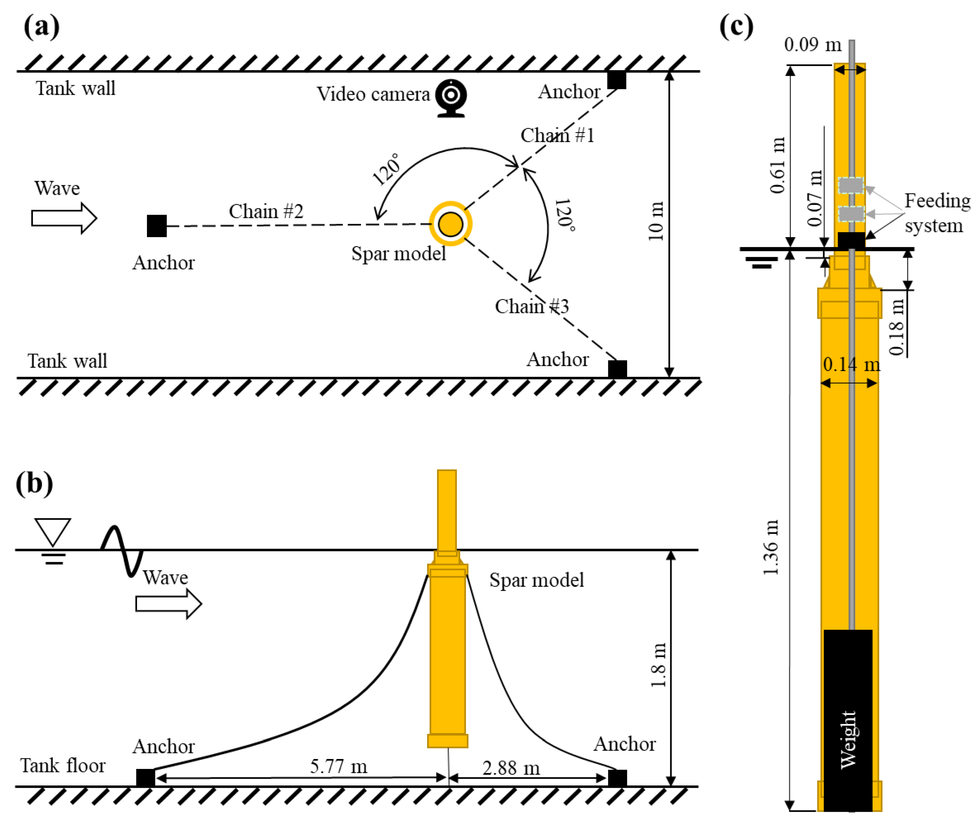
Experiments were conducted in the Ocean Engineering Basin at the Institute of Industrial Science, the University of Tokyo. The water tank is 50.0 m in length, 10.0 m in width, and 5.0 m in depth. Considering the full-scale installation depth at approximately 100 m, the experimental water depth was set to 1.8 m by elevating the tank floor (Figure 2 and Figure 3). The mooring system for the model replicated the actual three-point catenary mooring system with three 10 kg anchors. The effects of feeding systems were introduced via weight re-configuration, where the total weight and displacement of the Spar model remained identical. Note that the upper cylindrical pipe includes the draft of floating foundations and the hub of the Spar, based on the convenience of the model construction.
The typical period between actual ocean waves is 3 s to 15 s, and long wave periods lasting more than 30 s can be induced by fluctuations in atmospheric pressure [26]. Following Froude’s model law and the scale ratio of 1/56 here, the wave period of 5.25 s to 30 s in the real sea, which already includes both normal and extreme weather conditions, corresponds to that of 0.7 s to 4.0 s in the model experiments. Therefore, using the wave generator on the other side of the water tank, experimental wave conditions were set with wave periods ranging from 0.7 s to 4.0 s (Table 2).
To monitor the Spar’s motions, a handmade and already validated accelerometer was utilized [30]. The accelerometer was placed 48 cm above the water surface and enabled measurement of acceleration in the vertical (heave) direction. On the other hand, the pitch rotational angle was determined by measuring the distance between the center of gravity of the Spar and the stable reference (e.g., the green frame in Figure 3) in the horizontal direction, because the center of rotation and the center of gravity corresponded in this case. The recorded videos from the video camera made the analysis possible (Figure 2). Although a ruler was placed next to the Spar to minimize the errors as much as possible, the visual analysis must contain measurement errors. In addition, because the camera recorded every movement made by the Spar during the experiments, the heave motion was also analyzed.

3. Numerical Calculation

3.1. Calculation Equations

The linear potential theory has been adopted for the three-dimensional calculation in this study [7]. A velocity potential (ϕ) is introduced when the fluid is considered inviscid, incompressible, and irrotational, and satisfies the Laplace equation following the continuity equation in the fluid (Equation (1)). The free surface wave theory is satisfied at the mean free surface (Equation (2)), and no flow passes through the bottom (h is water depth; Equation (3)) and the surface of the Spar (Equation (4)). In addition, the Sommerfeld condition is satisfied at the far field.
ϕ 2 = 0   for   0     z   h ,
ϕ z ω 2 ϕ g = 0   on   z = 0 ,
ϕ z = 0   on   z = h ,
ϕ n = V · n   on   the   Spar   surface
where ω is wave angular frequency; g is gravitational acceleration; V is velocity vector; and n are normal vectors on the Spar surface.
Strictly speaking, the first-order complex potential within the linear theory can be decomposed into the potential of the incident wave, the scattered potential (due to the Spar scattering the incident waves), and the radiation potential (due to the oscillatory motion of the Spar). The incident wave potential can be theoretically calculated, whereas the other components must be solved numerically. For the convenience, we define diffraction potential as the sum of the incident wave potential and the scattered potential. By applying the linearized Bernoulli equation, the first-order hydrodynamic pressure distribution can be estimated, and by further integrating pressure over the surface of the Spar, the first-order hydrodynamic forces can be obtained (Equation (5)). These are the wave exciting force (FE; including Froude–Krylov force and wave diffraction force) based on diffraction potential, and the radiation force (FR) based on radiation potential. Similarly, hydrostatic restoring force (FS), forcing the Spar’s heave, roll and pitch motions to its equilibrium position when disturbed by the external forces, can be obtained from the hydrostatic pressure based on motion displacement.
F = FE + FR + FS + FM
where F represents the total force acting on the Spar in waves, and FM is the tension force of the mooring lines. Although the above experiments adopted the three-point catenary mooring system, the dynamic behavior of mooring lines has not been completely simulated yet due to the deep water and variation of line properties [31]. Therefore, we manually fine-tuned the wave period-dependent coefficients of the mooring lines (Kij) [32,33], to match the numerical heave and pitch motions with the experimental ones. The motion equation is obtained by substituting the above forces into Newton’s second law (Equation (6)).
j = 1 6 M i j + A i j η ¨ j + B i j η ˙ j + C i j η j + K i j η j = F i ,   i = 1 , 2 ,…, 6
where ηj represents the amplitude of the six-degree of freedom motions of the Spar, Mij is the Spar’s inertia matrix including moments of inertia for rotational modes, Aij is the added mass coefficient matrix, Bij is the damping coefficient matrix, and Cij is the restoring force coefficient matrix. As for the present investigation, the installation of the feeding system will change the draft of the Spar, which affects the external forces shown in Equation (5), and also may influence the mass and damping coefficient in Equation (6). Also, Equation (6) is an equation of motion around the center of gravity [34]. Although the Spar’s total draft remains the same, adding a feeding system may ultimately result in a difference in Spar’s motion responses.

3.2. Computational Conditions

We applied the previously practiced algorithm to the Spar [32,33]. This algorithm adopts the panel method—a numerical approximation. It divides the surface of the Spar into multiple discrete elements, with the flow elements satisfying the given boundary conditions. In the calculation process (e.g., the integration of pressure distribution), each panel is represented by its center point with an assumption of constant values for the unknown flow elements (e.g., velocity potentials, and normal vectors).
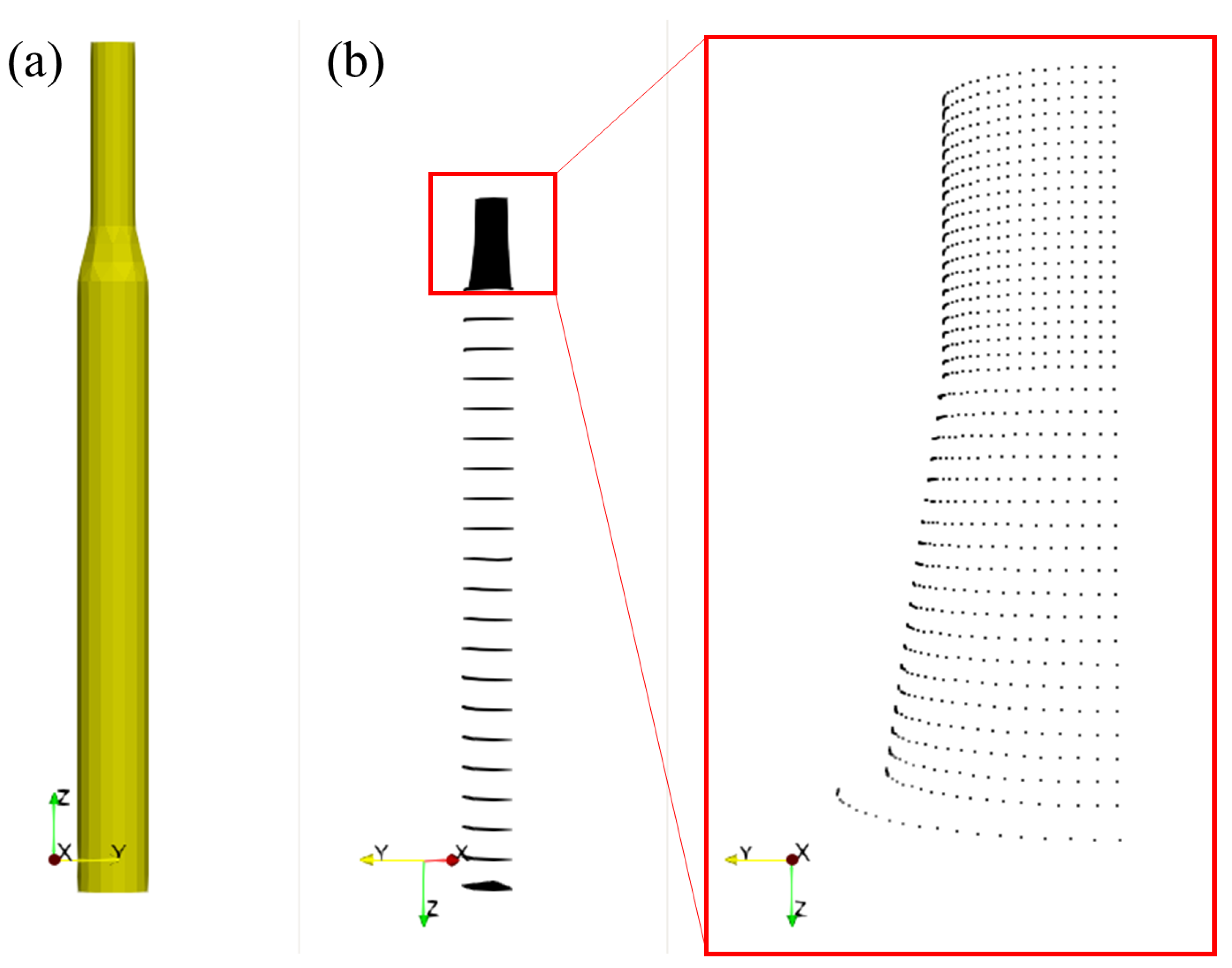
The point system of the Spar’s surface (Figure 4) was created using the open-source code published by Ocean Engineering Committee of Japan Society of Naval Architects and Ocean Engineers (JASNAOE) [35]. The numerical Spar (Figure 4a) follows the experimental model (Figure 2c), but only the underwater part (Figure 4b) has been considered in the calculation. Moreover, just one-fourth of the Spar (Figure 4b) is sufficient for the calculation due to its axisymmetric surface, and the convergence of the mesh system has been confirmed separately. Note that the potential theory only considers the underwater part of the Spar, and because the Spar is axisymmetric, just one-fourth of the Spar is sufficient for the calculation. More importantly, the Spar basically consists of two right circular cylinders, and thus, the essential parameters can be directly calculated, including the moment of inertia around x, y, and z axes assuming that the weights are uniformly distributed, and longitudinal and transverse metacentric heights from the gravity center. The open-source code [34] published by JASNAOE was utilized in the simulation process. Additionally, the gravity center was manually determined following the height of the feeding systems (Table 3 and Table 4). Note that installation heights of the feeding system (above the waterline) are based on the full-scale model (Table 1). The heights of the gravity center are calculated based on the bottom of the Spar’s experimental model. On the other hand, the waves based on the experimental wave periods adopted the linear deep-wave theory.

4. Results and Discussion

4.1. Experimental Results

The Spar’s motions were analyzed based on the recorded videos (Figure 5). Note that installation heights of the feeding system (above the waterline) are based on the full-scale model (Table 1). The peak of the heave motion occurred at approximately 3.6 s and was almost not affected by the installation of the feeding systems given the measurement error. Compared to the heave motion, the pitch was more affected by the existence of the feeding systems. Additionally, there appears to be a little but noticeable correlation between the installation heights of the feeding system and the inclination angle. However, all inclination angles were below 1.2 degrees during the experimental wave periods. Because power generation efficiency only decreases when the inclination angle exceeds 5 degrees [36], the impact of the feeding system on the Spar was essentially negligible in the current installation.

4.2. Numerical Validation

We then validated the numerical results (denoted as ‘Cal.’ in the legend) using the experimental ones (Figure 6). Note that the numerical calculations output the nondimensional motion amplitude [32,33], also known as response amplitude operator (RAO), and thus, the experimental results have been re-calculated to meet the comparable format. The heave RAO is nondimensionalized by incident wave height as η 3 / ζ a and the pitch RAO is nondimensionalized as η 5 L / π ζ a . The peak of the heave motion was numerically estimated at 3.6 s, matching the experimental outcomes, and the calculated heave RAO has been reproduced after tuning the coefficients of the mooring lines. Similarly, the pitch RAO was also successfully reproduced. Although the lack of data prevented a direct comparison of the coefficient values with the mooring forces, the parameterization approach has been widely practiced and readily validated [32,33]. However, particular in this study, this approach partially compensated for the rough estimation in the moment of inertia, and more generally, this approach partially compensated for the potential theory’s assumption that the eddies surrounding the Spar are numerically excluded.
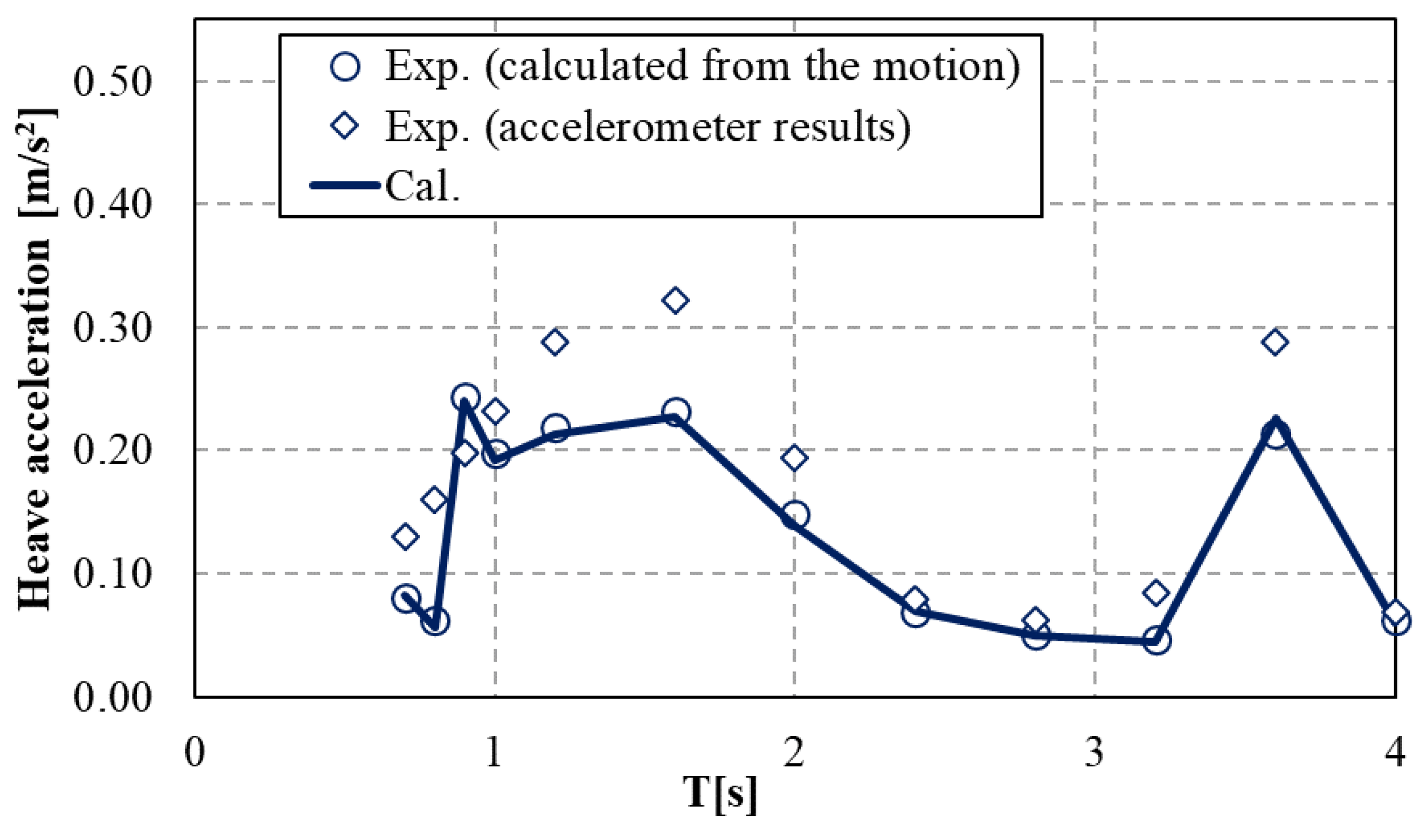
To further examine the effects of the numerical assumption, we double-checked the heave acceleration results using the direct measurements by the accelerometer sensor, calculation results from the observed heave motion (Figure 5a), and numerical calculation results (Figure 7). Generally, two experimental results were consistent and can be mutually verified, and therefore, there was high reliability in the numerical results. However, closer examination of the results revealed the possibility of complex motions in short-period waves, typically less than 2.0 s. Note that the wave periods up to 2.0 s here extended to approximately 14 s in a full-scale scenario, almost covering the typical wave periods encountered in the seas surrounding Japan. As a result, the current framework still possesses uncertainty in directly applying the results to the integration of the Spar with aquaculture facilities in Japan. Further improvements are still encouraged on the experimental and numerical accuracy in short-period waves.

4.3. Numerical Scenarios

The effects of the feeding systems’ installation heights were numerically confirmed on both motions (Figure 8). As a result, the changing tendency were identical with but clearer than the experimental ones. First, no changes were found in the heave RAO, including its natural period (Figure 8a). Therefore, the large variation after installing the feeding system in the experiments is possibly due to the factors beyond the scope of this calculation, such as eddies (Figure 5a). Second, the pitch motion increased to some degree especially in long-period waves (Figure 8b), which is identical to the finding from the experiments but can be theoretically explained in this case. The installation heights of the feeding systems only shifted the gravity center upward. As the gravity center ascended, its corresponding rotation center (including the rotation center of pitch motion under this framework) concurrently ascended, and ultimately accelerated the rotation movement when the rotation center is above the gravity center. Although the coefficients of the mooring lines might vary depending on the center height of gravity, its effects should be insignificant for these scenarios because of the insignificant changes in the gravity center.

4.4. Potential Applications

Note that the above experiments and calculations adopted an assumption that the total weight and displacement of the Spar remained identical before and after the installation of the feeding system. This assumption is achievable by adjusting the ballast water during the real operation, but the following concern is the load capacity of the feeding system. Considering the workload of supplying feed to offshore wind turbines, it is desired to load as much compound feed as possible during the real operation. Given the identical requirement that the feeding system should be placed slightly above the waterline, e.g., at 1.0 m above the waterline because essentially no differences until 12 m existed (Figure 8b), the maximum load capacity of the feeding system has been discussed based on the effects on Spar’s pitch motion because its heave motion was less affected (Figure 8a). Note that the installation heights of the feeding system (above the waterline) in Figure 8 are based on the full-scale model (Table 1).
The discussion included two steps. First, the hydrostatic analysis was conducted using the center height of floatation and gravity (Table 1). Because the hydrostatic restoring force requires a lower center of gravity than floatation (GM > 0), the maximum load capacity (when the gravity center matches that of floatation) was calculated to be approximately 400 tons based on the full-scale model. Second, the pitch RAO was calculated under the current framework, assuming that the wave period-dependent coefficients of the mooring lines remained identical (Figure 9). Note that the weights of the feeding systems are based on the full-scale model, and the increase in pitch RAO was calculated based on the Spar’s pitch motion without feeding systems (Figure 6b). Unsurprisingly, the pitch motion had a significant increase when the center of gravity and floatation was overlapped (i.e., the weight of the feeding system is 400 tons). Although the assumption on the coefficients of the mooring lines affects the value of the pitch RAO, the tendency of the increasing pitch motion remains unchanged. More specifically, the wave period-dependent pitch RAO were generally identical for the feeding systems at 100 and 200 tons. However, the pitch RAO with the feeding system at 300 tons showed an abrupt increase in short-period waves. Compared to the Spar’s pitch motion without feeding systems, the pitch motion increased by 10% to 40% with a 100-tons feeding system and by 35% to 160% with a 200-tons feeding system across different wave periods. From the perspective of motion in the waves, the 100-tons feeding system, which constitutes 3% of the Spar’s displacement loaded into the waterline, is feasible.
Although the present results on the integration of the Spar with the feeding systems appear promising, there are certain challenges that still need to be noticed. First, only the position of the feeding system was variable in this study, and the center of gravity remained fixed during experiments. Actually, the mass of feed constantly changes during aquaculture operations, and the inclination of the wind turbine may cause the feed to roll, potentially affecting the center height of gravity. Second, although the Spar-type is sensitive to the effects of an added feeding system when compared to other types, its size and displacement are continuously increasing. Whether a larger Spar model, possibly with another shape, is suitable for the integration with aquaculture facilities remains unknown. However, with the expected increase in offshore aquaculture production, it is worth considering the critical case when the motion responses of a floating offshore wind turbine are affected by the installation of a feeding system. As a result, further research should further investigate the additional effects of combining aquaculture facilities with the Spar.
A vital area for future research might also include the exploration of the interactions between fish cages and wind turbines in waves. The hydrodynamic interaction between these structures in waves presents a complex scenario that needs thorough numerical and experimental investigation. Future studies could focus on understanding how wave-induced motions affect both the stability and efficiency of wind turbines, as well as the safety and productivity of fish cages. By delving into these aspects, the aim is to develop optimized designs and operational strategies that ensure maximum productivity and minimal operational risks.

5. Conclusions

This study aimed to evaluate the motion responses of a Spar-type floating wind turbine experimentally and numerically in the presence of an attached feeding system. Following the experimental conditions, a 100-tons feeding system was hypothetically mounted on a 2 MW Spar-type floating wind turbine that possessed a displacement capacity of 3500 tons. The experimental results assisted in the validation of the numerical calculation, and the calculation expanded the scenarios for the realistic operation. The main findings have been summarized as follows.
(1)
Compared to the large variations in the experimental results, the numerical results exhibited a clearer changing tendency.
(2)
Both experimental and numerical results indicated that the heave motion was essentially not affected by the installation of the feeding system.
(3)
Although the presence of the feeding system theoretically resulted in an increase in the Spar’s pitch motion, occasional decreases were found in the experiments due possibly to the effects of eddies. However, the overall inclination angle in the experiments did not exceed 1.2 degrees during the experimental wave periods, indicating a negligible impact of the current feeding system on the Spar’s motion.
As a conclusion, the results promote the feasibility of an offshore wind turbine-aquaculture system and encourage the further examination on the additional effects of combining aquaculture facilities with the Spar.

Author Contributions

Conceptualization, Q.L., S.B. and D.K.; methodology, Q.L., D.K. and S.D.; software, S.D. and J.Z.; formal analysis, Q.L., S.B. and S.D.; investigation, Q.L., S.B., S.D. and J.Z.; data curation, Q.L.; writing—original draft preparation, Q.L. and S.B.; writing—review and editing, S.D., J.Z. and D.K.; visualization, Q.L. and S.B.; supervision, D.K.; project administration, D.K.; funding acquisition, D.K. All authors have read and agreed to the published version of the manuscript.

Funding

This work was supported by the JST-Mirai Program Grant Number JPMJMI21C1 through the project “Development of Next Generation Sustainable Aquaculture System”.

Data Availability Statement

All data included in this study are available upon request by contacting the corresponding author.

Conflicts of Interest

The authors declare no conflicts of interest.

Nomenclature

A i j added mass coefficient matrix
B i j damping coefficient matrix
C i j restoring force coefficient matrix
F β α external force acting on six DoF
G M center of gravity
g gravitational acceleration
h water depth
K i j mooring line coefficient
L representative diameter of Spar
M i j inertia matrix
n normal vector
T wave period
T R e a l converted wave period
V velocity vector
x , y , z coordinates
η i six DoF motions
ϕ velocity potential
ζ a incident wave height

References

  1. Zhou, J.; Kitazawa, D.; Yoshida, T.; Fujii, T.; Zhang, J.; Dong, S.; Li, Q. Numerical simulation of dissolved aquaculture waste transport based on water circulation around shellfish and salmon farm sites in Onagawa Bay, Northeast Japan. J. Mar. Sci. Technol. 2020, 26, 812–827. [Google Scholar] [CrossRef]
  2. Naylor, R.; Burke, M. Aquaculture and ocean resources: Raising tigers of the sea. Annu. Rev. Environ. Resour. 2005, 30, 185–218. [Google Scholar] [CrossRef]
  3. Gentry, R.R.; Froehlich, H.E.; Grimm, D.; Kareiva, P.; Parke, M.; Rust, M.; Gaines, S.D.; Halpern, B.S. Mapping the global potential for marine aquaculture. Nat. Ecol. Evol. 2017, 1, 1317–1324. [Google Scholar] [CrossRef] [PubMed]
  4. Thorvaldsen, T.; Salomonsen, C.; Ranum, S.A.; Trædal, P.; Misund, A.; Holmen, I.M. Prepared for the worst? Emergency preparedness in Norwegian fish farming—Status and further improvements. Aquaculture 2023, 577, 739921. [Google Scholar] [CrossRef]
  5. Yu, J.; Yan, T. Analyzing industrialization of deep-sea cage mariculture in China: Review and performance. Rev. Fish. Sci. Aquac. 2023, 31, 483–496. [Google Scholar] [CrossRef]
  6. Fullerton, B.; Swift, M.R.; Boduch, S.; Eroshkin, O.; Rice, G. Design and analysis of an automated feed-buoy for submerged cages. Aquac. Eng. 2004, 32, 95–111. [Google Scholar] [CrossRef]
  7. Tsunoda, T.; Kitazawa, D.; Kinoshita, T.; Ito, S.; Bao, W.; Itakura, H.; Fujino, M. Concept of an offshore aquaculture system with an automated feeding platform. In Proceedings of the ASME 2008 27th International Conference on Offshore Mechanics and Arctic Engineering, Estoril, Portugal, 15–20 June 2008; Volume 6, pp. 527–534. [Google Scholar]
  8. Tang, H.J.; Chiang, W.S.; Nan, F.H. Engineering feasibility assessment of cage aquaculture in offshore wind power generation areas in Taiwan. Sustainability 2022, 14, 11705. [Google Scholar] [CrossRef]
  9. Huang, C.T.; Afero, F.; Hung, C.W.; Chen, B.Y.; Nan, F.H.; Chiang, W.S.; Tang, H.J.; Kang, C.K. Economic feasibility assessment of cage aquaculture in offshore wind power generation areas in Changhua County, Taiwan. Aquaculture 2022, 548, 737611. [Google Scholar] [CrossRef]
  10. Buck, B.H.; Krause, G.; Rosenthal, H. Extensive open ocean aquaculture development within wind farms in Germany: The prospect of offshore co-management and legal constraints. Ocean Coast. Manag. 2004, 47, 95–122. [Google Scholar] [CrossRef]
  11. Li, Q.; Dong, S.; Zhou, J.; Kitazawa, D. An experimental study on the responses of a Spar-type floating structure integrated with aquaculture systems. In Proceedings of the ASME 2023 42nd International Conference on Offshore Mechanics and Arctic Engineering, Melbourne, Australia, 9–14 June 2023; OMAE2023-104637. [Google Scholar]
  12. Nakahara, H.; Shiobara, Y. Fisheries-harmonious offshore wind farm basic concept and some alternative menu. In Proceedings of the Norway-Japan Marine Seminar, Odaiba, Tokyo, Japan, 4 June 2014. [Google Scholar]
  13. Wang, T.Y.; Xu, T.J.; Wang, S.; Dong, G.H.; Yan, L.H. Hydrodynamic analysis of the combined structure of offshore monopile wind turbine foundation and aquaculture cage. Ocean Eng. 2023, 287, 115796. [Google Scholar] [CrossRef]
  14. Buck, B.H.; Krause, G. Integration of aquaculture and renewable energy systems. In Encyclopedia of Sustainability Science and Technology; Meyers, R.A., Ed.; Springer: New York, NY, USA, 2013; pp. 152–173. [Google Scholar]
  15. Zheng, X.Y.; Lei, Y. Stochastic response analysis for a floating offshore wind turbine integrated with a steel fish farming cage. Appl. Sci. 2018, 8, 1229. [Google Scholar] [CrossRef]
  16. Filgueira, J.R. AquaWind: Innovative multi-use prototype combining offshore renewable energy and aquaculture in the Atlantic Basin. In Proceedings of the XVIII Congreso Nacional de Acuicultura (XVIII Spanish National Congress of Aquaculture) Cadiz, Andalusia, Spain, 21–24 November 2022. [Google Scholar]
  17. Zheng, X.; Zheng, H.; Lei, Y.; Li, Y.; Li, W. An offshore floating wind–solar–aquaculture system: Concept design and extreme response in survival conditions. Energies 2020, 13, 604. [Google Scholar] [CrossRef]
  18. Ruzzo, C.; Failla, G.; Arena, F.; Collu, M.; Li, L.; Mariotti, A. Analysis of the coupled dynamics of an offshore floating multi-purpose platform: Part B—Hydro-elastic analysis with flexible support platform. In Proceedings of the ASME 2019 38th International Conference on Offshore Mechanics and Arctic Engineering, Glasgow, Scotland, UK, 9–14 June 2019. OMAE2019-96282. [Google Scholar]
  19. Ruzzo, C.; Muggiasca, S.; Malara, G.; Taruffi, F.; Belloli, M.; Collu, M.; Li, L.; Brizzi, G.; Arena, F. Scaling strategies for multi-purpose floating structures physical modeling: State of art and new perspectives. Appl. Ocean Res. 2021, 108, 102487. [Google Scholar] [CrossRef]
  20. Yang, C.; Yuan, H.; Bai, X.; Hao, Z.; Sun, Y.; Wu, D.; Johanning, L. Numerical investigations on fluid characteristics around the bottom-fixed aquacultural farm. Ocean Eng. 2022, 266, 112689. [Google Scholar] [CrossRef]
  21. Li, N.; Shi, W.; Han, X.; Li, X.; Verma, A.S.; Liu, C. Dynamic analysis of an integrated offshore structure comprising a jacket-supported offshore wind turbine and aquaculture steel cage. Ocean Eng. 2023, 274, 114059. [Google Scholar] [CrossRef]
  22. Zheng, X.Y.; Zheng, H.D.; Lei, Y.; Chen, H. Nonlinear stochastic responses of a newly developed floating wind-solar-aquaculture system. Ocean Eng. 2021, 241, 110055. [Google Scholar] [CrossRef]
  23. Cao, S.; Cheng, Y.; Duan, J.; Fan, X. Experimental investigation on the dynamic response of an innovative semi-submersible floating wind turbine with aquaculture cages. Renew. Energ. 2022, 200, 1393–1415. [Google Scholar] [CrossRef]
  24. Lei, Y.; Li, W.; Zheng, X.Y.; Zheng, H.; Gao, S.; Zhao, S. A floating system integrating a wind turbine with a steel fish farming cage: Experimental validation of the hydrodynamic model. Mar. Struct. 2024, 93, 103525. [Google Scholar] [CrossRef]
  25. Ma, Y.; Li, L.; Ong, M.C.; Jin, J.; Su, B. Dynamic analysis of an offshore fish farm integrated with a floating offshore wind turbine using shared mooring line. In Proceedings of the ASME 2023 42nd International Conference on Ocean, Offshore and Arctic Engineering, Melbourne, Australia, 11–16 June 2023. OMAE2023-101055. [Google Scholar]
  26. Tanaka, K.; Sato, I.; Utsunomiya, T.; Kakuya, H. Validation of dynamic response of a 2-MW hybrid-spar floating wind turbine during typhoon using full-scale field data. Ocean Eng. 2020, 218, 108262. [Google Scholar] [CrossRef]
  27. Ushigami, K. Commercialization started from the ministry of the environment’s floating offshore wind power generation demonstration project. Wind Energy 2016, 40, 258–261. (In Japanese) [Google Scholar]
  28. Ishida, S.; Kokubun, K.; Nimura, T.; Utsunomiya, T.; Sato, I.; Yoshida, S. At-sea experiment of a hybrid spar type offshore wind turbine. In Proceedings of the ASME 2013 33rd International Conference on Offshore Mechanics and Arctic Engineering, Nantes, France, 9–14 June 2013. OMAE2013-10655. [Google Scholar]
  29. Nakai, K.; Hashimoto, N.; Nukada, K. Differences of frequency characteristics of infragravity waves observed along and off Japanese Coasts. J. Jpn. Soc. Civ. Eng. Ser. B3 (Ocean Eng.) 2014, 70, 205–210. (In Japanese) [Google Scholar]
  30. Han, J.; Maeda, T.; Itakura, H.; Kitazawa, D. Experimental study on the motion reduction performance of a small suspension catamaran exploiting an active skyhook control strategy. Ocean Eng. 2023, 281, 114642. [Google Scholar] [CrossRef]
  31. Hermawan, Y.A.; Furukawa, Y. Coupled three-dimensional dynamics model of multi-component mooring line for motion analysis of floating offshore structure. Ocean Eng. 2020, 200, 106928. [Google Scholar] [CrossRef]
  32. Li, Q.; Nihei, Y. Wave drift forces’ calculation on two floating bodies based on the boundary element method—Attempt for improvement of the constant panel method. J. Offshore Mech. Arct. Eng. Trans. ASME 2019, 141, 041801. [Google Scholar] [CrossRef]
  33. New Energy and Industrial Technology Development Organization (NEDO). Project Report of “Development of the Next-Generation Ocean Energy Power Generation Technology Wave Energy Converters with Linear Generators”, 20180000000866; NEDO: Tokyo, Japan, 2019. (In Japanese) [Google Scholar]
  34. Kashiwagi, M.; Takagi, K.; Yasushi, H.; Murai, M.; Yoshida, N. Practice: Hydrodynamics of Floating Bodies; Seizando Shoten Publishing Co., Ltd.: Tokyo, Japan, 2003; ISBN 4-425-71321-4. (In Japanese) [Google Scholar]
  35. Kashiwagi, M. Hydrodynamics of a Floating Body in Waves. Bull. Jpn. Soc. Ind. Appl. Math. 2001, 11, 198–208. (In Japanese) [Google Scholar]
  36. Wang, Q.; Liao, K.; Ma, Q. The influence of tilt angle on the aerodynamic performance of a wind turbine. Appl. Sci. 2020, 10, 5380. [Google Scholar] [CrossRef]
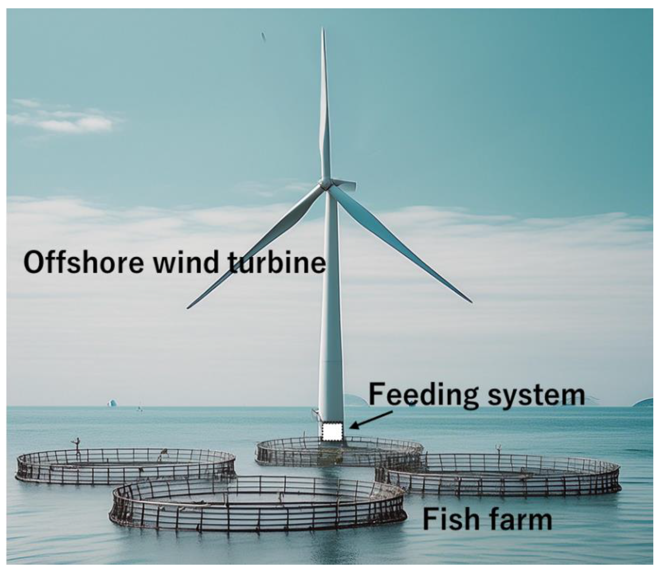
Figure 1. Conceptual figure of an offshore wind turbine-aquaculture system.
Jmse 12 01329 g001
Figure 2. Schematic diagram of the experimental setup with (a) top and (b) side views, and (c) specification of the Spar model and images of feeding systems with three installation heights.
Jmse 12 01329 g002
Figure 3. Example photo of the Spar model and ancillary equipment in the experiments.
Jmse 12 01329 g003
Figure 4. Images of (a) the Spar and (b) point system in the calculation.
Jmse 12 01329 g004
Figure 5. The measured heave (a) and pitch (b) motion of the Spar with different installation heights of the feeding system.
Jmse 12 01329 g005
Figure 6. Comparison of the experimental and numerical results on (a) heave and (b) pitch response amplitude operator (RAO) without the installation of the feeding systems.
Jmse 12 01329 g006
Figure 7. Comparison results of experimental and numerical results on heave acceleration without the installation of the feeding system, using the direct measurements by the accelerometer sensor, calculation results from the observed heave motion (Figure 5a), and numerical calculation results.
Jmse 12 01329 g007
Figure 8. The experimental and numerical results of heave (a) and pitch (b) motion of the Spar with different installation heights of the feeding system.
Jmse 12 01329 g008
Figure 9. The predicted pitch motion (a) and increase in pitch RAO (b) of the Spar with different weights of the feeding systems when being placed at 1.0 m above the waterline, with an assumption that the coefficients of the mooring lines remain identical.
Jmse 12 01329 g009
Table 1. Specifications of the full-scale and scaled model structure [29].
ItemsUnitsFull-Scale ModelScaled Model (1/56)
Spar-type floating structure
Diameter (upper cylindrical pipe)m4.80.09
Diameter (lower cylindrical pipe)m7.80.14
Depth of the cone’s upper endm4.00.07
Depth of the cone’s lower endm10.00.18
Draftm76.01.36
Displacementtons3501.00.02
Freeboardm16.00.29
Center height of floatationm35.00.63
Center height of gravitym28.50.51
Mooring system
Chain mass (in air)kg/m348.50.112
Chain diametermm132.02.370
The length of chain #1 and #3m365.06.540
The length of chain #2m355.06.360
Feeding system
Total masstons or g100 tons561 g
Initial height from the water surfacem1.00.02
Second height from the water surfacem6.00.10
Third height from the water surfacem12.00.20
Table 2. Experimental wave conditions. The wave heights were directly measured and used in the following analysis.
No.123456789101112
Wave period (s)0.70.80.91.01.21.62.02.42.83.23.64.0
Wave height (cm)4.84.15.04.44.95.34.43.32.41.91.12.4
Table 3. The gravity center for the numerical calculation following the experimental setup.
The Height of the Feeding System [m]The Height of the Gravity Center [m]
none0.511
10.534
60.537
120.540
Table 4. The gravity center and metacentric height for the numerical calculation in different feeding system weight.
Feeding System Weight [tons]Feeding System Weight of Model [kg]The Height of the Gravity Center [m]Metacentric Height (GM) [m]
nonenone0.5110.119
1000.570.5340.094
2001.140.5620.068
3001.710.5900.041
4002.290.6180.012
Disclaimer/Publisher’s Note: The statements, opinions and data contained in all publications are solely those of the individual author(s) and contributor(s) and not of MDPI and/or the editor(s). MDPI and/or the editor(s) disclaim responsibility for any injury to people or property resulting from any ideas, methods, instructions or products referred to in the content.