
Experimental and Numerical Investigation on the Motion Responses of a Spar-Type Floating Structure with Aquaculture Feeding Systems


Abstract
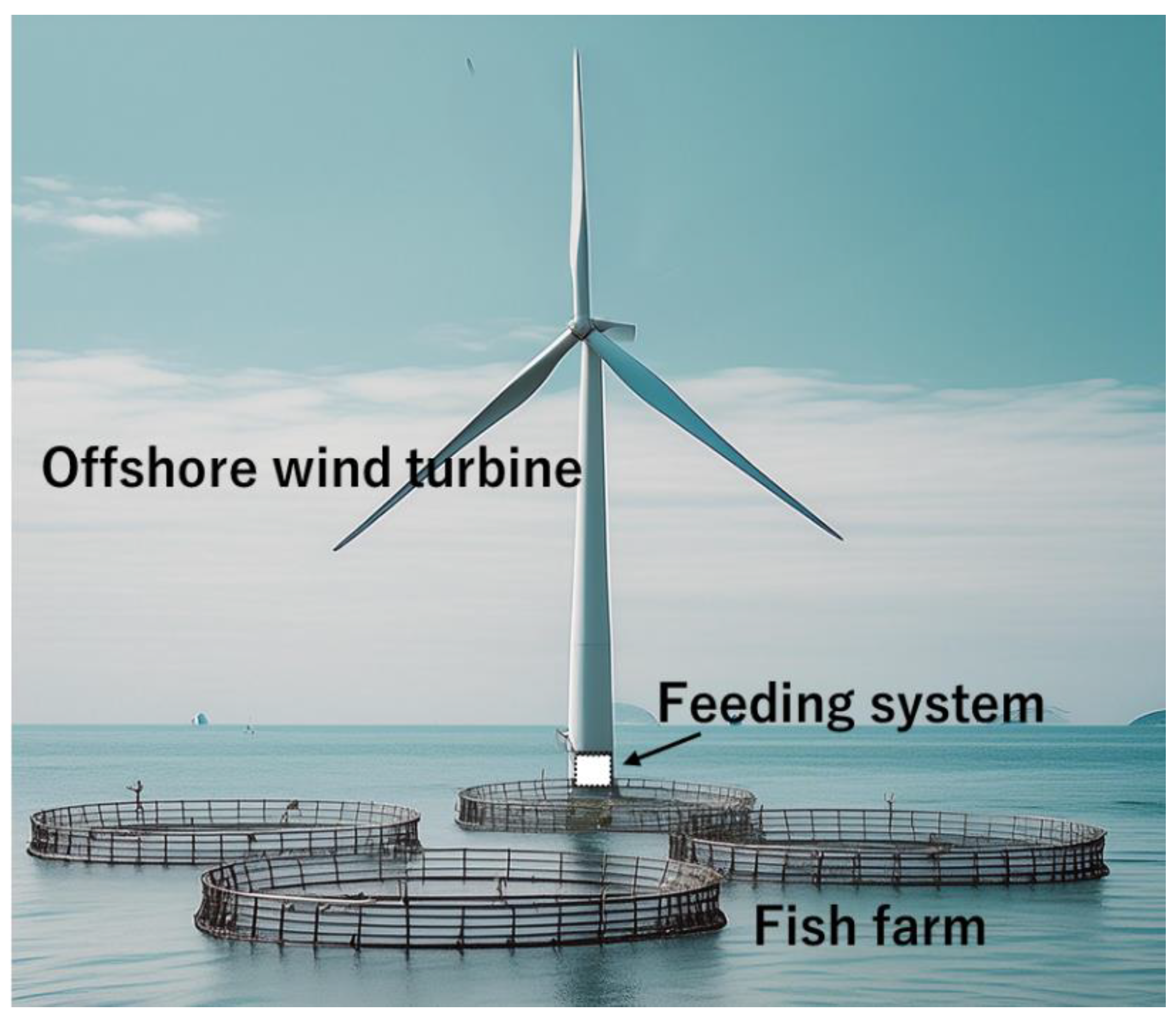
:1. Introduction
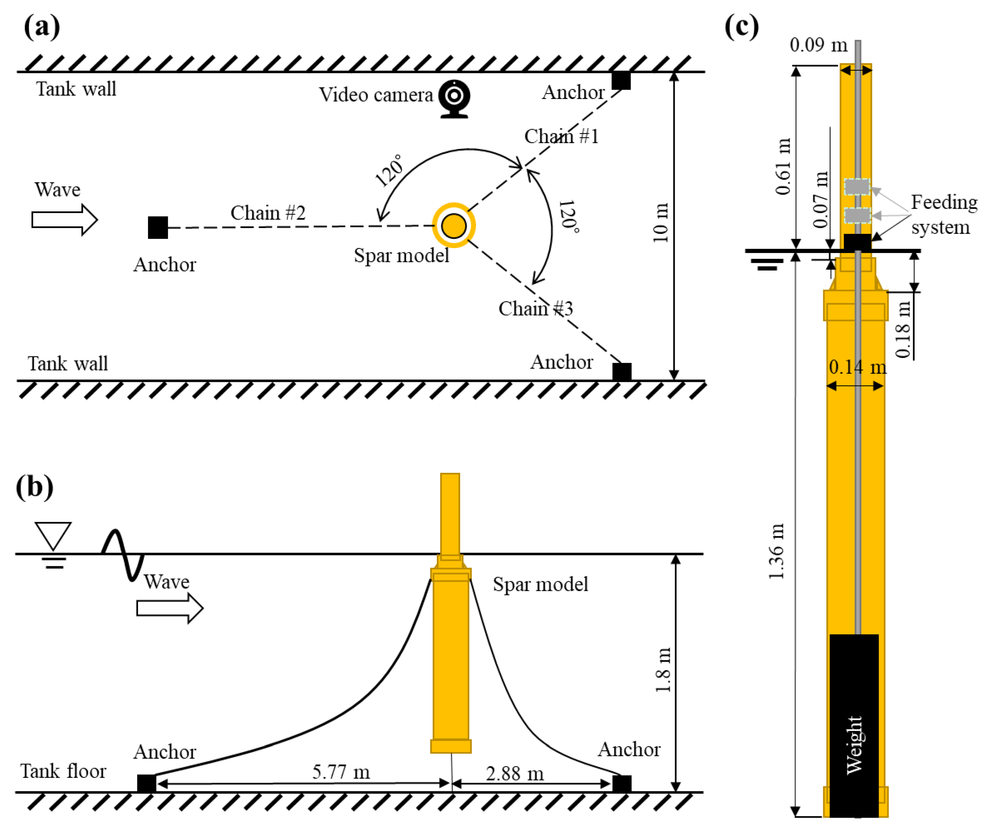
2. Water Tank Experiment
2.1. Model Specifications
2.2. Experimental Conditions
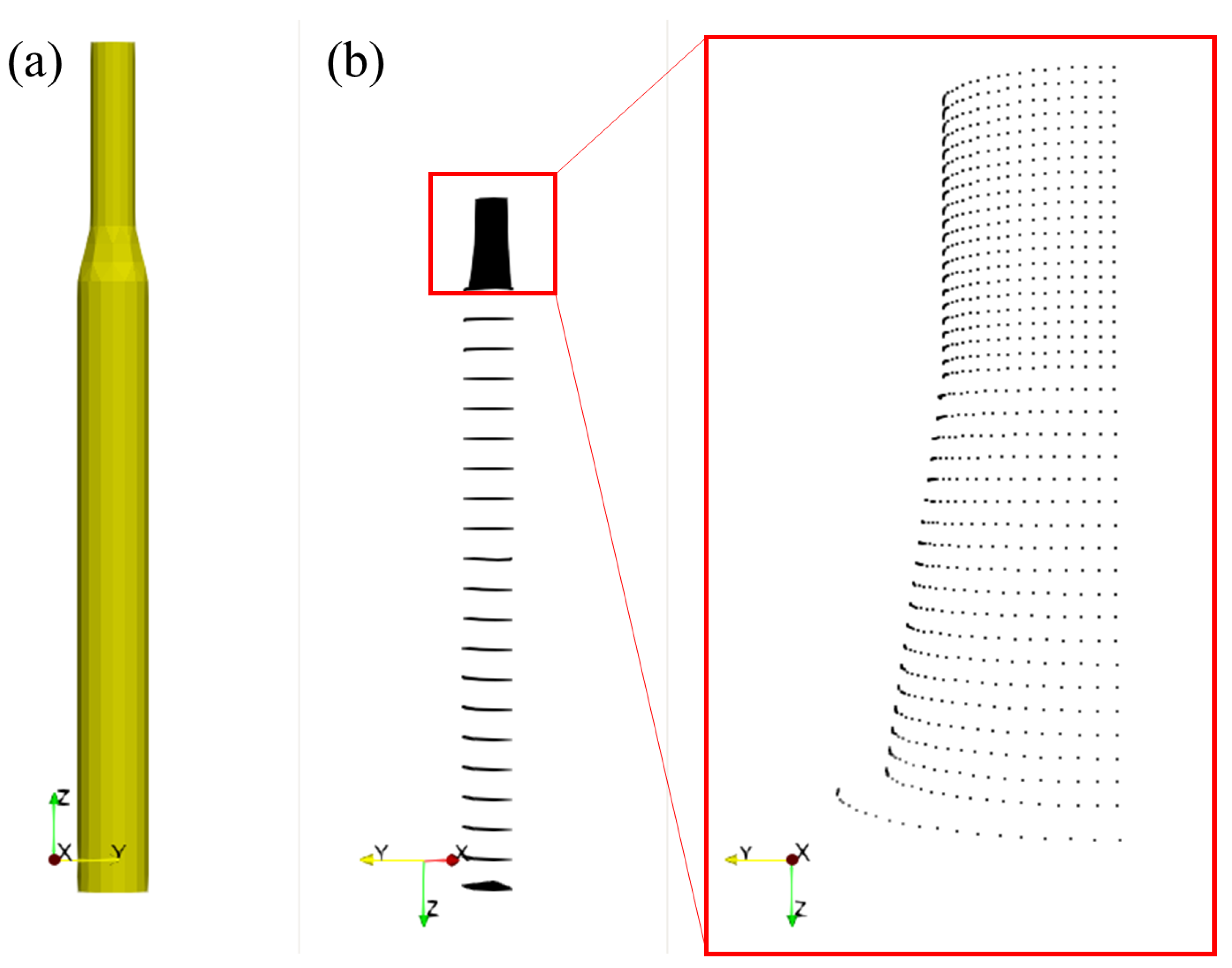
3. Numerical Calculation
3.1. Calculation Equations
3.2. Computational Conditions
4. Results and Discussion
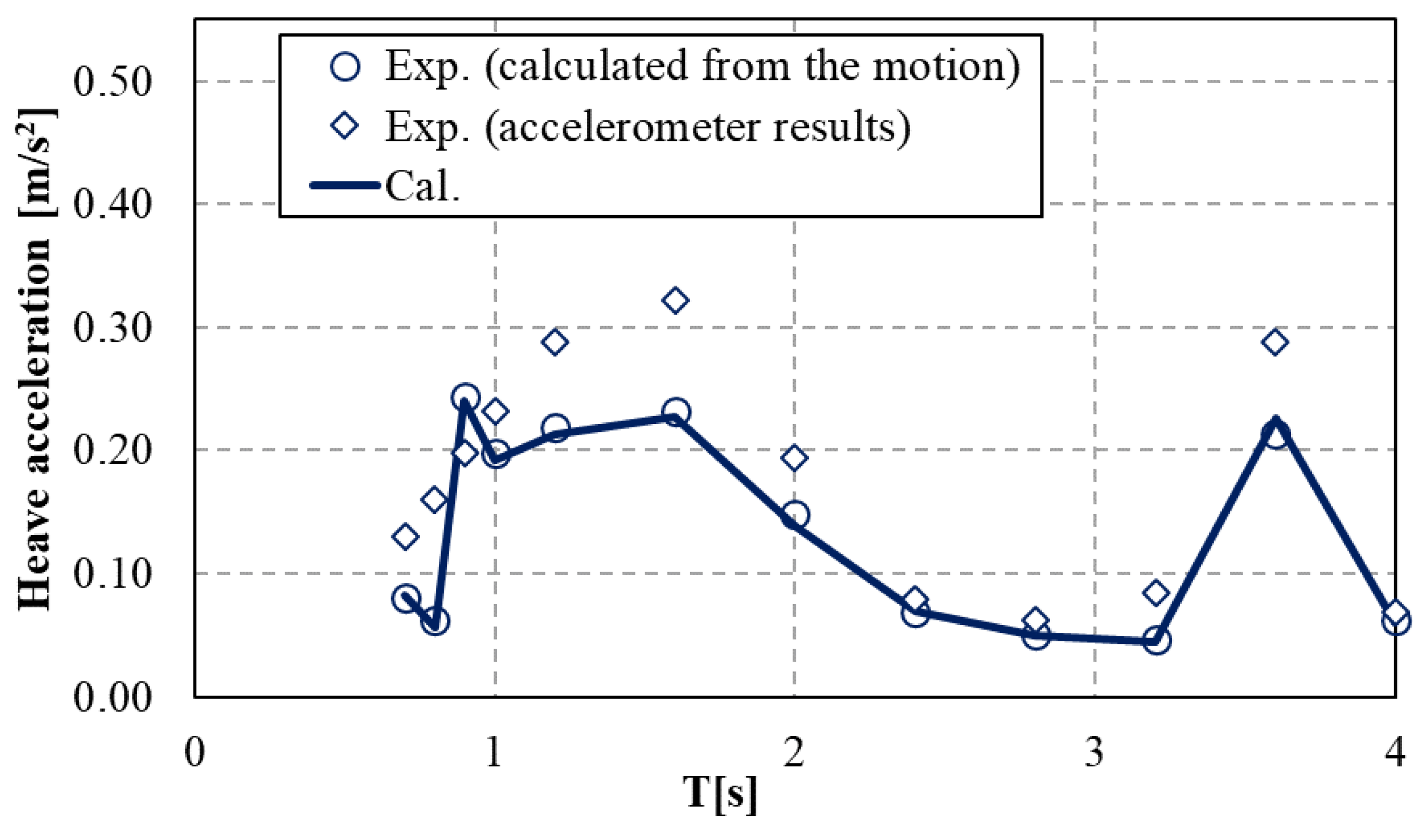
4.1. Experimental Results
4.2. Numerical Validation
4.3. Numerical Scenarios
4.4. Potential Applications
5. Conclusions
- (1)
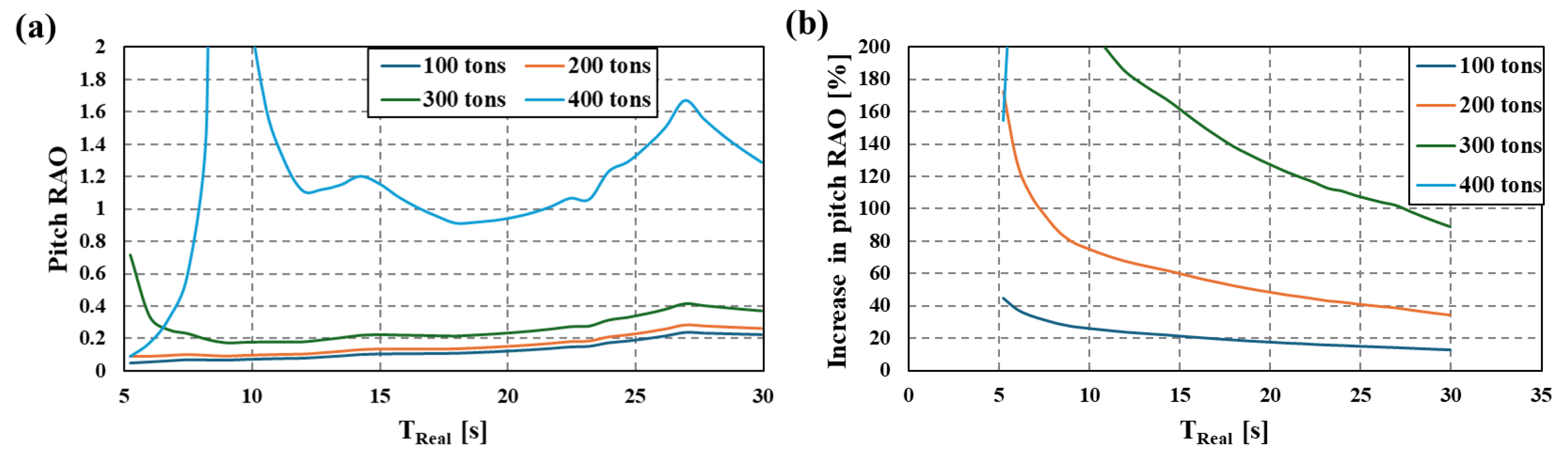
- Compared to the large variations in the experimental results, the numerical results exhibited a clearer changing tendency.
- (2)
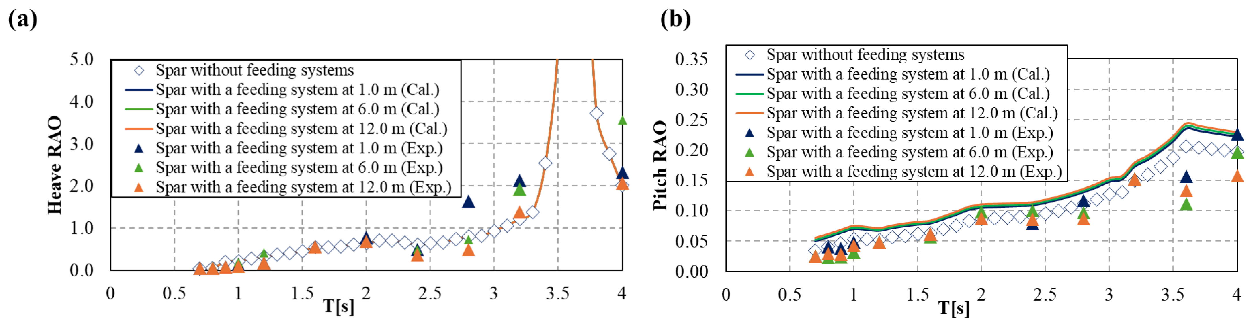
- Both experimental and numerical results indicated that the heave motion was essentially not affected by the installation of the feeding system.
- (3)
- Although the presence of the feeding system theoretically resulted in an increase in the Spar’s pitch motion, occasional decreases were found in the experiments due possibly to the effects of eddies. However, the overall inclination angle in the experiments did not exceed 1.2 degrees during the experimental wave periods, indicating a negligible impact of the current feeding system on the Spar’s motion.
Author Contributions
Funding
Data Availability Statement
Conflicts of Interest
Nomenclature
| added mass coefficient matrix | |
| damping coefficient matrix | |
| restoring force coefficient matrix | |
| external force acting on six DoF | |
| center of gravity | |
| gravitational acceleration | |
| water depth | |
| mooring line coefficient | |
| representative diameter of Spar | |
| inertia matrix | |
| normal vector | |
| wave period | |
| converted wave period | |
| velocity vector | |
| coordinates | |
| six DoF motions | |
| velocity potential | |
| incident wave height |
References
- Zhou, J.; Kitazawa, D.; Yoshida, T.; Fujii, T.; Zhang, J.; Dong, S.; Li, Q. Numerical simulation of dissolved aquaculture waste transport based on water circulation around shellfish and salmon farm sites in Onagawa Bay, Northeast Japan. J. Mar. Sci. Technol. 2020, 26, 812–827. [Google Scholar] [CrossRef]
- Naylor, R.; Burke, M. Aquaculture and ocean resources: Raising tigers of the sea. Annu. Rev. Environ. Resour. 2005, 30, 185–218. [Google Scholar] [CrossRef]
- Gentry, R.R.; Froehlich, H.E.; Grimm, D.; Kareiva, P.; Parke, M.; Rust, M.; Gaines, S.D.; Halpern, B.S. Mapping the global potential for marine aquaculture. Nat. Ecol. Evol. 2017, 1, 1317–1324. [Google Scholar] [CrossRef] [PubMed]
- Thorvaldsen, T.; Salomonsen, C.; Ranum, S.A.; Trædal, P.; Misund, A.; Holmen, I.M. Prepared for the worst? Emergency preparedness in Norwegian fish farming—Status and further improvements. Aquaculture 2023, 577, 739921. [Google Scholar] [CrossRef]
- Yu, J.; Yan, T. Analyzing industrialization of deep-sea cage mariculture in China: Review and performance. Rev. Fish. Sci. Aquac. 2023, 31, 483–496. [Google Scholar] [CrossRef]
- Fullerton, B.; Swift, M.R.; Boduch, S.; Eroshkin, O.; Rice, G. Design and analysis of an automated feed-buoy for submerged cages. Aquac. Eng. 2004, 32, 95–111. [Google Scholar] [CrossRef]
- Tsunoda, T.; Kitazawa, D.; Kinoshita, T.; Ito, S.; Bao, W.; Itakura, H.; Fujino, M. Concept of an offshore aquaculture system with an automated feeding platform. In Proceedings of the ASME 2008 27th International Conference on Offshore Mechanics and Arctic Engineering, Estoril, Portugal, 15–20 June 2008; Volume 6, pp. 527–534. [Google Scholar]
- Tang, H.J.; Chiang, W.S.; Nan, F.H. Engineering feasibility assessment of cage aquaculture in offshore wind power generation areas in Taiwan. Sustainability 2022, 14, 11705. [Google Scholar] [CrossRef]
- Huang, C.T.; Afero, F.; Hung, C.W.; Chen, B.Y.; Nan, F.H.; Chiang, W.S.; Tang, H.J.; Kang, C.K. Economic feasibility assessment of cage aquaculture in offshore wind power generation areas in Changhua County, Taiwan. Aquaculture 2022, 548, 737611. [Google Scholar] [CrossRef]
- Buck, B.H.; Krause, G.; Rosenthal, H. Extensive open ocean aquaculture development within wind farms in Germany: The prospect of offshore co-management and legal constraints. Ocean Coast. Manag. 2004, 47, 95–122. [Google Scholar] [CrossRef]
- Li, Q.; Dong, S.; Zhou, J.; Kitazawa, D. An experimental study on the responses of a Spar-type floating structure integrated with aquaculture systems. In Proceedings of the ASME 2023 42nd International Conference on Offshore Mechanics and Arctic Engineering, Melbourne, Australia, 9–14 June 2023; OMAE2023-104637. [Google Scholar]
- Nakahara, H.; Shiobara, Y. Fisheries-harmonious offshore wind farm basic concept and some alternative menu. In Proceedings of the Norway-Japan Marine Seminar, Odaiba, Tokyo, Japan, 4 June 2014. [Google Scholar]
- Wang, T.Y.; Xu, T.J.; Wang, S.; Dong, G.H.; Yan, L.H. Hydrodynamic analysis of the combined structure of offshore monopile wind turbine foundation and aquaculture cage. Ocean Eng. 2023, 287, 115796. [Google Scholar] [CrossRef]
- Buck, B.H.; Krause, G. Integration of aquaculture and renewable energy systems. In Encyclopedia of Sustainability Science and Technology; Meyers, R.A., Ed.; Springer: New York, NY, USA, 2013; pp. 152–173. [Google Scholar]
- Zheng, X.Y.; Lei, Y. Stochastic response analysis for a floating offshore wind turbine integrated with a steel fish farming cage. Appl. Sci. 2018, 8, 1229. [Google Scholar] [CrossRef]
- Filgueira, J.R. AquaWind: Innovative multi-use prototype combining offshore renewable energy and aquaculture in the Atlantic Basin. In Proceedings of the XVIII Congreso Nacional de Acuicultura (XVIII Spanish National Congress of Aquaculture) Cadiz, Andalusia, Spain, 21–24 November 2022. [Google Scholar]
- Zheng, X.; Zheng, H.; Lei, Y.; Li, Y.; Li, W. An offshore floating wind–solar–aquaculture system: Concept design and extreme response in survival conditions. Energies 2020, 13, 604. [Google Scholar] [CrossRef]
- Ruzzo, C.; Failla, G.; Arena, F.; Collu, M.; Li, L.; Mariotti, A. Analysis of the coupled dynamics of an offshore floating multi-purpose platform: Part B—Hydro-elastic analysis with flexible support platform. In Proceedings of the ASME 2019 38th International Conference on Offshore Mechanics and Arctic Engineering, Glasgow, Scotland, UK, 9–14 June 2019. OMAE2019-96282. [Google Scholar]
- Ruzzo, C.; Muggiasca, S.; Malara, G.; Taruffi, F.; Belloli, M.; Collu, M.; Li, L.; Brizzi, G.; Arena, F. Scaling strategies for multi-purpose floating structures physical modeling: State of art and new perspectives. Appl. Ocean Res. 2021, 108, 102487. [Google Scholar] [CrossRef]
- Yang, C.; Yuan, H.; Bai, X.; Hao, Z.; Sun, Y.; Wu, D.; Johanning, L. Numerical investigations on fluid characteristics around the bottom-fixed aquacultural farm. Ocean Eng. 2022, 266, 112689. [Google Scholar] [CrossRef]
- Li, N.; Shi, W.; Han, X.; Li, X.; Verma, A.S.; Liu, C. Dynamic analysis of an integrated offshore structure comprising a jacket-supported offshore wind turbine and aquaculture steel cage. Ocean Eng. 2023, 274, 114059. [Google Scholar] [CrossRef]
- Zheng, X.Y.; Zheng, H.D.; Lei, Y.; Chen, H. Nonlinear stochastic responses of a newly developed floating wind-solar-aquaculture system. Ocean Eng. 2021, 241, 110055. [Google Scholar] [CrossRef]
- Cao, S.; Cheng, Y.; Duan, J.; Fan, X. Experimental investigation on the dynamic response of an innovative semi-submersible floating wind turbine with aquaculture cages. Renew. Energ. 2022, 200, 1393–1415. [Google Scholar] [CrossRef]
- Lei, Y.; Li, W.; Zheng, X.Y.; Zheng, H.; Gao, S.; Zhao, S. A floating system integrating a wind turbine with a steel fish farming cage: Experimental validation of the hydrodynamic model. Mar. Struct. 2024, 93, 103525. [Google Scholar] [CrossRef]
- Ma, Y.; Li, L.; Ong, M.C.; Jin, J.; Su, B. Dynamic analysis of an offshore fish farm integrated with a floating offshore wind turbine using shared mooring line. In Proceedings of the ASME 2023 42nd International Conference on Ocean, Offshore and Arctic Engineering, Melbourne, Australia, 11–16 June 2023. OMAE2023-101055. [Google Scholar]
- Tanaka, K.; Sato, I.; Utsunomiya, T.; Kakuya, H. Validation of dynamic response of a 2-MW hybrid-spar floating wind turbine during typhoon using full-scale field data. Ocean Eng. 2020, 218, 108262. [Google Scholar] [CrossRef]
- Ushigami, K. Commercialization started from the ministry of the environment’s floating offshore wind power generation demonstration project. Wind Energy 2016, 40, 258–261. (In Japanese) [Google Scholar]
- Ishida, S.; Kokubun, K.; Nimura, T.; Utsunomiya, T.; Sato, I.; Yoshida, S. At-sea experiment of a hybrid spar type offshore wind turbine. In Proceedings of the ASME 2013 33rd International Conference on Offshore Mechanics and Arctic Engineering, Nantes, France, 9–14 June 2013. OMAE2013-10655. [Google Scholar]
- Nakai, K.; Hashimoto, N.; Nukada, K. Differences of frequency characteristics of infragravity waves observed along and off Japanese Coasts. J. Jpn. Soc. Civ. Eng. Ser. B3 (Ocean Eng.) 2014, 70, 205–210. (In Japanese) [Google Scholar]
- Han, J.; Maeda, T.; Itakura, H.; Kitazawa, D. Experimental study on the motion reduction performance of a small suspension catamaran exploiting an active skyhook control strategy. Ocean Eng. 2023, 281, 114642. [Google Scholar] [CrossRef]
- Hermawan, Y.A.; Furukawa, Y. Coupled three-dimensional dynamics model of multi-component mooring line for motion analysis of floating offshore structure. Ocean Eng. 2020, 200, 106928. [Google Scholar] [CrossRef]
- Li, Q.; Nihei, Y. Wave drift forces’ calculation on two floating bodies based on the boundary element method—Attempt for improvement of the constant panel method. J. Offshore Mech. Arct. Eng. Trans. ASME 2019, 141, 041801. [Google Scholar] [CrossRef]
- New Energy and Industrial Technology Development Organization (NEDO). Project Report of “Development of the Next-Generation Ocean Energy Power Generation Technology Wave Energy Converters with Linear Generators”, 20180000000866; NEDO: Tokyo, Japan, 2019. (In Japanese) [Google Scholar]
- Kashiwagi, M.; Takagi, K.; Yasushi, H.; Murai, M.; Yoshida, N. Practice: Hydrodynamics of Floating Bodies; Seizando Shoten Publishing Co., Ltd.: Tokyo, Japan, 2003; ISBN 4-425-71321-4. (In Japanese) [Google Scholar]
- Kashiwagi, M. Hydrodynamics of a Floating Body in Waves. Bull. Jpn. Soc. Ind. Appl. Math. 2001, 11, 198–208. (In Japanese) [Google Scholar]
- Wang, Q.; Liao, K.; Ma, Q. The influence of tilt angle on the aerodynamic performance of a wind turbine. Appl. Sci. 2020, 10, 5380. [Google Scholar] [CrossRef]


| Items | Units | Full-Scale Model | Scaled Model (1/56) |
|---|---|---|---|
| Spar-type floating structure | |||
| Diameter (upper cylindrical pipe) | m | 4.8 | 0.09 |
| Diameter (lower cylindrical pipe) | m | 7.8 | 0.14 |
| Depth of the cone’s upper end | m | 4.0 | 0.07 |
| Depth of the cone’s lower end | m | 10.0 | 0.18 |
| Draft | m | 76.0 | 1.36 |
| Displacement | tons | 3501.0 | 0.02 |
| Freeboard | m | 16.0 | 0.29 |
| Center height of floatation | m | 35.0 | 0.63 |
| Center height of gravity | m | 28.5 | 0.51 |
| Mooring system | |||
| Chain mass (in air) | kg/m | 348.5 | 0.112 |
| Chain diameter | mm | 132.0 | 2.370 |
| The length of chain #1 and #3 | m | 365.0 | 6.540 |
| The length of chain #2 | m | 355.0 | 6.360 |
| Feeding system | |||
| Total mass | tons or g | 100 tons | 561 g |
| Initial height from the water surface | m | 1.0 | 0.02 |
| Second height from the water surface | m | 6.0 | 0.10 |
| Third height from the water surface | m | 12.0 | 0.20 |
| No. | 1 | 2 | 3 | 4 | 5 | 6 | 7 | 8 | 9 | 10 | 11 | 12 |
|---|---|---|---|---|---|---|---|---|---|---|---|---|
| Wave period (s) | 0.7 | 0.8 | 0.9 | 1.0 | 1.2 | 1.6 | 2.0 | 2.4 | 2.8 | 3.2 | 3.6 | 4.0 |
| Wave height (cm) | 4.8 | 4.1 | 5.0 | 4.4 | 4.9 | 5.3 | 4.4 | 3.3 | 2.4 | 1.9 | 1.1 | 2.4 |
| The Height of the Feeding System [m] | The Height of the Gravity Center [m] |
|---|---|
| none | 0.511 |
| 1 | 0.534 |
| 6 | 0.537 |
| 12 | 0.540 |
| Feeding System Weight [tons] | Feeding System Weight of Model [kg] | The Height of the Gravity Center [m] | Metacentric Height (GM) [m] |
|---|---|---|---|
| none | none | 0.511 | 0.119 |
| 100 | 0.57 | 0.534 | 0.094 |
| 200 | 1.14 | 0.562 | 0.068 |
| 300 | 1.71 | 0.590 | 0.041 |
| 400 | 2.29 | 0.618 | 0.012 |
Disclaimer/Publisher’s Note: The statements, opinions and data contained in all publications are solely those of the individual author(s) and contributor(s) and not of MDPI and/or the editor(s). MDPI and/or the editor(s) disclaim responsibility for any injury to people or property resulting from any ideas, methods, instructions or products referred to in the content. |
© 2024 by the authors. Licensee MDPI, Basel, Switzerland. This article is an open access article distributed under the terms and conditions of the Creative Commons Attribution (CC BY) license (https://creativecommons.org/licenses/by/4.0/).
Share and Cite
Li, Q.; Bai, S.; Dong, S.; Zhou, J.; Kitazawa, D. Experimental and Numerical Investigation on the Motion Responses of a Spar-Type Floating Structure with Aquaculture Feeding Systems. J. Mar. Sci. Eng. 2024, 12, 1329. https://doi.org/10.3390/jmse12081329
Li Q, Bai S, Dong S, Zhou J, Kitazawa D. Experimental and Numerical Investigation on the Motion Responses of a Spar-Type Floating Structure with Aquaculture Feeding Systems. Journal of Marine Science and Engineering. 2024; 12(8):1329. https://doi.org/10.3390/jmse12081329
Chicago/Turabian StyleLi, Qiao, Shenyi Bai, Shuchuang Dong, Jinxin Zhou, and Daisuke Kitazawa. 2024. "Experimental and Numerical Investigation on the Motion Responses of a Spar-Type Floating Structure with Aquaculture Feeding Systems" Journal of Marine Science and Engineering 12, no. 8: 1329. https://doi.org/10.3390/jmse12081329