Article

An OOSEM-Based Design Pattern for the Development of AUV Controllers

1
Control, Automation in Production and Improvement of Technology Institute, Hanoi 100000, Vietnam
2
School of Mechanical Engineering, Hanoi University of Science and Technology, Hanoi 100000, Vietnam
*
Authors to whom correspondence should be addressed.
J. Mar. Sci. Eng. 2024, 12(8), 1342; https://doi.org/10.3390/jmse12081342
Submission received: 29 June 2024 / Revised: 28 July 2024 / Accepted: 5 August 2024 / Published: 7 August 2024
(This article belongs to the Section Ocean Engineering)

Abstract

:
This article introduces a new design pattern that provides an optimal solution for the systematic development of AUV controllers. In this study, a hybrid control model is designed on the basis of the OOSEM (Object-Oriented Systems Engineering Method), combined with MDA (Model-Driven Architecture) concepts, real-time UML/SysML (Unified Modeling Language/Systems Modeling Language), and the UKF (unscented Kalman filter) algorithm. This hybrid model enables the implementation of the control elements of autonomous underwater vehicles (AUVs), which are considered HDSs (hybrid dynamic systems), and it can be adapted for reuse for most standard AUV platforms. To achieve this goal, a dynamic AUV model is integrated with the specializations of the OOSEM/MDA, in which an analysis model is clarified via a use-case model definition and then combined with HA (hybrid automata) to precisely define the control requirements. Next, the designed model is tailored via real-time UML/SysML to obtain the core control blocks, which describe the behaviors and structures of the control parts in detail. This design model is then transformed into an implementation model with the assistance of round-trip engineering to conveniently realize a controller for AUVs. Based on this new model, a feasible AUV controller for low-cost, turtle-shaped AUVs is implemented, and it is utilized to perform planar trajectory tracking.

1. Introduction

Water vehicles have been extensively studied and used in defense in the last century. Autonomous underwater vehicles (AUVs) are especially being developed for civilian applications, e.g., maritime monitoring and patrol, disaster and tsunami warnings, and ocean exploration [1,2,3,4].
Control systems for AUVs often face challenges because they must be connected to dynamic AUV models in water environments with complex disturbances, such as nonlinear waves and sea currents. The control system of an AUV can be implemented as a wrapper that associates discrete and continuous blocks with their interactions, called an HDS (hybrid dynamic system), and its control behaviors can be visually modeled by specializing in HA (hybrid automata) [5,6,7]. Study [6] presents a review and comparison of hybrid tools for analyzing the overall behavior of the system, and then suggests the need for a unifying approach to hybrid system design. Traditional control techniques, in combination with soft computational methods, have often been used for unmanned vehicles and robots [8,9]. In [8], the control law is a PID combined with a neural network and Fuzzy control techniques, which are used to solve the quadcopter path tracking problem, while [9] uses SMC (sliding mode control) to handle time-delay systems with Marcovian jumping parameters and nonlinear uncertainty. In study [10], an adaptive controller for an AUV based on PID and anti-windup (AW) compensators is introduced. A modern AW technique is employed to cope with the saturation problem of the actuator. In [11], a new technique called fractional-order PID is used. The cloud-model-based quantum genetic algorithm (CQGA) is employed to tune the coefficients of fractional-order PID controllers. In [12], a hybrid controller based on the combination of an intelligent-PID (i-PID) and PD feedforward controllers is proposed for the trajectory tracking task of an AUV. This new approach shows excellent disturbance rejections, good compensation for the initial tracking error, and keeps the trajectory tracking precision. In [13,14], controllers for AUVs are designed on the basis of other control laws (SMC and MPC), with some modification to the control laws. The performance of these traditional approaches for developing AUV controllers is summarized in Table 1.
A PID controller can be easily adopted for an AUV planar trajectory tracking in low-noise environments, while the backstepping technique shows good stability against high disturbances and can handle model uncertainty. The above-assessed points led us to choose the backstepping technique combined with a PID regulator, which is named the integrator backstepping (IB) method, to model the continuous behavior evolutions of the AUV controllers. In addition, development costs and reusability need to be considered when constructing an application. Reusability plays a vital role in the process of developing different applications for AUVs. To achieve this objective, the UML has been standardized to visually analyze and design different system components in the software industrial field. Furthermore, the SysML (System Modeling Language) [26], which is based on the UML and has been standardized by the OMG (Object Management Group), is utilized to perform different steps (analysis, design, verification, and validation) in realizing industrial systems in different domains. A drawback of UML/SysML is the lack of parts for modeling the internal continuous behavior evolution of the developed systems. Additionally, the OOSEM [27,28,29] was originally based on the MBSE approach, which was standardized by the INCOSE [30,31] for modeling the requirements and designing, analyzing, validating, and verifying the artifacts of developed systems. In [27], the OOSEM is combined with UML to model system needs, requirements, and architectural design, as well as their allocation to hardware, software, databases, and manual procedures. The OOSEM is a development method at the system level that facilitates the combination of systems engineering, OO (object-oriented) software engineering, and applying object-oriented technology in a way that profits from the systems engineering process. In [28], a study was undertaken to explore a mapping between the DBT design processes and the integrated processes defined in the OOSEM and in ISO-15288. The observations from the study were used to update the DBT processes to enable a successful development strategy for submarine design. The OMG also formalized the MDA (Model-Driven Architecture) [32,33] to separate the specifications of systematic operations from their details related to the way of using the capabilities of the system platform. Study [34] investigates a model-driven implementation to realize controllers for autonomous underwater vehicles based on the real-time Unified Modeling Language (UML)/MARTE combined with the specification of hybrid automata. Many industrial applications of the real-time UML and SysML for complicated control systems with the above model-based approaches are shown in [33,34,35,36,37,38,39]. Paper [33] shows statistical findings about the use of UML and model-driven approaches for the design of embedded software in Brazil. Most participants in the survey are clearly aware of the value of the modeling approach and attest to its advantages in productivity and portability. In [35], systems engineering concepts such as development methods, configuration management, functional classification, and design patterns are employed in the development of a fully functional AUV system and its control architecture. In [38], a novel approach based on the MBSE is introduced to model the design verification aspects of embedded systems, along with the system design (structural and behavioral aspects). In addition, the SVOCL (SystemVerilog in Object Constraint Language) is proposed to automate the design verification of embedded systems. In [39], the Model-Driven Architecture approach is used to analyze coordination modes for multiple unmanned underwater vehicles (UUVs) and then create a use-case of formation control and collision avoidance for multi-BlueROV-1.
Hence, the OOSEM and MDA could be specified in combination with the real-time UML [40,41,42] and SysML (denoted as real-time UML/SysML) to describe the specifics of the artifacts of the implemented AUV controller. Based on the above assessments, this study proposes a new design pattern that provides an optimal solution for developing AUV controllers. This study is interested in creating a hybrid model wrapper that combines a dynamic AUV model specified for the OOSEM, with the MDA components consisting of a CIM (Computation Independent Model) representing an analysis model, a PIM (Platform Independent Model) representing a design model, and a PSM (Platform-Specific Model) representing an implementation model, followed by the real-time UML/SysML, an algorithm based on the UKF and HA (hybrid automata), which allows us to deploy a controller for AUVs. On the basis of this hybrid model, a controller for horizontal trajectory tracking dedicated to turtle-shaped AUVs is deployed and tested. This paper includes the following main contributions:
-
A new design pattern is proposed, providing an effective way for the systematic development of AUV controllers and allowing new developers to customize and reuse them for different AUV platforms.
-
A new technique, combining the dynamic model of an AUV with the OOSEM, MDA, UML/SysML, and UKF, is introduced to model and realize the AUV controller, which is considered a hybrid control model. This integration technique conveniently and comprehensively enables the modeling of the AUV control system and facilitates the integration of systems engineering with object-oriented software engineering.

2. Overview of AUV Dynamic Modeling and Control Structure

2.1. Dynamics of Underwater Vehicles for Control

The motional components of underwater vehicles are specified as surge, sway, and heave (position components) and roll, pitch, and yaw (attitude components) by the SNAME [43] (see Table 2).
Based on a model of the general control structure (navigation, guidance, and control) of an underwater vehicle, the AUV kinematics in the navigation frame and the AUV dynamics in the body frame can be described as the first and second Equations in (1), respectively [44]:
η ˙ = J ( η ) v M v ˙ + C ( v ) v + D ( v ) + g ( η ) = τ ( v , u )
where η1 = [x,y,z]T denotes the position; η2 = [ϕ,θ,ψ]T denotes the orientation; η = [η1T,η2T]T; v1 = [u,v,w]T depicts the linear velocities; v2 = [p,q,r]T depicts the angular velocities; ν = [v1T,v2T]T; M, D(ν), and C(ν) describe the inertia, damping, and Coriolis matrices, respectively; g(η) represents the buoyancy forces and gravity; τ(v,u) represents the control forces and torques; and u represents the inputs of the controller.
A discrete state-space model is required to deal with the evolution of the continuous behaviors of the developed AUV in order to estimate the vehicle movements through filters, such as particle filters and extended Kalman filters [45]. The evolution of the continuous states of the AUV controller is developed using (2):
x k = f k 1 ( x k 1 , u k 1 ) + w k 1 y k = h k ( x k ) + v k
where x = η ν ; xk denotes the kth state variables; uk is the control inputs to the system, and yk is its outputs; and wk, vk, and hk denote the supplementary process, measured disturbance, and measurement function, respectively.

2.2. General Architecture of an AUV Controller

An autonomous underwater vehicle often has three sub-systems. The first sub-system, the guidance sub-system, prepares the parameters of the desired trajectory for the AUV controller to reach and follow; the second sub-system, the navigation sub-system, is responsible for predicting the actual AUV states; and the third sub-system, the control sub-system, is mainly responsible for creating the control torques and forces that act on and control the AUV. Each sub-system performs its own individual tasks, yet they must work in coordination for the same purpose, allowing the AUV to perform its missions. Figure 1 shows a BBD (block definition diagram), formatted in the conventions of the SysML, and it describes the interactions of the sub-systems. As previously mentioned, control systems can be seen as a combination of continuous and discrete behaviors, and they are called HDSs (hybrid dynamic systems). Because of the above AUV dynamic models (1)–(2) and the three sub-systems, together with the HDSs’ features, the AUV controllers are thus presumed to be HDSs, of which dynamic models can be implemented using hybrid automata.

3. OOSEM/MDA-Based Development for an AUV Controller

In this section, the MDA concepts in the OOSEM are tailored to realize the control parts of an AUV that, overall, consists of the PIM, CIM, and PSM components. All the modeling elements in the CIM, PIM, and PSM when realizing the AUV controllers are shown in the following sub-sections.

3.1. CIM Realization for AUV Controllers

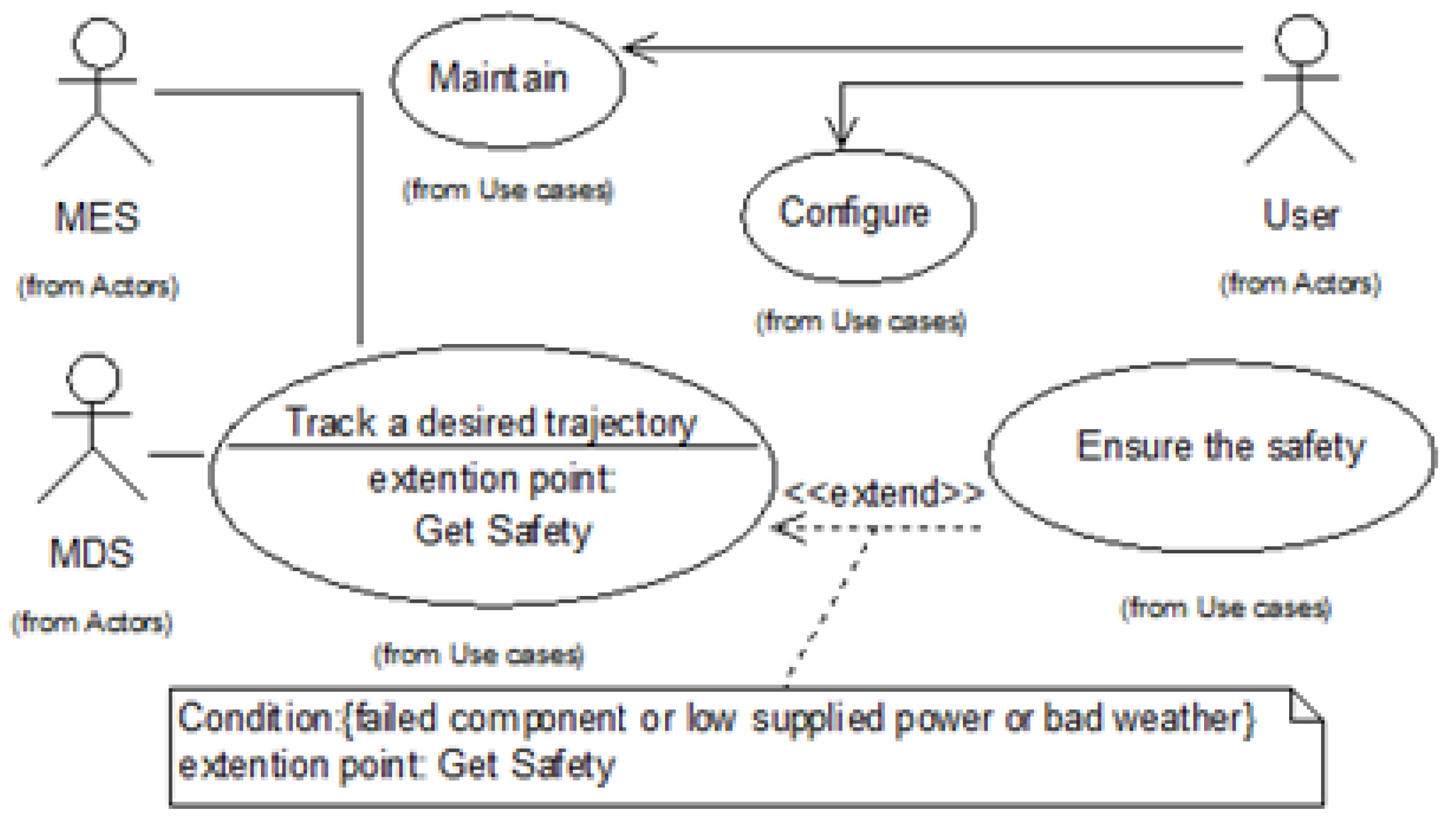
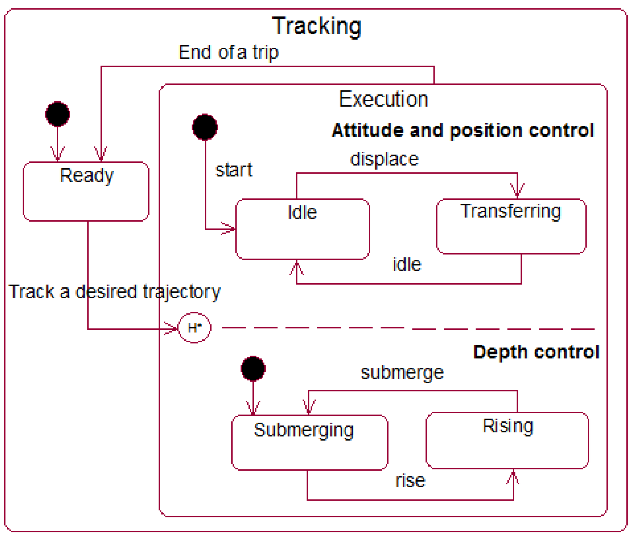
CIM stands for Computation Independent Model and is often called a domain model. It uses vocabulary to represent exactly what the system is expected to do. In the CIM, a use-case model of the real-time UML/SysML, a functional block diagram, in combination with the PID and IB techniques, and HA are defined to model in detail the control requirements. Based on the dynamic model and the control architecture of AUVs, the key use-case model is defined in Figure 2. The control-oriented modes of an AUV are then modeled by using the state machine extracted from the “Track a desired trajectory” use-case. This local state machine is depicted in Figure 3. Here, MES stands for the Marine Environment System, including various disturbances, for example, waves, wind, and ocean current, and MDS stands for Measurement Display System, which includes both the guidance and navigation sub-systems.
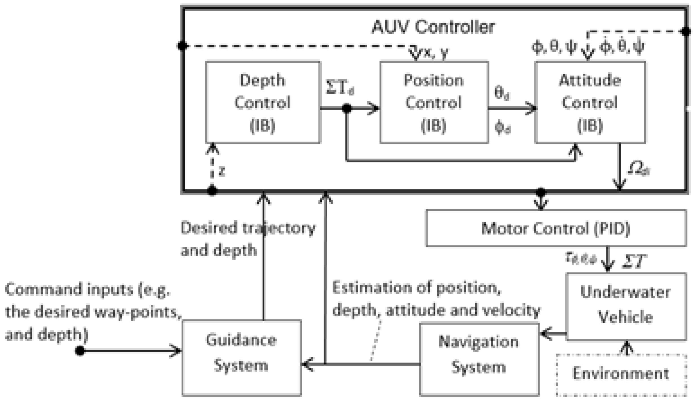
In this paper, a supplemented FBD (functional block diagram) is defined to provide support for modeling the evolutions of the continuous parts of the AUV controllers. It is hard to utilize the real-time UML/SysML version, as it does not have standardized notations to visually model the complex evolutions of internal continuous behaviors combined with control laws, such as the integrator backstepping technique. Thus, a supplemented FBD (Figure 4) is specified to capture the internal continuous evolution of the control parts of the AUV.
Here, depth and desired trajectory are external events providing the desired depth and desired position, respectively, to the reference input of the control blocks. Ωdi, i = 1 , n ¯ are the requisite rotation velocity, which are used to control the motors of the i actuator of the AUV, for example, the rudder, propeller, and sail plan motors. τϕ,θ,Ψ and ΣT represent the output torques and forces allocated to the actuators.
In an analysis model such as the CIM, the HA is applied to globally represent the discrete/continuous models of AUV controllers considered to be HDSs, and it is written as Equation (3):
H A U V = ( Q , X , Σ , A , Inv , F , q o , x co )
where Q is the global state (or situation) of the AUV; qoQ is the unit of Q; X denotes the space of the continuous state for describing the continuous elements of the AUV; Xn; xcoX is the unit of X; and Σ represents external discrete events, which trigger the transformation from the current global state to the target global state. These events are generated from the operating environment, external systems, or users, for example, the MES, MDS, and users described in the use-case diagram (Figure 2). A represents a set of transitions from a situation to another situation, which are often accompanied by internal/external discrete events (σΣ). Inv(q) stands for invariant, which is an application dedicated to verifying if the global state of the system is q. In this case, if the continuous element xc belongs to the global state q, it must be ensured that xcinv(q). F represents the continuous parts followed up in Equations (1) and (2), which depict the whole continuous evolution to a new scenario for the developed AUV. The detailed specifications of the HA and evolution hypotheses for the control parts of AUVs can be seen in [46].

3.2. PIM Realization for AUV Controllers

PIM stands for Platform Independent Model. It has enough independence to be able to map to different platforms. As mentioned above, the IB (integrator backstepping) technique, in combination with the CLFs (candidate Lyapunov functions), is well performed in various AUV control applications. In the PIM, these techniques are used in the position control block, depth control block, and attitude control block (Figure 4), which are continuous elements of the AUV controller. The control algorithm based on the PID is also applied to the motor control block. However, we do not address the details of these control methods because they can be found in a wide range of AUV control applications [10,11,12,13,14,15,16,17,43,44,45,46].
In addition, the discrete state-space model described in (2) is used to estimate the states of the AUV. In this study, the state predictions and estimations can be implemented using the standard navigation filter [46], followed by the UKF algorithm, as shown in Algorithm 1. Here, . ^ represents the estimation; P denotes the covariance matrix of the state-space; and R and Q represent the measured noise and covariance matrices of the process. The state estimation is performed using the following initial conditions: x ^ 0 | 0 = x 0 and P 0 | 0 = 0 12 × 12 .
Algorithm 1. Navigation filter followed up by a UKF filter
 Function UKF-based algorithm
 Step UKF prediction
           Data: x ^ i 1 | i 1 , P i 1 | i 1 , f i 1 ( . )
           Result: x ^ i | i 1 , P i | i 1
      x ^ i | i 1 , P ¯ i | i 1 = U T x ^ i 1 | i 1 , P ¯ i 1 | i 1 , f i 1 . ;
      P i | i 1 = P ¯ i | i 1 + Q i 1 ;
   end
 Step UKF updating
   Data: x ^ i | i 1 , P i | i 1 , h i ( . )
   Result: x ^ i | i , P i | i
    y ^ i | i 1 , S ¯ i , P i x y = U T x ^ i | i 1 , P i | i 1 , h i 1 . ;
    S i = R i + S ¯ i ;
    L i = P i x y S i 1 ;
    e i = y i y ^ i | i 1 ;
    x ^ i | i = x ^ i | i 1 + L i e i ;
    P i | i = P i | i 1 L i S i L i T ;
end
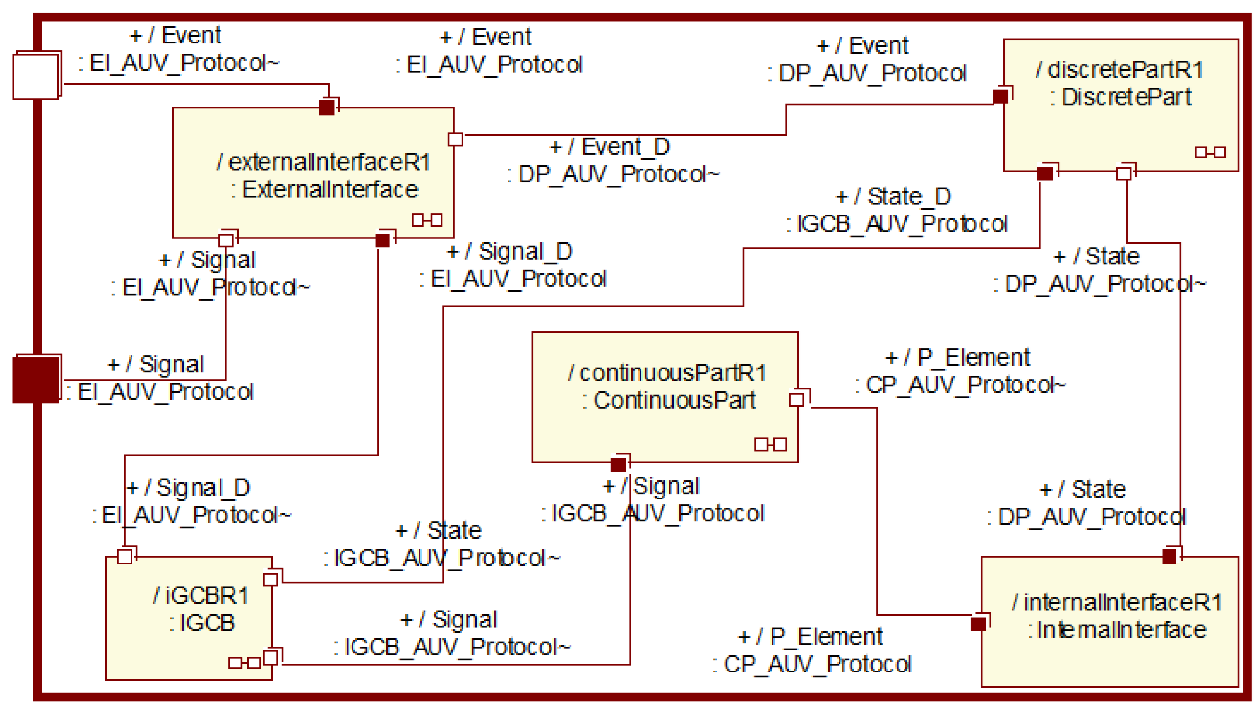
Subsequently, the PIM is conventionally designed to generate a pattern of a real-time capsule, which allows for the visual capture of the control elements in the object collaboration of the real-time UML/SysML. From the CIM components defined above, a set of five capsules of control elements is designed to take part in the HA evolution of the control parts of the developed AUV: a discrete part capsule, a continuous part capsule, an ICGB (Instantaneous Global Continuous Behavior) capsule, an internal interface capsule, and an external interface capsule. Figure 5 shows the design pattern of the various capsules for the AUV following the conventions of the real-time UML/SysML structure and class diagrams.
Here, the discrete part capsule is used to implement transitions A and situations Q in the HA of the developed AUV. It has its own local state machine and runs a process that promotes the exchange of state and events between the discrete part’s capsule and the other capsules through its designed protocol. The IGCB capsule is used to form an instant link among the continuous models. It consists of a set (F) of continuous evolutions corresponding to the situations in the HA. One element of this set (fF) is created from the supplemented FBD (Figure 4). The internal interface capsule is applied to the invariant (Inv) to generate internal discrete events in the continuous–discrete evolution of the HA, which are used in the discrete part’s capsule. The continuous component capsule realizes the continuous evolution occurring in state-space X. This capsule also has its own local state machine and runs a process to maintain interactions with the other capsules. The external interface capsule exchanges continuous signals and discrete events between the designed AUV controller and external elements, such as the MDS, MES, or user system depicted in the use-case diagram (Figure 2).
Figure 6 shows the structures of the control capsules with the protocols defined in Real-Time Design. The CP_AUV_Protocol defines the functions Terminal (void), Ready (void), VerifyInvariant (void), InvariantFalse (void), MemorizeVariable (void), VariableUpdated (void), LastContinuousTerminal (void), Unlock (void), CreateSemaphore (void), Lock (void), Return (void), LastFinishedElement (void), and ActiveElement (void), which could be called the internal interface and continuous parts. The DP_AUV_Protocol, including IndentifiedState (void), Acquire (void), MemorizeEvent (void), and ActivateState (void), is a common protocol for the discrete part, internal interface, and external interface. Similarly, the EI_AUV_Protocol is used by the AUV block, IGCB, and external interface, while the IGCB_AUV_Protocol is dedicated to the AUV block, discrete part, and external interface.
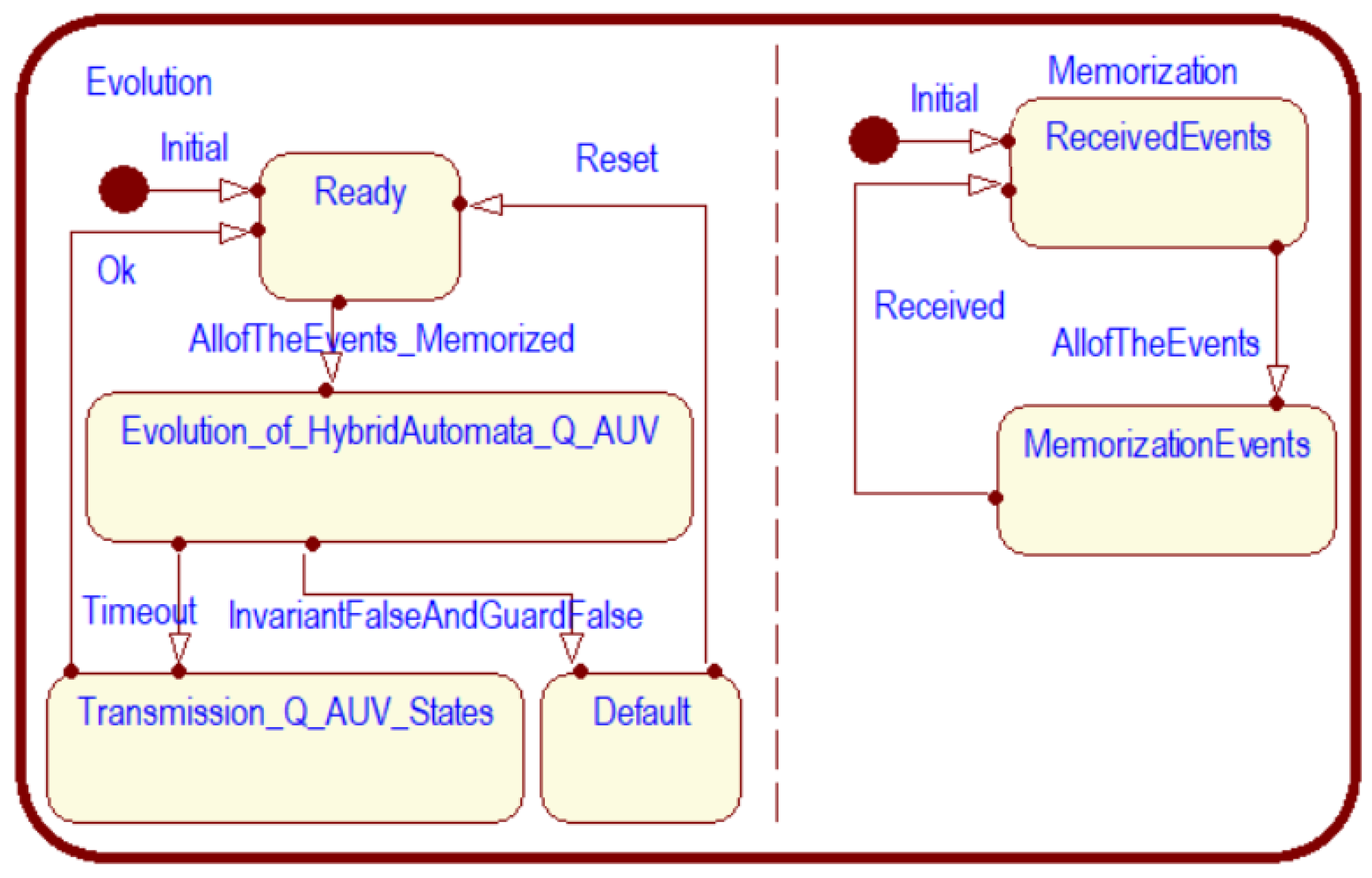
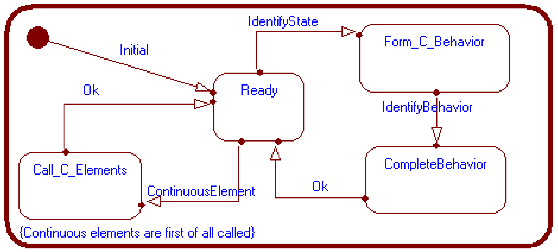
In addition, the discrete part and IGCB capsules have their own local state machines, as shown in Figure 7 and Figure 8, to cooperatively synchronize and validate the realization evolution of the HA for the five main control capsules in this pattern.
As mentioned in Section 1, reusability plays an important role in developing a control system, as it mitigates time, cost, and resources. In the cycle of controller development, reusability can be expanded by the control-capsule-based pattern and its components, e.g., the protocols, ports, connectors, internal structures, and local state machines described in Figure 5, Figure 6, Figure 7 and Figure 8.

3.3. PSM Implementation for an AUV Controller

PSM stands for Platform-Specific Model, and it combines the specification in the PIM with the details depicting how a system is implemented on a particular platform. To realize the AUV controllers, the PIM is transformed into an implementation model. This process can be performed by using various object-oriented software platforms, such as C++, C#, or Java, which support the complete utilization of the model on industrial-specific platforms (EPC, MCU, and PLC). The model ultimately designed by the PIM is first tested using a simulation model. There are various software tools that can perform this simulation, such as IBM Rational Rose Real-time [47] and Open-Modelica [48]. From the simulation results, we can estimate the performance of the designed controller. In the next step, the design artifacts of the model can be optimized before realization. These optimized elements, after simulation, are utilized to adapt the PIM to obtain an updated design model. In the final step, the optimized PIM is converted into a deployment model embedded on available and compatible hardware via IDE tools. Here, round-trip engineering is used to perform the transformations. These techniques are, for example, backward and forward techniques in intermediate programming, with responses of 80% and 20%, respectively, for generated codes and handcrafted codes.

4. Application

On the basis of the hybrid control model proposed above, a controller for tracking a surface trajectory is designed and then deployed on the hardware platform. This controller manipulates a small-scale T-AUV (turtle-shaped autonomous underwater vehicle) to track a desired trajectory on the water surface. The functions of the T-AUV are shown in Table 3.
According to the AUV dynamic models described in Equations (1) and (2), in combination with the assumption that the vertical and lateral motions are negligible because the T-AUV possesses a turtle shape, the dynamic model of the T-AUV can only be concerned with the longitudinal axis line.
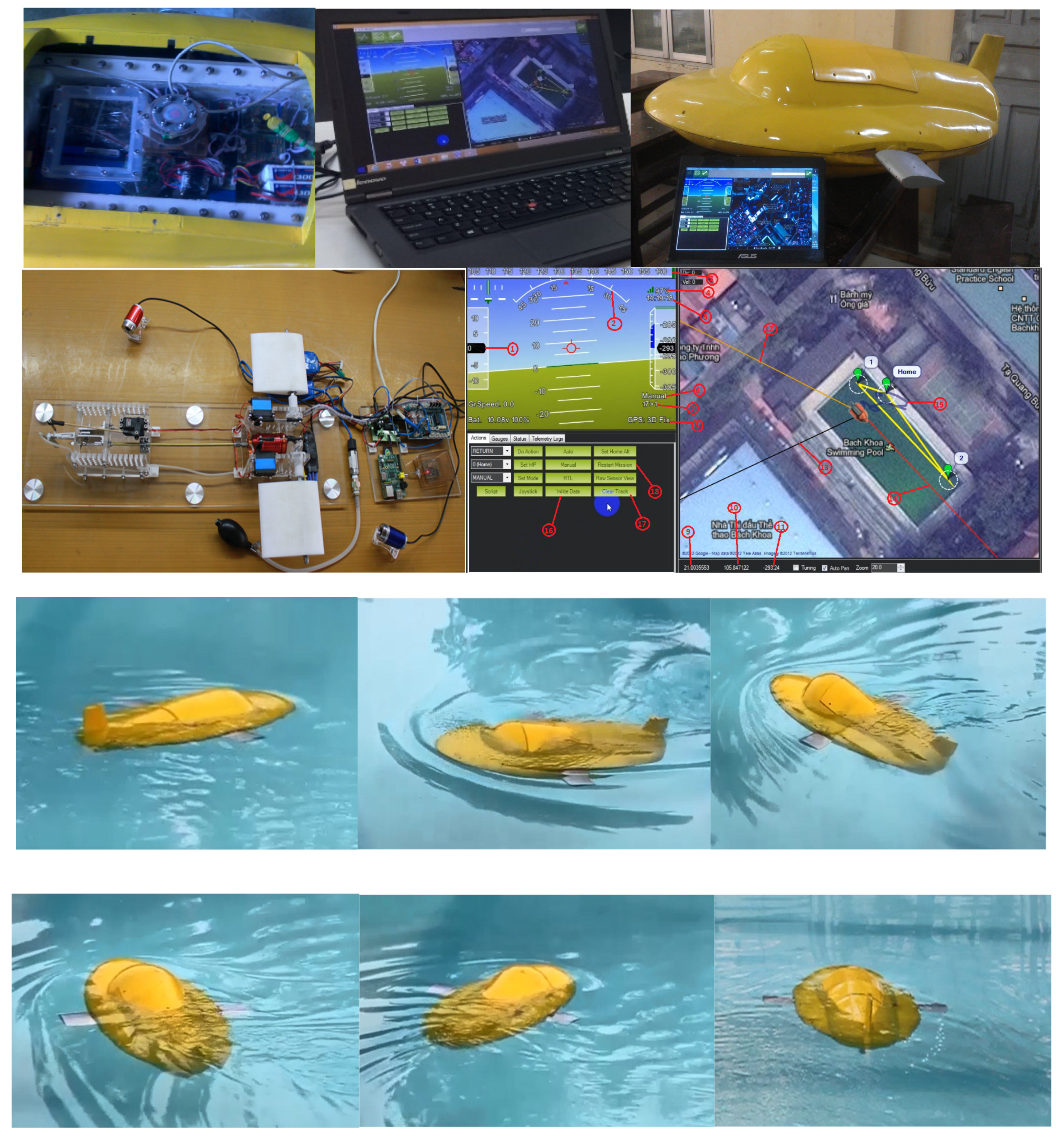
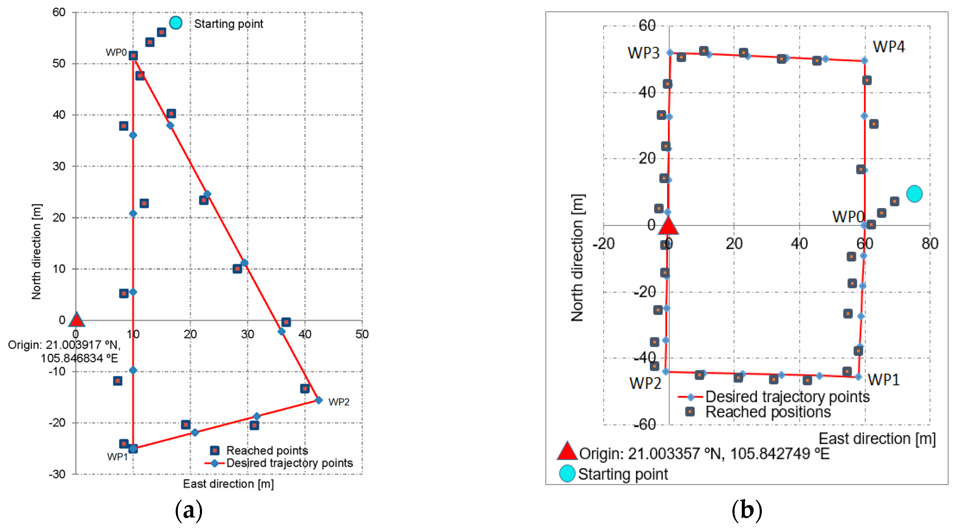
The UKF algorithm (Algorithm 1) was mapped to sensors attached to the T-AUV. These sensors were the GPS Ublox Neo 6M [49] and the IMU MPU6000 [50]. In this study, MCUs, namely, ATMEGA32-U2 and STM32 Cortex-M4 [51], were utilized to embed the control program for the AUV controller. A physical T-AUV was built in order to test the controller, as shown in Figure 9. For a practical test, we predefined different course angles, trajectories, and velocities. The trial results are displayed in Table 4. Figure 10a,b illustrate the trial results, where the T-AUV is controlled to follow the given triangle- and rectangle-shaped trajectories with average velocities of 1.0 and 1.5 m/s, respectively. Table 5 and Table 6 show the trajectory tracking errors based on the RMS (root mean square) calculation, as well as the peak values.
In comparison to the experimental results of the authors’ previous research [44] with PID control and the same AUV model, the new proposed controller decreases the tracking error and time stabilization by 1.5% and 5.5%, respectively. For this new controller, the IB control law and UKF implementations are combined to build depth, attitude, and position control blocks. It is shown that the new proposed controller, accompanied by the IB and UKF techniques, improves the control performance over using a single PID regulator.

5. Conclusions and Future Work

In this paper, a hybrid control model is introduced that effectively supports the deployment of AUV control parts. The proposed model is followed by an OOSEM specialization combined with MDA concepts, real-time UML/SysML, hybrid automata, and the UKF algorithm to accurately deploy AUV controllers. The dynamics and control architecture of the AUV were first used as the inputs of the development lifecycle and integrated with the OOSEM/MDA’s features (CIM, PIM, and PSM). In the CIM, we defined a use-case model, which was then combined with continuous models, such as the FBD (supplemented functional block diagram) and HA, to determine the control requirements in detail. The PIM was equipped with the UKF algorithm to create a design pattern for the control capsules. Next, the designed PIM was transformed into a PSM that deployed the controller with compatible hardware. Finally, a controller for planar trajectory tracking dedicated to a real T-AUV model was implemented and tested with trial cruises. Following the above OOSEM/MDA specialization and real-time UML/SysML, system developers can handle complex systems by utilizing developed model artifacts and traceability in a visual way. Nevertheless, as the real-time UML/SysML version does not have the capability to model complex continuous evolutions combined with control laws in developing control systems, a supplemented FBD could thus be added to the CIM of the developed AUV.
In the future, we plan to develop this proposed framework and application equipped with compatible physical sensors and industrial microcontrollers in order to create a control system that allows the T-AUV to be used for monitoring and patrolling the marine environment of our country, Vietnam.

Author Contributions

Conceptualization, C.D.S., N.V.H. (Ngo Van Hien) and N.V.H. (Ngo Van He); methodology, C.D.S., N.V.H. (Ngo Van Hien), N.V.H. (Ngo Van He) and N.T.K.; software, C.D.S., N.V.H. (Ngo Van Hien) and N.V.H. (Ngo Van He); validation, C.D.S., N.V.H. (Ngo Van Hien) and N.V.H. (Ngo Van He); writing—original draft preparation, C.D.S., N.V.H. (Ngo Van Hien), N.V.H. (Ngo Van He) and N.T.K.; writing—review and editing, C.D.S., N.V.H. (Ngo Van Hien), N.V.H. (Ngo Van He) and N.T.K.; supervision, N.V.H. (Ngo Van Hien) and N.V.H. (Ngo Van He); project administration, N.V.H. (Ngo Van He) All authors have read and agreed to the published version of the manuscript.

Funding

Vietnam Ministry of Education and Training, project ID: B2023-BKA-13.

Data Availability Statement

No new data were created or analyzed in this study. Data sharing is not applicable to this article.

Conflicts of Interest

The authors declare no conflicts of interest.

References

  1. Sivčev, S.; Coleman, J.; Omerdić, E.; Dooly, G.; Toal, D. Underwater manipulators: A review. Ocean Eng. 2018, 163, 431–450. [Google Scholar] [CrossRef]
  2. Petillot, Y.R.; Antonelli, G.; Casalino, G.; Ferreira, F. Underwater Robots: From Remotely Operated Vehicles to Intervention-Autonomous Underwater Vehicles. IEEE Robot. Autom. Mag. 2019, 26, 94–101. [Google Scholar] [CrossRef]
  3. Bao, J.; Li, D.; Qiao, X.; Rauschenbach, T. Integrated navigation for autonomous underwater vehicles in aquaculture: A review. Inf. Process. Agric. 2020, 7, 139–151. [Google Scholar] [CrossRef]
  4. AUVAC. Autonomous Undersea Vehicles Applications Center. 2022. Available online: https://auvac.org/ (accessed on 1 February 2022).
  5. Henzinger, T.A.; Kopke, P.W.; Puri, A.; Varaiya, P. What’s Decidable about Hybrid Automata? J. Comput. Syst. Sci. 1998, 57, 94–124. [Google Scholar] [CrossRef]
  6. Carloni, L.P.; Passerone, R.; Pinto, A.; Sangiovanni-Vincentelli, A.L. Languages and Tools for Hybrid Systems Design. Found. Trends Electron. Des. Autom. 2006, 1, 1–193. [Google Scholar] [CrossRef]
  7. Fishwick, P.A. Handbook of Dynamic System Modeling; Taylor & Francis Group: Abingdon, UK, 2007. [Google Scholar] [CrossRef]
  8. EL Hamidi, K.; Mjahed, M.; El Kari, A.; Ayad, H. Neural Network and Fuzzy-logic-based Self-tuning PID Control for Quadcopter Path Tracking. Stud. Inform. Control 2019, 28, 401–412. [Google Scholar] [CrossRef]
  9. Karimi, H.R. A sliding mode approach to H∞ synchronization of master–slave time-delay systems with Markovian jumping parameters and nonlinear uncertainties. J. Frankl. Inst. 2012, 349, 1480–1496. [Google Scholar] [CrossRef]
  10. Sarhadi, P.; Noei, A.R.; Khosravi, A. Model reference adaptive PID control with anti-windup compensator for an autonomous underwater vehicle. Robot. Auton. Syst. 2016, 83, 87–93. [Google Scholar] [CrossRef]
  11. Wan, J.; He, B.; Wang, D.; Yan, T.; Shen, Y. Fractional-Order PID Motion Control for AUV Using Cloud-Model-Based Quantum Genetic Algorithm. IEEE Access 2019, 7, 124828–124843. [Google Scholar] [CrossRef]
  12. Bingul, Z.; Gul, K. Intelligent-PID with PD Feedforward Trajectory Tracking Control of an Autonomous Underwater Vehicle. Machines 2023, 11, 300. [Google Scholar] [CrossRef]
  13. Yan, Z.; Yang, Z.; Zhang, J.; Zhou, J.; Jiang, A.; Du, X. Trajectory Tracking Control of UUV Based on Backstepping Sliding Mode with Fuzzy Switching Gain in Diving Plane. IEEE Access 2019, 7, 166788–166795. [Google Scholar] [CrossRef]
  14. Bao, H.; Zhu, H. Modeling and Trajectory Tracking Model Predictive Control Novel Method of AUV Based on CFD Data. Sensors 2022, 22, 4234. [Google Scholar] [CrossRef] [PubMed]
  15. Guerrero, J.; Torres, J.; Creuze, V.; Chemori, A.; Campos, E. Saturation based nonlinear PID control for underwater vehicles: Design, stability analysis and experiments. Mechatronics 2019, 61, 96–105. [Google Scholar] [CrossRef]
  16. Liu, L.; Zhang, L.; Pan, G.; Zhang, S. Robust yaw control of autonomous underwater vehicle based on fractional-order PID controller. Ocean Eng. 2022, 257, 111493. [Google Scholar] [CrossRef]
  17. Alaeddini, A.; Morgansen, K.A.; Mesbahi, M. Augmented state feedback for improving observability of linear systems with nonlinear measurements. Syst. Control Lett. 2019, 133, 104520. [Google Scholar] [CrossRef]
  18. Makdah, A.A.R.A.; Daher, N.; Asmar, D.; Shammas, E. Three-dimensional trajectory tracking of a hybrid autonomous underwater vehicle in the presence of underwater current. Ocean Eng. 2019, 185, 115–132. [Google Scholar] [CrossRef]
  19. Lei, M. Nonlinear diving stability and control for an AUV via singular perturbation. Ocean Eng. 2020, 197, 106824. [Google Scholar] [CrossRef]
  20. Khalaji, A.K.; Tourajizadeh, H. Nonlinear Lyapounov based control of an underwater vehicle in presence of uncertainties and obstacles. Ocean Eng. 2020, 198, 106998. [Google Scholar] [CrossRef]
  21. Liu, J.; Zhao, M.; Qiao, L. Adaptive barrier Lyapunov function-based obstacle avoidance control for an autonomous underwater vehicle with multiple static and moving obstacles. Ocean Eng. 2022, 243, 110303. [Google Scholar] [CrossRef]
  22. Cho, G.R.; Park, D.-G.; Kang, H.; Lee, M.-J.; Li, J.-H. Horizontal Trajectory Tracking of Underactuated AUV using Backstepping Approach. IFAC-PapersOnLine 2019, 52, 174–179. [Google Scholar] [CrossRef]
  23. Du, P.; Yang, W.; Wang, Y.; Hu, R.; Chen, Y.; Huang, S. A novel adaptive backstepping sliding mode control for a lightweight autonomous underwater vehicle with input saturation. Ocean Eng. 2022, 263, 112362. [Google Scholar] [CrossRef]
  24. Yan, Z.; Wang, M.; Xu, J. Robust adaptive sliding mode control of underactuated autonomous underwater vehicles with uncertain dynamics. Ocean Eng. 2019, 173, 802–809. [Google Scholar] [CrossRef]
  25. Su, B.; Wang, H.-B.; Wang, Y. Dynamic event-triggered formation control for AUVs with fixed-time integral sliding mode disturbance observer. Ocean Eng. 2021, 240, 109893. [Google Scholar] [CrossRef]
  26. OMG. SysML Specifications Version 1.6: OMG Formal. 2019. Available online: https://www.omg.org/spec/SysML/ (accessed on 1 August 2024).
  27. Lykins, H.; Friedenthal, S.; Meilich, A. 4.4.4 Adapting UML for an Object Oriented Systems Engineering Method (OOSEM). INCOSE Int. Symp. 2000, 10, 490–497. [Google Scholar] [CrossRef]
  28. Pearce, P.; Hause, M.C. ISO-15288, OOSEM and Model-Based Submarine Design. In Proceedings of the 6th Asia Pacific Conference on Systems Engineering, Deep Blue Tech, Brisbane, Australia, July 2012. [Google Scholar]
  29. INCOSE. Object-Oriented SE Method. 2020. Available online: https://www.incose.org/incose-member-resources/working-groups/transformational/object-oriented-se-method (accessed on 1 August 2024).
  30. INCOSE. Systems Engineering Vision 2025; INCOSE: San Diego, CA, USA, 2014; pp. 2111–2222. [Google Scholar]
  31. International Council on Systems Engineering (INCOSE). Available online: https://www.incose.org/ (accessed on 25 June 2012).
  32. OMG. Model Driven Architecture (MDA): Guide Revision 2.0 of MDA Guide Version 1.0.1 (12 June 2003). OMG Document ormsc/2014-06-01. 2014. Available online: http://www.omg.org/cgi-bin/doc?ormsc/14-06-01 (accessed on 1 June 2014).
  33. Agner, L.T.W.; Soares, I.W.; Stadzisz, P.C.; Simão, J.M. A Brazilian survey on UML and model-driven practices for embedded software development. J. Syst. Softw. 2013, 86, 997–1005. [Google Scholar] [CrossRef]
  34. Rashid, M.; Anwar, M.W.; Khan, A.M. Toward the tools selection in model based system engineering for embedded systems—A systematic literature review. J. Syst. Softw. 2015, 106, 150–163. [Google Scholar] [CrossRef]
  35. Freire, L.O.; Oliveira, L.M.; Vale, R.T.; Medeiros, M.; Diana, R.E.; Lopes, R.M.; Pellini, E.L.; de Barros, E.A. Development of an AUV control architecture based on systems engineering concepts. Ocean Eng. 2018, 151, 157–169. [Google Scholar] [CrossRef]
  36. Van Hien, N.; Van He, N.; Diem, P.G. A model-driven implementation to realize controllers for Autonomous Underwater Vehicles. Appl. Ocean Res. 2018, 78, 307–319. [Google Scholar] [CrossRef]
  37. Soriano, T.; Hien, N.; Tuan, K.; Anh, T. An object-unified approach to develop controllers for autonomous underwater vehicles. Mechatronics 2016, 35, 54–70. [Google Scholar] [CrossRef]
  38. Anwar, M.W.; Rashid, M.; Azam, F.; Kashif, M. Model-based design verification for embedded systems through SVOCL: An OCL extension for SystemVerilog. Des. Autom. Embed. Syst. 2017, 21, 1–36. [Google Scholar] [CrossRef]
  39. Soriano, T.; Pham, H.A.; Ngo, V.H. Analysis of coordination modes for multi-UUV based on Model Driven Architecture. In Proceedings of the 12th France-Japan and 10th Europe-Asia Congress on Mechatronics, Tsu, Japan, 10–12 September 2018; IEEE: Piscataway, NJ, USA. [Google Scholar] [CrossRef]
  40. OMG. UML Profile for MARTE: UML for Model-Driven Development of Real Time and Embedded Systems (RTES). OMG formal/19-04-02. 2019. Available online: https://www.omg.org/spec/MARTE/ (accessed on 2 April 2019).
  41. Selić, B.; Gérard, S. Modeling and Analysis of Real-Time and Embedded Systems with UML and MARTE; Elsevier: Amsterdam, The Netherlands, 2014. [Google Scholar]
  42. Selic, B. Using UML for Modeling Complex Real-Time Systems; Lecture Notes in Computer Science; Springer: Berlin/Heidelberg, Germany, 1998; pp. 250–260. [Google Scholar] [CrossRef]
  43. SNAME. Nomenclature for Treating the Motion of a Submerged Body through a Fluid; SNAME: New York, NY, USA, 1950. [Google Scholar]
  44. Fossen, T.I. Handbook of Marine Craft Hydrodynamics and Motion Control, 2nd ed.; John Wiley & Sons: Chichester, UK, 2021. [Google Scholar]
  45. Allotta, B.; Caiti, A.; Costanzi, R.; Fanelli, F.; Fenucci, D.; Meli, E.; Ridolfi, A. A new AUV navigation system exploiting unscented Kalman filter. Ocean Eng. 2016, 113, 121–132. [Google Scholar] [CrossRef]
  46. Hien, N.V.; He, N.V.; Truong, V.T.; Diem, P.G. Using the Real-Time Unified Modeling Language to Implement an AUV Controller; Research Project Report, Funded by State of Vietnam, KC03.TN05/11-15; Hanoi University of Science and Technology: Hanoi, Vietnam, 2013. [Google Scholar]
  47. IBM. IBM Rational’s Methodology, Software, Online Documentation and Training Kits. 2022. Available online: https://www.ibm.com/academic/home (accessed on 1 April 2022).
  48. OpenModelica. OpenModelica Software, Version 1.18. 2022. Available online: https://www.openmodelica.org/ (accessed on 1 February 2022).
  49. u-blox. Product Selector. 2022. Available online: https://www.u-blox.com/en/product-search (accessed on 1 January 2022).
  50. InvenSense. Sensor System on Chip. 2022. Available online: http://www.invensense.com/ (accessed on 1 January 2022).
  51. Arduino Reference. Available online: https://www.arduino.cc/ (accessed on 1 March 2022).
Figure 1. A block definition diagram realized in SysML to represent the above-mentioned three AUV sub-systems.
Jmse 12 01342 g001
Figure 2. The main use-case model capturing the core requirements of an AUV controller.
Jmse 12 01342 g002
Figure 3. The state machine of the use-case “Track a desired trajectory”.
Jmse 12 01342 g003
Figure 4. A supplemented FBD for capturing the internal continuous evolution of the control parts of an AUV.
Jmse 12 01342 g004
Figure 5. A design pattern depicting control capsules for the developed AUV.
Jmse 12 01342 g005
Figure 6. Structures of control capsules for the developed AUV.
Jmse 12 01342 g006
Figure 7. The local state machine in the discrete part capsule in HA evolution.
Jmse 12 01342 g007
Figure 8. The local state machine in the IGCB capsule for HA evolution.
Jmse 12 01342 g008
Figure 9. T-AUV real model and trial cruises.
Jmse 12 01342 g009
Figure 10. T-AUV approached and followed the triangle- (a) and rectangle-shaped (b) trajectories.
Jmse 12 01342 g010
Table 1. Assessments of the main control techniques used for AUV applications.
Used Control
Techniques
Assessment of the Performance of AUVs for Control Applications
Control TaskStabilityComments
Proportional integral derivative (PID) controller [15,16]For AUV trajectory trackingNot very stable against disturbances or nonlinear systemsEasy to design; response time tapers off with stability; sensitive to noises
Linear quadratic regulator (LQR) [17,18]For AUV heading control and trajectory trackingAverage stability against disturbancesState and noise need to be estimated; better for linear models
Lyapunov stability [19,20,21]For AUV heading controlNot very stable in the surrounding area of the desired waypointsFor linear and nonlinear systems; expert knowledge is required to find Lyapunov functions
Backstepping technique [22,23]For AUV heading control and trajectory trackingStable against high disturbancesFor linear and nonlinear systems; can deal with uncertainty models
Sliding mode control [24,25]For AUV heading control and trajectory trackingAverage stability against disturbancesFor linear and nonlinear systems; chattering effect; no finite time convergence
Table 2. Symbols of SNAME for modeling the motions of an underwater vehicle.
DOFMotionsForces/MomentsLinear/Angular VelocitiesPosition/Euler Angles
1SurgeXux
2SwayYvy
3HeaveZwz
4RollKpϕ
5PitchMqθ
6YawNrψ
Table 3. Key specifications of the T-AUV.
SpecificationsValue
L × W × H(1.26 × 0.61 × 0.40) m
Operating time20 min
Dry weight21.20 kg
2 × Li-Po battery22.2 V, 20,000 mAh
Max. capacity324 W
Max. submerged depth1.20 m
Max. radius of operation450 m
Max. submerging or rising speed0.30 m/s
Max. horizontal speed1.80 m/s
Table 4. Test data for the horizontal planar course tracking.
No.Predetermined Course Angle (deg)Average Velocity (m/s)Time of Stabilized Course (s)
1101.06.90
2101.56.10
3201.07.20
4201.56.40
5301.07.30
6301.57.10
Table 5. The path tracking error of the T-AUV model followed up the predetermined planar triangle-shaped trajectory.
WP-Based Path GenerationRMS Deviation (m)Max. Deviation (m)
Along East AxisAlong North AxisAlong East AxisAlong North Axis
WP0–WP13.515523.822704.077844.24404
WP1–WP22.602323.341764.063684.30740
WP2–WP02.351885.012882.793487.67352
Table 6. The path tracking error of the T-AUV followed up the predetermined planar rectangle-shaped trajectory.
WP-Based Path GenerationRMS Deviation (m)Max. Deviation (m)
Along East AxisAlong North AxisAlong East AxisAlong North Axis
WP0–WP12.70363.08762.92073.4398
WP1–WP21.74652.19352.32792.8723
WP2–WP32.07542.65272.26752.0894
WP3–WP42.05322.09212.27932.7260
WP4–WP01.72701.55731.98741.7674
Disclaimer/Publisher’s Note: The statements, opinions and data contained in all publications are solely those of the individual author(s) and contributor(s) and not of MDPI and/or the editor(s). MDPI and/or the editor(s) disclaim responsibility for any injury to people or property resulting from any ideas, methods, instructions or products referred to in the content.