
An OOSEM-Based Design Pattern for the Development of AUV Controllers


Abstract
:1. Introduction
- -
- A new design pattern is proposed, providing an effective way for the systematic development of AUV controllers and allowing new developers to customize and reuse them for different AUV platforms.
- -
- A new technique, combining the dynamic model of an AUV with the OOSEM, MDA, UML/SysML, and UKF, is introduced to model and realize the AUV controller, which is considered a hybrid control model. This integration technique conveniently and comprehensively enables the modeling of the AUV control system and facilitates the integration of systems engineering with object-oriented software engineering.
2. Overview of AUV Dynamic Modeling and Control Structure
2.1. Dynamics of Underwater Vehicles for Control
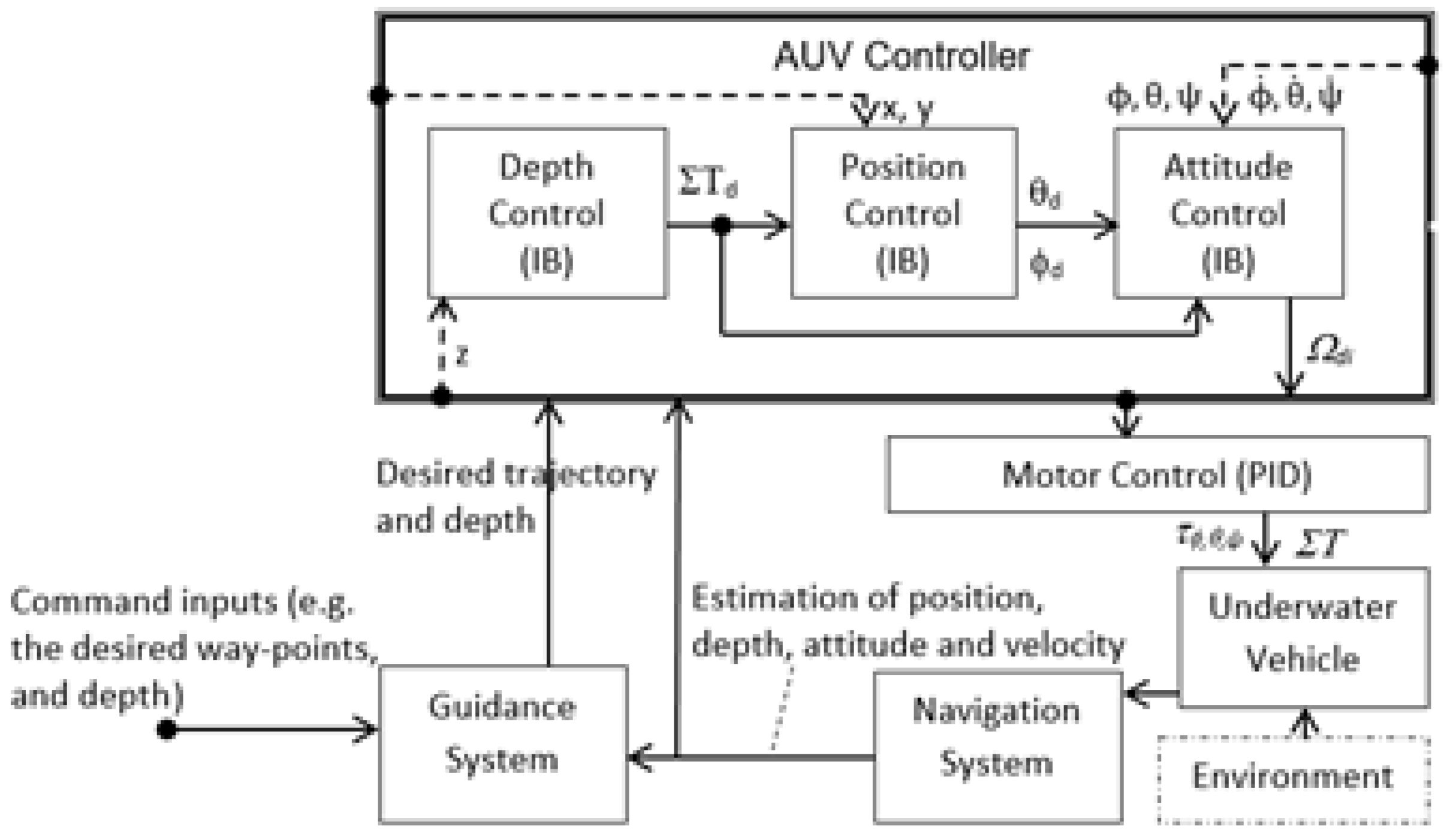
2.2. General Architecture of an AUV Controller
3. OOSEM/MDA-Based Development for an AUV Controller
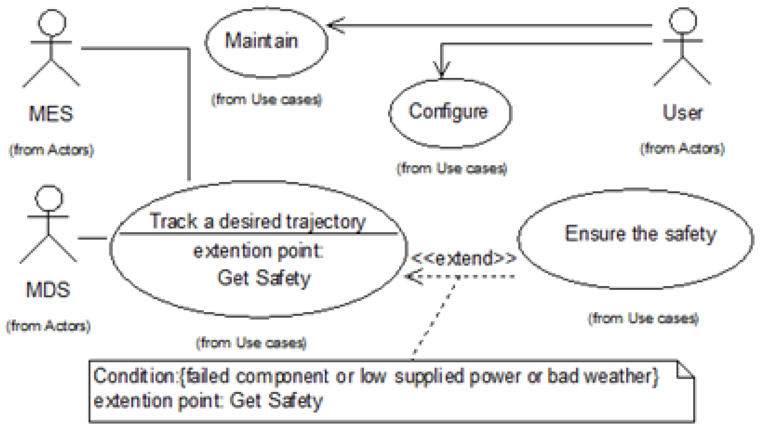
3.1. CIM Realization for AUV Controllers
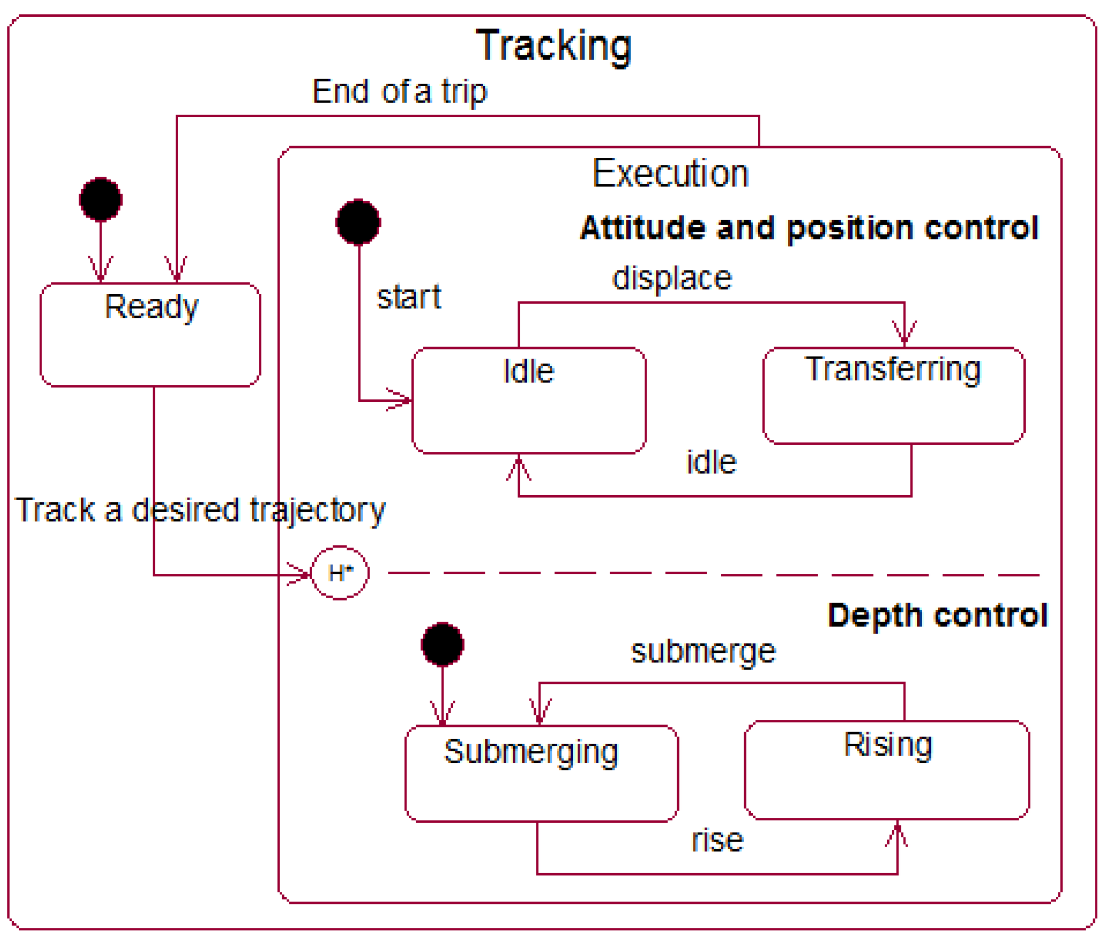
3.2. PIM Realization for AUV Controllers
| Algorithm 1. Navigation filter followed up by a UKF filter |
| Function UKF-based algorithm Step UKF prediction Data: Result: end Step UKF updating Data: Result: end |
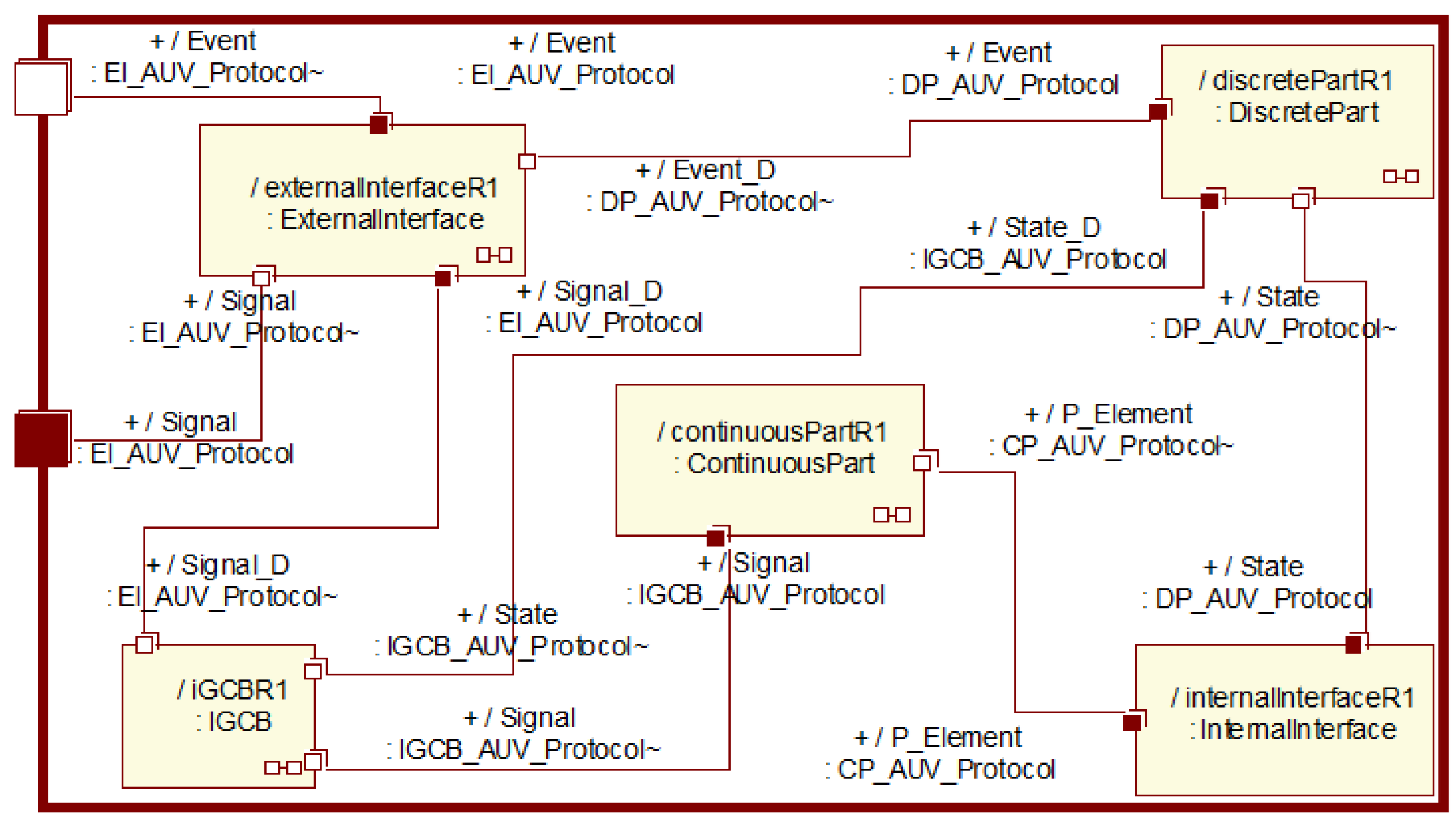
3.3. PSM Implementation for an AUV Controller
4. Application
5. Conclusions and Future Work
Author Contributions
Funding
Data Availability Statement
Conflicts of Interest
References
- Sivčev, S.; Coleman, J.; Omerdić, E.; Dooly, G.; Toal, D. Underwater manipulators: A review. Ocean Eng. 2018, 163, 431–450. [Google Scholar] [CrossRef]
- Petillot, Y.R.; Antonelli, G.; Casalino, G.; Ferreira, F. Underwater Robots: From Remotely Operated Vehicles to Intervention-Autonomous Underwater Vehicles. IEEE Robot. Autom. Mag. 2019, 26, 94–101. [Google Scholar] [CrossRef]
- Bao, J.; Li, D.; Qiao, X.; Rauschenbach, T. Integrated navigation for autonomous underwater vehicles in aquaculture: A review. Inf. Process. Agric. 2020, 7, 139–151. [Google Scholar] [CrossRef]
- AUVAC. Autonomous Undersea Vehicles Applications Center. 2022. Available online: https://auvac.org/ (accessed on 1 February 2022).
- Henzinger, T.A.; Kopke, P.W.; Puri, A.; Varaiya, P. What’s Decidable about Hybrid Automata? J. Comput. Syst. Sci. 1998, 57, 94–124. [Google Scholar] [CrossRef]
- Carloni, L.P.; Passerone, R.; Pinto, A.; Sangiovanni-Vincentelli, A.L. Languages and Tools for Hybrid Systems Design. Found. Trends Electron. Des. Autom. 2006, 1, 1–193. [Google Scholar] [CrossRef]
- Fishwick, P.A. Handbook of Dynamic System Modeling; Taylor & Francis Group: Abingdon, UK, 2007. [Google Scholar] [CrossRef]
- EL Hamidi, K.; Mjahed, M.; El Kari, A.; Ayad, H. Neural Network and Fuzzy-logic-based Self-tuning PID Control for Quadcopter Path Tracking. Stud. Inform. Control 2019, 28, 401–412. [Google Scholar] [CrossRef]
- Karimi, H.R. A sliding mode approach to H∞ synchronization of master–slave time-delay systems with Markovian jumping parameters and nonlinear uncertainties. J. Frankl. Inst. 2012, 349, 1480–1496. [Google Scholar] [CrossRef]
- Sarhadi, P.; Noei, A.R.; Khosravi, A. Model reference adaptive PID control with anti-windup compensator for an autonomous underwater vehicle. Robot. Auton. Syst. 2016, 83, 87–93. [Google Scholar] [CrossRef]
- Wan, J.; He, B.; Wang, D.; Yan, T.; Shen, Y. Fractional-Order PID Motion Control for AUV Using Cloud-Model-Based Quantum Genetic Algorithm. IEEE Access 2019, 7, 124828–124843. [Google Scholar] [CrossRef]
- Bingul, Z.; Gul, K. Intelligent-PID with PD Feedforward Trajectory Tracking Control of an Autonomous Underwater Vehicle. Machines 2023, 11, 300. [Google Scholar] [CrossRef]
- Yan, Z.; Yang, Z.; Zhang, J.; Zhou, J.; Jiang, A.; Du, X. Trajectory Tracking Control of UUV Based on Backstepping Sliding Mode with Fuzzy Switching Gain in Diving Plane. IEEE Access 2019, 7, 166788–166795. [Google Scholar] [CrossRef]
- Bao, H.; Zhu, H. Modeling and Trajectory Tracking Model Predictive Control Novel Method of AUV Based on CFD Data. Sensors 2022, 22, 4234. [Google Scholar] [CrossRef] [PubMed]
- Guerrero, J.; Torres, J.; Creuze, V.; Chemori, A.; Campos, E. Saturation based nonlinear PID control for underwater vehicles: Design, stability analysis and experiments. Mechatronics 2019, 61, 96–105. [Google Scholar] [CrossRef]
- Liu, L.; Zhang, L.; Pan, G.; Zhang, S. Robust yaw control of autonomous underwater vehicle based on fractional-order PID controller. Ocean Eng. 2022, 257, 111493. [Google Scholar] [CrossRef]
- Alaeddini, A.; Morgansen, K.A.; Mesbahi, M. Augmented state feedback for improving observability of linear systems with nonlinear measurements. Syst. Control Lett. 2019, 133, 104520. [Google Scholar] [CrossRef]
- Makdah, A.A.R.A.; Daher, N.; Asmar, D.; Shammas, E. Three-dimensional trajectory tracking of a hybrid autonomous underwater vehicle in the presence of underwater current. Ocean Eng. 2019, 185, 115–132. [Google Scholar] [CrossRef]
- Lei, M. Nonlinear diving stability and control for an AUV via singular perturbation. Ocean Eng. 2020, 197, 106824. [Google Scholar] [CrossRef]
- Khalaji, A.K.; Tourajizadeh, H. Nonlinear Lyapounov based control of an underwater vehicle in presence of uncertainties and obstacles. Ocean Eng. 2020, 198, 106998. [Google Scholar] [CrossRef]
- Liu, J.; Zhao, M.; Qiao, L. Adaptive barrier Lyapunov function-based obstacle avoidance control for an autonomous underwater vehicle with multiple static and moving obstacles. Ocean Eng. 2022, 243, 110303. [Google Scholar] [CrossRef]
- Cho, G.R.; Park, D.-G.; Kang, H.; Lee, M.-J.; Li, J.-H. Horizontal Trajectory Tracking of Underactuated AUV using Backstepping Approach. IFAC-PapersOnLine 2019, 52, 174–179. [Google Scholar] [CrossRef]
- Du, P.; Yang, W.; Wang, Y.; Hu, R.; Chen, Y.; Huang, S. A novel adaptive backstepping sliding mode control for a lightweight autonomous underwater vehicle with input saturation. Ocean Eng. 2022, 263, 112362. [Google Scholar] [CrossRef]
- Yan, Z.; Wang, M.; Xu, J. Robust adaptive sliding mode control of underactuated autonomous underwater vehicles with uncertain dynamics. Ocean Eng. 2019, 173, 802–809. [Google Scholar] [CrossRef]
- Su, B.; Wang, H.-B.; Wang, Y. Dynamic event-triggered formation control for AUVs with fixed-time integral sliding mode disturbance observer. Ocean Eng. 2021, 240, 109893. [Google Scholar] [CrossRef]
- OMG. SysML Specifications Version 1.6: OMG Formal. 2019. Available online: https://www.omg.org/spec/SysML/ (accessed on 1 August 2024).
- Lykins, H.; Friedenthal, S.; Meilich, A. 4.4.4 Adapting UML for an Object Oriented Systems Engineering Method (OOSEM). INCOSE Int. Symp. 2000, 10, 490–497. [Google Scholar] [CrossRef]
- Pearce, P.; Hause, M.C. ISO-15288, OOSEM and Model-Based Submarine Design. In Proceedings of the 6th Asia Pacific Conference on Systems Engineering, Deep Blue Tech, Brisbane, Australia, July 2012. [Google Scholar]
- INCOSE. Object-Oriented SE Method. 2020. Available online: https://www.incose.org/incose-member-resources/working-groups/transformational/object-oriented-se-method (accessed on 1 August 2024).
- INCOSE. Systems Engineering Vision 2025; INCOSE: San Diego, CA, USA, 2014; pp. 2111–2222. [Google Scholar]
- International Council on Systems Engineering (INCOSE). Available online: https://www.incose.org/ (accessed on 25 June 2012).
- OMG. Model Driven Architecture (MDA): Guide Revision 2.0 of MDA Guide Version 1.0.1 (12 June 2003). OMG Document ormsc/2014-06-01. 2014. Available online: http://www.omg.org/cgi-bin/doc?ormsc/14-06-01 (accessed on 1 June 2014).
- Agner, L.T.W.; Soares, I.W.; Stadzisz, P.C.; Simão, J.M. A Brazilian survey on UML and model-driven practices for embedded software development. J. Syst. Softw. 2013, 86, 997–1005. [Google Scholar] [CrossRef]
- Rashid, M.; Anwar, M.W.; Khan, A.M. Toward the tools selection in model based system engineering for embedded systems—A systematic literature review. J. Syst. Softw. 2015, 106, 150–163. [Google Scholar] [CrossRef]
- Freire, L.O.; Oliveira, L.M.; Vale, R.T.; Medeiros, M.; Diana, R.E.; Lopes, R.M.; Pellini, E.L.; de Barros, E.A. Development of an AUV control architecture based on systems engineering concepts. Ocean Eng. 2018, 151, 157–169. [Google Scholar] [CrossRef]
- Van Hien, N.; Van He, N.; Diem, P.G. A model-driven implementation to realize controllers for Autonomous Underwater Vehicles. Appl. Ocean Res. 2018, 78, 307–319. [Google Scholar] [CrossRef]
- Soriano, T.; Hien, N.; Tuan, K.; Anh, T. An object-unified approach to develop controllers for autonomous underwater vehicles. Mechatronics 2016, 35, 54–70. [Google Scholar] [CrossRef]
- Anwar, M.W.; Rashid, M.; Azam, F.; Kashif, M. Model-based design verification for embedded systems through SVOCL: An OCL extension for SystemVerilog. Des. Autom. Embed. Syst. 2017, 21, 1–36. [Google Scholar] [CrossRef]
- Soriano, T.; Pham, H.A.; Ngo, V.H. Analysis of coordination modes for multi-UUV based on Model Driven Architecture. In Proceedings of the 12th France-Japan and 10th Europe-Asia Congress on Mechatronics, Tsu, Japan, 10–12 September 2018; IEEE: Piscataway, NJ, USA. [Google Scholar] [CrossRef]
- OMG. UML Profile for MARTE: UML for Model-Driven Development of Real Time and Embedded Systems (RTES). OMG formal/19-04-02. 2019. Available online: https://www.omg.org/spec/MARTE/ (accessed on 2 April 2019).
- Selić, B.; Gérard, S. Modeling and Analysis of Real-Time and Embedded Systems with UML and MARTE; Elsevier: Amsterdam, The Netherlands, 2014. [Google Scholar]
- Selic, B. Using UML for Modeling Complex Real-Time Systems; Lecture Notes in Computer Science; Springer: Berlin/Heidelberg, Germany, 1998; pp. 250–260. [Google Scholar] [CrossRef]
- SNAME. Nomenclature for Treating the Motion of a Submerged Body through a Fluid; SNAME: New York, NY, USA, 1950. [Google Scholar]
- Fossen, T.I. Handbook of Marine Craft Hydrodynamics and Motion Control, 2nd ed.; John Wiley & Sons: Chichester, UK, 2021. [Google Scholar]
- Allotta, B.; Caiti, A.; Costanzi, R.; Fanelli, F.; Fenucci, D.; Meli, E.; Ridolfi, A. A new AUV navigation system exploiting unscented Kalman filter. Ocean Eng. 2016, 113, 121–132. [Google Scholar] [CrossRef]
- Hien, N.V.; He, N.V.; Truong, V.T.; Diem, P.G. Using the Real-Time Unified Modeling Language to Implement an AUV Controller; Research Project Report, Funded by State of Vietnam, KC03.TN05/11-15; Hanoi University of Science and Technology: Hanoi, Vietnam, 2013. [Google Scholar]
- IBM. IBM Rational’s Methodology, Software, Online Documentation and Training Kits. 2022. Available online: https://www.ibm.com/academic/home (accessed on 1 April 2022).
- OpenModelica. OpenModelica Software, Version 1.18. 2022. Available online: https://www.openmodelica.org/ (accessed on 1 February 2022).
- u-blox. Product Selector. 2022. Available online: https://www.u-blox.com/en/product-search (accessed on 1 January 2022).
- InvenSense. Sensor System on Chip. 2022. Available online: http://www.invensense.com/ (accessed on 1 January 2022).
- Arduino Reference. Available online: https://www.arduino.cc/ (accessed on 1 March 2022).


| Used Control Techniques | Assessment of the Performance of AUVs for Control Applications | ||
|---|---|---|---|
| Control Task | Stability | Comments | |
| Proportional integral derivative (PID) controller [15,16] | For AUV trajectory tracking | Not very stable against disturbances or nonlinear systems | Easy to design; response time tapers off with stability; sensitive to noises |
| Linear quadratic regulator (LQR) [17,18] | For AUV heading control and trajectory tracking | Average stability against disturbances | State and noise need to be estimated; better for linear models |
| Lyapunov stability [19,20,21] | For AUV heading control | Not very stable in the surrounding area of the desired waypoints | For linear and nonlinear systems; expert knowledge is required to find Lyapunov functions |
| Backstepping technique [22,23] | For AUV heading control and trajectory tracking | Stable against high disturbances | For linear and nonlinear systems; can deal with uncertainty models |
| Sliding mode control [24,25] | For AUV heading control and trajectory tracking | Average stability against disturbances | For linear and nonlinear systems; chattering effect; no finite time convergence |
| DOF | Motions | Forces/Moments | Linear/Angular Velocities | Position/Euler Angles |
|---|---|---|---|---|
| 1 | Surge | X | u | x |
| 2 | Sway | Y | v | y |
| 3 | Heave | Z | w | z |
| 4 | Roll | K | p | ϕ |
| 5 | Pitch | M | q | θ |
| 6 | Yaw | N | r | ψ |
| Specifications | Value |
|---|---|
| L × W × H | (1.26 × 0.61 × 0.40) m |
| Operating time | 20 min |
| Dry weight | 21.20 kg |
| 2 × Li-Po battery | 22.2 V, 20,000 mAh |
| Max. capacity | 324 W |
| Max. submerged depth | 1.20 m |
| Max. radius of operation | 450 m |
| Max. submerging or rising speed | 0.30 m/s |
| Max. horizontal speed | 1.80 m/s |
| No. | Predetermined Course Angle (deg) | Average Velocity (m/s) | Time of Stabilized Course (s) |
|---|---|---|---|
| 1 | 10 | 1.0 | 6.90 |
| 2 | 10 | 1.5 | 6.10 |
| 3 | 20 | 1.0 | 7.20 |
| 4 | 20 | 1.5 | 6.40 |
| 5 | 30 | 1.0 | 7.30 |
| 6 | 30 | 1.5 | 7.10 |
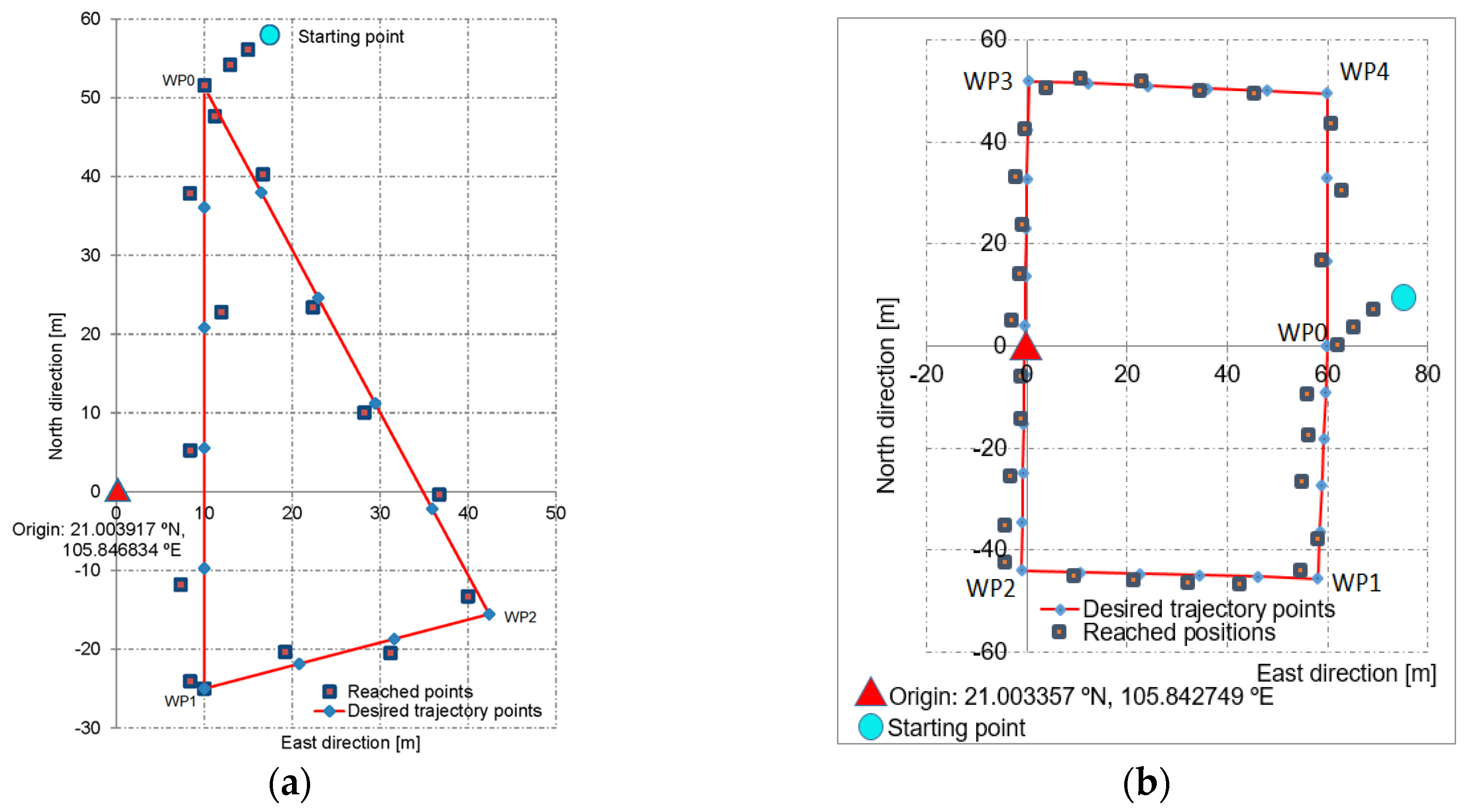
| WP-Based Path Generation | RMS Deviation (m) | Max. Deviation (m) | ||
|---|---|---|---|---|
| Along East Axis | Along North Axis | Along East Axis | Along North Axis | |
| WP0–WP1 | 3.51552 | 3.82270 | 4.07784 | 4.24404 |
| WP1–WP2 | 2.60232 | 3.34176 | 4.06368 | 4.30740 |
| WP2–WP0 | 2.35188 | 5.01288 | 2.79348 | 7.67352 |
| WP-Based Path Generation | RMS Deviation (m) | Max. Deviation (m) | ||
|---|---|---|---|---|
| Along East Axis | Along North Axis | Along East Axis | Along North Axis | |
| WP0–WP1 | 2.7036 | 3.0876 | 2.9207 | 3.4398 |
| WP1–WP2 | 1.7465 | 2.1935 | 2.3279 | 2.8723 |
| WP2–WP3 | 2.0754 | 2.6527 | 2.2675 | 2.0894 |
| WP3–WP4 | 2.0532 | 2.0921 | 2.2793 | 2.7260 |
| WP4–WP0 | 1.7270 | 1.5573 | 1.9874 | 1.7674 |
Disclaimer/Publisher’s Note: The statements, opinions and data contained in all publications are solely those of the individual author(s) and contributor(s) and not of MDPI and/or the editor(s). MDPI and/or the editor(s) disclaim responsibility for any injury to people or property resulting from any ideas, methods, instructions or products referred to in the content. |
© 2024 by the authors. Licensee MDPI, Basel, Switzerland. This article is an open access article distributed under the terms and conditions of the Creative Commons Attribution (CC BY) license (https://creativecommons.org/licenses/by/4.0/).
Share and Cite
Sang, C.D.; He, N.V.; Hien, N.V.; Khuyen, N.T. An OOSEM-Based Design Pattern for the Development of AUV Controllers. J. Mar. Sci. Eng. 2024, 12, 1342. https://doi.org/10.3390/jmse12081342
Sang CD, He NV, Hien NV, Khuyen NT. An OOSEM-Based Design Pattern for the Development of AUV Controllers. Journal of Marine Science and Engineering. 2024; 12(8):1342. https://doi.org/10.3390/jmse12081342
Chicago/Turabian StyleSang, Cao Duc, Ngo Van He, Ngo Van Hien, and Nguyen Trong Khuyen. 2024. "An OOSEM-Based Design Pattern for the Development of AUV Controllers" Journal of Marine Science and Engineering 12, no. 8: 1342. https://doi.org/10.3390/jmse12081342