Article

Experimental Research on the Low-Cycle Fatigue Crack Growth Rate for a Stiffened Plate of EH36 Steel for Use in Ship Structures

1
Key Laboratory of High Performance Ship Technology, Wuhan University of Technology, Ministry of Education, Wuhan 430063, China
2
School of Naval Architecture, Ocean and Energy Power Engineering, Wuhan University of Technology, Wuhan 430063, China
3
School of Civil Engineering and Architecture, Wuhan Polytechnic University, Wuhan 430048, China
*
Author to whom correspondence should be addressed.
J. Mar. Sci. Eng. 2024, 12(8), 1365; https://doi.org/10.3390/jmse12081365
Submission received: 17 June 2024 / Revised: 29 July 2024 / Accepted: 8 August 2024 / Published: 11 August 2024
(This article belongs to the Special Issue Safety and Reliability of Ship and Ocean Engineering Structures)

Abstract

:
This paper presents a straightforward approach for determining the low-cycle fatigue (LCF) crack propagation rate in stiffened plate structures containing cracks. The method relies on both the crack tip opening displacement (CTOD) and the accumulative plastic strain, offering valuable insights for ship structure design and assessing LCF strength. Meanwhile, the LCF crack growth tests for the EH36 steel were conducted on stiffened plates with single-side cracks and central cracks under different loading conditions. The effects of stress amplitude, stress ratio, and stiffener position on the crack growth behavior were examined. Fitting and verifying analyses of the test data were employed to investigate the relationship between CTOD and the crack growth rate of EH36 steel under LCF conditions. The results showed that the proposed CTOD-based prediction method can accurately characterize the LCF crack growth behavior for stiffened plate of EH36 steel for use in ship structures.

1. Introduction

Since the beginning of the 21st century, driven by the increasing demand for deep-sea defense and the significant growth in international trade, ships have been gradually evolving to be larger sizes. In order to meet the demand for lightweight vessel construction, the use of high-strength steel has significantly increased, leading to greater overall deformation and stress levels in ship structures. Particularly during navigation in harsh sea conditions, ships experience periodic extreme cyclic loading, causing the stress levels in localized areas (such as deck side plates and hatch corner junctions) to reach or even exceed the material’s yield strength, resulting in low-cycle fatigue damage, the formation of cracks, and leading to incidents of ship hull fracture and sinking. This phenomenon has become one of the most critical issues requiring focused attention in the design and construction of large-scale vessels.
Considering the increasing occurrence of low-cycle fatigue phenomena resulting from the use of high-strength steel in ship structures, scholars have carried out extensive research on the crack propagation behavior of low-cycle fatigue under different structural configurations, materials, and loading conditions, employing various research methodologies [1,2,3]. This research primarily encompasses theoretical, numerical, and experimental methods. The theoretical investigations focus on establishing relationships between crack propagation rates and fracture parameters (K, J, CTOD, G) [4,5,6,7,8,9,10,11,12,13] to describe crack growth behaviors. Numerical simulations, valued for their wide applicability, robust solutions, and cost-effectiveness, are widely employed in studying crack propagation. Low-cycle fatigue crack propagation experiments are crucial for investigating how applied loading affects crack growth behaviors across different materials and structural forms. Researchers globally have conducted such experiments to gain insights into these phenomena.
Since the early 1950s, scholars both domestically and abroad have been engaged in research on the low-cycle fatigue crack growth behavior. Initially, researchers focused on the investigation of fatigue crack growth behavior under constant amplitude loading to elucidate the mechanisms and patterns of crack propagation. In the 1970s, the United States military [14] conducted full-scale low-cycle fatigue crack propagation tests on actual large-scale submarine structures to study their crack propagation behavior. In the 1990s, Chen [15] conducted low-cycle fatigue tests on scaled-down models of large submarines, obtaining fracture toughness and intrinsic crack propagation rate curves for 921A steel. Li [16] studied the low-cycle fatigue crack propagation behavior of different steels used in ships and submarines (5NiCrMoV-I, 5NiCrMoV-II, EH36, etc.) through experimental methods, establishing the relationship between the crack propagation rate and the total strain range and plastic strain range. Liu [17] conducted low-cycle fatigue crack growth experiments on flat and stiffened plates under cyclic tensile loading, studying the crack propagation patterns of damaged ship structures and proposing criteria for the formation and propagation of cracks in damaged ship structures under fatigue loading. In recent years, Digital Image Correlation (DIC) technology has been applied to a range of crack-related issues. Jandejsek [18] utilized two-dimensional DIC technology to analyze the full-field stress and strain in the crack region of compact tension specimens, from which they extracted fracture parameters including the J-integral and CTOD. Zhang [19] combined DIC technology with material constitutive relationships to obtain the size of the forward and reverse plastic zones of Al-7075-T6 steel under cyclic loading. Vasco-Olmo [20] utilized DIC technology to measure the CTOD of compact tension specimens and applied the compliance deviation method to separate it into elastic and plastic components.
XFEM was established by Belytschko [21] based on the Partition of Unity Finite Element Method proposed by Melenk and Babuška [22]. This method introduces the enrichment functions of crack tips into the finite element approximation field, effectively addressing the discontinuity issue in crack propagation simulations by extending the degrees of freedom of nodes in penetrating crack elements. XFEM does not require predefined cracks and enables cracks to propagate in arbitrary directions; thus, it is suitable for situations where the crack propagation directions are unknown but exhibits some irregularity in describing stress fields at the tips of cracks. Consequently, XFEM is often employed for predicting crack propagation paths during dynamic crack growth or calculating fracture parameters during (quasi-) static crack growth. He [23] predicted the paths and lifespans of low-cycle fatigue crack propagation in beam structures containing cracks using the direct cyclic step algorithm in ABAQUS 14.5, and conducted comparative verification through corresponding experiments. Tu [24] studied the influence of factors such as different overload ratios, overload intervals, and loading sequences on the crack growth behavior of compact tension specimens using XFEM, showing strong correlation with experimental findings. Huang [25] utilized the Debond method and the ABAQUS software to predict the residual strength and load-crack propagation increment curve for centrally cracked tensile specimens with different initial crack lengths. They compared the results with experimental data and found the error to be less than 6%. Hwang [26] conducted simulation analyses of crack tip deformation and stress fields under monotonic loading and large cyclic loading conditions using the Debond method. Their comparison with experimental results exhibited excellent consistency. Xiong [27], based on the Debond method, employed finite element analysis to investigate the crack propagation behavior of ship panel structures with cracks under biaxial low-cycle fatigue loading. They explored the influence of various loading factors (load ratio, load amplitude, biaxial load ratio, etc.) on fracture parameters, offering guidance for predicting crack propagation behavior in ship panel structures under biaxial loading conditions.
The stiffened plate structure possesses a strong stability and is widely used in ships and marine structures, constituting complex hull panel frameworks. Consequently, the fatigue crack life issues of the stiffened plate structure significantly impact the overall fatigue life of ships and marine structures [28]. Longitudinal stiffened plates in the ship hull experience longitudinal tensile stresses induced by the overall longitudinal bending of the hull, and cracks are likely to initiate at the connections between the stiffeners and plates, further propagating in the transverse direction [29]. The initiation and growth behavior of cracks in the stiffened plate structure are more intricate compared to flat plate structures, prompting numerous scholars to conduct extensive research in the field. Duncheva [30] conducted empirical investigations to assess the impact of varied opening processing techniques and welding methodologies on the crack initiation life of S355 steel T-section stiffened plate structures featuring non-circular openings. In a separate study, Lei [31] performed a comprehensive series of fatigue tests on 921A steel welded stiffened plates incorporating water jet holes. Their research focused on elucidating the effects of low-cycle fatigue loading characteristics, specifically load amplitude and load ratio, on the initiation life of cracks. Dexter [32] delved into the influence of factors such as welding residual stress and water jet holes on crack growth rates. This was achieved through an extensive series of long crack propagation tests conducted on welded stiffened plates. Jiang [33] systematically compared the crack growth characteristics under low-cycle fatigue loading conditions for specimens with identical principal dimensions, distinguishing between flat plates and stiffened plates through rigorous experimental methodologies. Their findings revealed that the ultimate crack propagation length in all of the stiffened plate specimens surpassed that of the flat plate specimens, underscoring the restraining effect of the stiffener on crack propagation. Song [34] explored the impact of load amplitude and stiffener size and position on the fatigue life of centrally cracked stiffened plates through a set of detailed crack propagation experiments. The results suggested that augmenting the height of stiffener or diminishing the spacing between stiffener proved advantageous in extending the crack growth life of stiffened plate structures.
In summary, during the entire low-cycle fatigue crack process of a structure, crack propagation behavior is crucial and cannot be overlooked. Despite extensive research by numerous scholars from theoretical, simulation, and experimental perspectives on the crack propagation behavior in low-cycle fatigue, there are still several unresolved issues that need to be addressed. Most studies focus on the relationship between the crack propagation rate and elasto-plastic fracture parameters in small-scale yielding, yet few can provide precise solutions for elasto-plastic fracture parameters under large-scale yielding, especially for complex structures like stiffened panels. Consequently, utilizing CTOD to represent the crack growth rate proves to be more effective in capturing variations in plasticity at the crack tip. In previous research, the author [35,36,37] delved into the analysis of CTOD variations in cracked plates subjected to cyclic loading, taking into account accumulative plastic strain. The current study builds upon the author’s previous investigations, with a specific emphasis on the development of a novel method for predicting fatigue crack growth rates for stiffened plates at large-scale yielding. To address this, a simple formula has been proposed for calculating crack growth rates by adopting CTOD under high-stress levels. Meanwhile, LCF crack growth tests for EH36 steel were conducted on stiffened plates with single-side cracks and central cracks under different loading conditions. The effects of stress amplitude, stress ratio, and stiffener position on the crack growth behavior were examined. Fitting and verifying analyses of the test data were employed to investigate the relationship between CTOD and crack growth rate of EH36 steel under LCF conditions.

2. Low Cycle Fatigue Crack Growth Experiment for Stiffened Plate

The presence of a stiffener enhances both the inherent stiffness and strength of the structure while exerting a pronounced restraining effect on crack propagation within the structure. This characteristic often enables stiffened plate structures to maintain stable growth for a considerable period after the initiation of cracks, as opposed to flat plate structures, which swiftly enter an unstable propagation phase. Therefore, investigating the crack growth characteristics of stiffened plate structures subjected to low-cycle fatigue loading is of significant importance for the precise prediction of the low-cycle fatigue life of ship structures. Experimental investigations were conducted on low-cycle fatigue crack propagation in stiffened plates with single-edge cracks and central cracks under various loading conditions. The study systematically examined the influence of factors such as load amplitude, load ratio, and the position of stiffener on the fatigue crack growth life and characteristics of the stiffened plate structure.
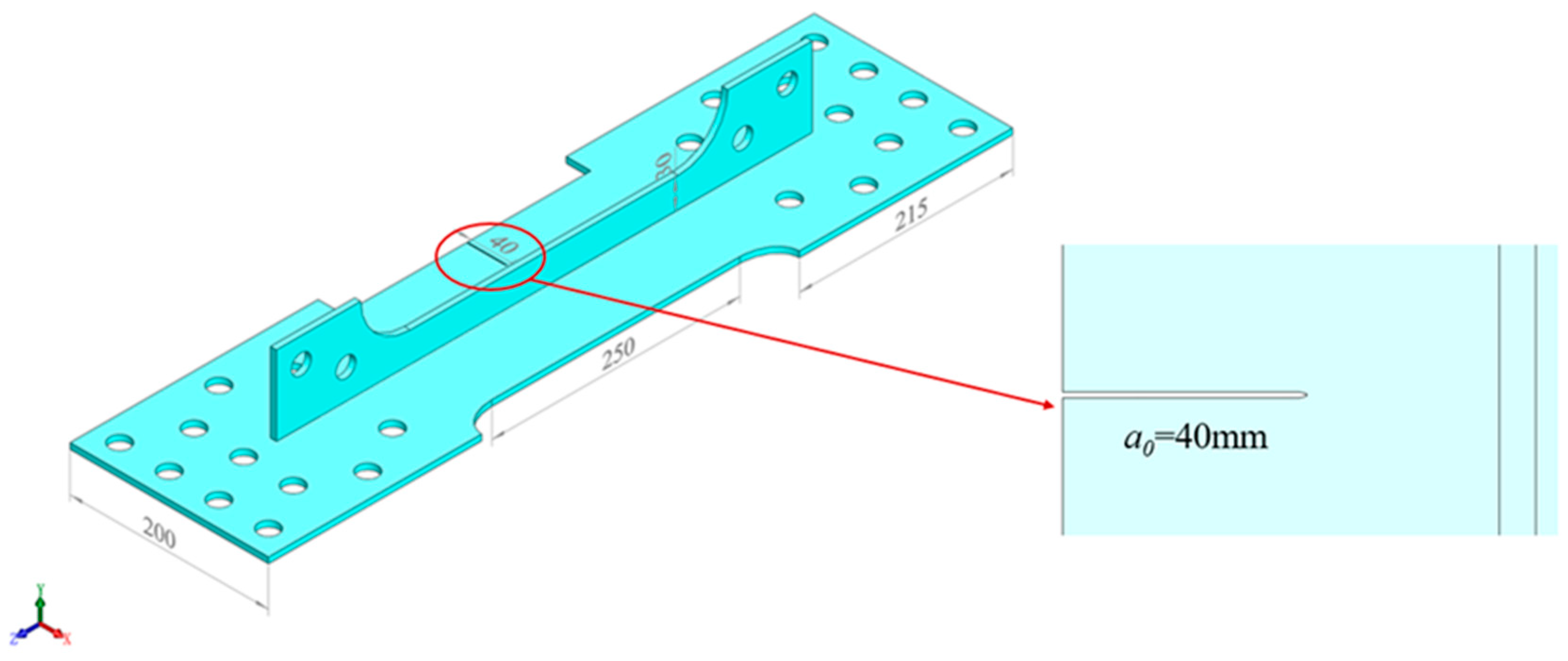
In a complete welded stiffened plate structure, cracks typically initiate and further propagate at the junction of the stiffener and the plate. Therefore, in this experiment, a specimen with a central crack in a stiffened plate, as shown in Figure 1, was designed to investigate the crack growth characteristics of stiffened plate structures. Simultaneously, stiffened plate structures in a ship’s hull are often present in the form of a stiffened panel structure. Consequently, during the crack propagation process, the crack is not only influenced by the stiffener directly above it but also constrained by distant stiffeners. To study the effect of distant stiffeners on crack growth behavior, specimens with single-edge cracks in stiffened plates, as depicted in Figure 2, were designed and fabricated. All specimens were prepared and notched using electrical discharge machining (EDM) technology, with prefabricated cracks created using a 0.12 mm diameter molybdenum wire. Additionally, to facilitate clear observations in the crack propagation images, the specimen’s surfaces were polished using an electric grinder to achieve a roughness below 0.8 μm. The total length and width of the specimen were 750 mm and 200 mm, respectively, and the thickness of the stiffened plate was 6 mm. The effective region of the specimen is outlined by the red box in the diagram, with a length of 250 mm and a width of 200 mm. Openings are incorporated into both the stiffener and the plate for specimen clamping purposes. one-quarter elliptical transition region was introduced between the clamping ends and the effective region of the specimen to ensure that crack propagation occurs within the specified effective area. To ensure uniform loading of the stiffened plate and eliminate eccentricity, the specimen was equipped with extended sections at both ends, which were connected to the fixture via bolts. The specimen was rigidly constrained at the ends of the stiffened plate by multiple sets of bolts connecting it to the workbench and the actuator head, ensuring uniform axial loading.
This study addresses the limited exploration of LCF crack growth characteristics in EH36 steel, a material extensively employed in ship and offshore structures. The research involves conducting fatigue crack propagation tests on EH36 steel subjected to low-cycle fatigue conditions. The basic mechanical properties were obtained by monotonic tensile test, the standard tensile test is conducted at a loading rate of 10 mm/min until specimen failure. To ensure the validity of the experimental data, three replicate tests were performed, and the results were averaged, as shown in Table 1.
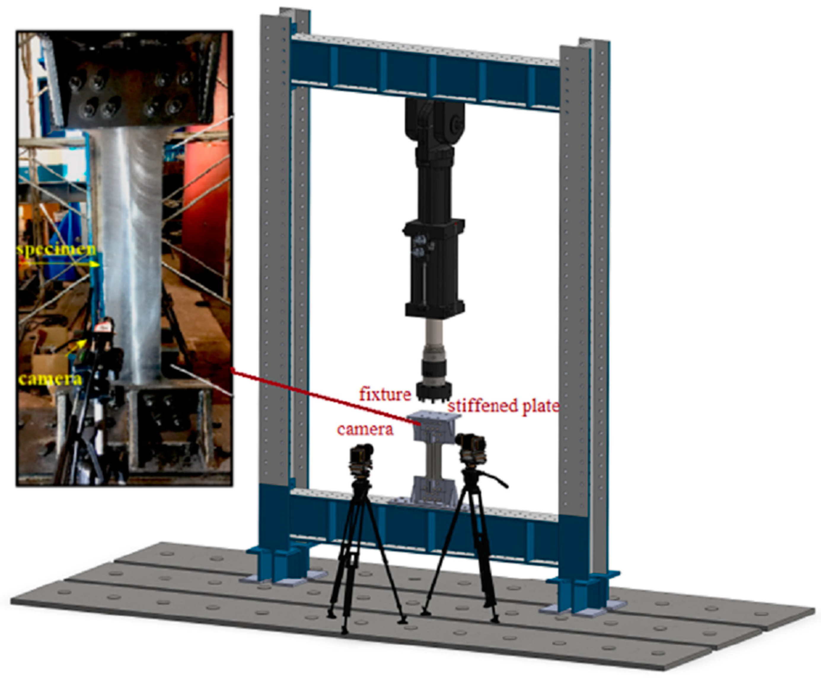
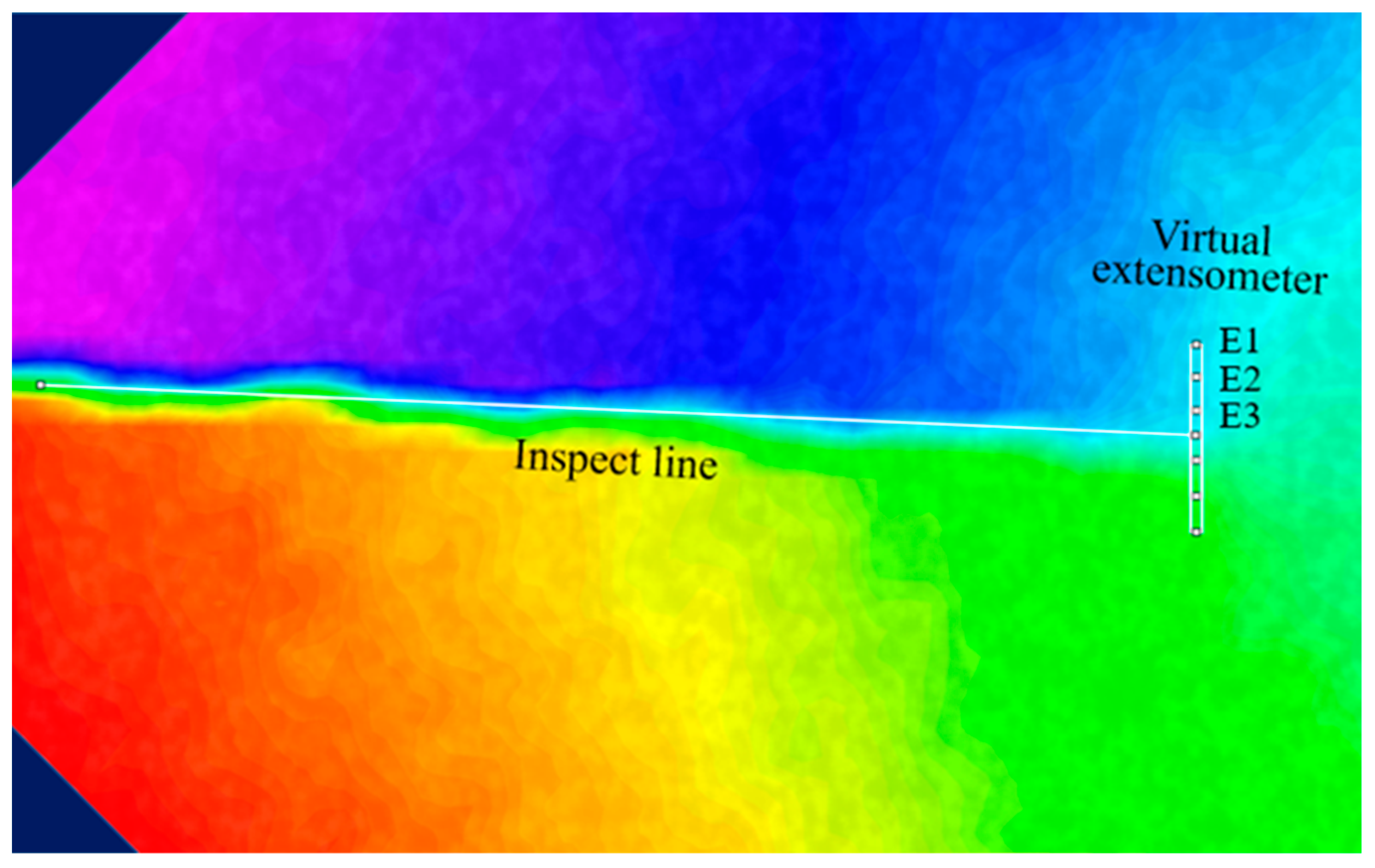
The experiment was conducted using an MTS 244.51 electro-hydraulic servo actuator. As depicted in Figure 3, the extension segments of the stiffened plate were attached to top and bottom fixtures using high-grade bolts. The top and bottom fixtures were securely fastened to the MTS loading rod and examination platform, correspondingly. An industrial camera paired with VIC-2D software was used throughout the experiment to measure crack length, CTOD, and deformation near the crack tip, as presented in Figure 4. The distance between the intersection of the elastic and plastic zones at the crack tip and the crack plane is defined as CTOD, i.e., the displacement deformation of the “Virtual extensometer” in DIC measurement corresponds to the CTOD of the specimen. DIC calculates deformation and strain via speckle images. Random speckle patterns were applied to the specimen’s surface to aid in marking deformation data. An industrial camera was positioned vertically to the stiffened plate to observe the crack propagation and measure the stress distribution on the plate. For stiffened plates with a central crack, an industrial camera was placed on each side, and for stiffened plates with a single-edge crack, an industrial camera was placed on the left side to monitor real-time crack propagation during the test.
In order to investigate the influence of factors such as stiffener presence, crack location, maximum load, and load amplitude on the low-cycle fatigue crack propagation behavior of stiffened plate structures, the study used six sets of test conditions, as presented in Table 2. Among these, a condition with a 0 mm stiffened plate was used as a reference for comparing and discussing the impact of stiffener on crack propagation behavior. The design of these conditions was guided by the results of finite element analysis. From Figure 5, it is evident that, under this particular condition, the size of the plastic zone at the crack tip of the specimen (highlighted in white in the figure) is within the same order of magnitude as the crack size, indicating extensive plastic yielding in the specimen and characterizing a low-cycle fatigue issue.
This analysis aims to examine the effects of various parameters on the fatigue crack propagation behavior in stiffened plate structures, providing insights into the relationship between stiffener, crack growth, and structural response, with a specific focus on the plasticity at the crack tip region under low-cycle fatigue conditions.

3. Result and Discussion

3.1. Experimental Results of Stiffened Plates with Single-Edge Crack

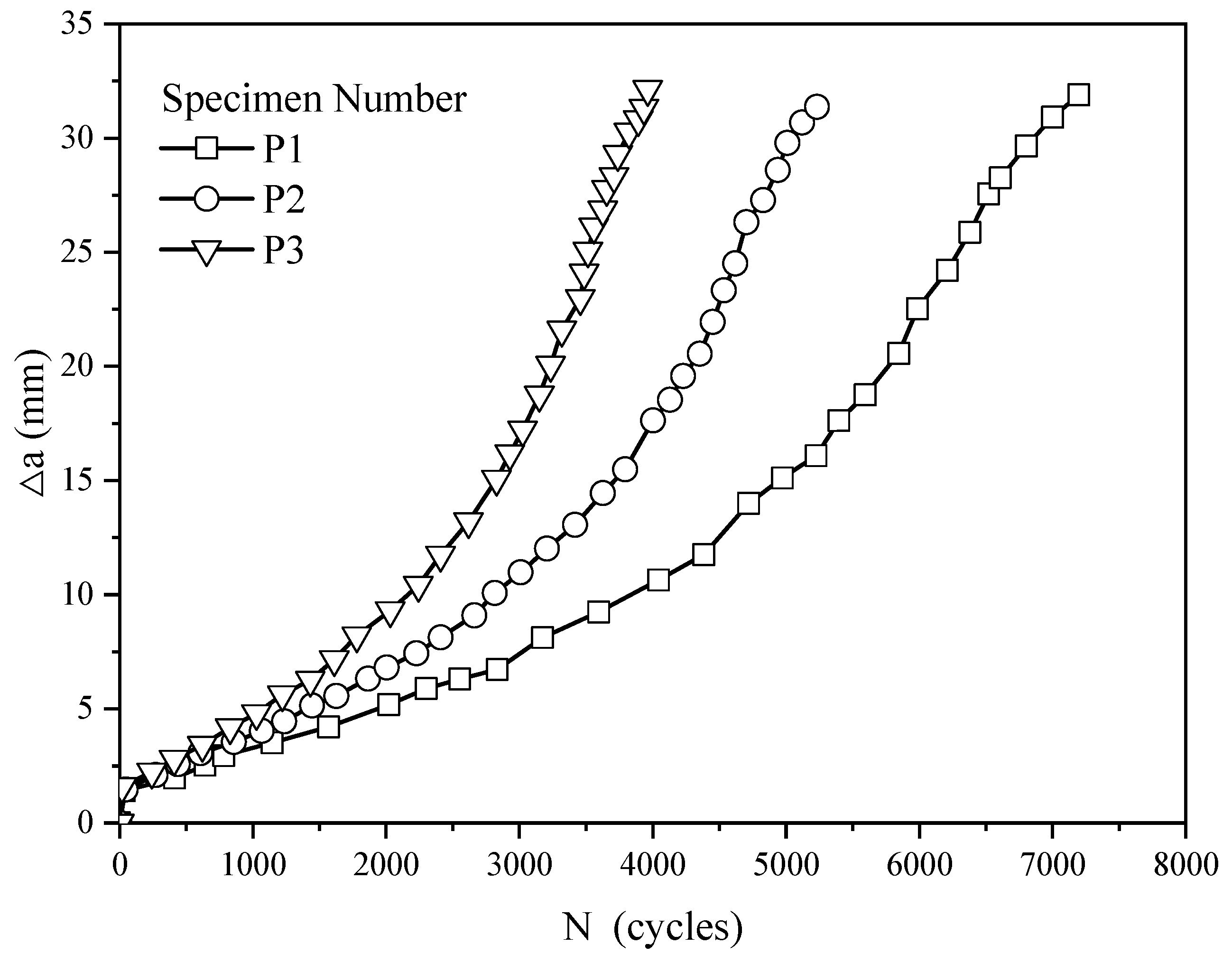
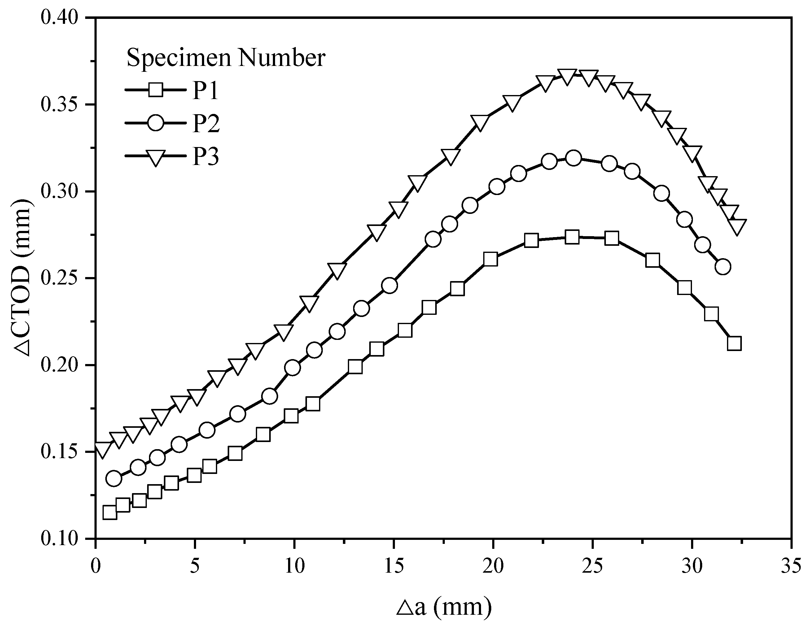
After the completion of the experiment, the measured results were plotted in Figure 6, Figure 7 and Figure 8. The variation in the crack growth increment Δa vs. cycles N is shown in Figure 6. Overall, when the load ratio is the same (R = −1), the fatigue crack growth life of stiffened plates shortens with increasing load amplitude. Observations from the crack growth rate curve in Figure 7 and the crack tip opening displacement range curve in Figure 8 reveal that when the crack tip is distant from the stiffener location (Δa ≤ 23 mm), both the ΔCTOD and crack propagation rate escalate rapidly with increasing crack length. The growth of crack length with the number of cycles seems to follow an exponential pattern. As the crack tip gradually approaches the stiffener position (Δa > 23 mm), the constraint effect of the stiffener begins to play a significant role. At this point, the ΔCTOD and crack propagation rate of the specimen decrease sharply as the crack length increases, and the increasing pattern of crack length also slows down. This phenomenon, compared to the overall increase in the crack propagation rate of the flat plate structure, exhibits a significant difference in crack propagation behavior, deserving of further research and discussion.
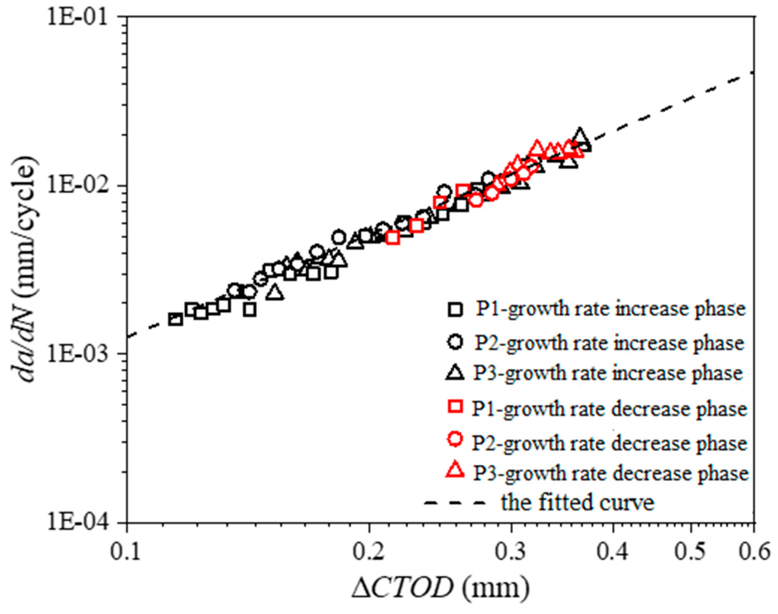
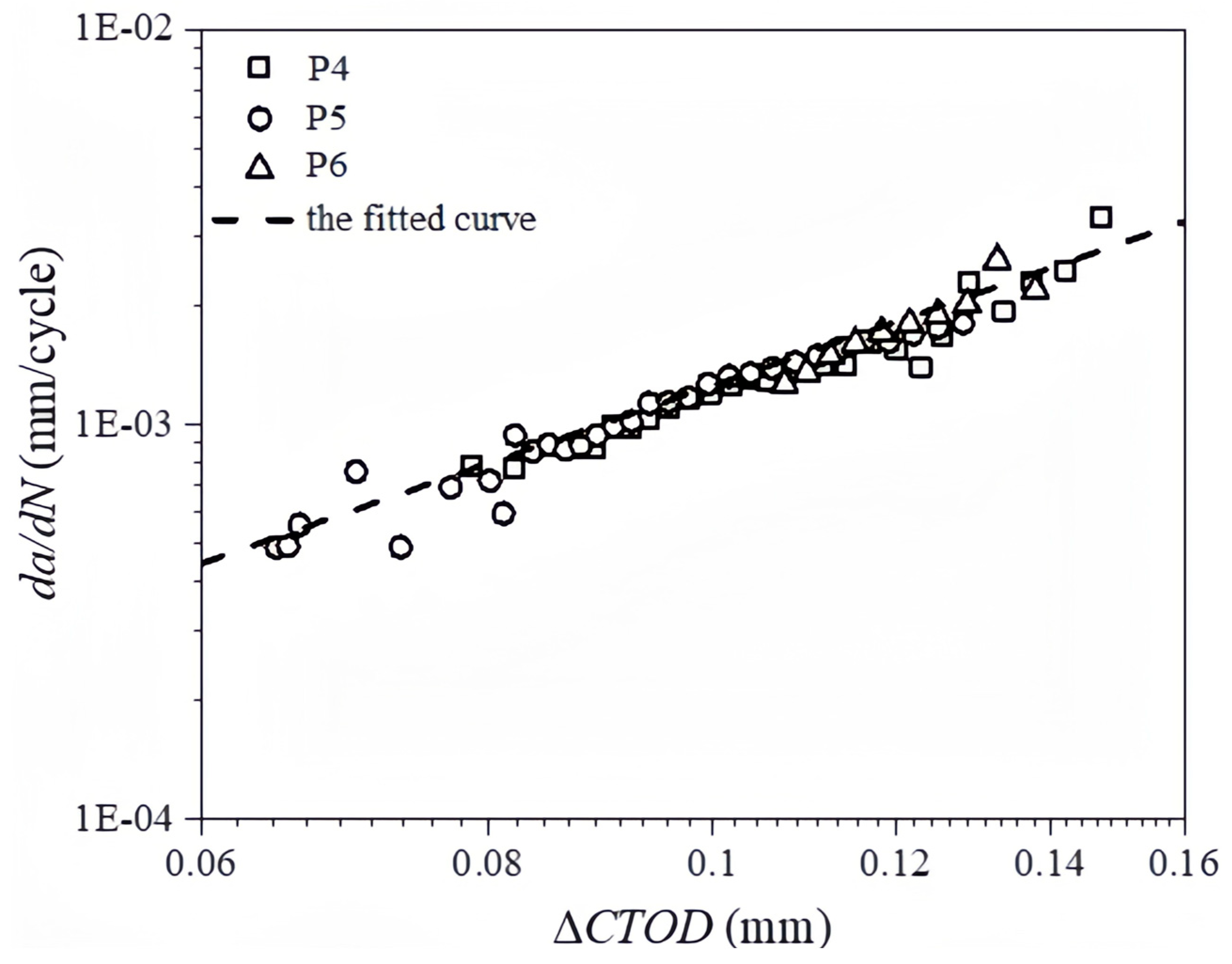
The data for the ΔCTOD and crack propagation rate are presented in Figure 9. It can be observed that, whether in the rising or falling phase of the crack propagation rate, the correlation between da/dN and ΔCTOD conforms to the intrinsic crack propagation rate model of the material. It is evident in the logarithmic coordinate system that there exists a clear linear relationship between da/dN and ΔCTOD, implying that ΔCTOD can effectively describe crack propagation rate. Utilizing the form of the Paris’s equation, the intrinsic crack propagation rate model for stiffened plate made of EH36 steel is fitted and expressed as follows:
d a d N = 0.135 ( Δ C T O D ) 2.0312

3.2. Experimental Results of Stiffened Plates with Central Crack

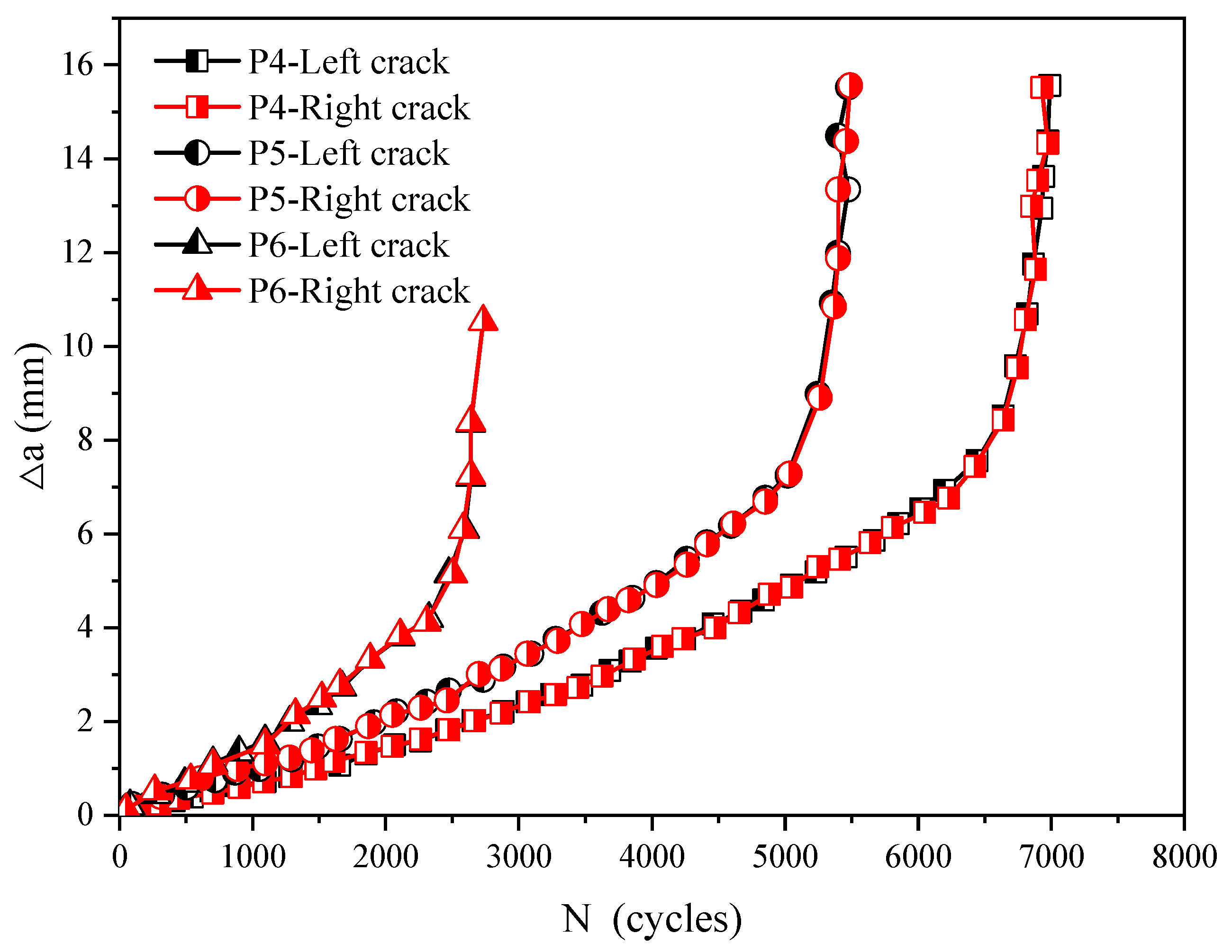
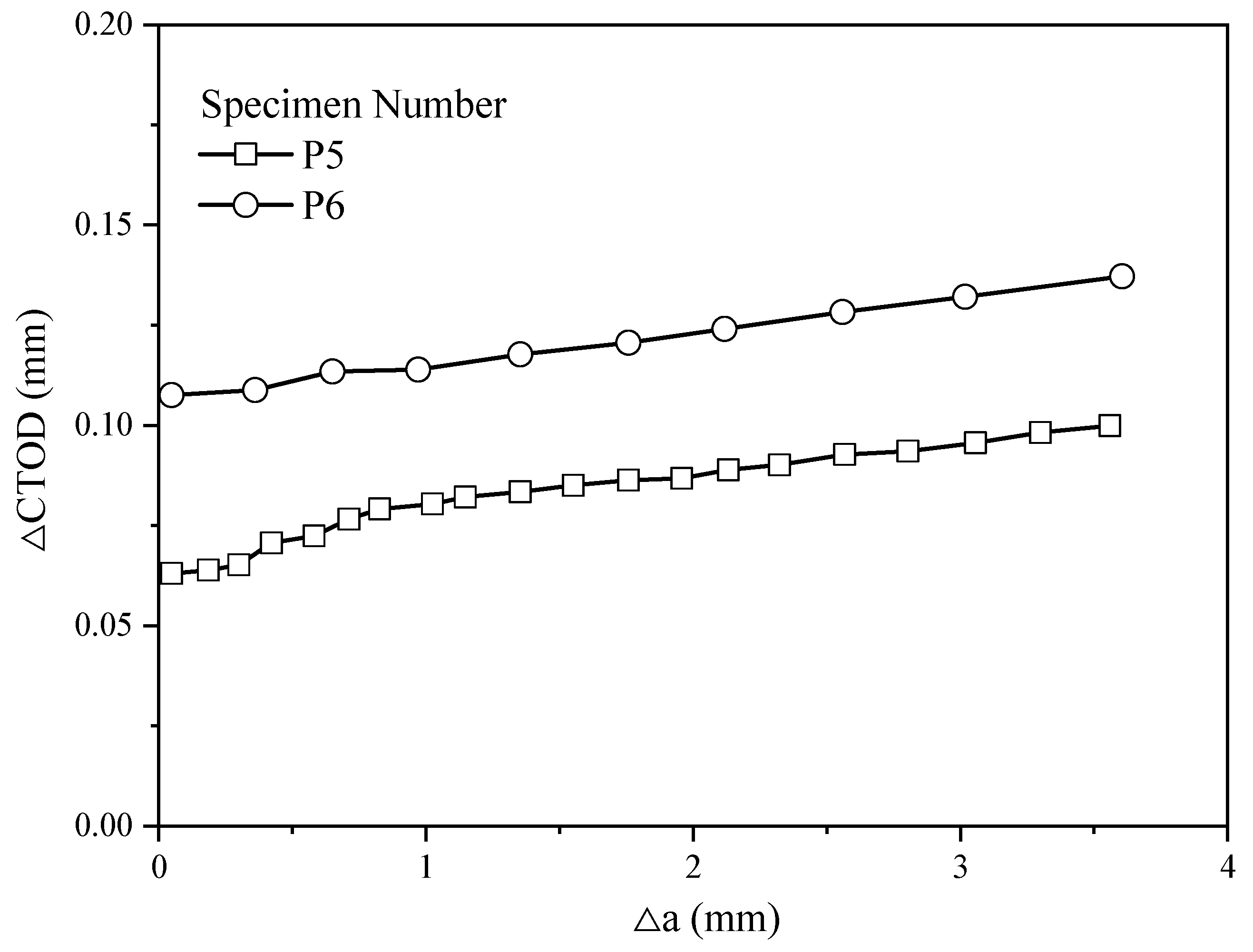
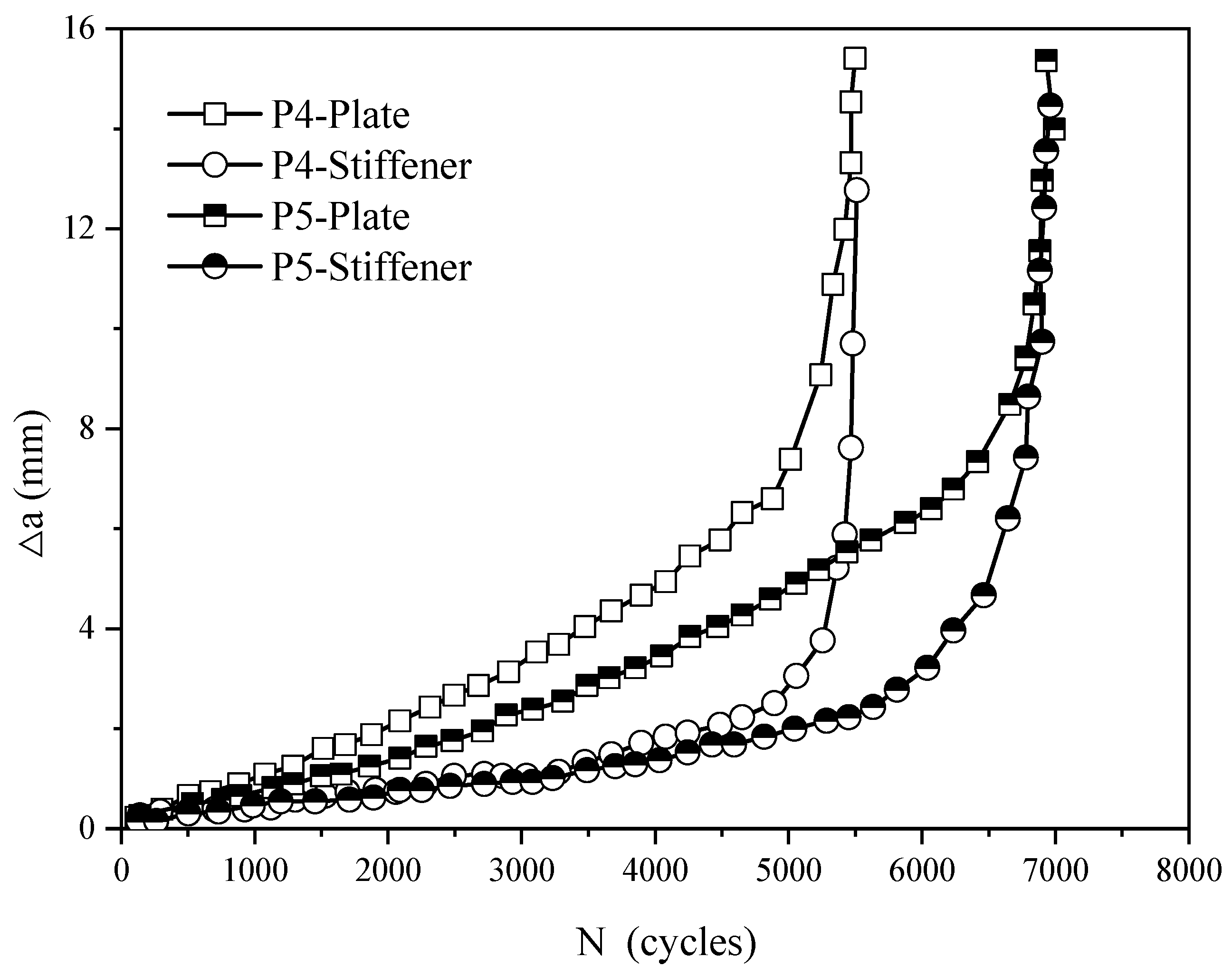
The variation in the crack growth increment Δa vs. cycles N of the stiffened plates with a central crack is shown in Figure 10. It can be seen that, both in the case of the flat plate and the stiffened plate specimens, the left and right crack growth lengths are almost identical during the crack propagation process, indicating good assembly accuracy of the fixtures in the experiment, thus the subsequent analysis does not separately discuss the left and right cracks. A comparison between the center-cracked flat plate specimen (P6) and the center-cracked stiffened plate specimen (P5) shows that the presence of stiffeners results in an increase of over 60% in the low-cycle fatigue crack growth life. The underlying mechanism is that the presence of the stiffener leads to a decrease in the primary driving force for crack growth, ΔCTOD, thereby reducing the crack growth rate of the stiffened plate specimen, as evidenced in Figure 11. A comparison between the P4 and P5 conditions indicates that an increase in the load amplitude significantly reduces the fatigue life of the center-cracked stiffened plate specimen. The entire crack growth process can be distinctly divided into two stages: stable propagation and unstable propagation, with the unstable propagation stage constituting a small proportion of the entire fracture life (about 10%). Therefore, the subsequent discussion primarily revolves around the stable propagation stage.
As depicted in Figure 12, the Δa-N curve for the plate and stiffener in the stiffened plate with central crack is displayed. It can be seen that, as the stress ratio increases, the crack growth rate decreases, as expected. Apparently, the fatigue life also increases as the stress ratio increases. It can be observed that, during the stable propagation stage, the crack growth rate on the stiffener is considerably smaller than that on the plate. Moreover, the crack length on the stiffener prior to unstable propagation is less than 3 mm, which is substantially smaller than the stiffener’s dimension (30 mm). Therefore, the following assumption is made in this study: during the stable propagation stage of the central crack in the stiffened plate specimen, the stiffener can almost maintain its integrity, and its constraining effect on the crack on the plate does not significantly diminish.
In Figure 13, the ΔCTOD data and crack propagation rate data for the stable propagation stage of the central-cracked stiffened plate are plotted. The correlation between da/dN and ΔCTOD is consistent with the material’s inherent crack propagation rate model, thereby validating the efficacy of the low-cycle fatigue crack growth test for the centrally cracked stiffened plate specimen.

4. Conclusions

This paper introduces a straightforward approach for determining the low-cycle fatigue crack growth rate in stiffened plate structures containing cracks using crack tip opening displacement as a key parameter. By analyzing the experimental and theoretical data on CTOD and crack growth rate, the following key findings can be summarized:
(1)
The fatigue crack growth life exhibits a strong correlation with CTOD, particularly under varying load levels. Equation (1) accurately defines the correlation between CTOD and the crack growth rate of EH-36 steel. This highlights the role of CTOD in describing the crack propagation characteristics of EH-36 steel subjected to low-cycle fatigue loading.
(2)
The presence of stiffeners imposes a significant constraint effect on the formation of cracks in the plate, leading to a notably smaller ΔCTOD for the stiffened plate specimen compared to the plain plate specimen, consequently reducing the crack propagation rate and increasing the low-cycle fatigue crack growth life.
(3)
The constraining effect of the stiffened plate on the crack is influenced by the crack tip position. When the crack tip is far from the stiffener, the ΔCTOD of the stiffened plate specimen continues to increase, indicating a minor constraining effect of the stiffener on the crack in the plain plate. As the crack tip moves closer to the stiffener, the constraining effect of the stiffener on the crack in the plain plate becomes significant. In the case of the specimen with a single-edged crack, ΔCTOD does not increase but decreases, and for the specimen with a center crack, ΔCTOD gradually approaches that of the plain plate specimen.
(4)
Further investigations are needed to explore the variation in the CTOD and crack growth rate under variable amplitude loading.

Author Contributions

Q.D., Study design and manuscript writing, G.X., Literature search and article translation, W.C., Making charts and data analysis. All authors have read and agreed to the published version of the manuscript.

Funding

This research was funded by the National Natural Science Foundation of China (grant no. 51909198).

Institutional Review Board Statement

Not applicable.

Informed Consent Statement

Not applicable.

Data Availability Statement

Due to the nature of this research, participants of this study did not agree for their data to be shared publicly, so supporting data are not available.

Conflicts of Interest

The authors declare no conflicts of interest.

References

  1. Dong, Q.; Xu, G.; Zhao, J.; Hu, Y. Experimental and numerical study on crack propagation of cracked plates under low cycle fatigue loads. J. Mar. Sci. Eng. 2023, 11, 1436. [Google Scholar] [CrossRef]
  2. Dong, Q.; Lu, X.; Xu, G. Experimental study on low-cycle fatigue characteristics of marine structural steel. J. Mar. Sci. Eng. 2024, 12, 651. [Google Scholar] [CrossRef]
  3. Gan, J.; Sun, D.; Deng, H.; Wang, Z.; Wang, X.; Yao, L.; Wu, W. Fatigue characteristics of designed T-type specimen under two-step repeating variable amplitude load with low-amplitude load below the fatigue limit. J. Mar. Sci. Eng. 2021, 9, 107. [Google Scholar] [CrossRef]
  4. Wang, Q.; Huber, N.; Liu, X.; Kashaev, N. On the analysis of plasticity induced crack closure in welded specimens: A mechanism controlled by the stress intensity factor resulting from residual stresses. Int. J. Fatigue 2022, 162, 106940. [Google Scholar] [CrossRef]
  5. Sistaninia, M.; Kolednik, O. A novel approach for determining the stress intensity factor for cracks in multilayered cantilevers. Eng. Fract. Mech. 2022, 266, 108386. [Google Scholar] [CrossRef]
  6. Nassiraei, H.; Rezadoost, P. Stress concentration factors in tubular T-joints reinforced with external ring under in-plane bending moment. Ocean. Eng. 2022, 266, 112551. [Google Scholar] [CrossRef]
  7. Nassiraei, H.; Rezadoost, P. Probabilistic analysis of the SCFs in tubular T/Y-joints reinforced with FRP under axial, in-plane bending, and out-of-plane bending loads. Structures 2022, 35, 1078–1097. [Google Scholar] [CrossRef]
  8. Nassiraei, H.; Rezadoost, P. Stress concentration factors in tubular T/Y-connections reinforced with FRP under in-plane bending load. Mar. Struct. 2021, 76, 102871. [Google Scholar] [CrossRef]
  9. Nassiraei, H.; Rezadoost, P. Static capacity of tubular X-joints reinforced with fiber reinforced polymer subjected to compressive load. Eng. Struct. 2021, 236, 112041. [Google Scholar] [CrossRef]
  10. Nassiraei, H.; Rezadoost, P. Stress concentration factors in tubular T/Y-joints strengthened with FRP subjected to compressive load in offshore structures. Int. J. Fatigue 2020, 140, 105719. [Google Scholar] [CrossRef]
  11. Dong, Q.; Yang, P.; Xu, G. Low cycle fatigue crack growth analysis by CTOD under variable amplitude loading for AH32 steel. Mar. Struct. 2019, 63, 257–268. [Google Scholar] [CrossRef]
  12. Dowling, N.E. Geometry effects and the J-integral approach to elastic-plastic fatigue crack growth. In Cracks and Fracture; Swedlow, J., Williams, M., Eds.; ASTM STP 601; American Society for Testing and Materials: Philadelphia, PA, USA, 1976; pp. 19–32. [Google Scholar]
  13. Gonzales, G.L.G.; González, J.A.O.; Antunes, F.V.; Neto, D.M.; Díaz, F.A. Experimental determination of the reversed plastic zone around fatigue crack using digital image correlation. Theor. Appl. Fract. Mech. 2023, 125, 103901. [Google Scholar] [CrossRef]
  14. Dunham, F.W. Fatigue Testing of Large-Scale Models of Submarine Structural Details. Mar. Technol. SNAME News 1965, 2, 299–307. [Google Scholar] [CrossRef]
  15. Chen, L.; Chen, X. The low cycle fatigue tests on submarine structures. Ship Sci. Technol. 1991, 2, 19–20. [Google Scholar]
  16. Li, C. Research on low cycle fatigue properties of several types of steel for submarine pressure shell. Dev. Appl. Mater. 1986, 12, 28–37. [Google Scholar]
  17. Liu, Y.; Zhu, X.; Huang, X. Experimental research on low frequency fatigue crack propagation rate of 921A hull steel structure. J. Nav. Univ. Eng. 2008, 20, 69–74. [Google Scholar]
  18. Jandejsek, I.; Gajdoš, L.; Šperl, M.; Vavřík, D. Analysis of standard fracture toughness test based on digital image correlation data. Eng. Fract. Mech. 2017, 182, 607–620. [Google Scholar] [CrossRef]
  19. Zhang, W.; Liu, Y. Plastic zone size estimation under cyclic loadings using in situ optical microscopy fatigue testing. Fatigue Fract. Eng. Mater. Struct. 2011, 34, 717–727. [Google Scholar] [CrossRef]
  20. Vasco-Olmo, J.M.; Díaz, F.A.; Antunes, F.V.; James, M.N. Characterization of fatigue crack growth using digital image correlation measurements of plastic CTOD. Theor. Appl. Fract. Mech. 2019, 101, 332–341. [Google Scholar] [CrossRef]
  21. Belytschko, T.; Black, T. Elastic crack growth in finite elements with minimal remeshing. Int. J. Numer. Methods Eng. 1999, 45, 601–620. [Google Scholar] [CrossRef]
  22. Melenk, J.M.; Babuška, I. The partition of unity finite element method: Basic theory and applications. Comput. Methods Appl. Mech. 1996, 139, 289–314. [Google Scholar] [CrossRef]
  23. He, L.; Liu, Z.; Gu, J.; Wang, J.; Men, K. Fatigue crack propagation path and life prediction based on XFEM. J. Northwestern Polytech. Univ. 2019, 37, 737–743. [Google Scholar] [CrossRef]
  24. Tu, W.; Yue, J.; Xie, H.; Tang, W. Fatigue crack propagation behavior of high-strength steel under variable amplitude loading. Eng. Fract. Mech. 2021, 247, 107642. [Google Scholar] [CrossRef]
  25. Huang, X.; Zhang, X.; Bai, G.; Xu, W.; Wang, H. Residual strength analysis of thin-walled structures with multiple site damage based on crack tip opening angle method. J. Shanghai Jiao Tong Univ. 2013, 47, 519–524+531. [Google Scholar]
  26. Hwang, J.H.; Kim, H.T.; Kim, Y.J.; Nam, H.S.; Kim, J.W. Crack tip fields at crack initiation and growth under monotonic and large amplitude cyclic loading: Experimental and FE analyses. Int. J. Fatigue 2020, 141, 105889. [Google Scholar] [CrossRef]
  27. Xiong, K.; Deng, J.; Pei, Z.; Yang, P.; Dong, Q. Analysis of accumulative plasticity and fracture behavior of hull cracked plates subjected to biaxial low-cycle fatigue loading. J. Ship Mech. 2022, 26, 113–124. [Google Scholar]
  28. Wei, X. Fatigue Reliability Analysis of Ship Stiffened Panel Structure Subjected to Multiple Cracks. Master’s Thesis, Harbin Engineering University, Harbin, China, 2017. [Google Scholar]
  29. Soares, C.G.; Garbatov, Y.; Safety, S. Fatigue reliability of the ship hull girder accounting for inspection and repair. Reliab. Eng. 1996, 51, 341–351. [Google Scholar] [CrossRef]
  30. Duncheva, G.; Maximov, J.; Ganev, N.; Ivanova, M. Fatigue life enhancement of welded stiffened S355 steel plates with noncircular openings. J. Constr. Steel Res. 2015, 112, 93–107. [Google Scholar] [CrossRef]
  31. Lei, J.; Yue, J.; Xu, Z.; Fang, X.; Liu, H. Theoretical and Experimental Analysis on Low-Cycle Fatigue Crack Initiation for High Strength Steel Stiffened Plates. In Proceedings of the ASME 2022 41st International Conference on Ocean, Offshore and Arctic Engineering, Hamburg, Germany, 5–10 June 2022. [Google Scholar]
  32. Dexter, R.J.; Pilarski, P.J. Crack propagation in welded stiffened panels. J. Constr. Steel Res. 2002, 58, 1081–1102. [Google Scholar] [CrossRef]
  33. Jiang, W.; Yang, P. Experimental studies on crack propagation and accumulative mean strain of cracked stiffened plates under low-cycle fatigue loads. Ocean. Eng. 2020, 214, 107744. [Google Scholar] [CrossRef]
  34. Song, Y.; Yang, P.; Hu, K.; Jiang, W.; Zhang, G. Study of low-cycle fatigue crack growth behavior of central-cracked stiffened plates. Ocean. Eng. 2021, 241, 110083. [Google Scholar] [CrossRef]
  35. Dong, Q.; Yang, P.; Deng, J.L.; Wang, D. The theoretical and numerical research on CTOD for ship plate under cyclic loading considering accumulative plastic strain. J. Ship Mech. 2015, 19, 1507–1516. [Google Scholar]
  36. Deng, J.; Yang, P.; Dong, Q.; Wang, D. Research on CTOD for low cycle fatigue analysis of central through cracked plates considering accumulative plastic strain. Eng. Fract. Mech. 2016, 154, 128–139. [Google Scholar] [CrossRef]
  37. Dong, Q.; Yang, P.; Xu, G.; Deng, J.L. Mechanisms and modeling of low cycle fatigue crack propagation in a pressure vessel steel Q345. Int. J. Fatigue 2016, 89, 2–10. [Google Scholar] [CrossRef]
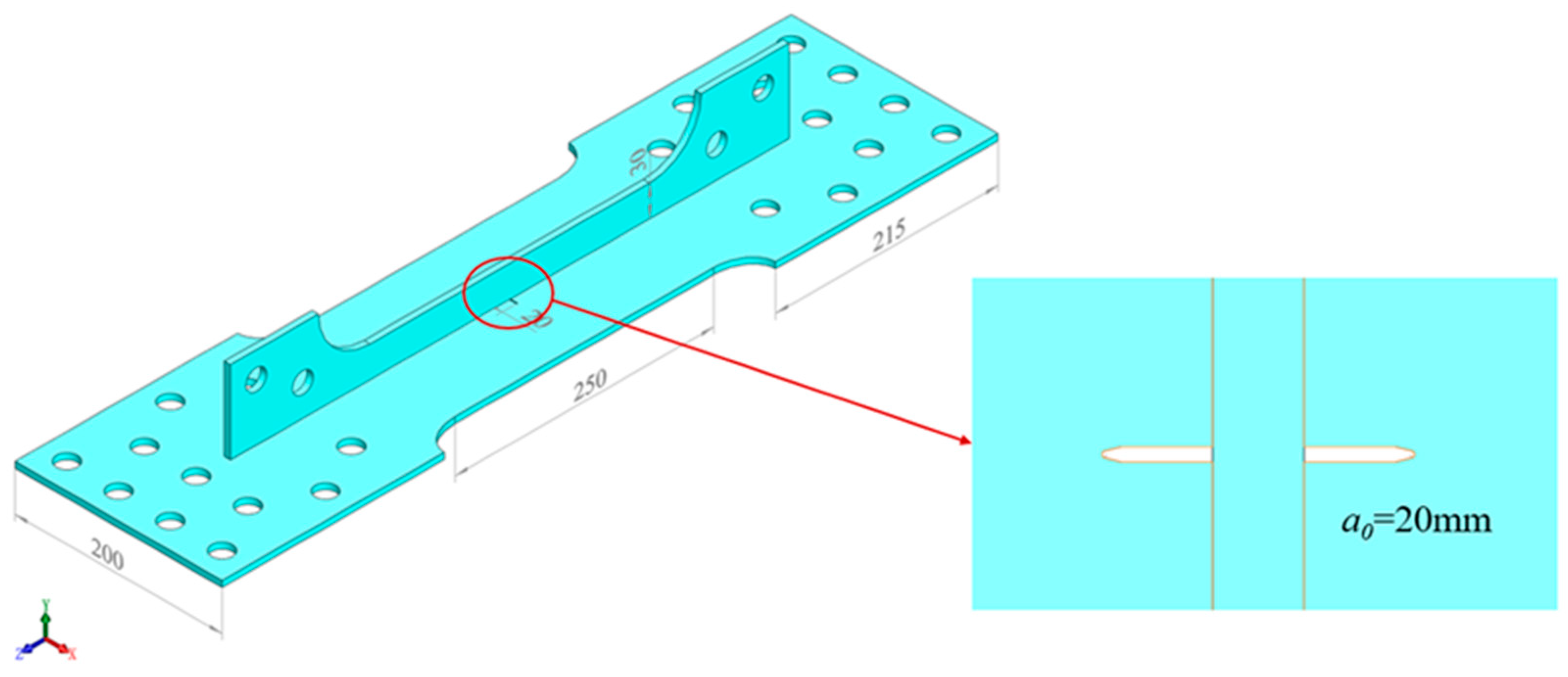
Figure 1. The geometry and dimensions of stiffened plate with central crack.
Jmse 12 01365 g001
Figure 2. The geometry and dimensions of stiffened plate with single-edge crack.
Jmse 12 01365 g002
Figure 3. The low-cycle fatigue crack growth tests of stiffened plates.
Jmse 12 01365 g003
Figure 4. Measuring crack length and CTOD using DIC.
Jmse 12 01365 g004
Figure 5. The effective plastic strain distribution of stiffened plate.
Jmse 12 01365 g005
Figure 6. The curve of Δa-N for stiffened plates with single-edge crack.
Jmse 12 01365 g006
Figure 7. The curve of crack length for stiffened plates with single-edge crack.
Jmse 12 01365 g007
Figure 8. The curve of CTOD for stiffened plates with single-edge crack.
Jmse 12 01365 g008
Figure 9. The curve of crack growth rate for stiffened plates with single-edge crack.
Jmse 12 01365 g009
Figure 10. The curve of Δa-N for stiffened plates with central crack.
Jmse 12 01365 g010
Figure 11. The curve of CTOD for stiffened plates with central crack.
Jmse 12 01365 g011
Figure 12. The curve of Δa-N for plate and stiffener of stiffened plates with central crack.
Jmse 12 01365 g012
Figure 13. The curve of crack growth rate for stiffened plates with central crack.
Jmse 12 01365 g013
Table 1. Mechanical property parameters of EH36 steel.
Elastic Modulus/GPaPoisson’s RatioYield Stress/MPaUltimate Tensile Strength/MPa
2060.3434.94548.91
Table 2. The loading cases.
Specimen NumberPmax/kNR = Pmin/PmaxNominal Stress/MPaCrack LocationStiffener Height
P184.24−1120single-edge crack30 mm
P290.72−1130single-edge crack30 mm
P397.20−1140single-edge crack30 mm
P4384.000.031280central crack30 mm
P5420.000.2300central crack30 mm
P6420.000.2300central crack0 mm
Disclaimer/Publisher’s Note: The statements, opinions and data contained in all publications are solely those of the individual author(s) and contributor(s) and not of MDPI and/or the editor(s). MDPI and/or the editor(s) disclaim responsibility for any injury to people or property resulting from any ideas, methods, instructions or products referred to in the content.