Abstract
With the rapid development of marine engineering in recent years, offshore operations have become increasingly common, making wave compensation platforms crucial for safe operations at sea. This paper presents a pendulum-type wave compensation platform specifically designed for wave compensation applications. The main components of this wave compensation platform include a chassis, support base, hydraulic cylinders, telescopic rods, upper platform, three sets of balancing mechanisms, three sets of tilt angle sensors, and a control system. Firstly, to thoroughly understand the compensatory motion of the pendulum-type three-degree-of-freedom wave compensation platform, kinematic analysis of the entire system was conducted, and the motion inverse solution curves of the mechanism were obtained through simulation using motion simulation software. Secondly, to enhance the compensatory response performance of the platform, a fuzzy PID control algorithm was employed to control the system and achieve attitude control of the platform. Finally, through control system simulation, compared to PID control, fuzzy PID reduces system response delay and successfully meets the expected technical requirements and application needs.
1. Introduction
In recent years, with the rapid development of the ocean engineering field, higher demands have been placed on the stability and reliability of offshore operations. As a result, wave compensation platforms have emerged as an effective means of structural control. The design of wave compensation platforms aims to offset structural vibrations caused by waves through intelligent control systems, thereby enhancing the stability and safety of offshore structures. Various wave compensation structures and control methods have emerged in recent years.
In the structural design section, Han Bo et al. [1] designed a parallel airborne stabilization platform (ASP) based on a 3-UPS/S mechanism and proposed a finite step integration method (FSI) to analyze the kinematic characteristics of general parallel mechanisms. Addressing the issues of system coupling and high payload-to-mass ratio, Liang Chao et al. [2] designed a super stable satellite platform (SUSP), determined the dynamic equilibrium and vibration transfer function of SUSP, and decoupled the multi-input multi-output (MIMO) system into six single-input single-output (SISO) subsystems. Tang Gang et al. [3] proposed an improved six-degree-of-freedom hybrid serial-parallel platform (HSPP), which has advantages in workspace and decoupling over the Stewart platform. In the automotive field, Udomsap Tossaporn et al. [4] designed a 3-PRS parallel robot for platform stabilization, used to stabilize visual equipment on the top of a vehicle. Guang Can Lu [5] introduced a 3UPU/PU parallel platform capable of one linear and two rotational motions (3-DOF) for automatic wave compensation of ship deck equipment. Simulation calculations provided velocity, acceleration, and force curves, laying the foundation for further dynamic analysis and control. Zhao Yanzhi et al. [6] proposed a new control scheme for the non-inertial six-rotational universal spherical (6-RUS) parallel mechanism in stabilization platforms. They used screw theory to establish the kinematic model, simplified the dynamic modeling, and proposed a sliding mode control strategy with an extended state observer to address uncertainties. Min Xu [7] proposed a method called “Transfer Network”, which combines fine-tuning and backpropagation neural networks to improve the pose accuracy of three-degree-of-freedom parallel robots.
In terms of control methods, Song Jiangpeng et al. [8] proposed a coarse-fine dual-level control system to address the robustness issues of nonlinear and control algorithms. They used an adaptive model to compensate for parameter changes and nonlinearity, and designed a robust H∞ control scheme to enhance the system’s robustness against model uncertainties. Lin Enfan et al. [9] proposed a control system design method based on Linear Active Disturbance Rejection Control (LADRC), achieving anti-saturation and anti-noise design by studying PID controllers and ADRC control methods. Tianlei Fu et al. [10] introduced a pre-activation anti-saturation method based on LADRC to address the impact of acceleration saturation on actuators in small inertial stabilization platforms (MISP). Dong Mei et al. [11] proposed a control scheme based on the ADRC inverse estimation algorithm, developing an inverse Extended State Observer (ESO) through ESO characteristics for reverse estimation of unmodeled and extended states of the platform system. Azarskov Valerii et al. [12] discussed the design of the control system for an airborne inertial stabilization platform (ISP) on aircraft, improving the system’s stability and accuracy by introducing feedforward disturbance gain in the PI feedback control law. Lei Xusheng et al. [13] proposed a composite control method combining a nonlinear dynamic model based on geographic coordinates, an adaptive extended state observer (AESO), and adaptive backstepping integral sliding mode control (SMC). Chen Weixing et al. [14] proposed a triple-loop control strategy based on ADRC for an electrically driven shipboard Stewart platform. Simulation results showed that this control strategy performed well in power reduction, decoupled control, and disturbance rejection. Yu Wen et al. [15] studied the dynamic characteristics of a shipboard Stewart platform in compensating for the induced six-degree-of-freedom motion of a ship. They derived a non-singular terminal sliding mode control law and combined it with time-delay estimation and Kalman filtering adaptive estimation methods to achieve robust control of platform motion. Feng Wenlong et al. [16] proposed an improved global fast terminal sliding mode control method based on neural networks (NNFTSMC) for designing the dynamic control system of a three-axis stabilization platform. Chen Xin et al. [17] proposed an improved differential evolution adaptive fuzzy PID control (IDEAFC) algorithm to improve the stability accuracy of a platform-type gravimeter. Zhou Zhanmin et al. [18] introduced an MIMO (multi-input multi-output) fuzzy sliding mode control method for a three-axis inertial stabilization platform.
In terms of applications, Jianjun Wang et al. [19] proposed a method to compensate for the attitude fluctuations of helicopter-borne laser scanning. Experimental results showed that the attitude compensation prototype could effectively reduce the impact of attitude fluctuations on point cloud products. Chen Weixing et al. [20] proposed a modal space control strategy for high-precision compensation control of a shipboard Stewart platform, particularly considering the effects of gangway heavy loads and gangway vibrations on dynamic performance. Zhan Yong et al. [21] designed a wave compensation system based on a 3-SPR parallel platform for ships with dynamic positioning systems, capable of compensating for heave, roll, and pitch motions of the ship in sea state 4. Cai Yunfei et al. [22,23] proposed a sliding mode control scheme, using the Kane method to establish a dynamic model that considers the impact of ship motion. To improve control performance, a novel velocity feedforward compensator was introduced, and a sliding mode backstepping controller based on command filtering was developed. Additionally, an improved control method was proposed, utilizing a multi-degree-of-freedom velocity feedforward compensator to design an improved motion controller.
To provide a stable working platform for offshore operations, this study proposes a novel wave compensation device—the pendulum-type wave compensation platform. Firstly, a detailed description of the platform’s overall structure was provided, specifying its degrees of freedom. Subsequently, kinematic simulations of the structure were conducted to obtain inverse solution curves. The design of the platform’s control system was then thoroughly elaborated. During the control system design process, control system simulations were employed for verification. Comparative analysis against traditional PID control demonstrated the significant advantages of fuzzy PID control in terms of response performance. Specifically, the fuzzy PID control system effectively compensates for wave fluctuations with rapid and accurate responses, reducing response time and system impact to achieve smoother platform motion. Through these simulations and comparative analyses, results indicate that fuzzy PID control not only meets technical requirements but also adapts well to practical application needs, enhancing system dynamic response and stability. In summary, this study successfully designs and validates the feasibility and superiority of the pendulum-type wave compensation platform, providing a more stable and reliable working platform for offshore operations with significant practical application value.
2. Structural Analysis
2.1. Structural Description
This paper proposes a swing-type wave compensation platform (RCP). The RCP mechanism is a series-parallel hybrid structure with simple construction and high stability. The specific structure, as shown in Figure 1, mainly includes three UPRP chains and one UP chain. Each UPRP chain consists of a horizontal Hooke joint, an electric cylinder, a hinged seat slider, and a sliding track. The UP chain includes a cross joint and an electric cylinder.
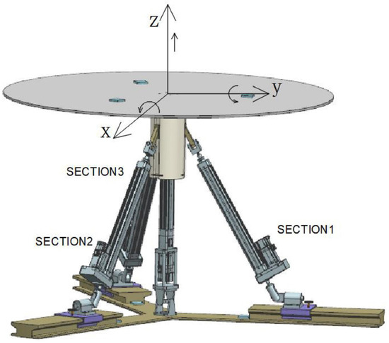
Figure 1.
Swing-type wave compensation platform structure.
To achieve the operation of the overall mechanism, the structure also includes a herringbone base and an upper disc. The horizontal Hooke joint is fixed on the slider of the herringbone base by bolts, and the position of the electric cylinder is adjusted by tightening bolts to adapt to different application scenarios. Since the electric cylinder is placed obliquely and a standard cross joint does not have enough load capacity or stability when the electric cylinder extends and retracts, the horizontal Hooke joint can effectively bear the load and provide stability. This greatly enhances the stability during the compensation process.
2.2. Degree of Freedom Calculation
Due to the hybrid nature of this mechanism, its degrees of freedom are calculated by dividing it into two sub-mechanisms: a parallel structure and a series structure. After calculating the degrees of freedom for each sub-mechanism separately and summing them up, the degrees of freedom for the series-connected upper platform are found to be 1. Using the modified G-K formula for degrees of freedom calculation of the RCP series-parallel hybrid structure yields
In the equation, represents the total degrees of freedom of the entire mechanism, denotes the order, indicates the number of active components, signifies the number of kinematic pairs, denotes the count of degrees of freedom for the ith kinematic pair, and represents the number of overconstraints.
From the above equation, the degrees of freedom of the mechanism can be determined as
In summary, the degrees of freedom of this hybrid mechanism are 3, namely rotation about the X-axis, rotation about the Y-axis, and vertical translation along the Z-axis.
2.3. Kinematic Analysis
As shown in Figure 1, this platform can perform heave motion along the Z-axis and rotational motion around the X and Y axes. The heave motion along the Z-axis is achieved by the extension and retraction of the central electric cylinder. The rotational motions around the X and Y axes are achieved through the coordinated interactions of SECTION1, SECTION2, and SECTION3 along the respective axes. Figure 2 shows the working diagram of the compensation platform on a ship. This platform is placed at the ship’s center of gravity, establishing an external coordinate system at the ship’s center of gravity and an internal coordinate system at the center of the upper platform of the compensation platform. When the ship experiences roll, pitch, and heave motions, the structure compensates in three directions, ensuring that the upper platform of the compensation platform remains relatively stationary.
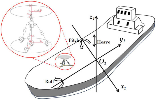
Figure 2.
Working diagram of the compensation platform on the ship.
As shown in Figure 2, a fixed coordinate system is established on the stationary platform, and a reference coordinate system is established on the moving platform, through rotation about the X-axis, rotation about the Y-axis, and translation along the Z-axis to obtain the coordinate system , where h changes with the series mechanism. Hence, the directed distances from the axis to the axis and from the axis to the axis are both h; the directed angle between the axis and the axis is ; and the directed angle between the axis and the axis is . Therefore, the homogeneous coordinate transformation matrix from coordinate system to coordinate system can be expressed as
Expand the above formula, and we can get
Therefore, the D-H matrix from coordinate system to coordinate system is
2.4. Kinematics Simulation Analysis
To verify the rationality of the structural design and ensure the stability of the platform during the compensation process, simulation analysis was conducted using motion simulation software. First, the designed model was simplified in UG11.0 (Unigraphics NX), then saved and exported as an .x_t file. The exported .x_t file was then opened in motion simulation software, as shown in Figure 3.
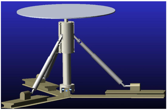
Figure 3.
Motion simulation diagram.
According to the design requirements, various motion pairs were added at each connection point. In motion simulation software, drives are by default considered constraints, leading to redundancy issues. To solve this problem, motion pairs were replaced with constraints, using multiple constraints simultaneously to achieve the effect of a motion pair. The constraints of motion pairs on degrees of freedom in motion simulation software are shown in Table 1, The horizontal Hooke joint in this structure is shown in Figure 4. The rotary joint connecting the horizontal Hooke joint to the base is shown in Figure 5a. By replacing the rotary joint with a point-plane constraint, a collinear constraint, and a perpendicular constraint, as shown in Figure 5b, the redundancy issue can be effectively resolved.

Table 1.
The relationship between degrees of freedom constraints imposed by motion pairs.
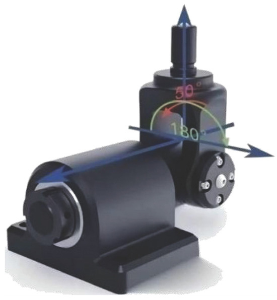
Figure 4.
Horizontal Hooke joint.
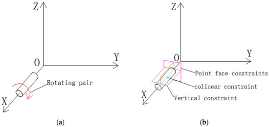
Figure 5.
Rotational pair and combination constraint relationship diagram: (a) rotary pair; (b) point-plane, collinear, and perpendicular combination constraints.
After adding the kinematic pairs at each connection point, we proceed to verify the motion around the X-axis, Y-axis, and along the Z-axis. The rotational motions around the X-axis and Y-axis are achieved through the coordinated interactions of SECTION1, SECTION2, and SECTION3. The simulations include single-degree-of-freedom motion compensation of 20 degrees around the X-axis, single-degree-of-freedom motion compensation of 20 degrees around the Y-axis, coupled motion compensation of 20 degrees around both the X-axis and Y-axis, and single-degree-of-freedom motion compensation of 50 mm along the Z-axis. The simulations provide the extension and retraction curves of electric cylinders A, B, C, and D for SECTION1, SECTION2, and SECTION3 in different scenarios. These characteristics are shown in Figure 6, Figure 7, Figure 8 and Figure 9, respectively.
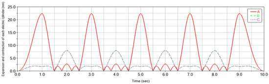
Figure 6.
Inverse kinematics curve for single degree of freedom motion about the X-axis.
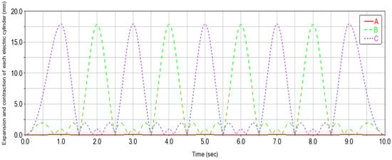
Figure 7.
Inverse kinematics curve for single degree of freedom motion about the Y-axis.
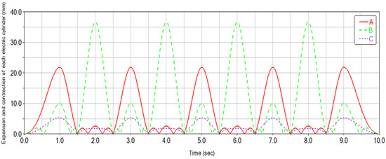
Figure 8.
Inverse kinematics curve for coupled motion around the X and Y axes.
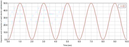
Figure 9.
Inverse kinematics curve for single degree of freedom motion along the Z-axis.
Through kinematic analysis in motion simulation software, the coordinated action of four electric cylinders can clearly demonstrate achievement of single-degree-of-freedom and coupled motions around the X, Y, and Z axes. These cylinders serve not only as motion actuators but also ensure smooth operation through precise coordination and compensation processes. This integrated motion control approach significantly enhances system accuracy and reliability, providing a robust foundation for executing complex motion tasks.
3. Control System Design
3.1. Controller Design
This structure is primarily used in the field of wave compensation. In harsh marine environments, various uncertainties can lead to inaccurate platform compensation and untimely response. Since fuzzy PID control can achieve efficient control in complex and nonlinear systems, the system can be controlled using a fuzzy PID controller. This enables the entire structure to achieve efficient and precise control in complex and harsh environments. The specific control scheme is shown in Figure 10.
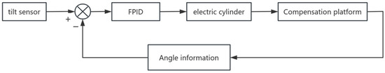
Figure 10.
Control system block diagram.
3.2. Fuzzy PID Controller
The fuzzy PID controller is based on the traditional PID controller and adjusts the , , and parameters of the PID controller in real time according to the error. The , , and parameters are changed online in real time to correspond to the changes in the fuzzy PID controller, thereby achieving effective control of the nonlinear time-varying system. Fuzzification involves the mapping between the value range of the compensation platform input error and the corresponding domain.
The fuzzy PID controller of this compensation platform has two inputs and three outputs. The input of the fuzzy controller is the deviation and the relative deviation change rate , and the output is the PID controller parameter correction , , and . When the control system is running, the inputs and are fuzzified, fuzzy reasoning, and defuzzified to obtain the online correction , , and , which are input into the PID controller, respectively, so that the compensation platform can adjust , , and in real time in response to different wave motion states to ensure that the system reaches the best response state and the compensation platform has a good compensation effect. The fuzzy PID control principle of the swaying wave compensation platform system is shown in Figure 11.
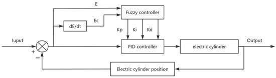
Figure 11.
Fuzzy adaptive PID block diagram.
Fuzzy processing is a process that first normalizes the input quantity according to the membership function of the fuzzy set, then discretizes the normalized input quantity, and finally converts it into the corresponding variable value on the domain and determines its membership. The fuzzy rules adopt the standardized design created by Mamdani, define the range of inputs and and outputs , , and as the domain [−1, 1] on the fuzzy set, and select the seven-level fuzzy subset , where N represents negative, P represents positive, B represents large, M represents medium, S represents small, and Z represents 0. The input membership function adopts Gaussian membership function, and the output membership function adopts triangular membership function. The membership function of input quantity is shown in Figure 12, and the membership function of output quantity is shown in Figure 13.
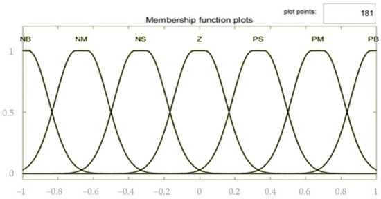
Figure 12.
Membership function of input E.
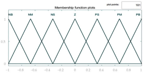
Figure 13.
Membership function of the output .
The second is the establishment of fuzzy rules. In order to obtain the best control performance, the fuzzy rules, membership functions, and proportional factors are adjusted. According to the motion characteristics of the swing-type compensation platform, fuzzy statements are selected to establish fuzzy control rule tables for , , and outputs, as shown in Table 2, Table 3, and Table 4, respectively. According to the corresponding rule tables, the if input and then output are used to complete the rule configuration.
Table 2.
rule table.
Table 3.
rule table.
Table 4.
rule table.
4. Simulation Results and Analysis
The compensation angle caused by waves often varies randomly over time. To better simulate the system’s response to waves, a varying compensation angle function was implemented using a function block in the control system simulation software. The specific function is shown in the figure below.
The input of waves is mainly based on wave height and frequency. The compensation platform of the sway compensation platform is in the three directions of roll, pitch, and heave. According to the relationship between the wave input and the platform response, the movement in a single direction can be expressed by the second-order transfer function. Assuming the wave input and the platform response , the transfer function can be obtained as follows:
where K is the system gain, representing the degree of influence of wave input on platform sway, is the damping ratio, representing the damping characteristics of the system, and is the natural frequency of the system. Using fuzzy PID control for the swing-type wave compensation platform, the current sway angle is , the angular velocity is , and the angular acceleration is .
If the system gain K = 1, damping ratio .7, natural frequency , then the transfer function is
After simplification,
First, fuzzy PID control is built in control system simulation software using fuzzy, where the , and parameters are first adjusted in PID using the PID tuner APP that comes with control system simulation software, and then the parameters of , , and are obtained by manual slight modifications. Secondly, a sinusoidal function simulating the change in wave motion is built, and the final control block diagram is shown in Figure 14. Finally, , , and in the fuzzy PID are obtained through trial and error and PID tuner APP.
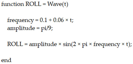
Figure 14.
Compensation Angle Variation Function.
From Figure 15, it can be observed that as the compensating platform experiences continuous wave fluctuations, the required compensation angles vary over time. In such scenarios, traditional PID control systems often exhibit delayed responses, leading to increased compensation errors. In contrast, fuzzy PID control demonstrates faster response speeds and superior compensation performance compared to standard PID control. Specifically, fuzzy PID control minimizes impacts during the compensation process, resulting in smoother wave responses and greater adaptability. See also Figure 16.
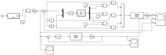
Figure 15.
Control simulation of the swing-type wave compensation platform.
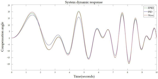
Figure 16.
System response state.
This improvement not only enables fuzzy PID control to effectively handle fluctuations in wave conditions but also significantly enhances the system’s dynamic response capabilities. When dealing with complex nonlinear systems, fuzzy PID control dynamically adjusts parameters in real-time, thus avoiding the sluggishness and overshoot issues associated with conventional PID control’s fixed parameters.
Therefore, fuzzy PID control exhibits superior dynamic response and adaptability in pendulum-type wave compensation platforms, ensuring smoother and more reliable system operations that effectively mitigate disturbances caused by waves. This underscores that adopting fuzzy PID control can notably enhance the performance of compensation platforms in practical applications, improving system stability and response speed.
5. Conclusions
This paper proposes a novel wave compensation device and control method to meet the increasing demands of offshore operations driven by the rapid development of marine engineering. The main components of this structure include a chassis, support base, hydraulic cylinders, telescopic rods, upper platform, three sets of balancing mechanisms, three sets of tilt angle sensors, and a control system.
Firstly, kinematic analysis of the pendulum-type three-degree-of-freedom wave compensation platform was conducted using motion simulation software to simulate motion and obtain inverse motion curves of the mechanism. These curves served as a theoretical basis for designing the control system, ensuring the platform achieves the intended three-degree-of-freedom motion.
Secondly, a fuzzy PID control algorithm was implemented to enhance the platform’s compensation response performance. Control system simulations demonstrated that fuzzy PID control significantly reduces system response delays, improving stability and precision. Compared to traditional PID control, fuzzy PID exhibits stronger robustness in handling nonlinearities and uncertainties, effectively addressing wave impacts in complex marine environments.
Lastly, the study confirms that the designed pendulum-type wave compensation platform control system successfully meets technical requirements and application needs. Fuzzy PID control not only enhances compensation performance but also increases system adaptability and robustness. In practical applications, this system effectively ensures safety and stability for offshore operations, providing reliable technical support for wave compensation in marine engineering. Future research could focus on further optimizing control strategies to enhance platform intelligence and adaptability.
Author Contributions
Conceptualization, Y.H.; software, Y.H.; resources, Y.H.; writing—original draft preparation, Y.H.; writing—review and editing, H.Z. and P.Z.; visualization, Y.H.; founding, P.Z.; supervision, G.T. All authors have read and agreed to the published version of the manuscript.
Funding
This research was supported in part by the National Natural Science Foundation of China (No. 51905557).
Institutional Review Board Statement
Not applicable.
Informed Consent Statement
Not applicable.
Data Availability Statement
The data and code that support the findings of this study are available on request from the second author.
Acknowledgments
The authors would like to thank the funding body for the grant.
Conflicts of Interest
The authors declare that there is no conflict of interest.
References
- Bo, H.; Yuan, J.; Wei, Y.; Yundou, X.; Jiantao, Y.; Yongsheng, Z. Kinematics characteristics analysis of a 3-UPS/S parallel airborne stabilized platform. Aerosp. Sci. Technol. 2023, 134, 108163. [Google Scholar]
- Chao, L.; Weipeng, L.; Hai, H.; Zhuokun, W. Decoupling design and control of a spaceborne ultra–stable platform for vibration isolation and precise steering. Sound Vib. 2023, 553, 117668. [Google Scholar]
- Gang, T.; Jinman, L.; Furong, L.; Weidong, Z.; Xiuzhong, X.; Baoheng, Y.; Christophe, C.; Xiong, H. A modified 6-DOF hybrid serial–parallel platform for ship wave compensation. Ocean Eng. 2023, 280, 114336. [Google Scholar]
- Tossaporn, U.; Sakda, C.; Siwat, L.; Teeranoot, C. Kinematics of platform stabilization using a 3-PRS parallel manipulator. Robomech J. 2023, 10, 8. [Google Scholar]
- Lu, G.C. Analysis of Kinematics and Dynamics of 3UPU/PU Parallel Platform Used in Automatic Wave Compensation. Adv. Mater. Res. 2014, 3593, 1061–1066. [Google Scholar] [CrossRef]
- Zhao, Y.; Yu, H.; Zhang, J.; Yang, J.; Zhao, T. Kinematics, dynamics and control of a stabilized platform with a 6-rus parallel mechanism. Int. J. Robot. Autom. 2017, 32, 283–290. [Google Scholar]
- Xu, M.; Tian, W.; Zhang, X. Kinematic Calibration for the 3-U P S/S Shipborne Stabilized Platform Based on Transfer Learning. Mar. Sci. Eng. 2024, 12, 275. [Google Scholar] [CrossRef]
- Song, J.P.; Zhou, D.; Sun, G.L.; Qi, Z.H. Robust control with compensation of adaptive model for dual-stage inertially stabilized platform. Cent. South Univ. 2018, 25, 2615–2625. [Google Scholar] [CrossRef]
- Lin, E.; Xu, J.; Wu, M.; He, H. Design of the LADRC control system for gravimetric stabilisation platforms. Phys. Conf. Ser. 2021, 2113, 012018. [Google Scholar]
- Fu, T.; Guan, L.; Gao, Y.; Qin, C. An Anti-Windup Method Based on an LADRC for Miniaturized Inertial Stabilized Platforms on Unmanned Vehicles in Marine Applications. Mar. Sci. Eng. 2024, 12, 616. [Google Scholar] [CrossRef]
- Mei, D.; Yu, Z.Q. Disturbance rejection control of airborne radar stabilized platform based on active disturbance rejection control inverse estimation algorithm. Assem. Autom. 2021, 41, 525–535. [Google Scholar] [CrossRef]
- Valerii, A.; Anatoly, T.; Olha, S. Design of Composite Feedback and Feedforward Control Law for Aircraft Inertially Stabilized Platforms. Int. J. Aerosp. Eng. 2020, 2020, 8853928. [Google Scholar]
- Lei, X.; Fu, F.; Wang, R. A High-Performance Compound Control Method for a Three-Axis Inertially Stabilized Platform under Multiple Disturbances. Symmetry 2022, 14, 1848. [Google Scholar] [CrossRef]
- Chen, W.; Wang, S.; Li, J.; Lin, C.; Yang, Y.; Ren, A.; Li, W.; Zhao, X.; Zhang, W.; Guo, W.; et al. An ADRC-based triple-loop control strategy of ship-mounted Stewart platform for six-DOF wave compensation. Mech. Mach. Theory 2023, 184, 105289. [Google Scholar]
- Wen, Y.; Li, W.; Zhou, S.; Gao, F.; Chen, W. Robust sliding mode control with adaptive gravity estimation of ship-borne Stewart platform for wave compensation. Appl. Ocean. Res. 2024, 148, 104004. [Google Scholar] [CrossRef]
- Feng, W.; Zhang, X. Controller Design for Three-Axis Stabilized Platform Using Adaptive Global Fast Terminal Sliding Mode Control with Non-Linear Differentiator. Energies 2021, 14, 6532. [Google Scholar] [CrossRef]
- Chen, X.; Bian, H.; He, H.; Li, F. An Improved Differential Evolution Adaptive Fuzzy PID Control Method for Gravity Measurement Stable Platform. Sensors 2023, 23, 3172. [Google Scholar] [CrossRef]
- Zhou, Z.; Zhang, B.; Mao, D. MIMO Fuzzy Sliding Mode Control for Three-Axis Inertially Stabilized Platform. Sensors 2019, 19, 1658. [Google Scholar] [CrossRef]
- Wang, J.; Xu, L.; Fan, Y.; Liu, X.; Tian, Z.; Wang, X.; Cheng, Y. A method for compensating platform attitude fluctuation for helicopter-borne LiDAR: Performance and effectiveness. Measurement 2018, 125, 37–47. [Google Scholar] [CrossRef]
- Chen, W.; Yu, W.; Tong, X.; Lin, C.; Li, J.; Wang, S.; Xie, W.; Mao, L.; Chao, Z.X.; Zhang, W.; et al. Dynamics modeling and modal space control strategy of ship-borne Stewart platform for wave compensation. J. Mech. Robot. 2023, 15, 041015. [Google Scholar]
- Zhan, Y.; Tian, H.; Xu, J.; Wu, S.; Fu, J. A Novel Three-SPR Parallel Platform for Vessel Wave Compensation. J. Mar. Sci. Eng. 2020, 8, 1013. [Google Scholar] [CrossRef]
- Cai, Y.; Zheng, S.; Liu, W.; Qu, Z.; Zhu, J.; Han, J. Sliding-mode control of ship-mounted Stewart platforms for wave compensation using velocity feedforward. Ocean Eng. 2021, 236, 109477. [Google Scholar]
- Cai, Y.; Zheng, S.; Liu, W.; Qu, Z.; Han, J. Model Analysis and Modified Control Method of Ship-Mounted Stewart Platforms for Wave Compensation. IEEE Access 2021, 9, 4505–4517. [Google Scholar]
Disclaimer/Publisher’s Note: The statements, opinions and data contained in all publications are solely those of the individual author(s) and contributor(s) and not of MDPI and/or the editor(s). MDPI and/or the editor(s) disclaim responsibility for any injury to people or property resulting from any ideas, methods, instructions or products referred to in the content. |
© 2024 by the authors. Licensee MDPI, Basel, Switzerland. This article is an open access article distributed under the terms and conditions of the Creative Commons Attribution (CC BY) license (https://creativecommons.org/licenses/by/4.0/).