Article

Experimental Investigation on the Impact of Sand Particle Size on the Jet Pump Wall Surface Erosion

1
School of Mechanical Engineering, Zhejiang University of Water Resources and Electric Power, Hangzhou 310018, China
2
Zhejiang Hangke Technology Incorporated Company, Hangzhou 311217, China
3
College of Metrology Measurement and Instrument, China Jiliang University, Hangzhou 310018, China
4
College of Energy Engineering, Zhejiang University, Hangzhou 310027, China
*
Author to whom correspondence should be addressed.
J. Mar. Sci. Eng. 2024, 12(8), 1390; https://doi.org/10.3390/jmse12081390
Submission received: 15 July 2024 / Revised: 6 August 2024 / Accepted: 11 August 2024 / Published: 14 August 2024
(This article belongs to the Section Ocean Engineering)

Abstract

:
Silt removal is crucial for maintaining navigable waterways in harbors. Jet pumps, without moving parts, are highly suitable for underwater operations such as channel dredging in port environments. Despite their structural advantages in slurry handling, the prolonged transport of solid–liquid two-phase flows can lead to wear on the wall materials, resulting in decreased efficiency and potential pump failure. The wear characteristics of the jet pump walls due to sand particles of varying grain sizes were experimentally investigated. The characteristic of the sands having a higher distribution above the axis as they enter the jet pump was captured by a high-speed camera. The experiment recorded the variations in mass loss at different sections of the jet pump over a period of 120 h, identifying that backflow within the throat region is a significant contributor to wall wear. Scanning electron microscopy was employed to examine the microstructure of the abraded pump surfaces. It was found that there are noticeable differences in the surface wear microstructure across various pump areas, and that particles of different grain sizes result in distinct wear patterns on the pump surfaces. The underlying causes of this phenomenon were discussed from the perspective of particle motion.

1. Introduction

The accretion of silt in navigation channels reduces the depth, directly impacting the draft of vessels and limiting the passage of large ships, potentially leading to groundings and hull damage. Consequently, silt removal is critical for ensuring the navigability of harbor waterways. Among various silt removal equipment, jet pumps represent an efficient and economical option for slurry transportation in dredging operations [1]. Compared to other pump types, jet pumps feature a simple design without internal moving parts, offering high reliability [2]. The absence of rotating elements in jet pumps makes them less prone to damage when conveying abrasive materials such as sand and gravel present in silt [3]. This allows jet pumps to operate continuously under harsh conditions without frequent shutdowns for maintenance, a critical factor in maintaining the consistency and productivity of dredging activities [4].
Although the unobstructed flow path of jet pumps minimizes the direct impact of solid particles on the wall material, the fluid dynamics within the pump influence the particles’ movement, preventing them from strictly adhering to axial flow [5]. Radial motion still occurs, which introduces a risk of particle-induced erosion on the pump’s wall material. Prolonged exposure to particle erosion can lead to material loss on the inner surfaces of the pump, reduced efficiency, and potentially, pump damage and system failure [6]. Therefore, investigating the wear characteristics of jet pump walls under the impact of solid particles holds significant importance.
It is evident that the flow within a jet pump belongs to the category of coaxially confined jets, where two streams mix and flow axially. The radial expansion of the jet is restricted by the pump wall. Based on the development of primary and secondary flows, the internal flow in a jet pump can be divided into four regions: the potential core region, transition zone, recirculation zone, and pipe flow region. In the potential core region, the potential core zones of both the primary and secondary flows decrease along the flow direction while the boundary layer near the wall and the internal shear layer gradually increase and merge [7]. After merging, the potential core zone of the secondary flow disappears. Within the transition zone, the potential core of the primary flow also gradually disappears along the flow direction, leading to complete mixing of the primary and secondary flows, whereupon the entrained fluid is fully consumed [8]. When the secondary flow cannot meet the entrainment demand of the primary flow, a recirculation zone forms near the wall. Fully mixed fluids then evolve into pipe flow, which eventually exits the jet pump through the pipe flow region [9]. Early research on the internal flow of jet pumps was constrained by limitations in computational resources and foundational scientific research conditions, primarily focusing on theoretical derivations. Zhdanov et al. [10] found through experiments that the length of the potential core and the expansion rate of the jet are influenced by the nozzle diameter and inlet flow conditions. Vortex shedding at the nozzle accelerates the reduction in the potential core and speeds up the mixing of the working fluid with the entrained fluid, causing the mixed fluid to enter the pipe flow stage earlier. In recent years, with the development of computer technology, numerical computation has become the mainstream technique for studying internal flows in jet pumps. It uses numerical simulation software to solve control equations for the internal flow, allowing for statistical analysis of parameters and fluctuations at all positions within the jet pump [11]. This approach reduces the experimental process and lowers research costs [12]. Xu et al. [13] proposed a global optimization method for the design of annular jet pumps that combines Computational Fluid Dynamics (CFD), Kriging surrogate models, and experimental data. They optimized the jet pump efficiency based on four design variables including suction angle, flow ratio, diffusion angle, and area ratio.
Particle collision with the wall during fluid motion causes wall wear, which is one of the main issues affecting the service life of a pump [14]. Parameters associated with the liquid phase that influence pump wear characteristics primarily include the velocity, density, and viscosity of the liquid phase [15]. Parameters related to the solid phase that affect pump wear characteristics mainly encompass the concentration, density, hardness, volume, and shape of the particles [16]. Currently, studies concerning wear in jet pumps predominantly utilize numerical simulation as the primary method. Zou et al. [17] proposed a predictive method for material surface wear and performed simulation calculations and experimental validation of the prediction results, obtaining the optimal wear-resistant performance and optimal hydraulic performance of the jet pump.
However, existing numerical simulation techniques for wear are unable to yield precise quantitative results, leading to inaccuracies in numerical studies of jet pump wear, which are largely qualitative descriptions. Experimental testing, in fact, is the most common and accurate method for studying wear inside a pump. Data obtained from such tests can visually demonstrate the wear on the pump walls caused by solid–liquid two-phase flow conveyance. In experimental studies related to wear in pumps, Khalil et al. [18] experimentally investigated the effect of slurry of varying concentrations on the performance characteristics of centrifugal pumps, deriving the results of pump performance as a function of flow rate. Their study revealed that the head and efficiency of the centrifugal pump decrease as the slurry mass and concentration increase, accompanied by an increase in power consumption. Tarodiya et al. [19] determined the dominant factors influencing shell erosion under different operating conditions through the experimental study of erosion–wear curves for pump casings, finding that wear at the vane tongue is caused by a combination of cutting and deformation, whereas wear in other areas is due to cutting and spallation removal.
To summarize, current research on wear in jet pumps predominantly employs numerical simulation methods, lacking more realistic and intuitive experimental investigations. Additionally, existing experimental studies on pump wear mainly focus on macroscopic wear observation, neglecting the microscale study of particle motion within the pump and particle-induced wear on the wall surface.
To address this gap, this study experimentally investigates the wear on the jet pump wall by sand particles of different grain sizes. A high-speed camera was utilized to record the motion of sand particles of varying grain sizes within the jet pump. Macroscopic wear loss on the wall surface was analyzed using the mass loss method, and a scanning electron microscope (SEM) was employed to observe the wear condition of the wall material subjected to sand particles of different grain sizes. The research findings provide insights into the wear mechanism of sand particles on the wall surface from both macroscopic and microscopic perspectives. This work can offer an experimental foundation for studies on wall wear caused by sand particles under coaxial jet action and provides references for wear-resistance optimization and improvements in jet pumps.

2. Materials and Methods
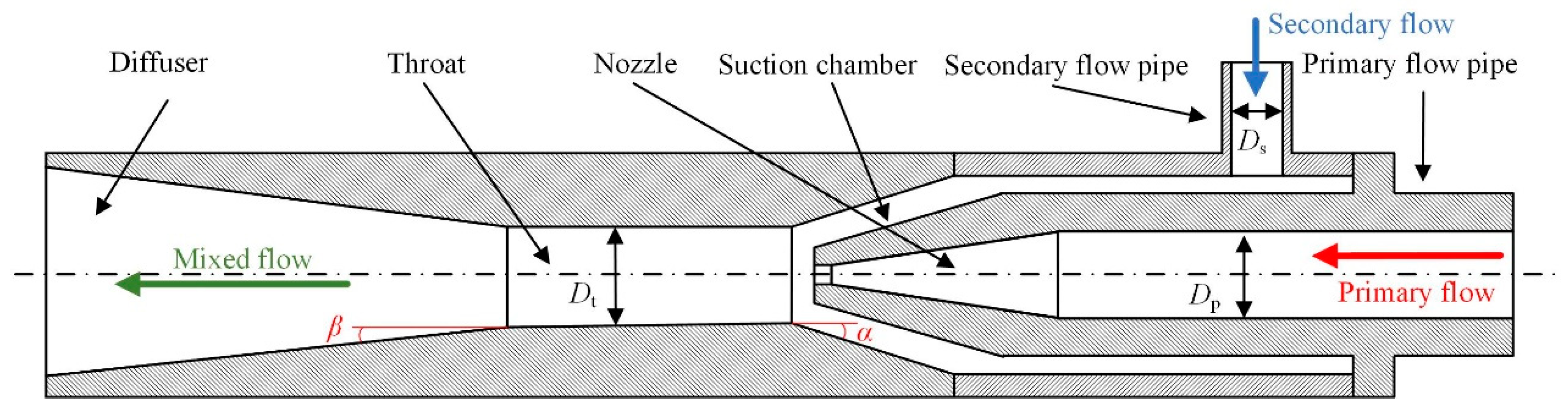
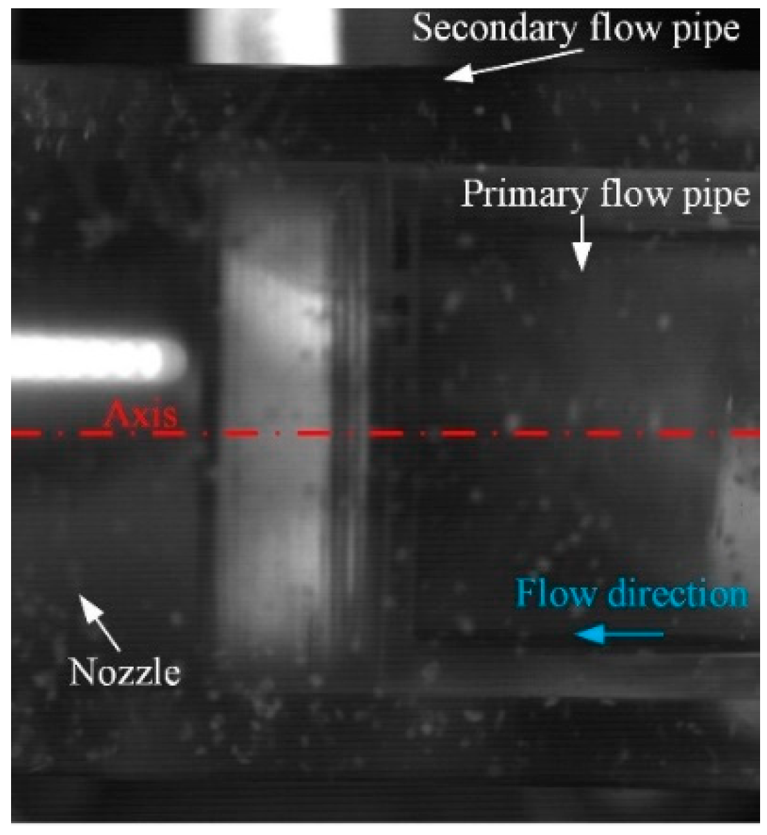
2.1. Jet Pump

The jet pump primarily consists of components such as a primary flow pipe, a secondary flow pipe, a nozzle, a suction chamber, a throat, and a diffuser, as illustrated in Figure 1. The operational principle of a jet pump is as follows: high-velocity working fluid is ejected from the nozzle. In the suction chamber (or convergent section), the working fluid entrains the suction fluid. Momentum and energy exchange occurs between the two streams within the suction chamber and throat, culminating in the high-speed mixed fluid being pressurized as it passes through the diffuser and subsequently exits the jet pump.
The fundamental performance parameters that describe a jet pump include the flow ratio q and the area ratio m, which are calculated as follows:
q = Q s Q p
Here, Qp and Qs are the mass flow of primary flow and secondary flow, respectively.
m = S t S n
Here, St and Sn are the cross-section areas of the jet pump nozzle outlet and throat, respectively.
In order to observe the movement of sand particles, a jet pump is made of plexiglass, and its main structural parameters are shown in Table 1.
The curvature of the outer wall can introduce biases in image acquisition. Therefore, the outer surfaces of the jet pump’s convergent duct, throat, and diffuser were planarized to enable the high-speed camera (Revealer X113M, HF Agile Device Co., Ltd., Hefei, China) to more accurately record the motion of the sand particles within the jet pump. Additionally, a separate convergent section and throat with a curved outer wall were fabricated for wear studies on the jet pump. To facilitate the description of the experimental setup details, a Cartesian coordinate system was established with the origin o located at the center of the throat inlet section (as shown in Figure 2). The positive direction of the x-axis aligns with the axis of the throat and the direction of the working fluid flow. The positive direction of the y-axis corresponds to the direction of the suction fluid flow within the suction conduit. The z-axis points in the direction opposite to gravity. The plane defined by xoz separates the region where y > 0 is the impact surface, and the region where y < 0 is the opposite surface. As depicted in Figure 2, four grooved slots, labeled s1, s2, s3, and s4, are evenly and circumferentially distributed at the axial position x = −17.7 mm within the suction chamber. Slots s1 and s2 are located on the impact surface, while slots s3 and s4 are on the opposite surface, with s1 and s4 positioned above s2 and s3, respectively. At the axial positions x = 37.8 mm and x = 81.8 mm within the throat, two grooved slots are circumferentially arranged and designated as t1, t2, t3, and t4, with t1 and t3 on the impact surface and t2 and t4 on the opposite surface. The grooves are filled with slot plates made of type 304 stainless steel (10 mm × 10 mm). During the experiment, measuring the mass loss of these slot plates reveals the macroscopic wear patterns caused by sand particles of different grain sizes on the jet pump’s wall. Replaceable slot plates facilitate repeated experiments on jet pump wall wear, helping to minimize experimental errors. Moreover, the small size of the slot plates is advantageous for observing the microstructure of wall wear.

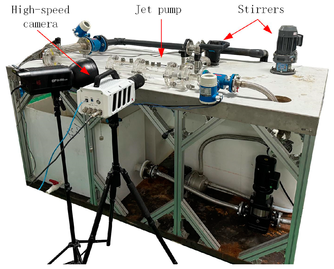
2.2. Experiment Materials and Device

White quartz sand was utilized in this experiment, with particle sizes of 0.65 mm, 0.85 mm, and 1.40 mm. The jet pump wear test rig designed for this study is illustrated in Figure 3. It primarily consists of a drive pump, a transparent jet pump, a piping circulation system, a flow and pressure data acquisition system, a sand particle agitator, a recirculating water tank, and valves. During the test, the flow within the jet pump can be controlled via the valves. The transparent jet pump is placed horizontally, ensuring that the heights of the inlet, suction inlet, and outlet are kept consistent.
The flow and pressure data acquisition system comprises a flowmeter, a pressure transmitter, and a data acquisition card. During the experiment, flow and pressure data signals need to be collected at the jet pump’s inlet, suction inlet, and outlet. The data acquisition system uses a data acquisition card to collect data from the flowmeter and pressure transmitter. For the experimental measurements, an FS01A flowmeter (with an accuracy class of 0.5) is employed to measure fluid flow, and a PCM300 pressure transmitter (with an accuracy class of 0.5) is used to measure pressure. A National Instruments (NI) USB-6009 data acquisition card is utilized to acquire flow and pressure signals. Within the sand-containing water tank, the mass concentration of each sand particle size is maintained at 50 kg/m³. To keep the sand particles suspended in the water, two agitators are installed in the sand-containing water tank. White irregular polygonal quartz sand is used in this experiment, and its physical properties are shown in Table 2.

2.3. Experiment Methods

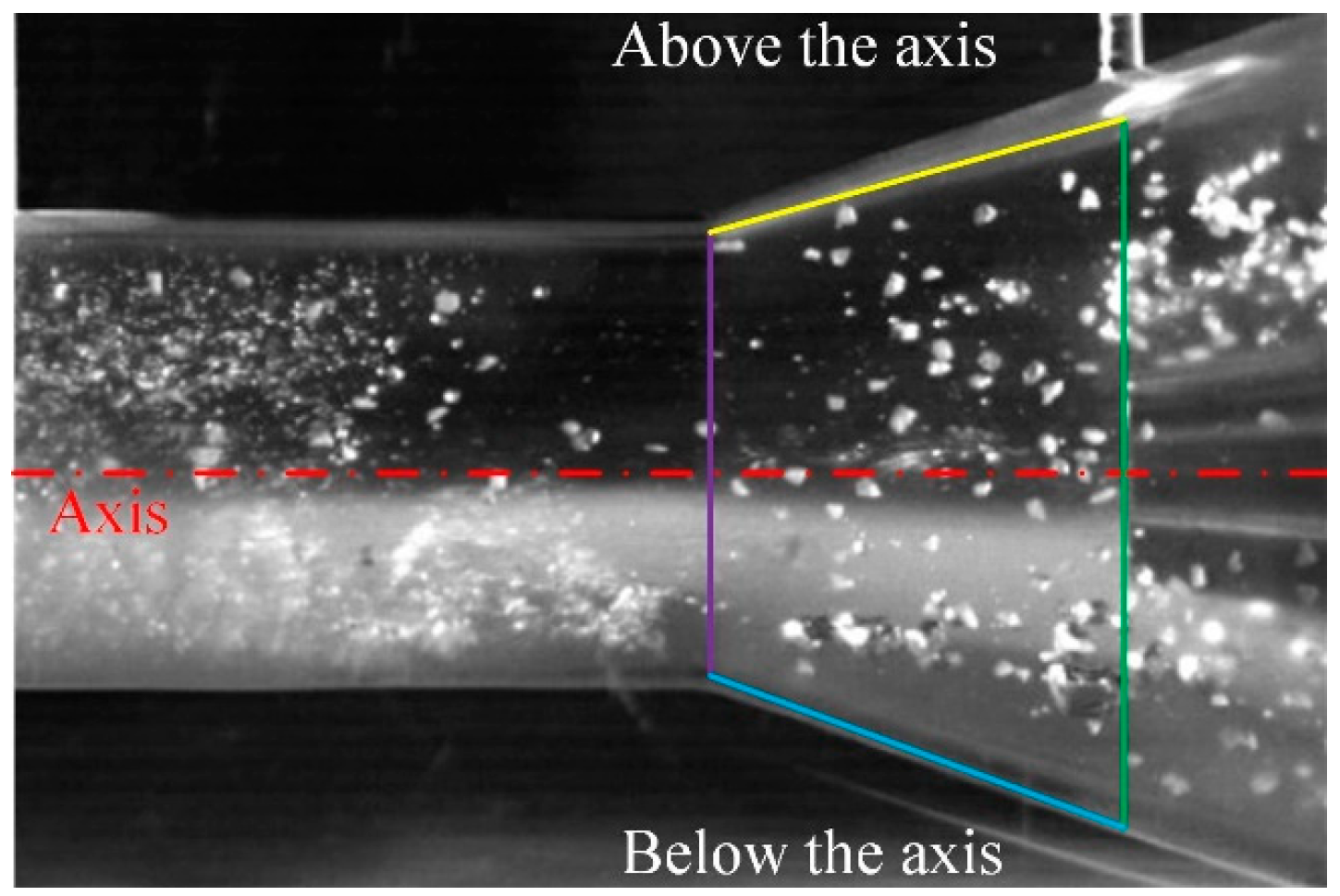
2.3.1. Visualization Experiment of Sand Movement in the Jet Pump

The experiment implied separately introducing sand particles of diameters 0.65 mm, 0.85 mm, and 1.40 mm into the sand-containing water tank and initiating the agitators. Once the sand particles in the tank were in suspension, the experiment commenced. By adjusting the valve opening, control over the flow state within the pump was achieved. The slurry mixture entered the jet pump through the suction fluid conduit. This study focused on the motion of sand particles of different sizes under various flow ratios q, as shown in Table 3.
In each operational condition, the high-speed camera was employed to record the movement of sand particles inside the pump, with the imaging area encompassing the convergent section and the throat. The captured images were grayscale, acquired at a frame rate of 5000 frames per second (FPS), with a single acquisition duration of 3 s. To more clearly observe the movement of sand particles within the jet pump, grayscale images of the convergent section and throat under pure water conditions were used as background images. The pixel values of the images under the sand particle conditions were subtracted from the pixel values of the background images at corresponding positions, yielding background-subtracted images (where the pixel values in areas without sand particles were set to 0, appearing black).

2.3.2. Wall Wear Experiment of the Jet Pump

The experiment first involved weighing and recording (averaging ten weighings) the mass of the slot plates (10 mm × 10 mm) made of type 304 stainless steel using an FA1004E analytical balance (Changzhou Lucky Electronic Equipment Co. Ltd., Changzhou, China, accuracy of 0.1 mg), and observing the surface microstructure of the slot plates with an SU8010 FE-SEM cold-field emission scanning electron microscope (Hitachi, Ltd., Tokyo, Japan). For this experiment, the convergent section and throat, which are used to study particle-induced wear on the wall, need to be mounted on the test bench with the slot plates inserted into the grooved slots. Sand particles of diameters 0.65 mm, 0.85 mm, and 1.40 mm were separately added to the sand-containing water tank, followed by starting the agitators. Once the sand particles in the tank were in suspension, the experiment began. The flow state within the pump was controlled by adjusting the valve aperture, with the slurry mixture entering the jet pump through the suction fluid conduit. The flow ratio q was set to 0.8. The wall wear experiment lasted for a total of 120 h, during which the dried slot plates were weighed and recorded (averaging ten weighings) every 12 h using the analytical balance. After the 120 h wear experiment, the surface microstructure of the slot plates was observed with a scanning electron microscope.

3. Results and Discussion

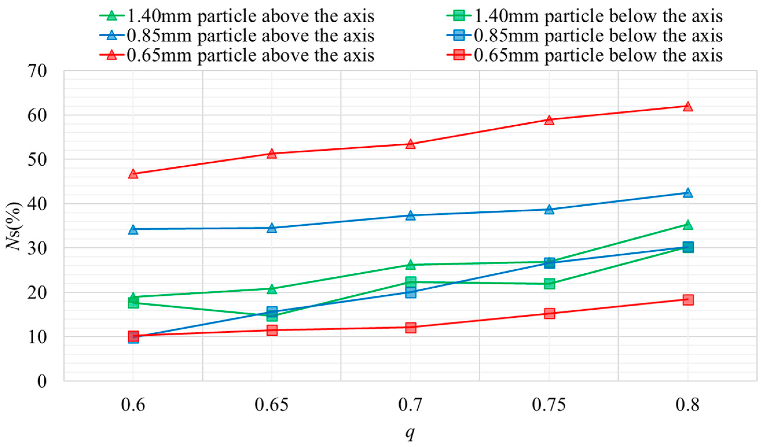
3.1. Sand Distribution and Movement Characteristics

During the experiment, the jet pump was laid out horizontally. Due to the structural constraints of the jet pump, the suction fluid inevitably comes into contact with the working fluid conduit. This results in the water–sand slurry being obstructed by the working fluid conduit before entering the convergent section, where the slurry must flow around the conduit from both above and below, as shown in Figure 2. Although the water–sand slurry is uniformly mixed by the agitator before entering the jet pump, the distribution of sand particles within the mixed fluid changes under the obstruction of the working fluid conduit. This alteration means that the sand particles are no longer uniformly distributed upon entry into the convergent duct, subsequently affecting the motion and distribution of sand particles within the jet pump significantly. To obtain the distribution state of sand particles prior to being influenced by the working fluid jet, this study delineates the flow region within the convergent section using the xoy plane as a boundary, dividing it into the region above the axis (the area enclosed by the green line, yellow line, purple line, and axis) and the region below the axis (the area enclosed by the green line, yellow line, blue line, and axis), as illustrated in Figure 4. For ease of describing the distribution of sand particles within the convergent section, the sand particle ratio Ns is defined, which is the proportion of sand particles in each region of the convergent section. This is calculated as the ratio of the number of pixels representing sand particles in that region to the total number of pixels in the region. The calculation method is as follows:
N s = S 2 S 1 × 100 %
Here, S1 is the total number of pixels in the area divided by the contraction chamber; S2 represents the number of pixels occupied by sand particles in the area divided by the contraction chamber.
Figure 5 shows the distribution of sand particles of different grain sizes within the convergent section under various operating conditions. From the figure, it can be observed that, for sand particles of all grain sizes, their proportions within the convergent section exhibit a positive correlation with q, indicating that the sand-carrying capacity of the jet pump increases with an increase in q. The reason for this result lies in the fact that operating conditions with higher q values have a stronger entrainment ability for the water–sand slurry. With the sand concentration remaining constant, the number of sand particles entering the jet pump increases, consequently increasing the quantity of sand particles passing through each region; hence, the proportions of sand particles in each region show an upward trend. In the convergent section, the grain size of the sand particles has a significant impact on their distribution. It can be seen from the figure that, for 0.65 mm grain size sand particles, the proportion above the axis is much higher than that below the axis, and with the increase in q, the difference grows from 37% (q = 0.6) to 44% (q = 0.8). For larger grain size sand particles (such as 1.40 mm grain size sand particles), the proportion of sand particles above the axis is very close to that below the axis. This phenomenon is primarily attributed to two reasons: firstly, after the working fluid is injected into the convergent section through the nozzle, its flow exhibits a jet-like pattern. The high-velocity water expands radially, and smaller grain size sand particles have a larger specific surface area, thus experiencing a stronger effect from the water flow within the convergent section, resulting in a more dispersed distribution; secondly, the experiment uses the same mass of sand particles to ensure that the water–sand slurry has the same mass concentration. Therefore, under the premise of the same mass concentration, a larger number of smaller grain size sand particles are present.
Furthermore, the distribution of sand particles of different grain sizes within the convergent section of the jet pump, as shown in Figure 5, all exhibit a higher proportion of sand particles above the axis compared to those below the axis. This experimental result contradicts intuition, which would suggest that, under the influence of gravity, the proportion of sand particles (which are denser than water) below the axis should be greater than that above. To explore the cause of this outcome, our study utilized high-speed videography to capture the distribution of sand particles upstream of the nozzle, specifically at the junction where the working fluid conduit meets the suction fluid conduit, as depicted in Figure 6. Clearly visible from the figure, there are more sand particles below the axis than above, which aligns with the intuitive understanding of how sand particles distribute under gravitational effects. Thus, based on the sand particle motion captured by the high-speed camera, the reason for the change in sand particle distribution becomes apparent. The water–sand slurry flows horizontally along the suction fluid conduit, with sand particles under the influence of gravity exhibiting a distribution wherein fewer particles are found above the axis and more below, with the proportion of particles settling due to gravity increasing as the grain size of the sand particles increases. Upon reaching the junction of the working fluid conduit and the suction fluid conduit, the water–sand slurry splits into two streams circumventing the working fluid conduit due to the obstruction it presents, as shown in Figure 2. At the point where the conduits meet, the drastic change in flow direction and the reduction in cross-sectional flow area result in the force exerted by the water on the sand particles being significantly greater than the gravitational force acting on them. The circumferential motion of the water–sand slurry leads to sand particles originally below the axis moving upwards and those above the axis moving downwards. This results in the experimental finding that the proportion of sand particles above the axis at the nozzle exit is greater than that below the axis. This phenomenon is primarily due to the fluid dynamics at the nozzle exit overriding the gravitational effects that would otherwise dictate the distribution of sand particles.

3.2. Macroscopic Wear Characteristics of Sand on Wall Surface

To investigate the wear characteristics of different grain size sand particles on the jet pump’s wall, the experiment studied the mass loss of the slot plates on the pump wall during 120 h of continuous operation. The mass of the slot plates was weighed every 12 h, and the wear amount M was calculated as follows:
M = M 0 M t
Here, M0 is the initial mass of the slot plate before the start of the experiment, and Mt is the mass of the slot plate at any given time t during the experiment.
Based on the experimental results, we obtained the wear on the slot plates in the convergent section (Figure 7) and the wear on the slot plates in the throat (Figure 8). Analyzing the experimental results from the perspective of wear time reveals that, for sand particles of different grain sizes and different wear locations, the mass loss of the slot plates shows a positive correlation with wear time, meaning that the longer the wear time, the greater the mass loss of the slot plates. This is fairly evident, as particle wear is a cumulative process over time, and as time progresses, the wear volume gradually increases. From the perspective of grain size, under the premise of the same mass concentration, sand particles with smaller grain sizes cause more significant wear and greater mass loss to the jet pump. The reason for this phenomenon lies in the fact that smaller grain size sand particles have a larger specific surface area, making them more susceptible to impact, exhibiting motion characteristics closer to that of the water flow within the pump. They have a smaller velocity differential relative to the water flow, and when carried by the radial flow of water, they strike the wall at a higher velocity. For larger grain size sand particles, the effect of the water flow within the pump on their motion is less pronounced. Under the influence of inertia, their ability to change speed is weaker, leading to a greater velocity differential relative to the water flow, and thus they impact the wall at a lower radial velocity. According to the impulse–momentum theorem, the force exerted on the wall by the sand particles is directly related to their mass and velocity. Consequently, under the same mass concentration, smaller grain size sand particles exert a greater impact force on the pump wall compared to larger grain size sand particles. Furthermore, the number of collisions between sand particles and the jet pump wall increases with the number of sand particles, and the increased collision frequency also places the wall material in a state of fatigue, resulting in a greater wear.
After calculations, the mass loss per unit area of the slot plates in the convergent section after 120 h ranged from 0.012 mg/mm2 to 0.027 mg/mm2. As depicted by the variations in wear amounts of slot plates at different positions within the convergent section, as shown in Figure 7, for sand particles of the same grain size, slot plates s1 and s2 on the impact surface exhibited slightly higher wear amounts compared to slot plates s3 and s4 on the opposite surface. This outcome is closely related to the motion of sand particles within the jet pump. As discussed earlier, upon entering the convergent section, sand particles are obstructed by the working fluid conduit, forcing them to flow circumferentially around the conduit both above and below it. The two streams of water–sand mixture then move circumferentially to collide, mix, and accumulate at the impact surface. This results in a noticeably higher number of sand particles at the impact surface than at the opposite surface. Consequently, after being accelerated by the working fluid, a greater number of sand particles collide with the wall on the impact side, leading to a slightly higher wear amount on the impact surface than on the opposite surface. Moreover, the previously discussed distribution of sand particles within the convergent section explains the reason for the effect of sand particle grain size on the wear characteristics of the slot plates in the convergent section. Smaller grain size sand particles (e.g., 0.65 mm) are notably more prevalent above the axis than below it. Thus, the results of the slot plate mass loss demonstrate that slot plates s1 and s4, which are located above the axis, have greater mass losses than their counterparts s2 and s3 on the same side.
The mass loss of the slot plates at the throat is significantly higher than that in the convergent section, due to the fact that sand particles gradually accelerate under the influence of the working fluid. As the sand particles pass through both the convergent section and the throat, the sand particles in the throat attain higher velocities, resulting in greater impact forces against the walls. Unlike the relatively uniform wear across different sections within the convergent section, the wear on the slot plates in the throat displays distinct characteristics. Specifically, the mass loss of slot plates t3 and t4 at the middle of the throat is considerably higher than that of slot plates t1 and t2 at the front sides of the throat. Notably, after 120 h of wear testing with 0.65 mm grain size sand particles, the mass loss of slot plate t3 approaches 10 mg, significantly exceeding others. Figure 9 depicts the movement of sand particles within the convergent section and the throat, as recorded by the high-speed camera. Analysis of the images reveals that sand particles undergo rotational motion in the middle of the throat, with a distinct recirculation zone present. The flow characteristics of water jets in confined spaces are the primary cause of the recirculation of sand particles in the middle of the throat. Following ejection from the nozzle, the working fluid experiences not only axial motion but also radial expansion. However, constrained by the throat walls, the radial flow gradually transforms into a backflow that moves counter to the main flow direction, subsequently redirecting toward the axis to mix with the working fluid and form a new central jet. Under the influence of this backflow, sand particles engage in repetitive rotations, repeatedly colliding with the walls in the middle of the throat, leading to severe wear. Hence, under the impact of sand particle collisions, the mass loss in the middle of the throat is markedly greater than in other parts of the jet pump.

3.3. Microscopic Wear Characteristics of Sand on Wall Surface

In addition to studying the macroscopic mass loss due to sand particle-induced wear on the jet pump wall, SEM (scanning electron microscopy) technology was employed to observe the wear on the pump wall at a microscopic level. A 304 stainless steel slot plate that had not undergone any experimental treatment served as the control group, with its surface microstructure depicted in Figure 10. From the figure, it can be observed that the surface of the slot plate is smooth and uniform, with only minor traces of machining marks present. In the experiments, these machining marks are perpendicular to the axial flow direction of the water within the pump, and therefore do not interfere with the investigation of the microscopic wear on the slot plate surfaces.
Figure 11 illustrates the surface microstructures of slot plates at different locations within the jet pump after 120 h of wear testing with sand particles of varying grain sizes. From the micrographs, it is evident that the types of wear on the pump wall can be categorized into pits and scratches. Observing the surface microstructures of the slot plates from the perspective of sand particle grain size reveals that smaller grain size sand particles, as seen in Figure 11(1a,1f), leave multiple layers of fine cutting marks on the slot plate surfaces, whereas larger grain size sand particles, as seen in Figure 11(3a,3b), produce deeper scratches. As previously discussed, larger grain size sand particles possess greater momentum, which enables them to create deeper scratches. Under the same mass concentration, smaller grain size sand particles occur in greater numbers, leading to a richer and denser layer of cutting marks on the slot plate surfaces due to the higher frequency of impacts from lighter particles.
The surface microstructures of the slot plates in the convergent section predominantly display a flake-like appearance, accompanied by a few small pits, and the scratch directions are not entirely aligned with the axial flow direction within the pump, as seen in Figure 11(3c). This is because sand particles entering the convergent section still exhibit a significant circumferential motion characteristic, and the rolling process along the wall leaves non-mainstream direction scratches on the slot plate surfaces. As the grain size of the sand particles decreases, the density of micro-pores on the convergent section slot plate surfaces increases, forming widespread micro-pore clusters, with some erosion residues appearing on the slot plate surfaces, as seen in Figure 11(1d,3d). These erosion residues are generated when sand particles impact the slot plate surfaces, causing the detachment of surface material from the slot plates. However, due to the insufficient energy from the particle impacts, the surface material is not completely removed, leaving some material still attached to the slot plates in the form of erosion residues.
The micro-wear condition of the slot plates in the throat is not entirely similar to that in the convergent section. Their surfaces feature more scratches aligned with the axial flow direction and more pronounced cutting characteristics, as seen in Figure 11(3c,3g). The kinematic characteristics of sand particles in the throat play a critical role in generating this surface microfeature. Sand particles gain acceleration in the throat, displaying a motion characteristic dominated by axial movement, supplemented by radial motion, with weak circumferential motion. This results in the micro-wear structure of the throat slot plates predominantly exhibiting axial scratches. Compared to slot plates at other locations, the slot plates in the central region of the throat show a higher number of pits. This is associated with the presence of a recirculation zone in the middle of the throat, where the backflow causes a significant deflection in the direction of some sand particles, leading them to impact the pump wall at a larger angle and create pits.

4. Conclusions and Outlook

The wall wear characteristics of a jet pump conveying water–sand slurries containing sand particles of different grain sizes were investigated through experimental methods. High-speed videography was employed to record and describe the movement of sand particles within the pump, while the weight loss method measured the mass loss of wall surfaces at various locations inside the pump under different wear durations, summarizing the patterns observed. Scanning electron microscopy (SEM) was applied to observe the microstructural features of wall wear and analyze the causes behind these features. The following conclusions are drawn:
(1)
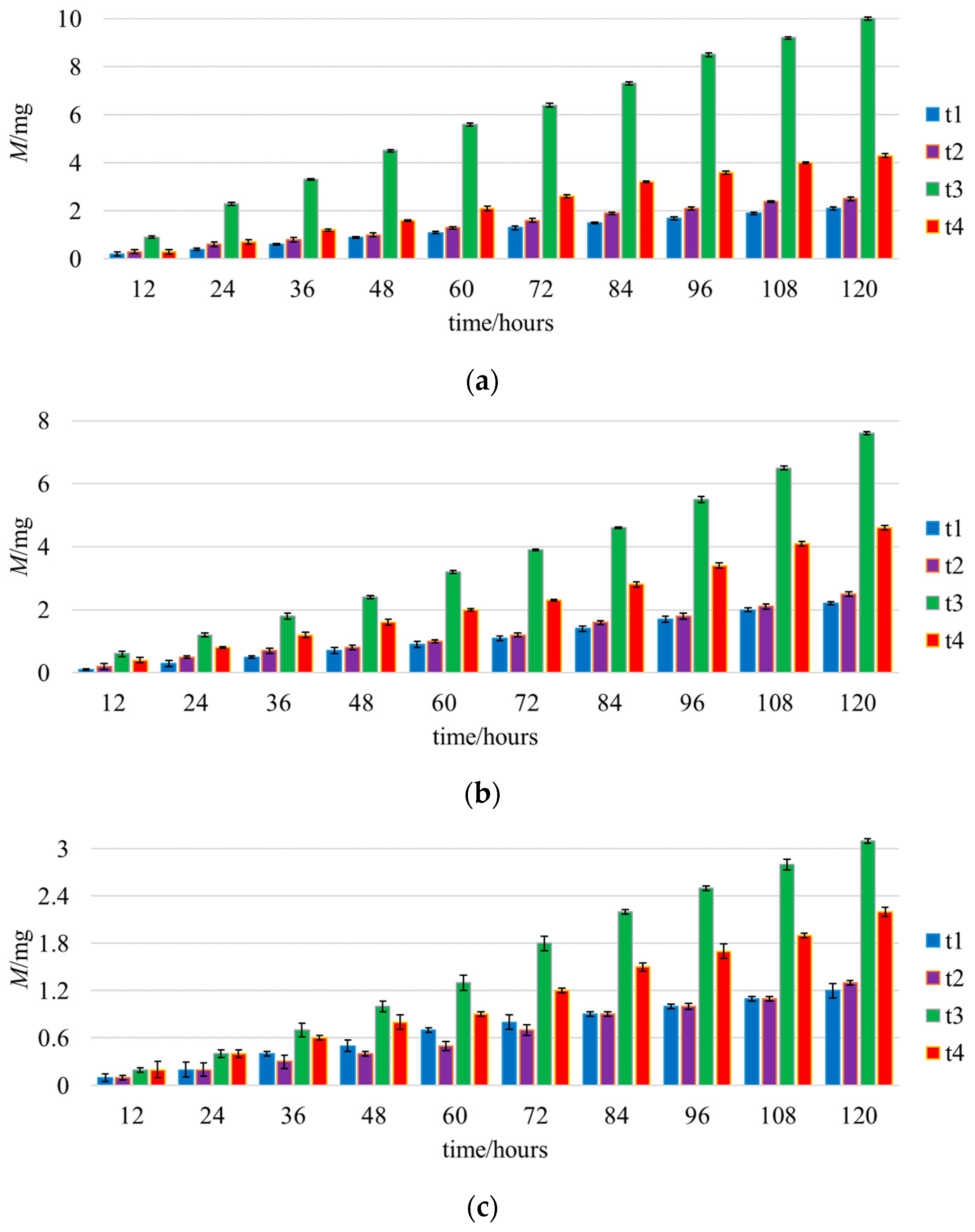
Within the convergent section, the proportion of sand particles increases with the rise in the flow ratio. When sand particles enter the jet pump, they encounter resistance from the working fluid conduit, leading to circumferential flow around the conduit. This causes a higher proportion of sand particles above the axis than below, with the difference in distribution negatively correlated with particle grain size.
(2)
From a macroscopic wear perspective, under the same mass concentration conditions, smaller grain size sand particles lead to a greater mass loss of the pump wall material. The mass loss of pump wall material is positively correlated with the duration of the wear experiment. The circumferential flow around the conduit when sand particles enter the pump results in a distribution wherein more particles are on the impact side and fewer on the opposite side, contributing to a greater mass loss on the impact side compared to the opposite side.
(3)
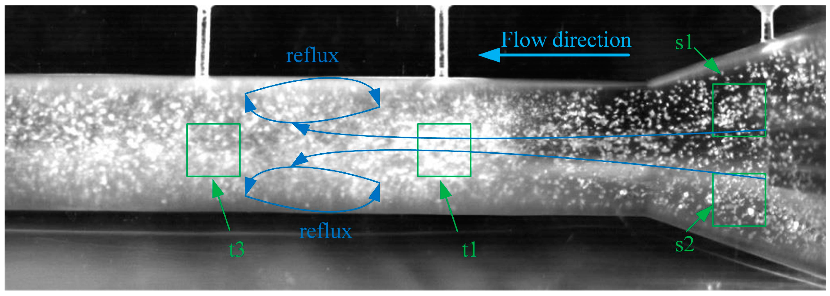
The mass loss of slot plates at various locations within the convergent section is relatively consistent, whereas the mass loss of slot plates at different positions in the throat shows significant variation. The diffusion of working fluid in the confined space triggers a pronounced recirculation in the middle of the jet pump throat, causing repeated particle impacts on the wall, manifesting as a significantly greater mass loss of slot plates in the middle of the throat compared to other locations.
(4)
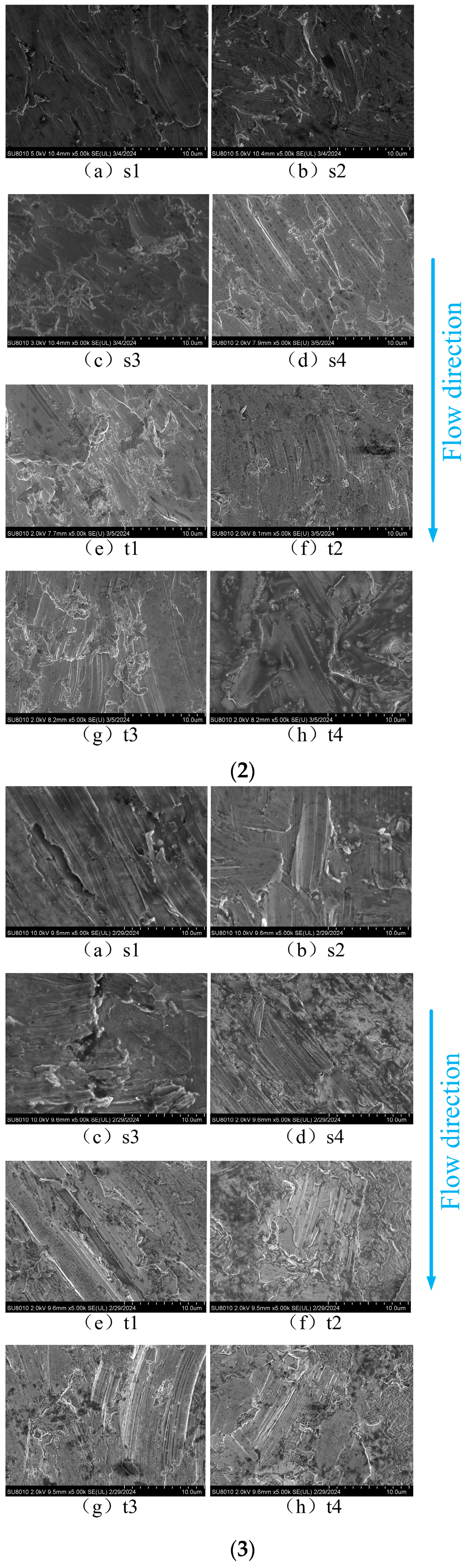
From a microscopic perspective, the wear types on the pump wall material are primarily pits and scratches. Sand particles of different grain sizes exhibit distinct wear characteristics on the pump wall material. Smaller grain size sand particles leave multiple layers of fine cutting marks on the slot plate surfaces, while larger grain size sand particles create deeper scratches. Influenced by the low-speed circumferential water flow in the convergent section, the wear structures left on the slot plate surfaces mostly appear flake-like, with fewer micro-pits, and the scratch directions are not entirely aligned with the axial flow direction within the pump. In contrast, the rapid flow and pronounced recirculation characteristics in the throat result in a micro-wear structure dominated by axial scratches, with many pits appearing on the slot plate surfaces in the middle of the throat.
Severe localized wear on the jet pump wall can affect pump performance and even lead to failure. Therefore, reducing and evenly distributing wall wear contribute to the safety and stability of solid–liquid two-phase flow transportation. Based on the macroscopic and microscopic characteristics of sand particle distribution and wall material wear within the jet pump, it is evident that sand particles are significantly influenced by the working fluid conduit upon entry, leading to uneven distribution. This causes noticeable differences in wear conditions around the circumference of the pump. Future research could consider modifying the angle between the suction fluid conduit and the working fluid conduit to promote a more uniform distribution of sand particles upon entry into the jet pump, thereby preventing excessive localized wear. Additionally, the recirculation phenomenon in the throat is a significant cause of uneven wear on the pump wall. Future studies may explore pump structural parameters and flow control measures to suppress recirculation in the throat, thereby extending the service life of the jet ump in solid–liquid two-phase flow transportation.

Author Contributions

Conceptualization, M.X.; methodology, H.Q.; investigation, C.F.; resources, J.L.; data curation, Z.D.; writing—original draft preparation, C.F.; writing—review and editing, M.X. and H.Q.; visualization, C.F. All authors have read and agreed to the published version of the manuscript.

Funding

This research was funded by Zhejiang Provincial Natural Science Foundation of China under Grant NO. LGG22E090001, Key R&D Program of Zhejiang under Grant NO. 2022C02035, Ministry of Water Resources of the People’s Republic of China under Grant NO. SKS-2022053, Zhejiang Provincial Natural Science Foundation under Grant NO. LTGG24E060001 and the Basic Public Welfare Research Project of Zhejiang Province under Grant NO. LGG22F030024.

Institutional Review Board Statement

Not applicable.

Informed Consent Statement

Not applicable.

Data Availability Statement

No new data were created or analyzed in this study. Data sharing is not applicable to this article.

Acknowledgments

The authors are very grateful to the Institute of Fluid Equipment and Inspection Technology, China Jiliang University, for supporting this study.

Conflicts of Interest

Author Jian Liu was employed by the company Zhejiang Hangke Technology Incorporated Company. The remaining authors declare that the research was conducted in the absence of any commercial or financial relationships that could be construed as a potential conflict of interest.

References

  1. Pellegrini, M.; Preda, G.; Saccani, C. Application of an Innovative Jet Pump System for the Sediment Management in a Port Channel: Techno-Economic Assessment based on Experimental Measurements. J. Mar. Sci. Eng. 2020, 8, 686. [Google Scholar] [CrossRef]
  2. Long, X.; Zuo, D.; Cheng, H.; Ji, B. Large eddy simulation of the transient cavitating vortical flow in a jet pump with special emphasis on the unstable limited operation stage. J. Hydrodyn. 2019, 32, 345–360. [Google Scholar] [CrossRef]
  3. Chen, S.; Yang, D.; Zhang, Q.; Wang, J. An integrated sand cleanout system by employing jet pumps. J. Can. Pet. Technol. 2009, 48, 17–23. [Google Scholar] [CrossRef]
  4. Liu, W.; Lai, X.; Zhu, C.; Zhou, Q.; Yang, X. Effect of sand diameter on the performance of annular jet pumps. Journal of Physics: Conference Series. In Proceedings of the 17th Asian International Conference on Fluid Machinery (AICFM 17 2023), Zhenjiang, China, 20–23 October 2023. [Google Scholar]
  5. Long, X.; Xu, M.; Lyu, Q.; Zou, J. Impact of the internal flow in a jet fish pump on the fish. Ocean Eng. 2016, 126, 313–320. [Google Scholar] [CrossRef]
  6. Oka, Y.I.; Okamura, K.; Yoshida, T. Practical estimation of erosion damage caused by solid particle impact: Part 1: Effects of impact parameters on a predictive equation. Wear 2005, 259, 95–101. [Google Scholar] [CrossRef]
  7. Xu, K.; Wang, G.; Zhang, L.; Wang, L.; Yun, F.; Sun, W.; Wang, X.; Chen, X. Multi-objective optimization of jet pump based on RBF neural network model. J. Mar. Sci. Eng. 2021, 9, 236. [Google Scholar] [CrossRef]
  8. Reis, L.B.; dos Santos Gioria, R. Optimization of liquid jet ejector geometry and its impact on flow fields. Appl. Therm. Eng. 2021, 194, 117132. [Google Scholar] [CrossRef]
  9. Hill, P.G. Turbulent jets in ducted streams. J. Fluid Mech. 1965, 22, 161–186. [Google Scholar] [CrossRef]
  10. Zhdanov, V.; Kornev, N.; Hassel, E.; Chorny, A. Mixing of confined coaxial flows. Int. J. Heat Mass Transf. 2006, 49, 3942–3956. [Google Scholar] [CrossRef]
  11. Song, X.; Park, J.; Kim, S.; Park, Y. Performance comparison and erosion prediction of jet pumps by using a numerical method. Math. Comput. Modell. 2013, 57, 245–253. [Google Scholar] [CrossRef]
  12. Xu, M.; Yang, X.; Long, X.; Lyu, Q.; Ji, B. Numerical investigation of turbulent flow coherent structures in annular jet pumps using the LES method. Sci. China Technol. Sci. 2018, 61, 86–97. [Google Scholar] [CrossRef]
  13. Xu, K.; Wang, G.; Wang, L.; Yun, F.; Sun, W.; Wang, X.; Chen, X. Parameter analysis and optimization of annular jet pump based on kriging model. Appl. Sci. 2020, 10, 7860. [Google Scholar] [CrossRef]
  14. Gant, A.; Gee, M.; Plint, G. A new concept in liquid jet erosion: Commissioning and proving trials. Wear 2007, 263, 284–288. [Google Scholar] [CrossRef]
  15. Oka, Y.; Yoshida, T. Practical estimation of erosion damage caused by solid particle impact: Part 2: Mechanical properties of materials directly associated with erosion damage. Wear 2005, 259, 102–109. [Google Scholar] [CrossRef]
  16. Noon, A.A.; Kim, M.H. Erosion wear on centrifugal pump casing due to slurry flow. Wear 2016, 364, 103–111. [Google Scholar] [CrossRef]
  17. Zou, C.; Li, H.; Xiang, Q. Integrated method of optimizing jet pump anti-wear performance. J. Drain. Irrig. Mach. Engin 2020, 38, 109–114. [Google Scholar]
  18. Khalil, M.F.; Kassab, S.Z.; Naby, A.A.A.; Azouz, A. Performance characteristics of centrifugal pump conveying soft slurry. Am. J. Mech. Eng. 2013, 1, 103–112. [Google Scholar] [CrossRef]
  19. Tarodiya, R.; Gandhi, B.K. Experimental investigation of centrifugal slurry pump casing wear handling solid-liquid mixtures. Wear 2019, 434, 202972. [Google Scholar] [CrossRef]
Figure 1. Structure of a jet pump.
Jmse 12 01390 g001
Figure 2. Diagram of slot position.
Jmse 12 01390 g002
Figure 3. Jet pump wear test rig.
Jmse 12 01390 g003
Figure 4. Schematic diagram of sand movement area in suction chamber.
Jmse 12 01390 g004
Figure 5. Sand distribution in suction chamber.
Jmse 12 01390 g005
Figure 6. Sand distribution at the connection between primary and secondary flow pipes.
Jmse 12 01390 g006
Figure 7. Mass loss of slot plates in the suction chamber under the influence of sand particles of different grain sizes: (a) 0.65 mm, (b) 0.85 mm, (c) 1.40 mm.
Jmse 12 01390 g007
Figure 8. Mass loss of slot plates in the throat under the influence of sand particles of different grain sizes: (a) 0.65 mm, (b) 0.85 mm, (c) 1.40 mm.
Jmse 12 01390 g008
Figure 9. Motion of sand particles in the suction chamber and throat.
Jmse 12 01390 g009
Figure 10. Surface microstructure of untested 304 stainless steel (control group).
Jmse 12 01390 g010
Figure 11. Micromorphology of grooves subjected to sand wear of different particle sizes: (1) 0.65 mm, (2) 0.85 mm, (3) 1.40 mm.
Jmse 12 01390 g011aJmse 12 01390 g011b
Table 1. Main structural parameters of the jet pump.
StructureDiameter of Primary Flow Pipe DpDiameter of Secondary Flow Pipe DsDiameter of Throat DtArea Ratio mHalf Angle of Contraction αHalf Angle of Diffusion β
Size25 mm25 mm25 mm6.2520°
Table 2. Sand physical properties.
Physical CharacteristicsParticle DensityPercentage of BreakageAttrition RateMohs Hardness
Data2.66 g/cm30.51%0.35%7.5
Table 3. Experimental condition.
CaseqQp (m3/h)Qs (m3/h)
10.64.382.63
20.654.382.85
30.74.373.06
40.754.383.29
50.84.363.49
Disclaimer/Publisher’s Note: The statements, opinions and data contained in all publications are solely those of the individual author(s) and contributor(s) and not of MDPI and/or the editor(s). MDPI and/or the editor(s) disclaim responsibility for any injury to people or property resulting from any ideas, methods, instructions or products referred to in the content.

