Article

Comparative Study on the Performances of a Hinged Flap-Type Wave Energy Converter Considering Both Fixed and Floating Bases

1
Key Laboratory of High Performance Ship Technology (Wuhan University of Technology), Ministry of Education, Wuhan 430063, China
2
School of Naval Architecture, Ocean and Energy Power Engineering, Wuhan University of Technology, Wuhan 430063, China
3
Centre for Marine Technology and Ocean Engineering (CENTEC), Instituto Superior Técnico, Universidade de Lisboa, 1649-004 Lisbon, Portugal
4
China Ship Scientific Research Center, Wuxi 210084, China
5
China Southern Power Grid Technology Co., Ltd., Guangzhou 510080, China
6
China Datang Corporation Ltd., Guangdong Branch, Guangzhou 510000, China
7
Guangdong Datang International Chaozhou Power Generation Co., Ltd., Chaozhou 515700, China
*
Author to whom correspondence should be addressed.
J. Mar. Sci. Eng. 2024, 12(8), 1416; https://doi.org/10.3390/jmse12081416
Submission received: 27 July 2024 / Revised: 14 August 2024 / Accepted: 15 August 2024 / Published: 17 August 2024
(This article belongs to the Special Issue Offshore Renewable Energy, Second Edition)

Abstract

:
The dynamical modeling and power optimization of floating wind–wave platforms, especially in regard to configurations based on constrained floating multi-body systems, lack in-depth systematic investigation. In this study, a floating wind-flap platform consisting of a flap-type wave energy converter and a floating offshore wind turbine is solved in the frequency domain considering the mechanical and hydrodynamic couplings of floating multi-body geometries and a model that suits the constraints of the hinge connection, which can accurately calculate the frequency domain dynamic response of the flap-type WEC. The results are compared with bottom-fixed flap-type wave energy converters in the absence of coupling with a floating wind platform. Moreover, combined with traditional optimization methods of power take-off systems for wave energy conversion, an optimization method is developed to suit the requirements of floating wind-flap platform configurations. The results are drawn for a specific operation site in the South China Sea, whereas a sensitivity analysis of the parameters is performed. It is found that the floating wind-flap platform has better wave energy absorption performance in the low-frequency range than the bottom-fixed flap-type wave energy converter; the average power generation in the low-frequency range can increase by up to 150 kW, mainly due to constructive hydrodynamic interactions, though it significantly fluctuates from the sea waves’ frequency range to the high-frequency range. Based on spectral analysis, operational results are drawn for irregular sea states, and the expected power for both types of flap-type WECs is around 30 kW, which points to a similar wave energy absorption performance when comparing the bottom-fixed flap with the flap within the hybrid configuration.

1. Introduction

In the last decades, marine renewable energies have attracted the interest of the scientific community due to the vast amounts of tidal, wind and wave energies that are present in offshore regions [1]. Whereas solutions based on bottom-fixed wind turbines nowadays operate worldwide, in order to become economically feasible to exploit the many other sources of marine renewable energy, research and improvement are still required due to missing gaps in technology development. At present, offshore wind energy is developing fast, and it is one of the most promising renewable energy sources; thus exploiting offshore wind power has become an important development direction of the wind energy industry [2]. Moreover, in 2020, China put forward the carbon peaking and carbon neutrality goals, which led to new development requirements for the renewable energy market in China. In consequence, by 2023, China had become the country with the largest offshore wind power market for three consecutive years [3]. Offshore renewable energy, mostly represented by offshore wind and offshore wave energy, is the key to the realization of the carbon peaking and carbon neutrality goals.
Regarding solutions based on floating platforms, Hywind Demo 2.3 MW was the world’s first full-scale floating offshore wind turbine (FOWT) project [4]. It was launched in 2009 in the Norwegian Sea. Later, in 2017, the world’s first floating wind farm was built in the UK, namely, the Hywind Scotland wind farm, with 30 MW of wind power [5]. In 2021, China’s first full-scale floating wind turbine was built in Yangjiang, Guangdong, namely, the Three Gorges Pilot [6]. The “Haiyou Guanlan” and “Mingyang Tiancheng” FOWT project was completed in China recently [7,8]. However, there are still some limitations to the development of FOWTs: the missing gaps in FOWT development are the high structural and installation costs and the poor structural safety and reliability [9]. Those factors restrict the large-scale commercial development of floating wind power [10].
Combining FOWTs with wave power generation devices can improve the total power generation, and at the same time, a reasonable arrangement of wave devices can effectively restrain the motion responses of the floating foundation, thus improving the structural safety [11]. Bearing that in mind, many scholars have put forward conceptual designs that integrate wave energy conversion devices into FOWTs. The spar–torus combination (STC) is an early conceptual design combining a spar FOWT and a torus wave energy converter (WEC) around the spar. The motion response and power generation of the STC hybrid platform was analyzed by Muliawan et al. [12]. O’Sullivan et al. [13] designed the delta oscillating water column (OWC) array, combining wind and wave power devices in a single platform based on a triangular semi-submersible geometry, also analyzing the reliability of the platform. Zhang et al. [14] also combined the OWC with the FOWT and analyzed the power generation by equating the OWC to the point absorber. Chen et al. [15] designed a wind–wave combined platform based on the WindFloat semi-submersible and WECs near the center of the three-column platform, making full use of the “wave-gathering” effect that may exist in the wave field and thus improving the motion performance of the WEC. The in-depth investigation was further advanced by comparing WEC arrays in different configurations [16]. Ren et al. [17] put forward a TLP wind and wave combined platform, the TWWC, that stands for TLP-WT-WEC-combination. In the latter design, the wave power generation device is nested in the wind turbine tower, improving the power generation, though at rated power, the wind energy is still the main source of power. Shi et al. [18] presented a new wind–wave combined power generation platform and conducted the optimization of the WEC size and power take-off (PTO) coefficients.
The abovementioned research has put forward many concepts and conducted a lot of investigation on wind–wave combined power generation platforms. However, most of the abovementioned wind–wave combined power generation platforms employ point-absorber WECs that use only the heave motion to generate power. There is also some research on flap-type WECs [19] and floating offshore wind turbine platforms. Flap-type WECs may benefit from the surge motion and have been studied in-depth, especially in bottom-fixed solutions [20], whereas novel flap designs with nontrivial geometries may significantly enhance wave power performance [21]. That said, Michailides et al. [22] designed a structure combining a flap-type WEC with a semi-submersible floating platform—named SFC, which stands for semi-submersible-flap combination, and studied its power generation performance. Si et al. [23] designed a kind of hinged point-absorber WEC with the foundation of a semi-submersible platform, similar to a flap-type, and studied the system control method of the platform. Celesti et al. [24] conducted a numerical investigation on the motion response of a three-column semi-submersible platform with a flap-type WEC, though the constrained motion is oversimplified, and only 2 degrees of freedom are accounted for in the simulations.
The research on the optimization of flap-type WECs in hybrid platform configurations is limited to the PTO coefficient and geometric size optimization. There is no research on the difference of the power generation mechanism between WECs only and WECs in a wind–wave combined power generation platform.
The equation of motion of a multi-degrees of freedom coupled platform based on potential flow theory is normally constructed by accounting for the hinged constraint matrix. This model has been considered by many scholars to investigate the motions of ships and aquaculture cages. Ma et al. [25] built a coupled dynamic model of two cages and analyzed the dynamic characteristics of the floating multi-body aquaculture platform. Wang et al. [26] built a dynamic model of a three-body hinged barge and arranged a PTO device in the middle of the barge, thus studying the ship motion characteristics and potential power generation from relative motion. Ren et al. [27] established a modular multi-purpose floating structure system by constructing a rigid–flexible coupling link matrix and investigated the influence of different connector types on the system motion response and constraint forces. Chen et al. [28] developed a coupled hydrodynamic–structural model for three hinged bodies, considering the effects of the flexibility of the hinged connection.
That said, the hinged constraint model is a mature method to construct equations of the motion of floating multi-body systems, but there is not enough work to apply this method on flap-type WECs with a FOWT. Also, it is important to provide a comparison between the motion characteristics and power generation of a single WEC with the WECs in a hybrid configuration; that shall be in focus in this paper. Moreover, in this paper, the motion response and power generation performance of the two models, namely, the bottom-fixed flap-type WEC and the flap-type WEC in a floating wind-flap platform (FWFP from hereafter) are discussed. Based on frequency domain results, the equation of motion suitable for the FWFP is established by using the hinged constraint matrix method, and the results are validated time domain results obtained from numerical simulations in Ansys AQWA 2023 R1®. This software has been used for several hydrodynamic analyses and various types of floating multi-body geometries [29,30]. The differences between the bottom-fixed flap-type WEC and the flap-type WEC in the FWFP in terms of natural frequency, optimal damping ratio and expected wave absorbed power in South China Sea conditions are comprehensively compared, and the applicability of the optimization method is discussed.
The rest of this paper is arranged as follows: Section 2 introduces the method for the construction of the equation of motion and hinged constraint matrix for the simulation of floating multi-body geometries; it also presents the formulation for the evaluation of capture width ratio and wave absorbed power. In Section 3, the geometric and hydrodynamic models for both flap-type WECs and the FOWT are presented in detail, together with the hydrodynamic force coefficients, which are ultimately important for the evaluations that will follow. Section 4 presents the evaluation of the natural frequencies and optimal PTO stiffness and damping parameters for the flap-type WEC in both the single-flap and hybrid configurations. Moreover, it presents the results of the capture width and expected wave absorbed power in regular wave conditions and irregular sea states regarding the South China Sea. A sensitivity analysis of the results is conducted in Section 4. Finally, Section 5 draws the concluding remarks.

2. Mathematical Modeling

2.1. Frequency Domain Hydrodynamics

State-of-the art hydrodynamics encompasses the evaluation of hydrodynamic forces acting on a floating or submerged geometry in the frequency domain by solving the Laplace equation under the assumptions of potential flow theory; thus, the fluid particle velocity field is drawn from a potential function ϕ x , y , z , t and can be completely defined by a frequency correlation function or a complex amplitude and a unit amplitude sinusoidal time correlation function [31]:
ϕ x , y , z , t = Re ϕ ^ x , y , z , t e i ω t ,
where ϕ ^ is the amplitude of the complex number of velocity potential. The velocity potential function must satisfy the Laplace equation:
2 ϕ ^ x , y , z , t = 0 .
A hypothesis of linearity is further assumed, meaning that the wave field acting on the floating body can be described as the superposition of the incident wave, diffracted wave and radiation wave. The incident wave is expressed as a wave propagating in the plane without an object. The diffracted wave is the result of the interaction between the incident wave and a stationary object, and the radiated wave is generated by the oscillations of the object in calm water without the incident wave field. Therefore, the total velocity potential can be decomposed into
ϕ = ϕ 0 + ϕ s + ϕ r ,
where ϕ 0 is the incident potential; ϕ s is the diffraction potential; and ϕ r is the radiation potential.
In first-order frequency domain hydrodynamic analysis, the following important outputs are obtained by integrating the velocity potentials on the wetted surface of a floating body:
f ^ e x c ( i ω ) = i w ρ ( x k S M B ϕ r n d S + S M B ( ϕ 0 + ϕ s ) n d S ) A i j ( ω ) = 1 ω I m [ i ρ ω S M B n i φ j d S ]                                   ( i , j = 1 , , 6 ) B i j ( ω ) = Re [ i ρ ω S M B n i φ j d S ]                                       ( i , j = 1 , , 6 ) ,
where f ^ e x c is the complex wave excitation force; A ( ω ) is the added mass coefficient matrix; B ( ω ) is the radiation damping coefficient matrix; ω is the wave frequency of the incident wave; ρ is the water density; S M B is the wet surface of the floating body, n i is the unit normal vector, and φ j is the elementary radiation potentials.
When multiple floating bodies are in close proximity, new resonance frequencies may appear due to hydrodynamic interference. In this paper, although there is not a regular gap relationship between the bodies, the coupled resonant mode still occurs. It is possible to identify the coupled resonance frequencies by plotting the hydrodynamic coefficients versus the gap-to-wavelength ratio, as defined by Lewandowski [32]:
n λ n = 2 d ,                               ( n = 1 , 2 , ) ,
where d is the gap between two floating bodies; and λ n is the wavelength associated with n - th resonant mode.
The global motion response of the floating body in the frequency domain is expressed as
X ( i ω ) = f e x c ( i ω ) / ω 2 [ M + A ( ω ) ] + i ω B ( ω ) + C ,
where X is the frequency domain response amplitude operator (RAO) of the floating body; M is the rigid-body mass-inertia matrix; and C is the hydrodynamic restoring matrix.

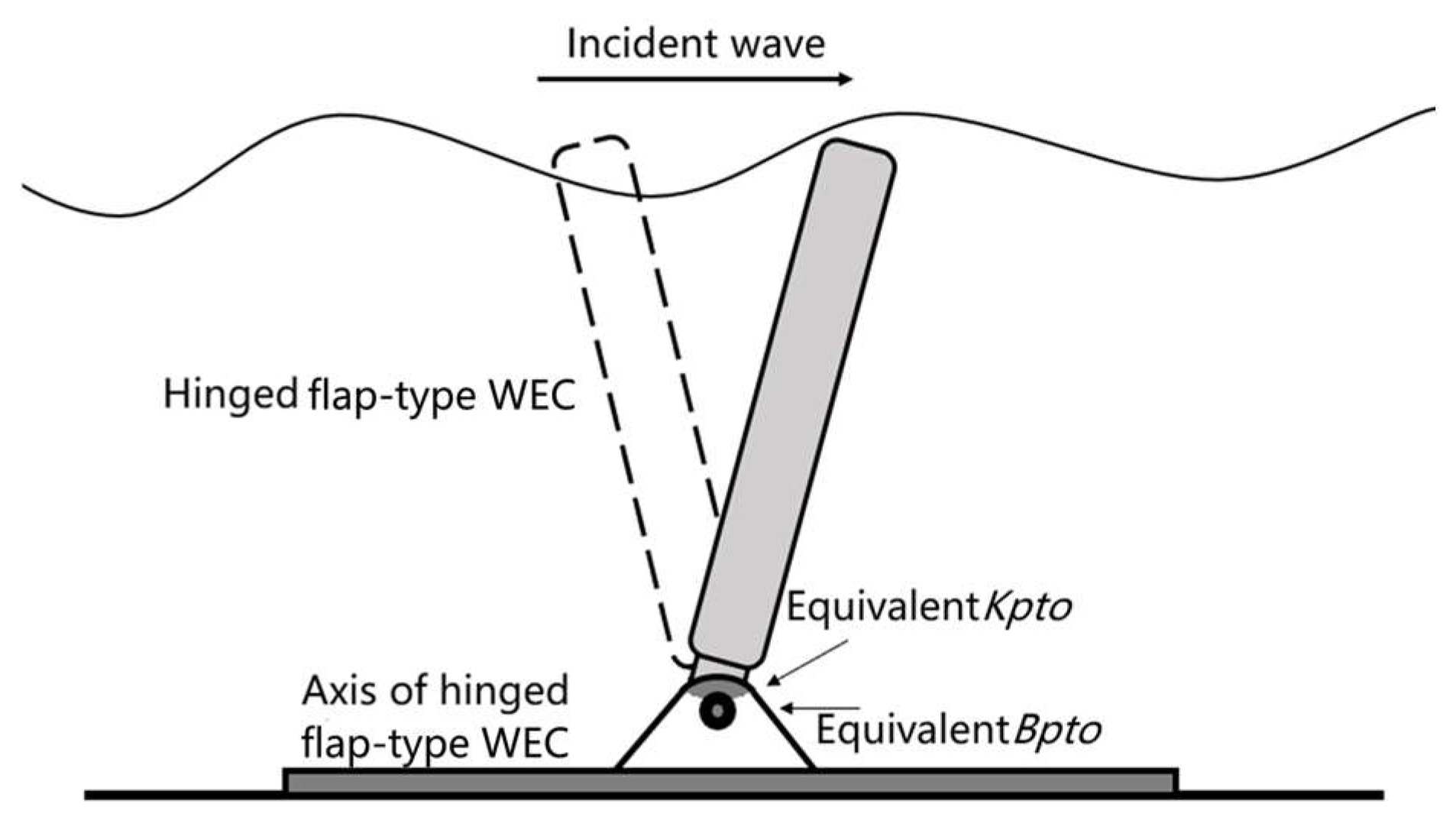
2.2. Hinged Motion of Floating Multi-Body Geometries

Articulation between structures refers to the physical connection of one structure to another through articulated joints. These connections are also called constraints, for the motion dynamics of the different bodies becomes constrained. Hinge constraints are characterized by new rotational degrees of freedom (DOF), whereas there is no relative translation motion at the hinge joint. Hinges can be categorized into spherical hinges, cross hinges and column hinges according to the constraining modes. Flap-type WECs are constrained by column hinges, whereas the initial position of the devices normally corresponds to the inverted pendulum position.
At this point, it is important to introduce the local coordinate system N 1 , centered at the hinge joint, different from the global coordinate system N 2 . There is always a transpose matrix E that makes the following equation hold:
N 1 = E N 2   ,
where E consists of a line vector e 1 , e 2 , e 3 .
In this paper, the relative motion between the flap-type WEC and the FOWT is given by the rotation around the local coordinate system x-axis, thus the constraint boundary condition is given by
H j U j H k U k = E T E T R j 0 G T U j E T E T R k 0 G T U k = 0 ,
where H is the boundary condition matrix of the constraint
G = 0 e 12 e 13 0 e 22 e 23 0 e 32 e 33 .
By invoking Equation (5), the equation of motion of the floating multi-body geometry can be expressed as follows [33]:
K j j K j k - H j T K k j K k k H k T H j - H k 0 U j U k R C = F j F k 0 ,
where F j and F k are the complex wave excitation forces on the first floating body and the second floating body, respectively; U j and U k are the frequency domain RAOs of the first floating body and the second floating body in the constrained multi-body configurations, respectively; R C is the constraint reaction force/moment matrix acting on the structure at the articulation axes; and K j j , K j k , K k j and K k k are the total stiffness matrixes of the floating bodies in the multi-body configuration, which can be expressed as follows:
K j j K j k K k j K k k = - ω 2 M j j 0 0 M k k + A j j ( ω ) A j k ( ω ) A k j ( ω ) A k k ( ω ) + i ω B p t o B p t o B p t o B p t o + B j j ( ω ) B j k ( ω ) B k j ( ω ) B k k ( ω ) + C j j 0 0 C k k + K p t o K p t o K p t o K p t o ,
where K p t o is the equivalent stiffness matrix of the PTO; and B p t o is the equivalent damping matrix of the PTO.

2.3. WEC Power Generation Evaluation

The flap-type WEC generates electrical power by the use of PTO systems, thus the absorbed energy is reflected on the work performed by the PTO damping force. For a linear damper, the damping torque of the PTO system is directly proportional to the rotating speed of the flap; thus, the frequency domain average power generation can be expressed as follows [16]:
P p t o = 1 T 0 T B p t o θ ^ 2 d t = 1 2 B p t o ω 2 θ 2 .
The natural periods of a mechanical system are related to the intrinsic parameters of the system itself. When the excitation period is close to the natural period, resonance shall occur. That is also applicable to the flap-type WEC, and the natural period of the flap DOF can be expressed as follows:
T = 2 π ω 0 = 2 π M + A ( ω 0 ) C + K p t o .
where ω 0 is the natural frequency; C is the hydrostatic stiffness; and K p t o is the PTO stiffness.
There is an optimal damping B e p t o , which leads the captured wave energy to its highest efficiency at a specific wave frequency. For the flap-type WEC in this paper, the optimal PTO damping can be expressed as follows:
B e p t o = [ ( C / ω ) ω ( M + A ( ω ) ) ] 2 + B ( ω ) 2
Another important performance parameter related to wave energy absorption is the capture width, C w :
C w = P p t o W E D ,
where D is the width of the flap-type WEC; and W E is the incident wave energy on a unit-width sectional area, which can be expressed as follows:
W E = 1 4 ρ g A 2 C v 1 + 2 k d 0 sinh 2 k d 0 ,
where g is the acceleration of gravity; A is the wave amplitude; k is the wave number of the incident wave; d 0 is the water depth, which equals to 250 m throughout this paper; and C v is the speed of the incident wave.
In actual sea conditions, sea elevation is random and does not correspond to sinusoidal waves. Thus, the concept of a wave spectrum is introduced to describe the probability distribution of sea waves, and the methods of spectral analysis are also applicable to the evaluation of wave power generation devices.
The shape of an ocean wave spectrum is related to its generation mechanism. At present, the most commonly used wave spectra are the JONSWAP spectrum, Pierson–Moskowitz spectrum and Bretschneider spectrum. This paper considers the JONSWAP spectrum; therefore, the wave spectral density function S ( f ) is given by
S ( f ) = α H s 2 T p 4 f 5 exp [ 5 4 ( 1 T p f ) 4 ] χ exp [ ( T p f 1 ) 2 2 σ 2 ] ,
where H s is the significant wave height; χ is the peak enhancement factor, and equals to 3.3 in this paper; T p is the wave peak period; f is the wave frequency; σ is the peak shape parameter; and α is a parameter related to χ , which can be expressed as follows:
a = 0.0624 0.23 + 0.0336 χ 0.185 / ( 1.9 + χ ) .
Given the sea state parameters, namely, H s , T p and χ , the power spectrum density (PSD) of the sea waves that is given by Equation (17) allows to obtain the probability of individual waves. Thus, it is also possible to obtain the expected power W Q in actual sea states within the frequency domain, which is given by Wen et al. [34]:
W Q = P p t o ( ω ) Q ( ω ) H Q ( ω ) ,
where Q is the occurrence probability of each frequency; and H Q is the average wave height of each frequency.

3. Hydrodynamic Modeling and Analysis

First, the schematic diagrams and related parameters of the bottom-fixed flap-type WEC (single-flap WEC) and the floating wind-flap platform (FWFP) hybrid configuration are given. Further in this section, the frequency domain hydrodynamic forces acting on the single-flap WEC and FWFP are calculated by the state-of-the-art software Ansys AQWA® and analyzed in detail.

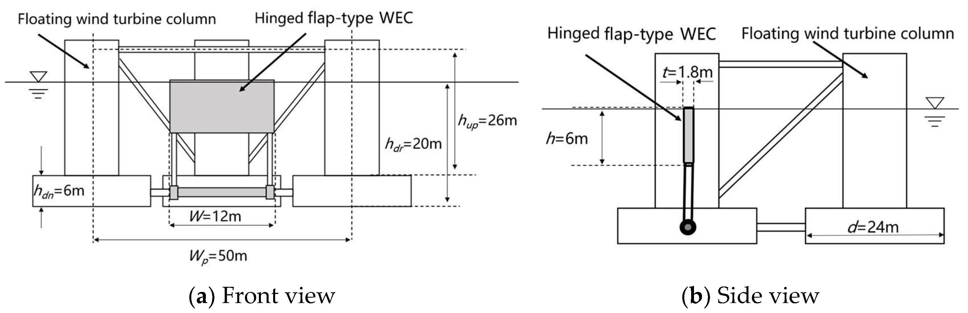
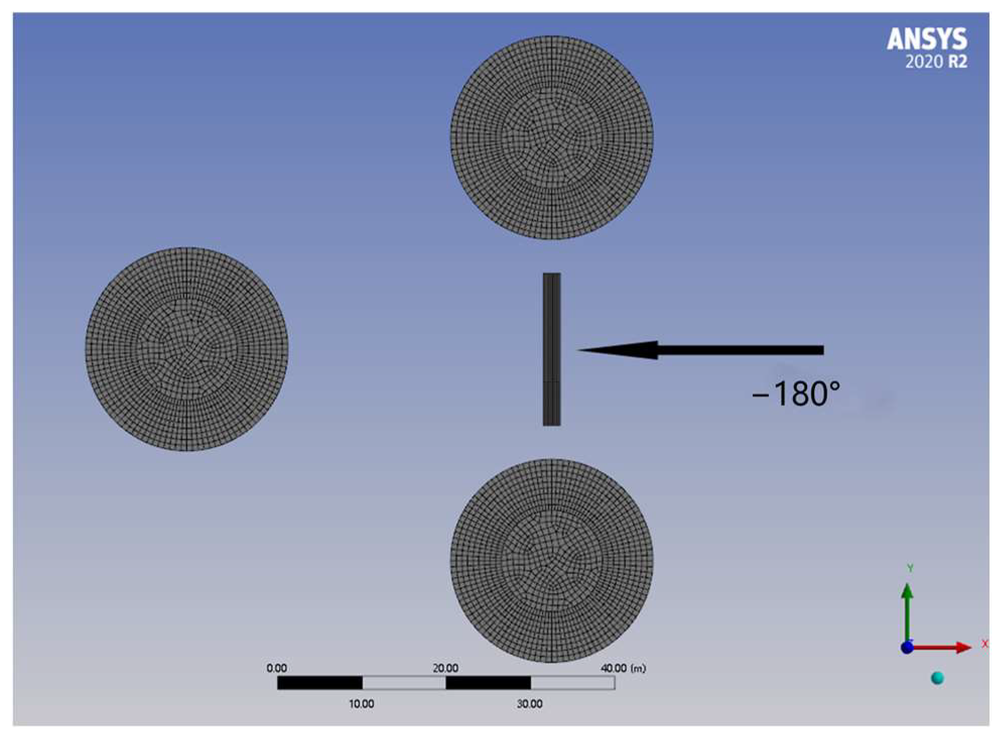
3.1. WEC and Multi-Body Geometries

The WEC generates power from the relative pitch motion around the axis of the hinge. Due to the hinge constraint, the mechanical coupling between the different rigid bodies affects many motion DOF and cannot be ignored. This paper adopts a 6-DOF model for the coupled motion. The hydraulic motor, overflow valve, throttle valve and other parts of its power generation are abstracted as springs with a constant stiffness parameter and damping parameters. That said, the flap-type WEC geometric model is shown in Figure 1, and its parameters are summarized in Table 1.
The FOWT considered in the hybrid configuration is the well-known OC4 semi-submersible platform [35]. The hybrid configuration consisting of the FOWT and WEC is shown in Figure 2. Each column of the platform is composed of a large lower part that is 6 m in length below and a thinner but longer upper part that is 25 m high. A smaller column in the center of the platform carries a 5 MW wind turbine, and the columns are all interconnected by pontoons and cross braces. The parameters of the platform are summarized in Table 2.

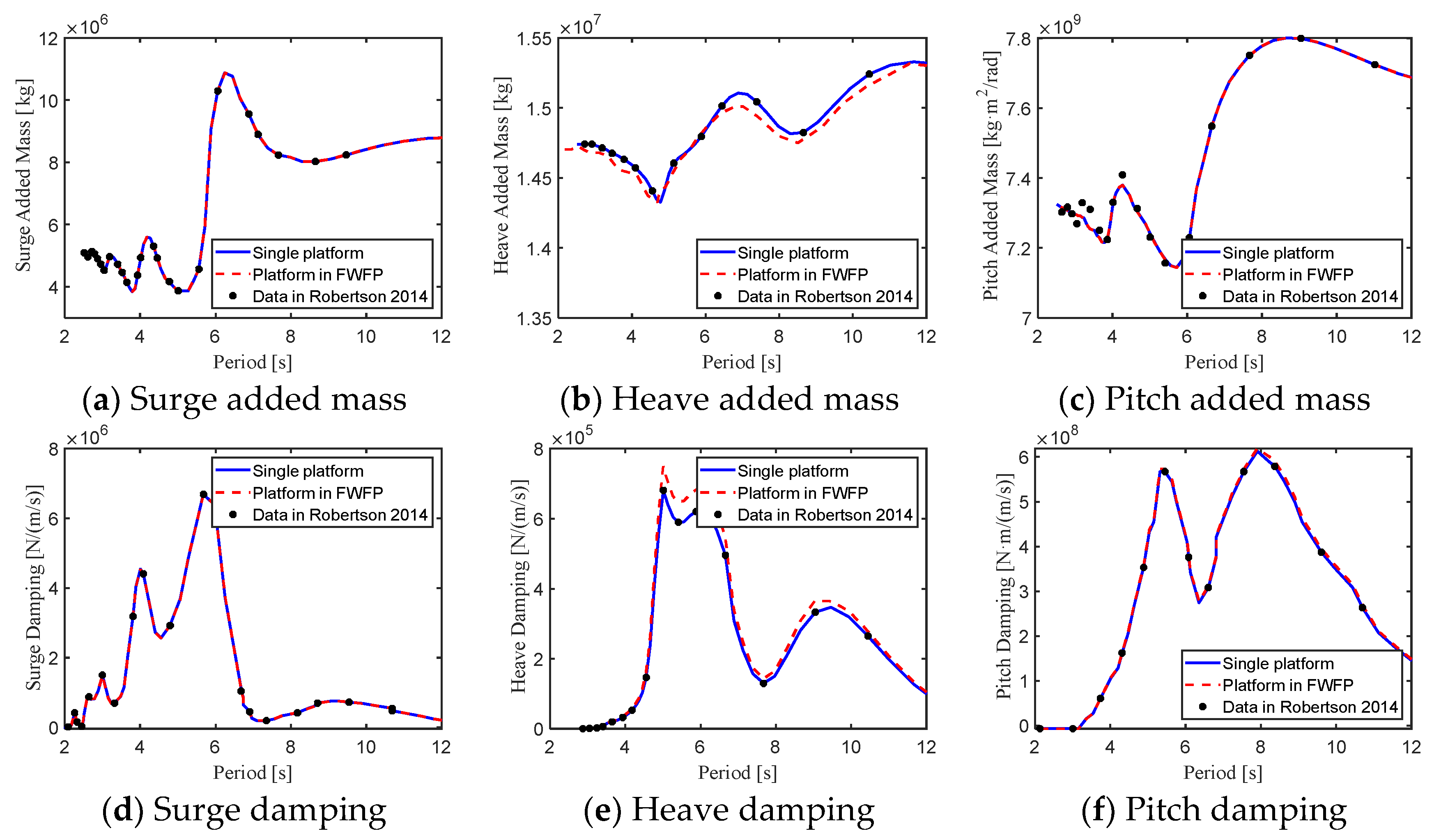
3.2. Multi-Body Hydrodynamic Analysis

Due to the close spacing between the WEC and the floating platform, complex hydrodynamic interference may occur, which affects the final motion characteristics and power generation. Therefore, it is necessary to analyze the resonance phenomenon of the FWFP.
As shown in Figure 3, in the hybrid configuration, the WEC is arranged at the −180° position, i.e., it is facing the waves. It is connected to the platform lower pontoon through the connecting rod and axis. As shown in Figure 3, compared with the platform, the scale of the WEC is small, so the characteristic mesh size of the WEC is 0.2 m in the process of grid division, while the grid of the platform is 1.2 m.
Figure 4 shows the hydrodynamic coefficients of added mass and radiation damping for the single-flap WEC and for the WEC in the FWFP hybrid configuration. Due to symmetry, surge, heave and pitch are the most relevant DOF. In Figure 4a–c, the added mass results of the single-flap present a smooth trend in the low-frequency range, whereas for wave periods below T = 2 s, it is possible to consider the added mass of the WEC stable. However, for the flap in the hybrid configuration, strong hydrodynamic interference occurs in wave periods between T = 2 and T = 4 s. Considering Equation (5), it is concluded that the resonant modes appear at n = 4, 5, 6, 7. In addition, the resonant behavior is small in the mode of heave but much more significant in the modes of surge and pitch. According to Zou et al. [36], it is possible to predict the resonant behavior more reasonably by using the external damping lid method embedded in AQWA®. AQWA applies an additional damped free surface boundary condition on the free surface of the gap fluid. This boundary condition is based on the widely used wave-absorbing beach method in the fully nonlinear time domain hydrodynamic model, but the value of the damping factor needs to be properly selected. In this paper, the resonance gap is not a regular rectangle, and the multi-body hydrodynamic resonance effect is not very overpredicted, so the external damping lid method is not used in this paper. In Figure 4d–f, similar conclusions are drawn regarding radiation damping, though the curve converged to 0 in the high-frequency range. Moreover, the effects of hydrodynamic interference seem to be stronger on the damping values when compared to the added mass values.
In Figure 5, the numerical simulations presented in this paper are validated with the results given by Robertson et al. [35]. The curves shown in Figure 5 correspond to the single-body simulations of the OC4 semi-submersible platform, plus the hydrodynamic coefficients of the platform in the FWFP hybrid configuration. The results are stable in the high-frequency range, this time for wave periods below T = 2.5 s. It is also possible to conclude from Figure 5 that the hydrodynamic interaction between the flap-type WEC and FOWT is much stronger for the WEC, for there is no significant difference between the curves drawn for the single-body platform and the platform of the FWFP hybrid configuration.

4. Power Optimization Based on the Frequency Domain Model

In this chapter, the parameter optimization of the power generation of the bottom-fixed flap-type WEC and floating hinged WEC is carried out. First, based on the hydrodynamic results of the frequency domain, the hinge connection is introduced, and the motion of the WEC is verified by the multi-DOF articulated model. Then, the parameters affecting the natural frequencies and optimal damping are analyzed in order to obtain the optimal parameters of the PTO system. By combining the parameter optimization with the random wave characterization of the specific operation site in the South China Sea, the parameters are finally optimized considering the objective of maximum absorbed power.

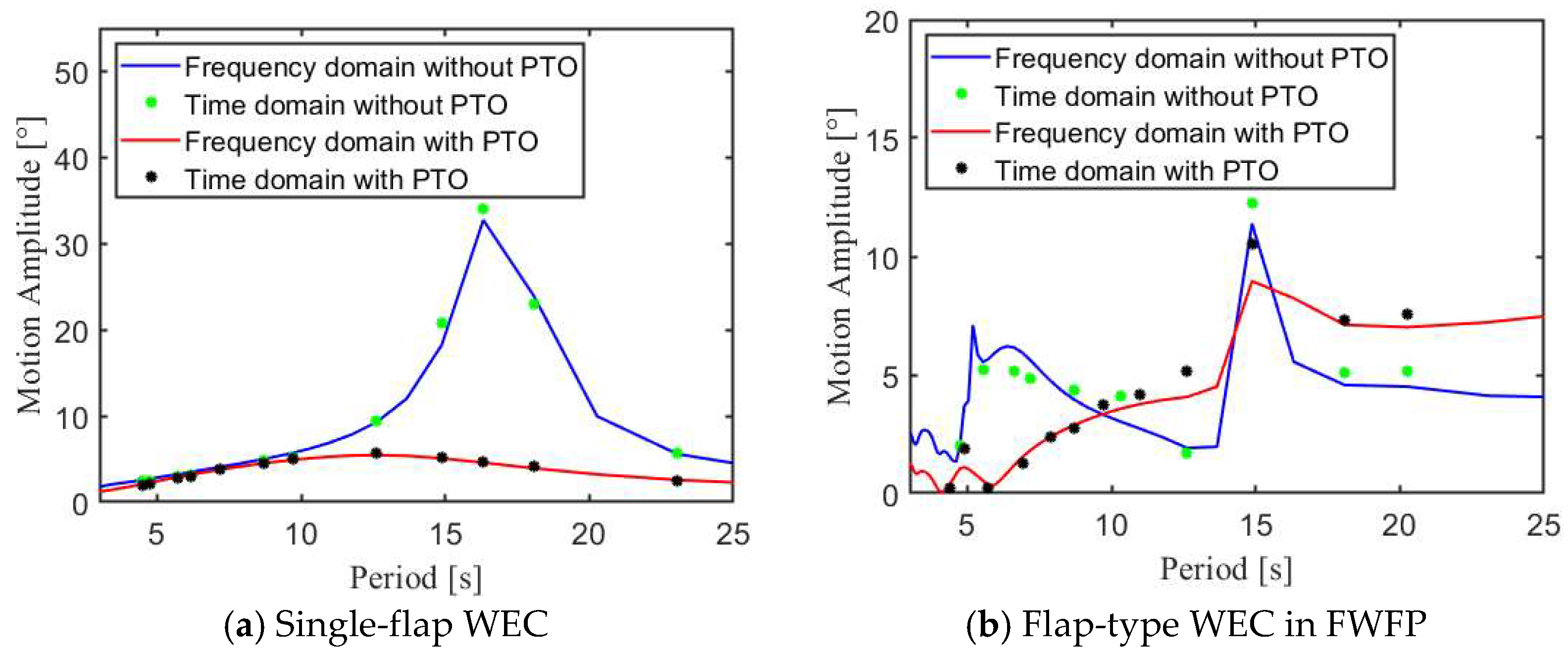
4.1. Verification of the Multi-Body Formulation

The validity of the coordinate transform given by Equation (7) and the RAO evaluation of the multi-body geometry given by Equation (10) is verified by comparing the frequency domain responses with the time domain responses simulated in AQWA®. Because the evaluations are performed around the centroids of the two floating bodies, linearity of motion is assumed, and therefore it must be verified.
First, the correctness of the hinged constraint matrix is verified by setting the stiffness parameter and damping parameter of the PTO at 0. The results of the single-flap are plotted in Figure 6a, which show very consistent trends. The peak values given by AQWA® are slightly higher than the frequency domain results, especially when PTO damping is added to the model. That is a consequence of the convolution term of the Cummins equation embedded in the time domain simulations. Second, the correctness of the PTO system is verified by setting Kpto to 1 × 10⁷ N·m/rad and Bpto to 1 × 10⁸ N·m/(rad/s). The PTO forces change the trend and peak amplitude of motion—the amplitude decreases, and the peak frequency shifts to a higher frequency.
Figure 6b shows the results for the flap-type WEC in the FWFP hybrid configuration. Verification is also accomplished by setting Kpto to 1 × 10⁷ N·m/rad and Bpto to 1 × 10⁸ N·m/(rad/s). Different trends are observed in the high-frequency and low-frequency ranges after adding the PTO. At high frequency, because the motion of the floating platform is small, the mechanical coupling should not affect the WEC significantly, though there are differences between the single-flap and hybrid configuration curves, which shall be explained according to pure hydrodynamic coupling. After adding the PTO, the changes in the WEC response in the high frequency are similar to the case of the single flap, namely, the peak response decreases, and the peak frequency is shifted toward a higher frequency. At low frequency, the floating platform moves greatly, and both hydrodynamic and mechanical coupling are brought into action. While the PTO damping decreases slightly the peak response near T = 15 s, the resonant mode is kept at the same frequency, whereas for lower frequencies, the addition of PTO forces leads the WEC response to a higher amplitude of motion.

4.2. Natural Period Optimization

When external excitation occurs at a frequency near the natural frequency of a hydrodynamic system, the amplitude of the motion will increase significantly [37]. This phenomenon is called “resonance”, and the expression “resonance frequency” stands for the value of the frequency within which resonance occurs.
The average period of the waves in the South China Sea is mainly distributed within 4~6 s [38]. By adjusting the parameters, the natural frequency of the system can approximate the wave frequency, which can significantly improve the performance of the WEC. That may be accomplished by changing the stiffness parameter of the PTO, Kpto, which has a greater influence on the natural periods of both the single-flap WEC and the WEC in the FWFP hybrid configuration.
Thus, a systematic study is conducted with the WEC density ranging from 0.3 to 0.6 t/m3 and 40 Kpto cases within the interval 0~8 × 10⁷ N·m/(rad/s). Figure 7 displays the results of the optimization in colorful diagrams. As shown in Figure 7a, the natural period of the single-flap WEC presents smooth trends, and the natural period of the WEC may be increased by increasing both the density and/or Kpto parameter.
On the other hand, Figure 7b shows that the overall changes of the natural period of the flap-type WEC when in the FWFP configuration normally relate in a nonlinear way with an increase in the Kpto parameter. That happens mainly due to the hydrodynamic interaction with the floating platform, given the high frequency of the natural period. Due to hydrodynamic interference, added mass and damping oscillates around 2~4 s, and there are more oscillations at 3.5~4.5 s, as it is clear from Figure 7b.

4.3. Optimal Damping Optimization

According to the results obtained in Figure 7 and the distribution of wave periods in the South China Sea, different Kpto parameters are selected for different WEC densities. The selected parameters are shown in Table 3 and give natural periods around 4.0~5.5 s.
The optimal damping ratio of the flap-type WEC can be obtained from Equation (14), but it cannot evaluate the energy capture variation trend in each frequency, so the energy capture efficiency in each case is calculated from Equation (15). Figure 8a,c,e,g shows the capture width ratio ( C w ) of the single-flap WEC in different scenarios. In those plots, the energy capture efficiency around 4~6 s is high, and the equivalent Bpto of the system should be around 2~6 × 10⁸ N·m/(rad/s). Different densities mainly affect the capture width in the low-frequency range: under the same Bpto parameters, the higher the density, the higher the capture width in low-frequency waves. Then, Figure 8b,d,f,h shows the capture width ratio of the flap-type WEC in the FWFP in different scenarios as well. For the flap-type WEC in the FWFP configuration, the main period of capturing wave energy is 4.5 s or less. That is because the hinged coupled motion of the multi-body geometry changes the motion characteristics, and at the same time, hydrodynamic interference makes the WEC have a higher energy capture efficiency at high frequencies. The maximum capture width is observed at around 3~4.5 s, and the equivalent Bpto should be around 0.5~1.5 × 10⁸ N·m/(rad/s). Again, the density of the WEC mainly affects the capture efficiency at low frequency.

4.4. Comparative Optimization of Power Generation

In the previous section, the optimal damping under different densities and Kpto was investigated. In this section, the frequency domain power generation is further compared according to the optimal damping parameters obtained. At the same time, in order to make the results more accurate, the range of Kpto values is extended, according to the values shown in Table 4.
The average power generation under each parameter condition is calculated according to Equation (12). In Figure 9 legends, the term single stands for the single-flap WEC, and the legend double stands for the WEC in the FWFP configuration. Figure 9a shows the frequency domain average power generation from LC1 to LC3. The peak power of the single-flap WEC is about 1.5 × 10⁵ W, for a peak period of T = 6 s, whereas the WEC in the FWFP configuration has two peaks, one at T1 = 4.8 s and the other at T2 = 11 s—the first peak corresponds to the natural period of the WEC itself, and the second peak is caused by the constructive interaction between the two floating bodies.
The results for the other parameters shown in Figure 9b–d are similar to those in Figure 9a. The parameters with the highest power generation are LC2-single, LC2-double, LC5-single, LC6-double, LC8-single, LC8-double, LC10-single and LC11-double. That is mostly consistent with the working conditions selected in Table 3; therefore, the optimization method based on natural periods and optimal damping can, indeed, increase WEC power generation to the highest levels.

4.5. Wave Absorbed Power Optimization

Because sea waves are rarely sinusoidal, i.e., they do not move regularly according to a certain frequency and wave height but show randomness, the parameter optimization presented in the last section may not be reasonable enough. According to the random distribution of sea waves, the expected wave absorbed power of the WEC should be calculated in the form of probability expectation. Thus, Equation (19) is invoked to guide the investigation to a further parameter optimization.
The South China Sea is a prospective area for the deployment of FOWTs and has been considered an object of study for the implementation of up to 15 MW wind turbines [39]. The probability distributions of the annual averaged significant wave height ( H s ) and wave averaged period ( T a v ) in the South China Sea are given in Table 5. The scatter diagram is constructed with data from January 1988 to December 2011 [34]. According to Zheng et al. [40], a good estimation for the wave peak period is given by T p = 1.2 T a v . In Figure 10, the JONSWAP spectrum is given for H s = 0.5 m, T p = 5.4 s, and χ = 3.3.
The expected power in each parameter condition is calculated by Equation (19). Figure 11a shows the expected power for LC1 to LC3. The expected power of the single-flap WEC and the WEC in the FWFP is close under LC2 and LC3, while the expected power of the single-flap WEC under LC1 is much larger than that of the WEC in the FWFP. In Figure 11b,c, the expected power for LC4 to LC9 presents similar trends to that of LC1 to LC3. Then, Figure 11d shows the expected power for LC10 to LC12. Under LC10 and LC11, the expected power of the single-flap WEC and the WEC in the FWFP are close, while under LC12, the expected power of the single-flap WEC is less than the WEC in the FWFP configuration.
In comparison, the highest power for the single-flap WEC is found under LC4, where the WEC is absorbing 3.34 × 10⁴ W from sea waves, and the highest wave absorbed power for the flap-type WEC in the FWFP configuration is found under LC6, where the WEC obtains a power of 3.18 × 10⁴ W.
The results show that, although there is a big difference in the frequency domain power generation curves between the single-flap WEC and the flap-type WEC in the FWFP due to the coupled hydrodynamic interaction, there is actually little difference with regard to the expected wave absorbed power when operating in the South China Sea. That is most likely due to the relatively small periods of waves in the location, whereas the wind-flap configuration may perform differently in other regions.

5. Conclusions

In this paper, the motion response and power generation of two models, namely, a bottom-fixed flap-type WEC and the same flap-type WEC in a floating wind-flap platform combination for hybrid power, are discussed. Based on the in-house frequency domain model and Ansys AQWA® simulations, the complex mechanical and hydrodynamic interactions between the WEC and floating platform were analyzed in detail. The frequency domain model that accounts for the hinge constraints and multi-body interactions was validated with the time domain results given by AQWA®. The linear formulation was also verified given the case where the PTO forces are not brought into action. The different models calculated the natural frequencies of the system, which provided a reference for the value of optimal Kpto. Furthermore, the optimal PTO damping parameter and density were also optimized, with the objective of maximizing the capture width of the WEC. Finally, the average power generation was calculated, and the specific optimal values of the two models were investigated by setting different loading conditions and taking the expected wave absorbed power as the ultimate optimization goal. The following conclusions can be drawn from this study:
(1)
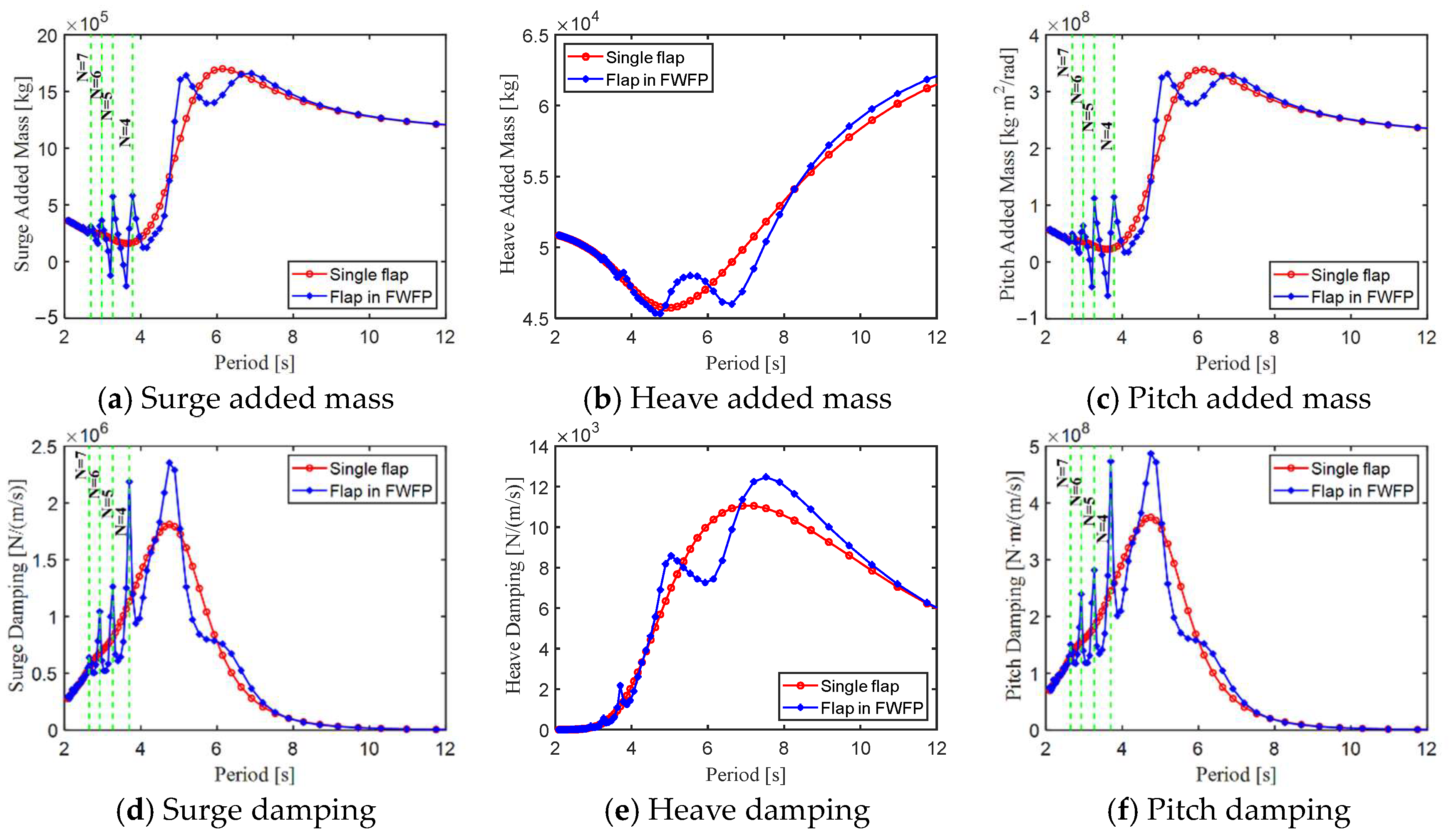
The effects of hydrodynamic interaction in the hybrid configuration can be neglected for the floating platform. It has a great influence on the flap-type WEC; the resonant behavior is small in the mode of heave but much more significant in the modes of surge and pitch, especially at high frequencies. Even if the gap between the two floating bodies considered is not a regular rectangle, the resonant modes in Equation (5) and the observed resonance frequencies are still consistent at the high frequency.
(2)
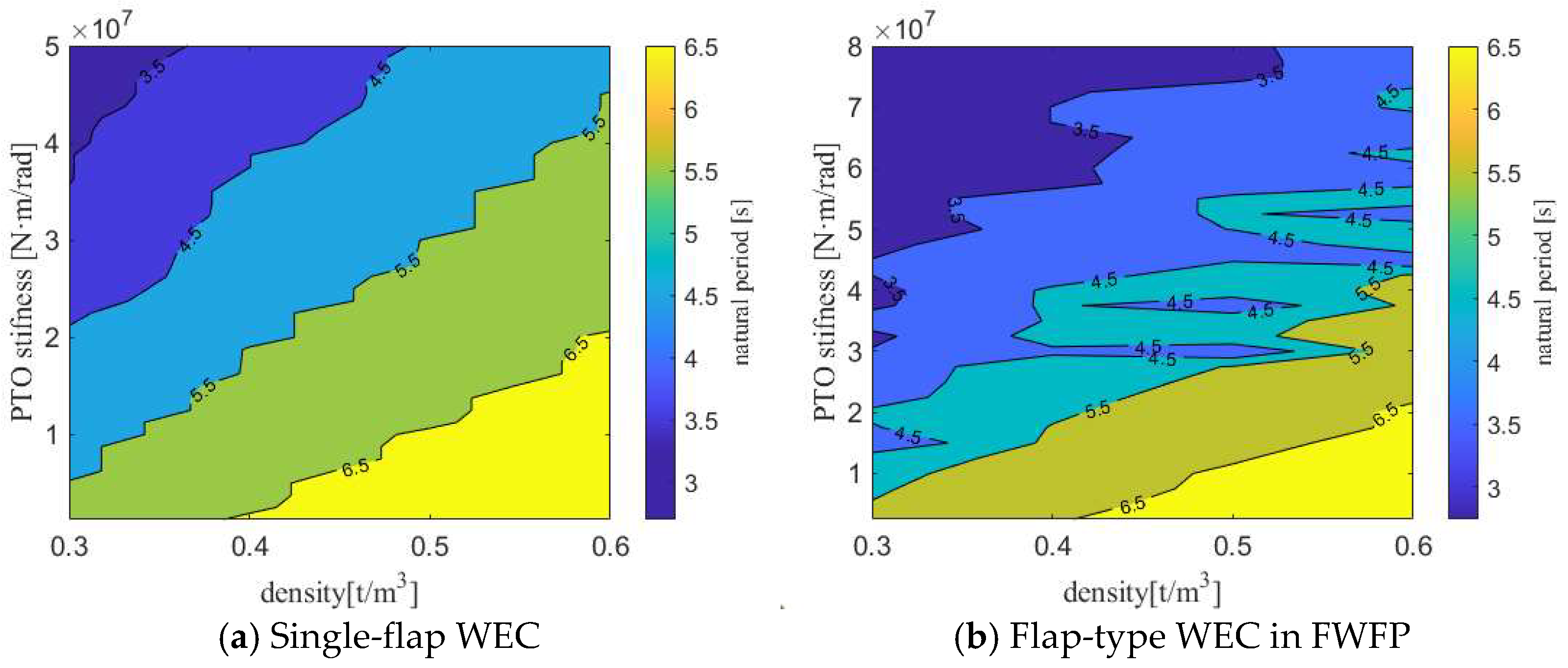
With an increase in density, the natural period of the flap-type WEC increases for both single-flap and FWFP configurations. The natural frequencies also increase with Kpto. The observed trends are rather smooth for the single-flap WEC, mainly due to the smooth behavior of the hydrodynamic coefficients of the WEC. The natural frequencies of the flap-type WEC in the FWFP configuration present a similar trend; the natural period of the flap-type WEC when in the FWFP configuration normally relates in a nonlinear way with an increase in the Kpto parameter. However, due to the hydrodynamic interaction between the different floating bodies, WECs’ added mass and damping oscillate at the wave periods around 2~4 s and that is reflected in the natural period of the WEC when modifying the PTO parameters around the same wave periods.
(3)
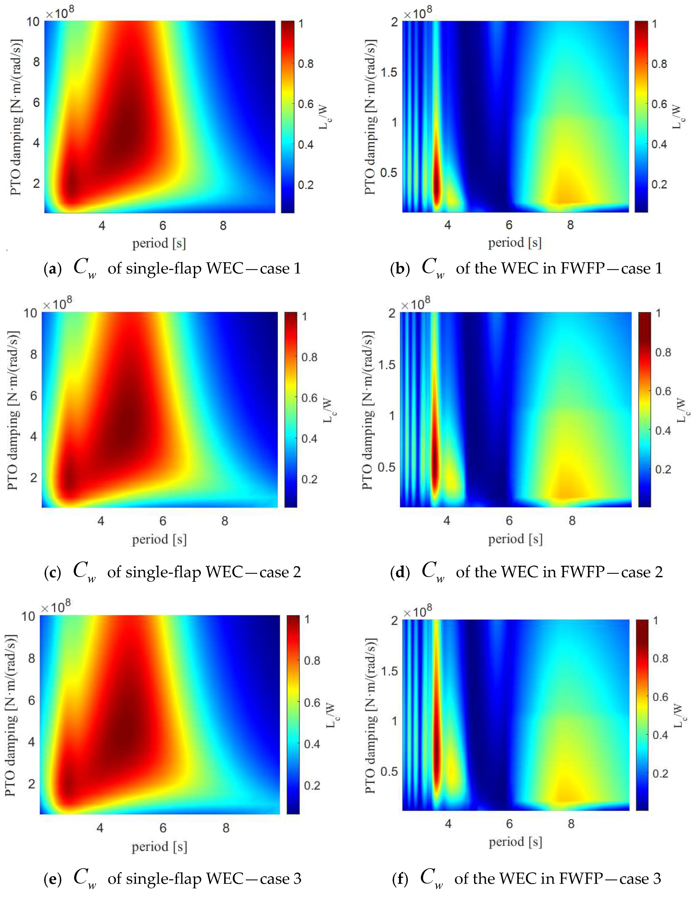
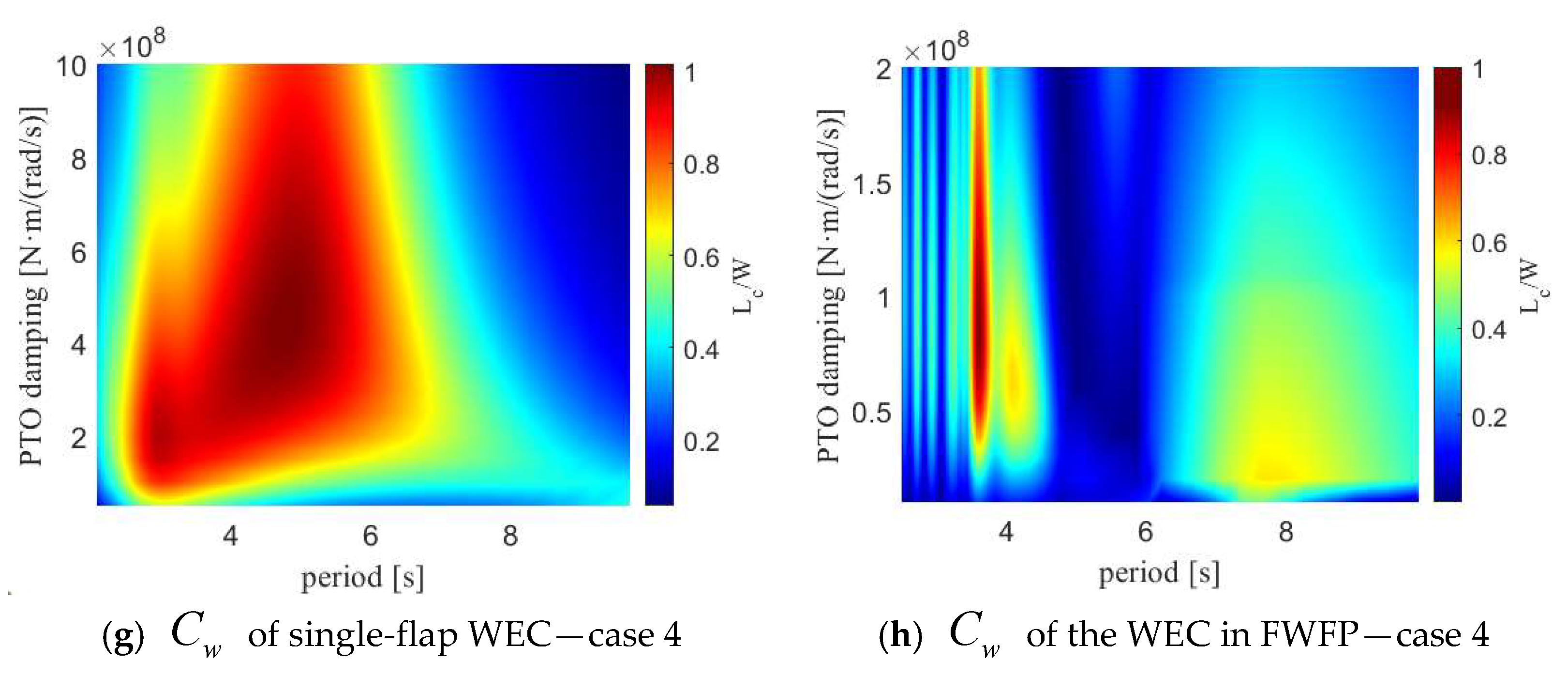
The flap-type WEC considered in this paper has a high capture width in the range of a 4~6 s wave period. However, after it is combined with the floating platform, there is a main wave frequency where the WEC is capturing a significant amount of wave energy, which is due to the multi-body coupling and shifts the peak of absorbed power to a higher frequency. Due to the influences of the floating platform, the WEC presents a small peak at around a 7~10 s wave period. In addition, under the same Bpto parameters, the higher the WEC density, the higher the capture width at low frequencies.
(4)
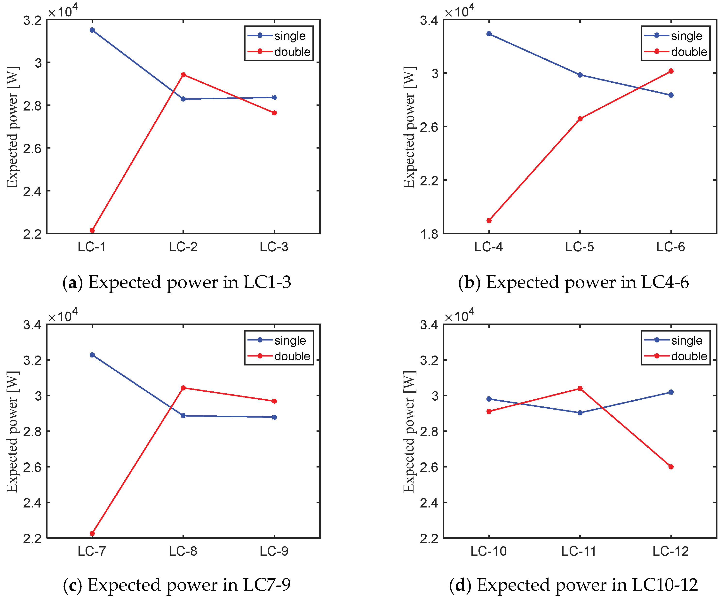
The parameter optimization results obtained are mostly applicable to the different working conditions considered, for both the natural period optimization and optimal damping method. Although the single-flap WEC and the flap-type WEC in the FWFP present quite different responses in the frequency domain regarding wave power generation, the expected amount of wave absorbed power is actually similar when employed at the same operation site in the South China Sea.
It must be noted that the flap-type WEC in this paper has not been modified to account for viscosity effects, which may lead to inaccurate potential flow results. In addition, the frequency domain model developed does not account for nonlinear PTOs, mooring effects or nonlinear constraints. Those effects may be further considered. However, it is necessary to develop a time domain program to analyze the FWFP with those nonlinear effects in action.

Author Contributions

M.C.: investigation, methodology, software, writing—original draft, funding acquisition, resources; Q.Y.: investigation, methodology, software, data curation, writing—original draft; T.S.H.: methodology, software, data curation, writing—original draft; H.Z.: conceptualization, supervision, methodology, writing—review and editing; K.Z.: conceptualization, investigation, data curation, validation; Y.Y.: investigation, methodology, data curation, software, formal analysis; T.T.: data curation, software, validation, writing—original draft; S.L.: data curation, software, funding acquisition, resources, writing—review and editing; W.J.: funding acquisition, resources, project administration, writing—review and editing; C.L.: project administration, resources, funding acquisition, data curation, writing—review and editing. All authors have read and agreed to the published version of the manuscript.

Funding

This research was supported the National Natural Science Foundation of China, grant number 52171275. The work presented in this paper is part of the project “Key technology research and demonstration project of 10 MW deep-sea floating offshore wind turbine (DTGD-2023-10174)—Key technology research task of floating offshore combined wind and wave power generation” supported by Guangdong Datang International Chaozhou Power Generation Co., Ltd., Chaozhou 515700, China.

Institutional Review Board Statement

Not applicable.

Informed Consent Statement

Not applicable.

Data Availability Statement

Data are contained within the article.

Conflicts of Interest

Authors Yi Yang, Tao Tao, Shi Liu were employed by the company China Southern Power Grid Technology Co., Ltd. Author Wei Jiang was employed by the company China Datang Corporation Ltd. Author Changjie Li was employed by the company Guangdong Datang International Chaozhou Power Generation Co., Ltd. The remaining authors declare that the research was conducted in the absence of any commercial or financial relationships that could be construed as a potential conflict of interest.

Nomenclature

ϕ Total velocity potential [-] C w Capture width [-]
ϕ 0 Incident potential [-] D The width of the flap-type WEC [m]
ϕ s Diffraction potential [-] W E Incident wave energy in a unit-width sectional area [W]
ϕ r Radiation potential [-] g The acceleration of gravity [m/s2]
f ^ e x c Complex wave excitation force [N] A Wave amplitude [m]
A i j ( ω ) Added mass coefficient matrix [-] k Wave number [-]
B i j ( ω ) Radiation damping coefficient matrix [-] d 0 Water depth [m]
ρ Water density C v Incident wave speed [m/s]
S M B The wet surface of the floating body [m2] S ( f ) Wave spectral density function [-]
d The gap between two floating bodies [m] H s Significant wave height [m]
λ n The wavelength associated with the resonant mode [-] χ Peak enhancement factor [-]
X Frequency domain response amplitude operator matrix [-] T p Wave peak period [s]
M Rigid-body mass-inertia matrix [-] f Wave frequency [rad/s]
C Hydrodynamic restoring matrix [-] σ Peak shape parameter [-]
N 1 Local coordinate system [-] W Q Expected power [W]
N 2 Global coordinate system [-] Q The occurrence probability of each frequency [-]
E Transpose matrix [-] H Q The average wave height of each frequency [m]
e 1 , e 2 , e 3 The unit vectors of the local articulation axes with respect to the global axes [-]Abbreviations
H The boundary condition of the constraint matrix [-]FOWTFloating offshore wind turbine
F Complex wave excitation force matrix [-]STCSpar–torus combination
U Frequency domain RAO matrix in constrained multi-body configurations [-]WECWave energy converter
R C Constraint reaction force/moment matrix acting on the structure at the articulation axesOWCOscillating water column
K Total stiffness matrixes [-]PTOPower take-off
K p t o Equivalent stiffness matrix of the PTO [-]FWFPFloating wind-flap platform
B p t o Equivalent damping matrix of the PTO [-]RAOResponse amplitude operator
P p t o Frequency domain average power generation [W]DOFDegrees of freedom
T Natural period [s]PSDPower spectrum density
ω 0 Natural frequency [rad/s]

References

  1. International Energy Agency. Renewables 2023; International Energy Agency: Paris, France, 2023. [Google Scholar]
  2. Bashetty, S.; Ozcelik, S. Review on dynamics of offshore floating wind turbine platforms. Energies 2021, 14, 6026. [Google Scholar] [CrossRef]
  3. GWEC. Global Wind Energy Council (GWEC). Available online: http://www.gwec.net/ (accessed on 4 September 2023).
  4. Shin, H. Model test of the OC3-Hywind floating offshore wind turbine. In Proceedings of the ISOPE International Ocean and Polar Engineering Conference, Maui, HI, USA, 19–24 June 2011; ISOPE: Mountain View, CA, USA,, 2011. [Google Scholar]
  5. Jacobsen, A.; Godvik, M. Influence of wakes and atmospheric stability on the floater responses of the Hywind Scotland wind turbines. Wind Energy 2021, 24, 149–161. [Google Scholar] [CrossRef]
  6. China Offshore Wind Association. The World’s First Anti-Typhoon Floating Unit Connected to the Grid for Power Generation. Available online: https://www.chinaoffshorewind.cn/html/en/NEWS/DYNAMICS/20211213/265.html (accessed on 8 December 2023).
  7. People’s Daily Online-China. China’s First Deep-Sea Floating Wind Power Platform “Haiyou Guanlan” Was Successfully Connected to the Grid and Put into Operation. Available online: http://finance.people.com.cn/n1/2023/0520/c1004-32690779.html (accessed on 9 September 2023).
  8. Xinhua-China. China’s Large Floating Wind Power Platform “Mingyang Tiancheng” Will Be Put into Operation. Available online: http://www.news.cn/tech/20240712/e9035cde01ba46dc9f3994afb99a57e8/c.html (accessed on 12 July 2024).
  9. Castro-Santos, L.; Martins, E.; Soares, C.G. Cost assessment methodology for combined wind and wave floating offshore renewable energy systems. Renew. Energy 2016, 97, 866–880. [Google Scholar] [CrossRef]
  10. Laura, C.-S.; Vicente, D.-C. Life-cycle cost analysis of floating offshore wind farms. Renew. Energy 2014, 66, 41–48. [Google Scholar] [CrossRef]
  11. Slocum, A.; Kluger, J.; Mannai, S. Energy harvesting and storage system stabilized offshore wind turbines. In Proceedings of the 2019 Offshore Energy and Storage Summit (OSES), Brest, France, 10–12 July 2019; IEEE: New York, NY, USA, 2019. [Google Scholar]
  12. Muliawan, M.J.; Karimirad, M.; Gao, Z.; Moan, T. Extreme responses of a combined spar-type floating wind turbine and floating wave energy converter (STC) system with survival modes. Ocean Eng. 2013, 65, 71–82. [Google Scholar] [CrossRef]
  13. O’sullivan, K.P. Feasibility of Combined Wind-Wave Energy Platforms. Ph.D. Thesis, University College Cork, Cork, Ireland, 2014. [Google Scholar]
  14. Zhang, D.; Chen, Z.; Liu, X.; Sun, J.; Yu, H.; Zeng, W.; Ying, Y.; Sun, Y.; Cui, L.; Yang, S.; et al. A coupled numerical framework for hybrid floating offshore wind turbine and oscillating water column wave energy converters. Energy Convers. Manag. 2022, 267, 115933. [Google Scholar] [CrossRef]
  15. Chen, M.; Xiao, P.; Zhou, H.; Li, C.B.; Zhang, X. Fully coupled analysis of an integrated floating wind-wave power generation platform in operational sea-states. Front. Energy Res. 2022, 10, 931057. [Google Scholar] [CrossRef]
  16. Chen, M.; Deng, J.; Yang, Y.; Zhou, H.; Tao, T.; Liu, S.; Sun, L.; Hua, L. Performance analysis of a floating wind–wave power generation platform based on the frequency domain model. J. Mar. Sci. Eng. 2024, 12, 206. [Google Scholar] [CrossRef]
  17. Ren, N.; Ma, Z.; Shan, B.; Ning, D.; Ou, J. Experimental and numerical study of dynamic responses of a new combined TLP type floating wind turbine and a wave energy converter under operational conditions. Renew. Energy 2020, 151, 966–974. [Google Scholar] [CrossRef]
  18. Tian, W.; Wang, Y.; Shi, W.; Michailides, C.; Wan, L.; Chen, M. Numerical study of hydrodynamic responses for a combined concept of semisubmersible wind turbine and different layouts of a wave energy converter. Ocean Eng. 2023, 272, 113824. [Google Scholar] [CrossRef]
  19. Zhao, H.-T.; Sun, Z.-L.; Hao, C.-L.; Shen, J.-F. Numerical modeling on hydrodynamic performance of a bottom-hinged flap wave energy converter. China Ocean Eng. 2013, 27, 73–86. [Google Scholar] [CrossRef]
  20. Calvário, M.; Gaspar, J.; Kamarlouei, M.; Hallak, T.; Soares, C.G. Oil-hydraulic power take-off concept for an oscillating wave surge converter. Renew. Energy 2020, 159, 1297–1309. [Google Scholar] [CrossRef]
  21. Michele, S.; Renzi, E. A second-order theory for an array of curved wave energy converters in open sea. J. Fluids Struct. 2019, 88, 315–330. [Google Scholar] [CrossRef]
  22. Michailides, C.; Luan, C.; Gao, Z.; Moan, T. Effect of flap type wave energy converters on the response of a semi-submersible wind turbine in operational conditions. In Proceedings of the International Conference on Offshore Mechanics and Arctic Engineering, San Francisco, CA, USA, 8–16 June 2014; American Society of Mechanical Engineers: New York, NY, USA, 2014. [Google Scholar]
  23. Si, Y.; Chen, Z.; Zeng, W.; Sun, J.; Zhang, D.; Ma, X.; Qian, P. The influence of power-take-off control on the dynamic response and power output of combined semi-submersible floating wind turbine and point-absorber wave energy converters. Ocean Eng. 2021, 227, 108835. [Google Scholar] [CrossRef]
  24. Celesti, M.L.; Paduano, B.; Peña-Sanchez, Y.; Pasta, E.; Faedo, N.; Ringwood, J.V. On the behaviour of a combined wind-wave energy conversion platform under energy-maximising control conditions. In Proceedings of the OCEANS 2023-Limerick, Limerick, Ireland, 5–8 June 2023; IEEE: New York, NY, USA, 2023. [Google Scholar]
  25. Ma, C.; Bi, C.-W.; Xu, Z.; Zhao, Y.-P. Dynamic behaviors of a hinged multi-body floating aquaculture platform under regular waves. Ocean Eng. 2022, 243, 110278. [Google Scholar] [CrossRef]
  26. Wang, L.; Ringwood, J.V. Control-informed ballast and geometric optimisation of a three-body hinge-barge wave energy converter using two-layer optimisation. Renew. Energy 2021, 171, 1159–1170. [Google Scholar] [CrossRef]
  27. Ren, N.; Zhang, C.; Magee, A.R.; Hellan, Ø.; Dai, J.; Ang, K.K. Hydrodynamic analysis of a modular multi-purpose floating structure system with different outermost connector types. Ocean Eng. 2019, 176, 158–168. [Google Scholar] [CrossRef]
  28. Chen, M.; Ouyang, M.; Guo, H.; Zou, M.; Zhang, C. A coupled hydrodynamic–structural model for flexible interconnected multiple floating bodies. J. Mar. Sci. Eng. 2023, 11, 813. [Google Scholar] [CrossRef]
  29. Chen, M.; Zou, M.; Zhu, L.; Ouyang, M.; Liang, Q.; Zhao, W. A fully coupled time domain model capturing nonlinear dynamics of float-over deck installation. Ocean Eng. 2024, 293, 116721. [Google Scholar] [CrossRef]
  30. Zhang, X.; Li, B.; Hu, Z.; Deng, J.; Xiao, P.; Chen, M. Research on size optimization of wave energy converters based on a floating wind-wave combined power generation platform. Energies 2022, 15, 8681. [Google Scholar] [CrossRef]
  31. Folley, M. Numerical Modelling of Wave Energy Converters: State-of-the-Art Techniques for Single Devices and Arrays; Academic Press: Cambridge, MA, USA, 2016. [Google Scholar]
  32. Lewandowski, E.M. Multi-vessel seakeeping computations with linear potential theory. Ocean Eng. 2008, 35, 1121–1131. [Google Scholar] [CrossRef]
  33. ANSYS AQWA Users Manual; ANSYS Inc.: Canonsburg, PA, USA, 2019.
  34. Wen, Y.; Wang, W.; Liu, H.; Mao, L.; Mi, H.; Wang, W.; Zhang, G. A shape optimization method of a specified point absorber wave energy converter for the south china sea. Energies 2018, 11, 2645. [Google Scholar] [CrossRef]
  35. Robertson, A.; Jonkman, J.; Masciola, M.; Song, H.; Goupee, A.; Coulling, A.; Luan, C. Definition of the Semisubmersible Floating System for Phase II of OC4; National Renewable Energy Lab. (NREL): Golden, CO, USA, 2014. [Google Scholar]
  36. Zou, M.; Chen, M.; Zhu, L.; Yun, Q.; Zhao, W.; Liang, Q.; Zhao, Y. Experimental and numerical investigation of gap resonances between side-by-side fixed barges under beam sea excitation. Ocean Eng. 2024, 297, 117150. [Google Scholar] [CrossRef]
  37. Ruezga, A. Buoy analysis in a point-absorber wave energy converter. IEEE J. Ocean. Eng. 2019, 45, 472–479. [Google Scholar] [CrossRef]
  38. Zhang, N.; Zhang, X.; Xiao, L.; Wei, H.; Chen, W. Evaluation of long-term power capture performance of a bistable point absorber wave energy converter in South China Sea. Ocean Eng. 2021, 237, 109338. [Google Scholar] [CrossRef]
  39. Chen, M.; Jiang, J.; Zhang, W.; Li, C.B.; Zhou, H.; Jiang, Y.; Sun, X. Study on mooring design of 15 MW floating wind turbines in South China Sea. J. Mar. Sci. Eng. 2023, 12, 33. [Google Scholar] [CrossRef]
  40. Zheng, C.; Zhuang, H.; Li, X.; Li, X. Wind energy and wave energy resources assessment in the East China Sea and South China Sea. Sci. China Technol. Sci. 2012, 55, 163–173. [Google Scholar] [CrossRef]
Figure 1. Sketch of the bottom-fixed flap-type WEC.
Jmse 12 01416 g001
Figure 2. Sketch of the floating wind-flap platform (FWFP).
Jmse 12 01416 g002
Figure 3. Schematic diagram and mesh division of the FWFP in AQWA®.
Jmse 12 01416 g003
Figure 4. Comparison between the hydrodynamic added mass and radiation damping coefficients of the WEC.
Jmse 12 01416 g004
Figure 5. Comparison and validation of the hydrodynamic added mass and radiation damping coefficients of the floating platform.
Jmse 12 01416 g005
Figure 6. Verification of the frequency domain model.
Jmse 12 01416 g006
Figure 7. Natural period optimization.
Jmse 12 01416 g007
Figure 8. Capture width ratio at different configurations and scenarios.
Jmse 12 01416 g008aJmse 12 01416 g008b
Figure 9. Frequency domain average power generation. (a) Frequency domain average power generation in LC1-3. (b) Frequency domain average power generation in LC4-6. (c) Frequency domain average power generation in LC7-9. (d) Frequency domain average power generation in LC10-12.
Jmse 12 01416 g009
Figure 10. South China Sea wave spectrum.
Jmse 12 01416 g010
Figure 11. Expected power in each working condition.
Jmse 12 01416 g011
Table 1. Main parameters of the flap-type WEC.
Designation, Parameter (Unit)Value
Width, W (m)12
Height, h (m)6
Thickness, t (m) 1.8
Density, ρ (t/m3)0.3/0.4/0.5/0.6
Table 2. Main parameters of the floating platform.
Designation (Unit)Value
Total draft (m)20
Elevation of main column above SWL (m)10
Elevation of offset column above SWL (m)12
Spacing between offset columns (m)50
Height of upper columns (m) 26
Height of base columns (m)6
Depth to top of base columns below SWL (m)14
Diameter of main column (m)6.5
Diameter of offset columns (m)12
Diameter of base columns (m)24
Displacement of platform (t)1.34 × 10⁴
CoG location below SWL (m)13.46
Table 3. Comparison of the optimal damping calculation with different parameters.
CaseDensity
(t/m3)
Kpto
(N·m/rad)
Natural Period of Single-Flap WEC (s)Natural Period of WEC in FWFP (s)
10.32 × 1074.624.64
20.44 × 1074.564.64
30.55 × 1074.624.54
40.66 × 1074.744.35
Table 4. Comparison of power generation with different parameters.
CaseDensity
(t/m3)
Kpto
(Nm/rad)
Bpto of Single-Flap WEC (Nm/(rad/s))Bpto of WEC in FWFP (Nm/(rad/s))
LC10.33 × 1072.5 × 1083.9 × 107
LC20.32 × 1073.7 × 1083.4 × 107
LC30.31 × 1073.6 × 1083.8 × 107
LC40.45 × 1072.4 × 1085.1 × 107
LC50.44 × 1073.5 × 1084.9 × 107
LC60.43 × 1074.0 × 1084.7 × 107
LC70.56 × 1072.8 × 1087.1 × 107
LC80.55 × 1074.0 × 1086.8 × 107
LC90.54 × 1073.9 × 1086.1 × 107
LC100.67 × 1073.8 × 1089.2 × 107
LC110.66 × 1074.0 × 1088.5 × 107
LC120.65 × 1073.4 × 1084.4 × 107
Table 5. Distribution of significant wave height and wave average period in the South China Sea. Source [34].
Wave Average Period (Tav, s)
Significant
Wave
Height
(Hs, m)
1.53.54.55.56.57.58.59.510.511.512.5
7.500000000000
6.500000001
0.002%
9
0.014%
2
0.003%
0
5.500000028
0.044%
54
0.084%
24
0.037%
1
0.002%
0
4.50000050
0.078%
373
0.581%
240
0.374%
37
0.058%
7
0.011%
0
3.50000163
0.254%
1317
2.051%
950
1.480%
436
0.679%
84
0.134%
00
2.5000874
1.361%
4743
7.387%
2891
4.502%
1459
2.272%
546
0.850%
56
0.084%
00
1.5019
0.030%
3720
5.793%
9300
14.484%
5011
7.804%
2925
4.555%
1131
1.761%
149
0.232%
7
0.011%
1
0.002%
0
0.5531
0.827%
4859
17.597%
11,299
17.597%
6525
10.162%
3159
4.920%
997
1.553%
189
0.294%
38
0.059%
3
0.005%
2
0.003%
0
Disclaimer/Publisher’s Note: The statements, opinions and data contained in all publications are solely those of the individual author(s) and contributor(s) and not of MDPI and/or the editor(s). MDPI and/or the editor(s) disclaim responsibility for any injury to people or property resulting from any ideas, methods, instructions or products referred to in the content.

