
Experimental Study on the Effects of Controllable Parameters on the Healthy Operation of SF-2A Material Water-Lubricated Stern Bearing in Multi-Point Ultra-Long Shaft Systems of Ships

 , , ,
, , ,
Abstract
:1. Introduction
2. Case Study and Failure Behavior Mechanism Analysis
2.1. Stern Bearing Abnormal Wear
2.1.1. Case Studies
2.1.2. Analysis of Failure Impact Factors
2.2. Stern Bearing High-Temperature Meltdown
2.2.1. Case Studies
2.2.2. Analysis of Failure Impact Factors
2.3. Abnormal Vibratory Noise and Other Failure Modes
2.3.1. Vibration and Noise
2.3.2. Crevice Corrosion in Bearing Housing
2.3.3. Stern Shaft Fracture Incident
2.4. Failure Modeling Methods
2.4.1. Mechanism-Based Models
2.4.2. Based on Reliability Assessment Methods
2.4.3. Based on Statistical Analysis Methods
2.4.4. Data-Driven Intelligent Methods
3. Controllable Parameters for Healthy Operational Behavior and Experimental Design
3.1. Conditions for Healthy Operation
3.2. Controllable Parameters for Healthy Operation
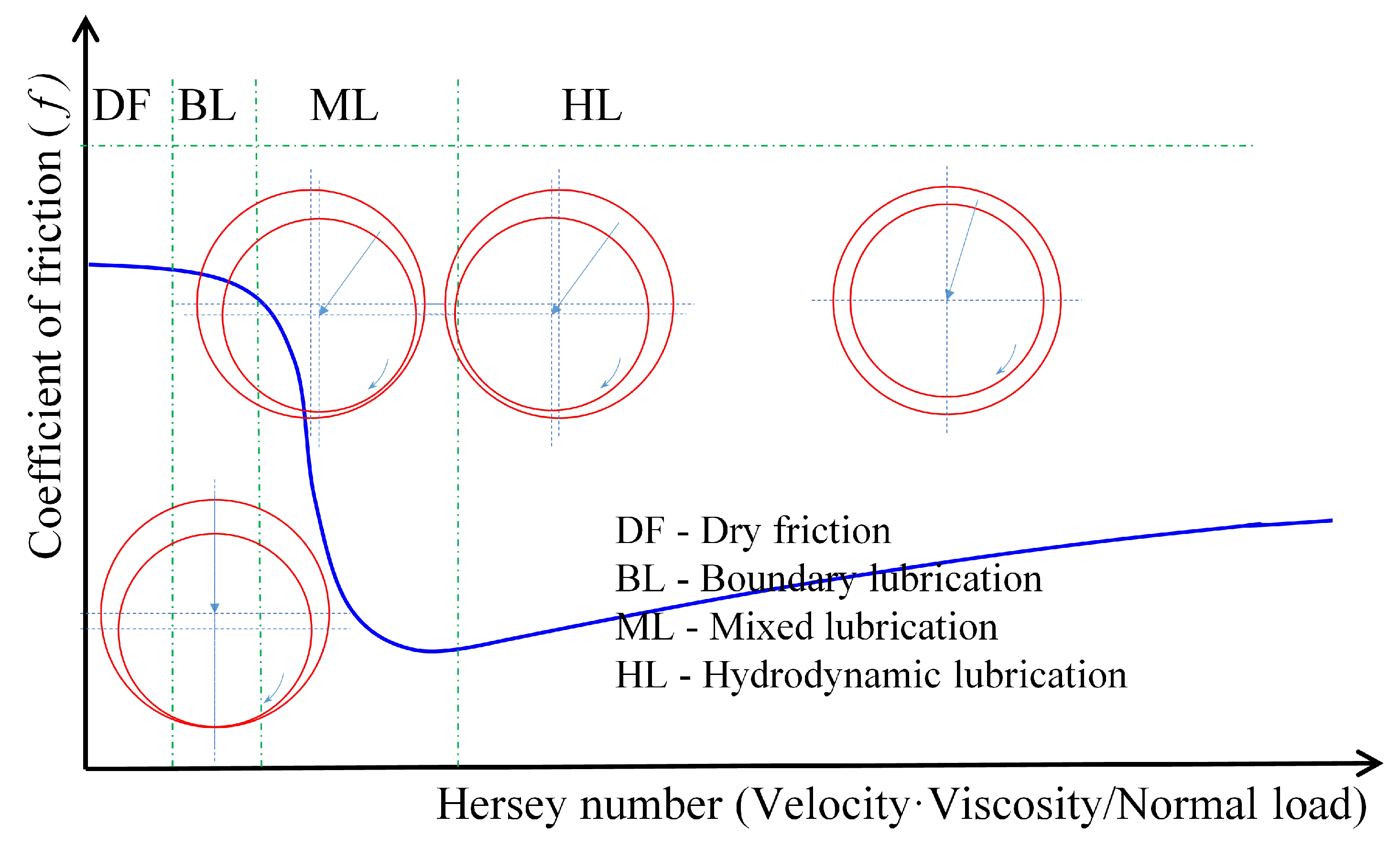
3.2.1. Lubrication State Control
3.2.2. Temperature Rise Control
3.3. Selection of Controllable Parameters and Experimental Design
3.4. Experimental Rig and Bearing
3.5. Experimental Plan
4. Results and Discussion
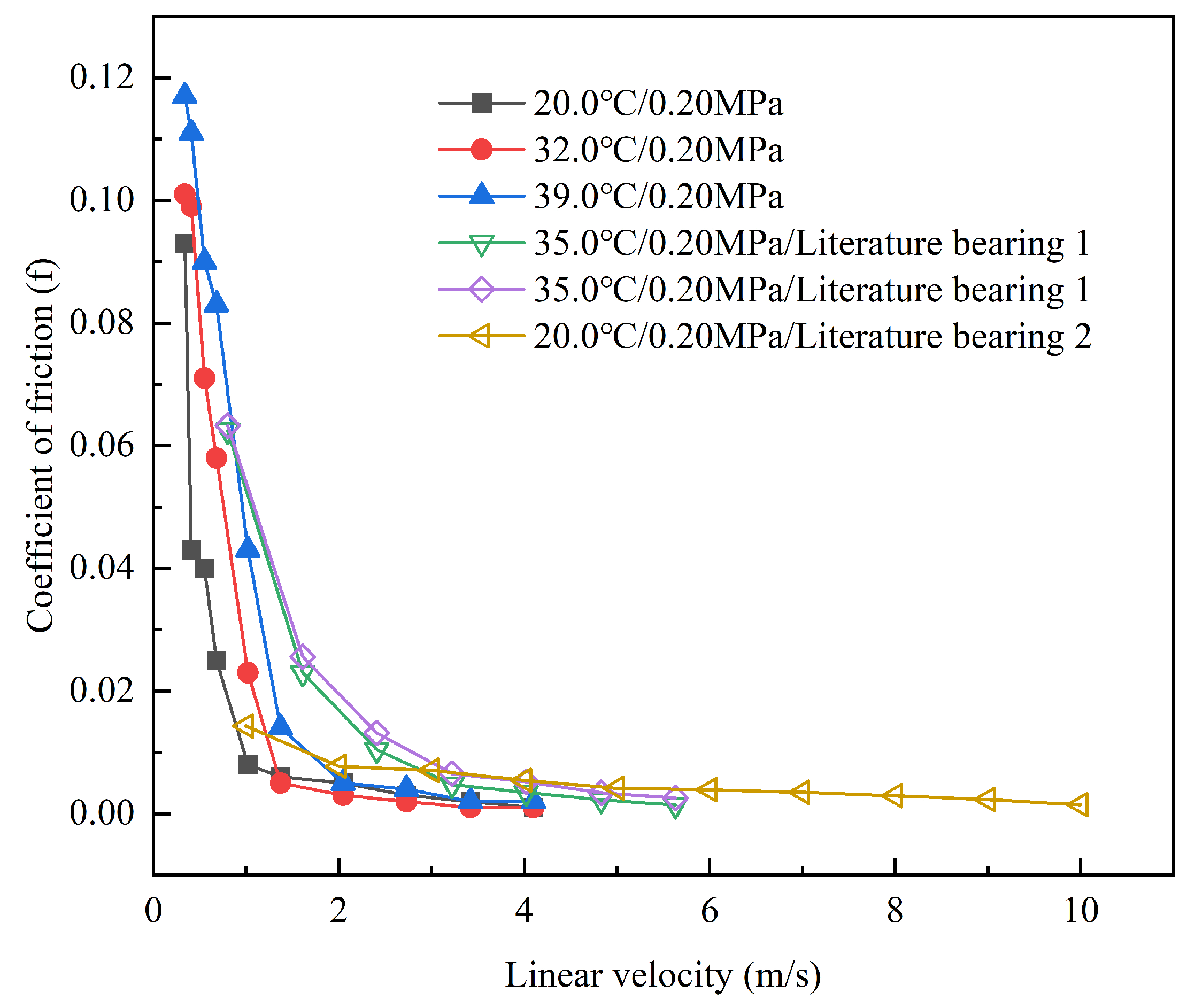
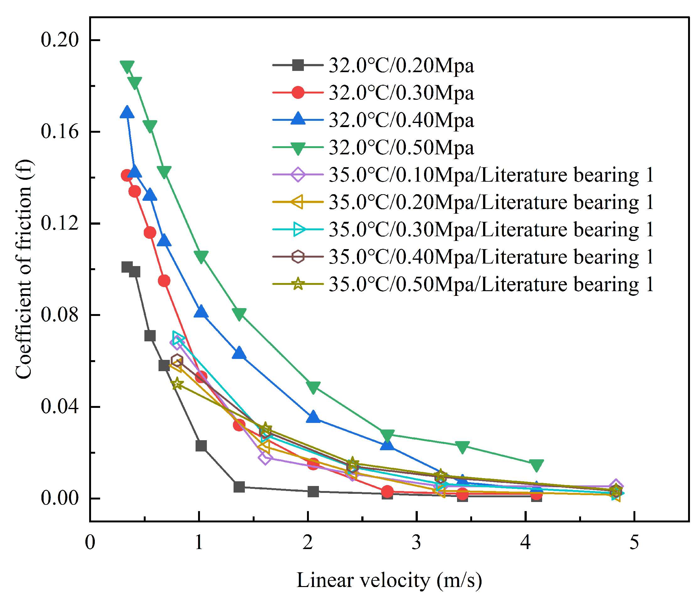
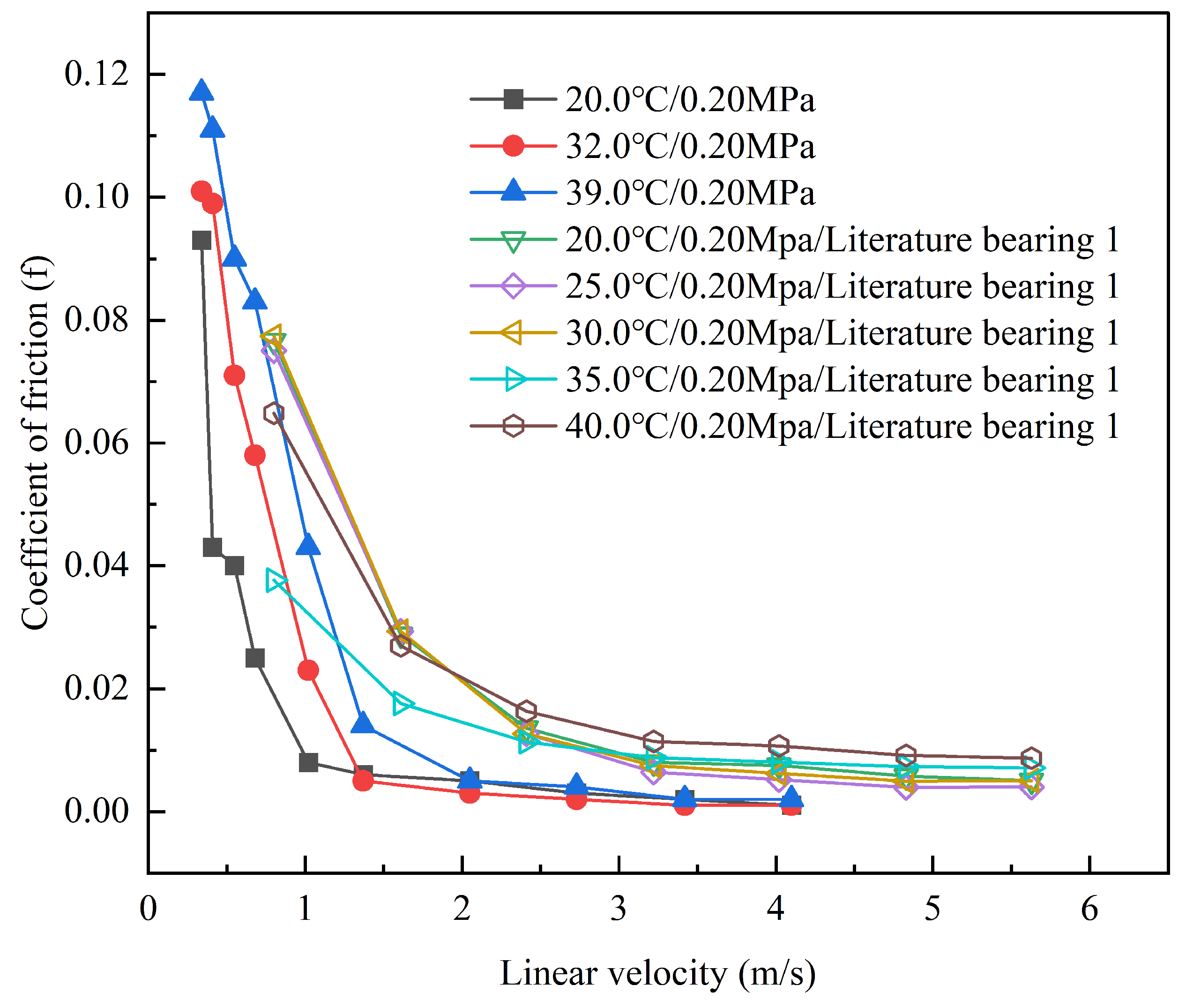
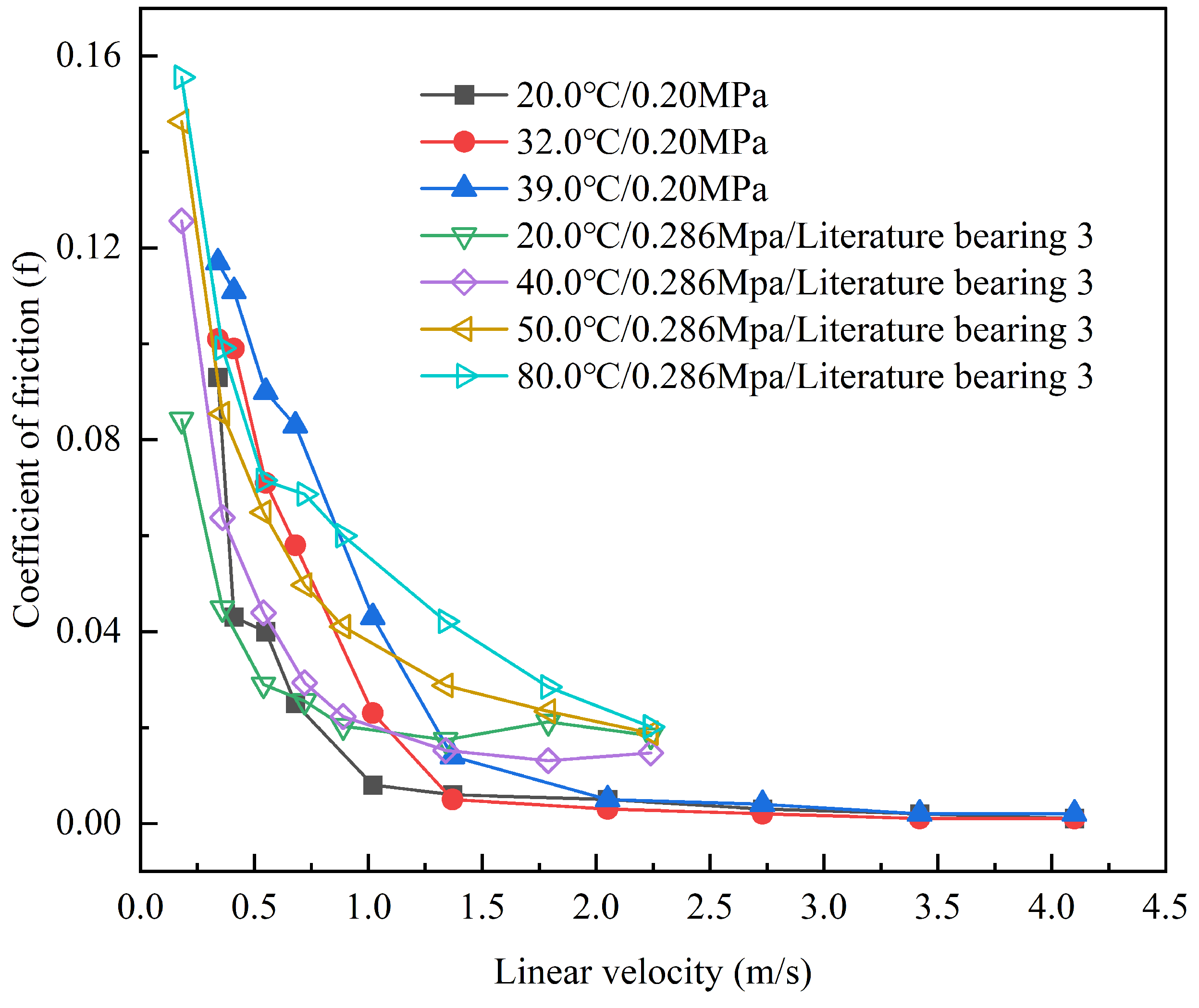
4.1. Experimental Results Compared with Published Literature
4.2. Influence of Surface Morphology on Speed Characteristics
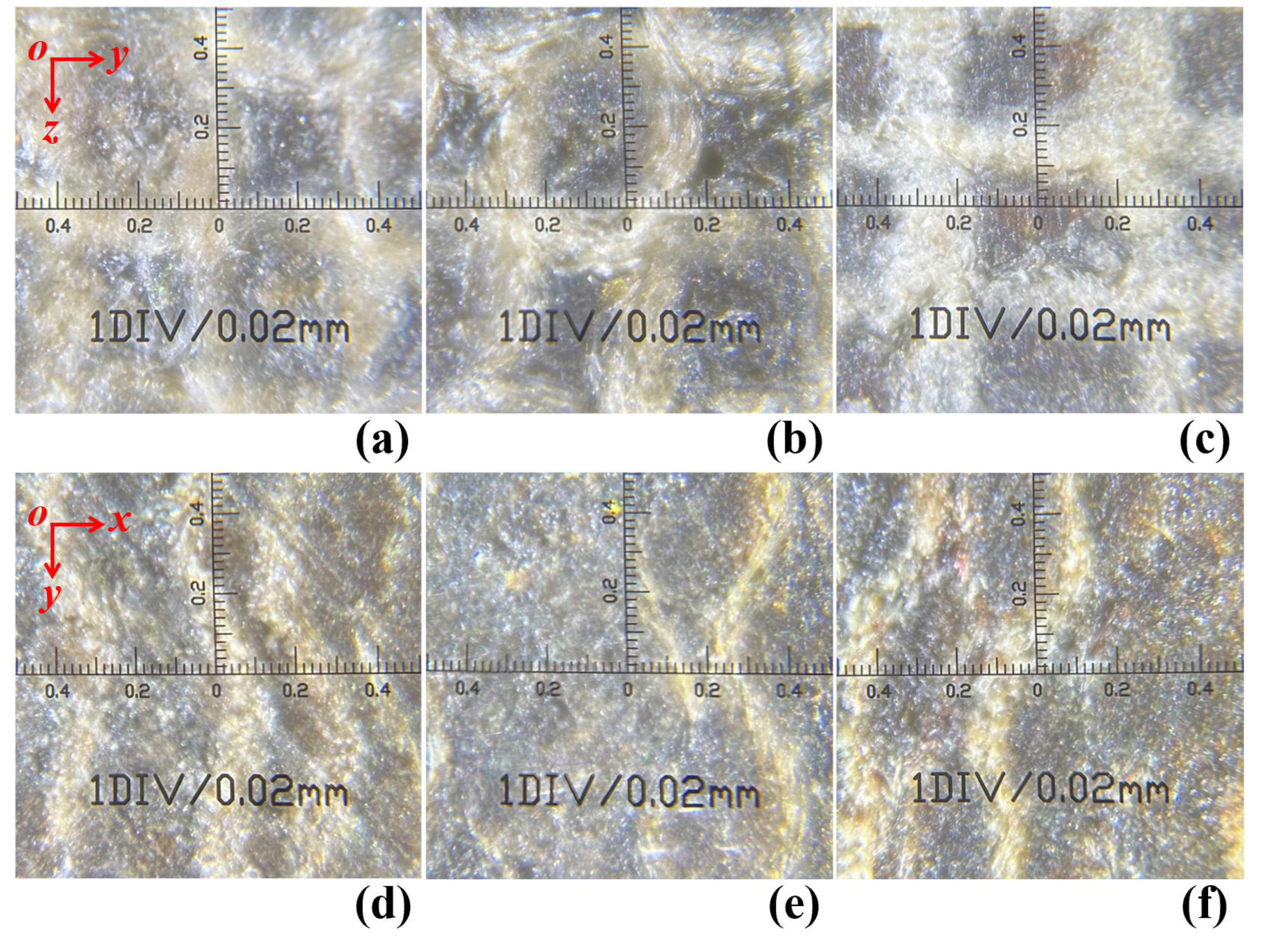
4.2.1. Changes in Surface Morphology of Strips Due to Water Swelling and Break-In Treatments
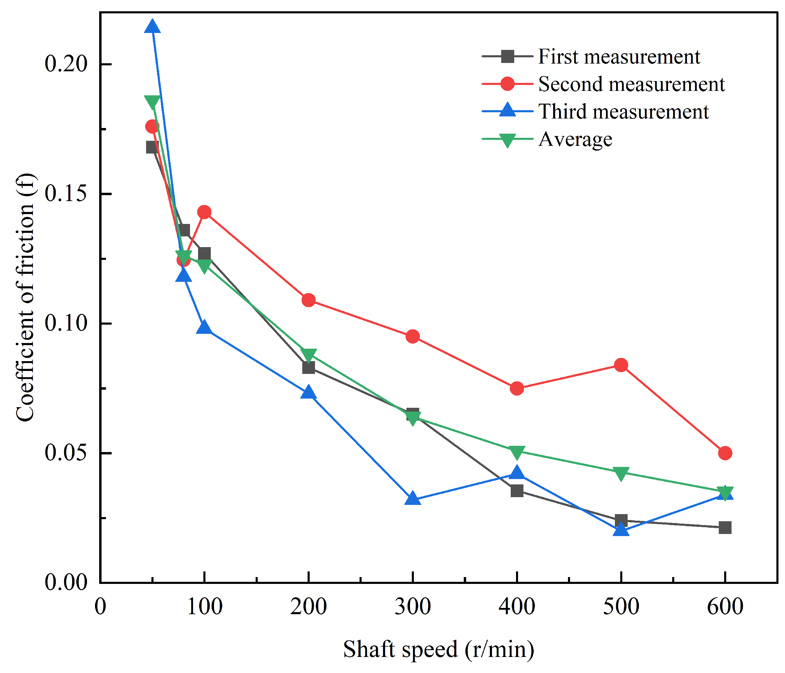
4.2.2. Velocity Characteristics of Rough Surface States
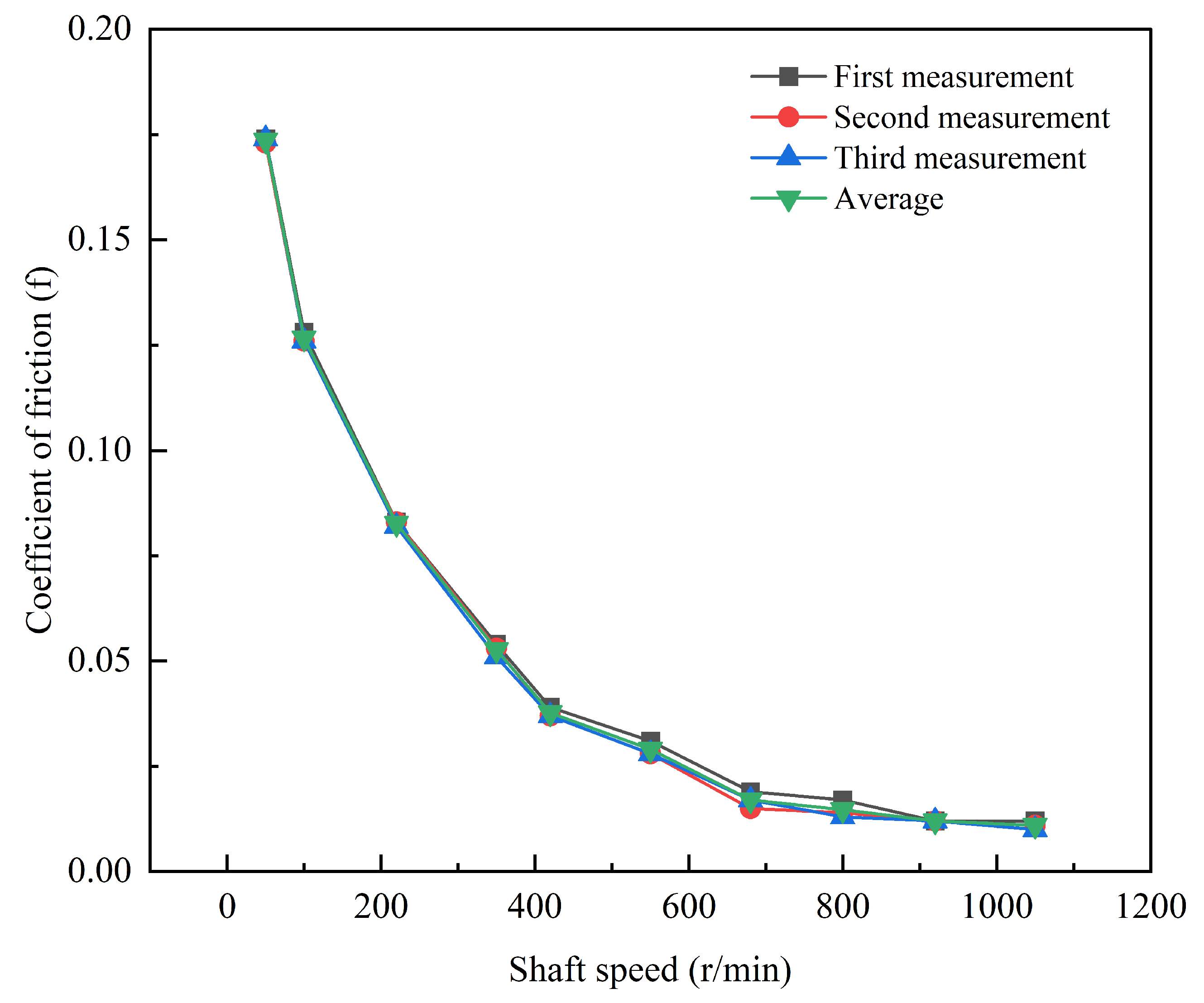
4.2.3. Velocity Characteristics of Smooth Surface States
4.2.4. Impact of Surface Morphology Changes on Lubrication Characteristics and Temperature Rise
4.3. Influence of Controllable Parameters on Lubrication Characteristics
4.3.1. Influence of Lubricant Water Temperature at the Bearing Inlet on Lubrication Characteristics
4.3.2. Influence of Shaft Speed on Lubrication Characteristics
4.3.3. Influence of Bearing Specific Pressure on Lubrication Characteristics
4.3.4. Influence of Lubricating Water Containing Sediments on Lubrication Characteristics
4.4. Influence of Controllable Parameters on Temperature Rise Characteristics
4.4.1. Influence of Lubricant Water Temperature at the Bearing Inlet on Temperature Rise Characteristics
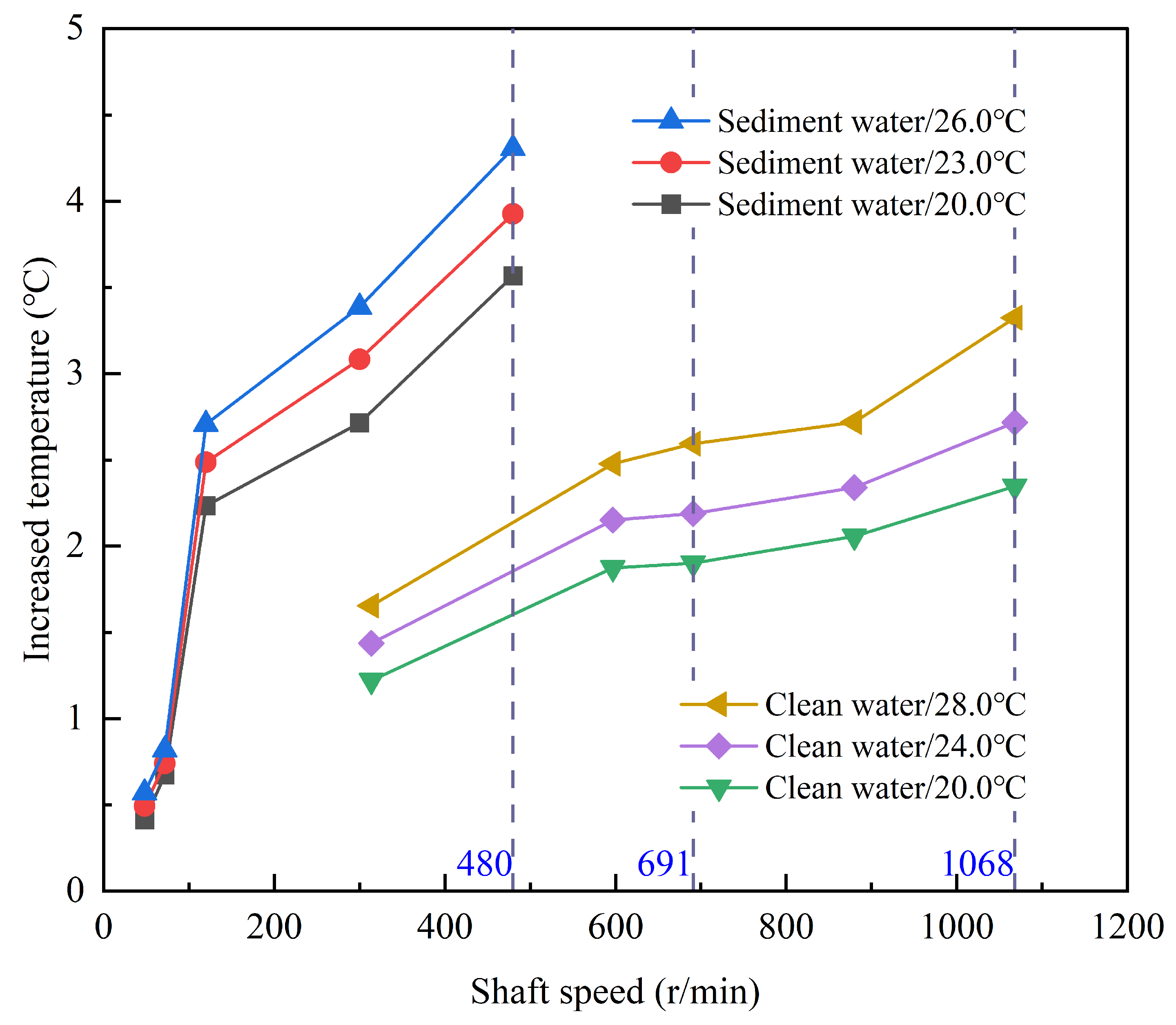
4.4.2. Influence of Bearing Speed on Temperature Rise Characteristics
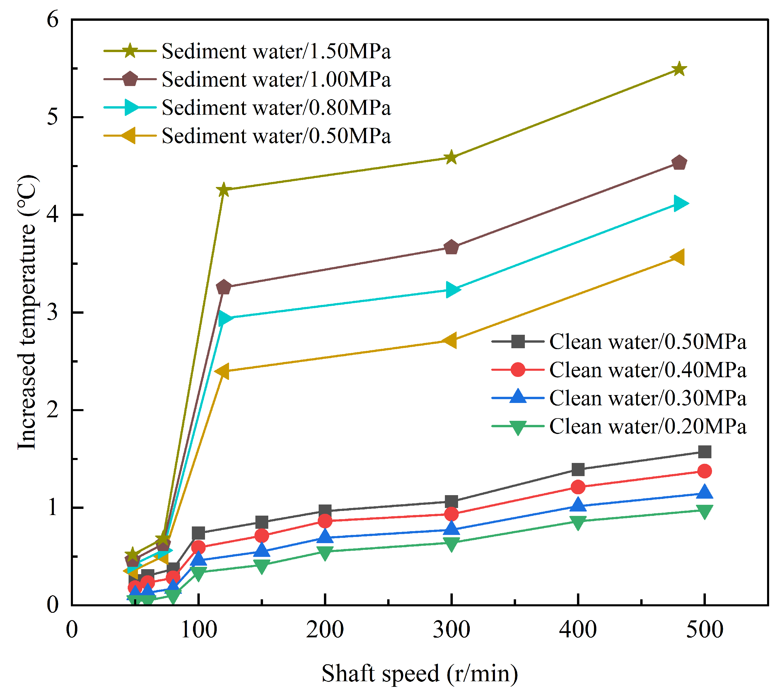
4.4.3. Influence of Bearing Specific Pressure on Temperature Rise Characteristics
4.4.4. Influence of Sediment in Lubricating Water on Temperature Rise Characteristics
4.5. The Impact of Lubrication and Temperature Rise on Service Performance and Surface Morphology
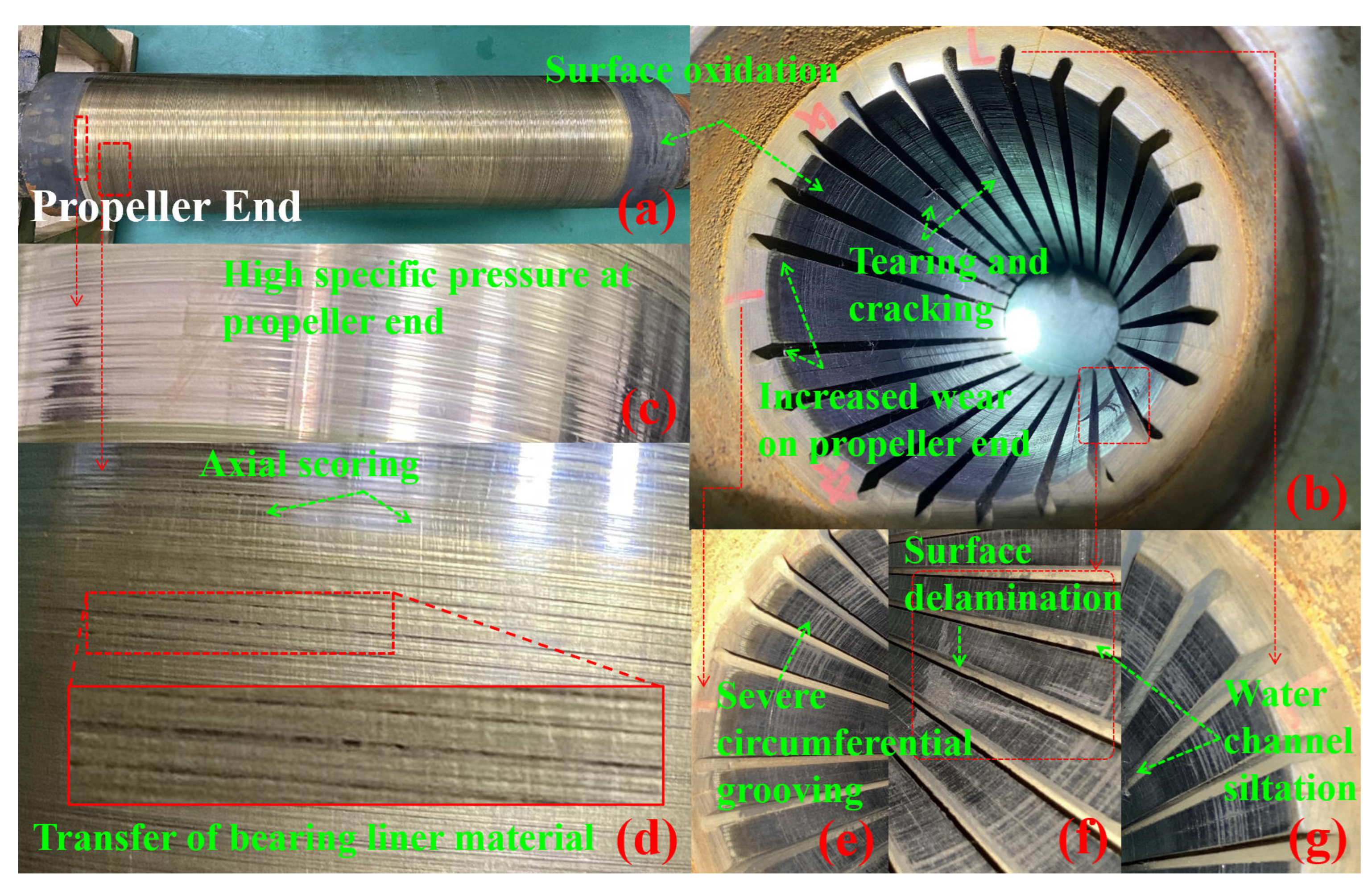
4.5.1. The Effects of Abnormal Lubrication and Temperature Rise on Bearing Wear Characteristics and Surface Morphology
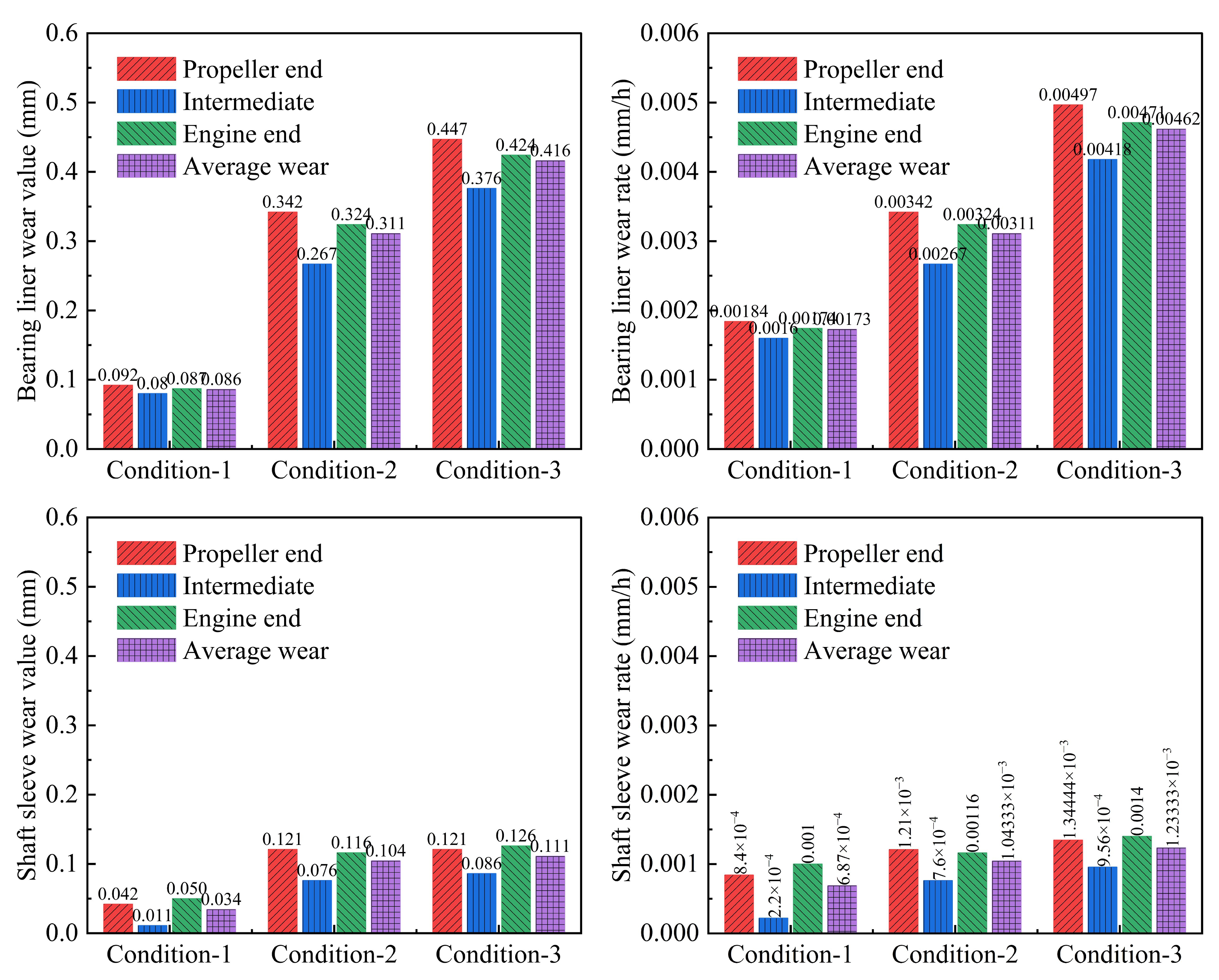
4.5.2. Analysis of Wear Value and Wear Rate of Bearing Liner and Shaft Sleeve
4.6. Statistical Analysis of Stern Bearing Operational State Monitoring Parameters
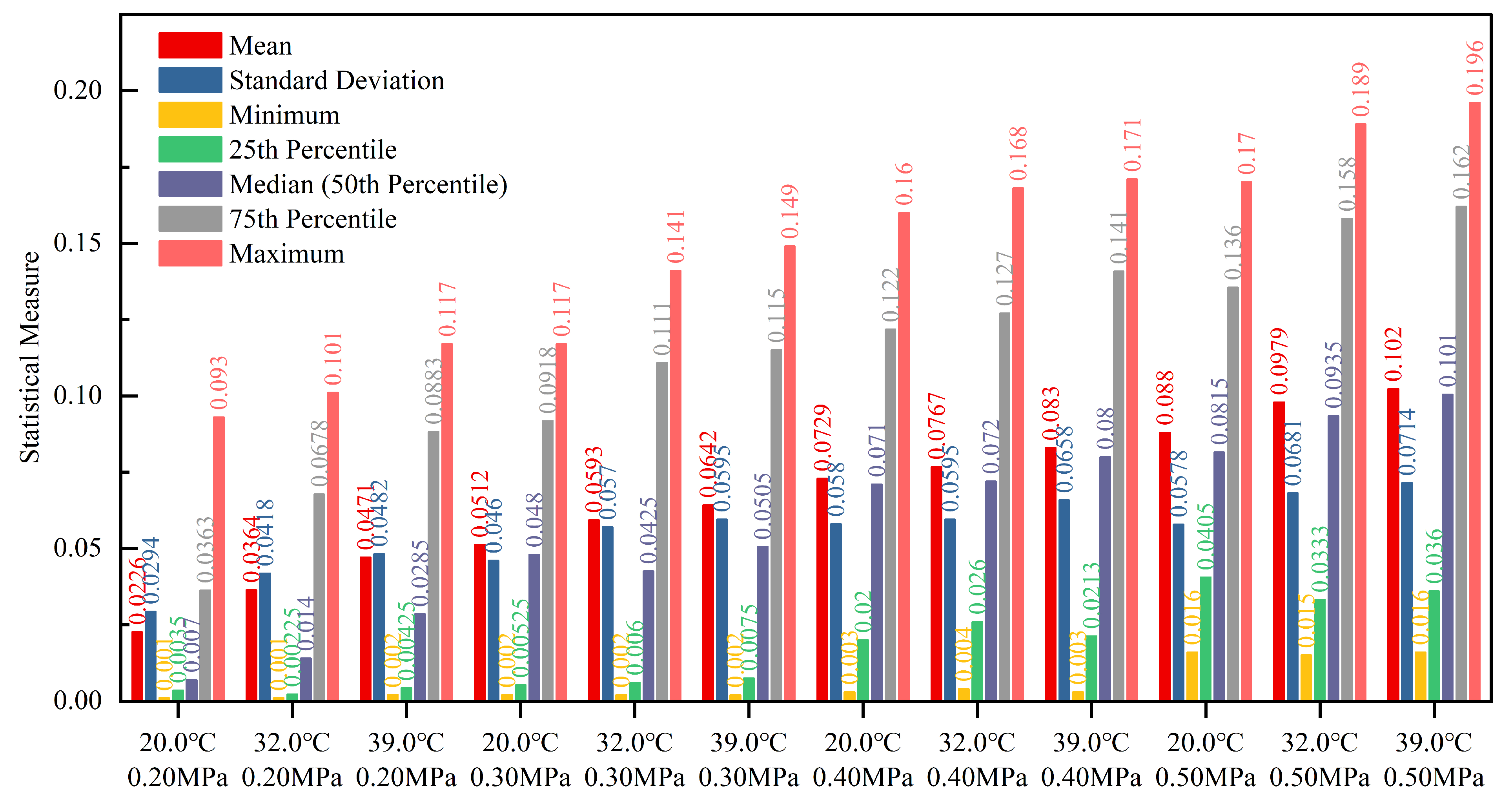
4.6.1. Basic Statistical Analysis
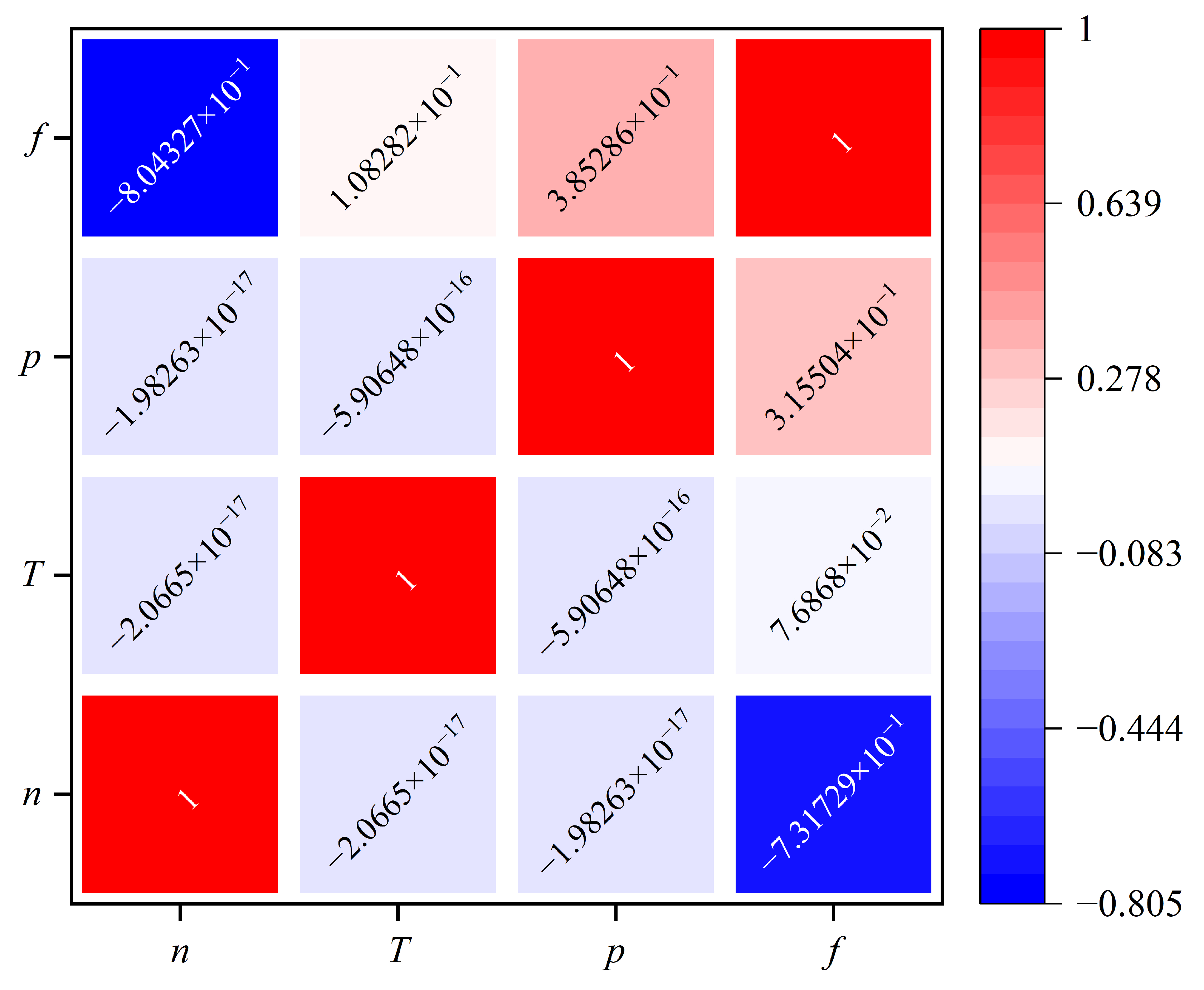
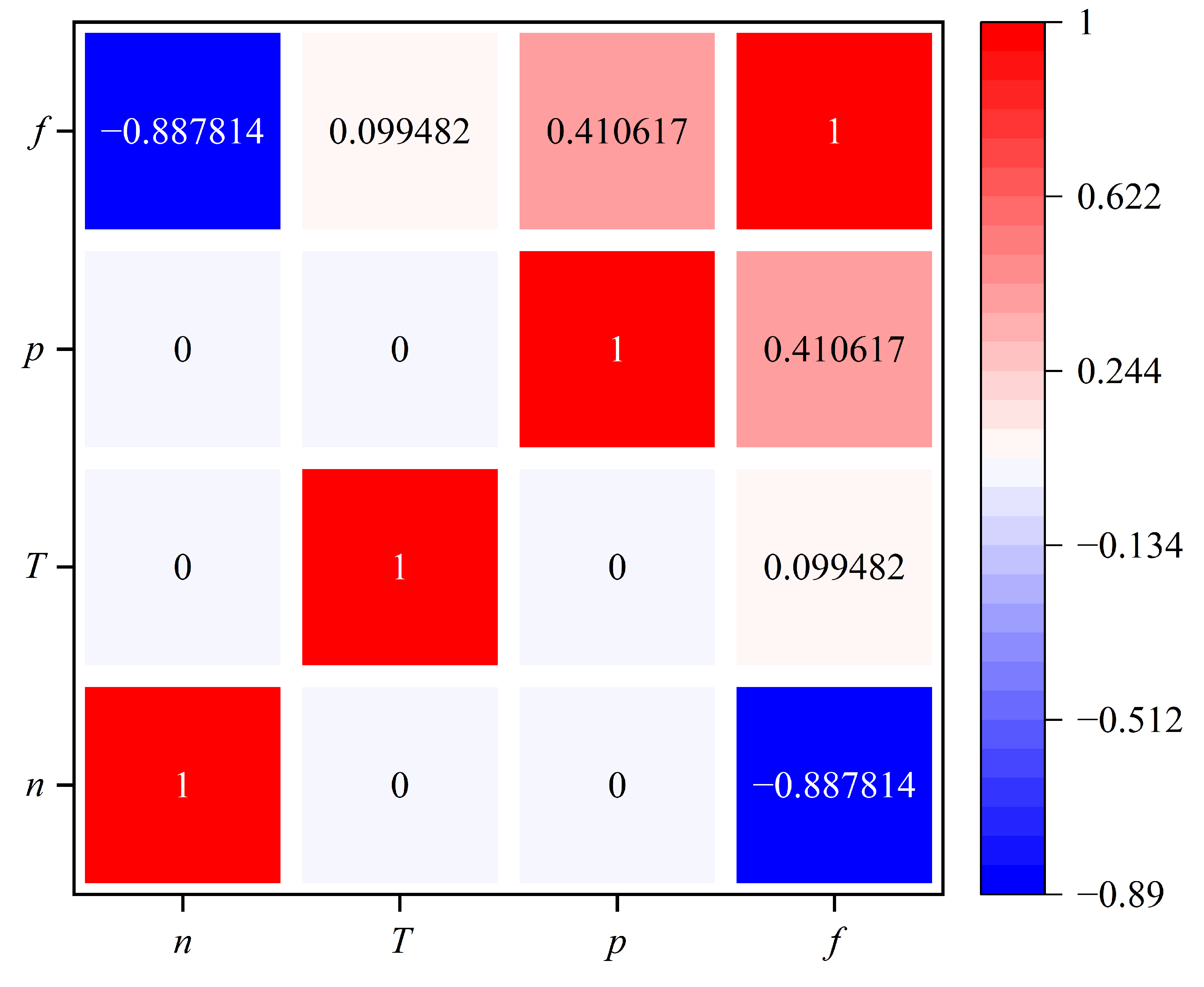
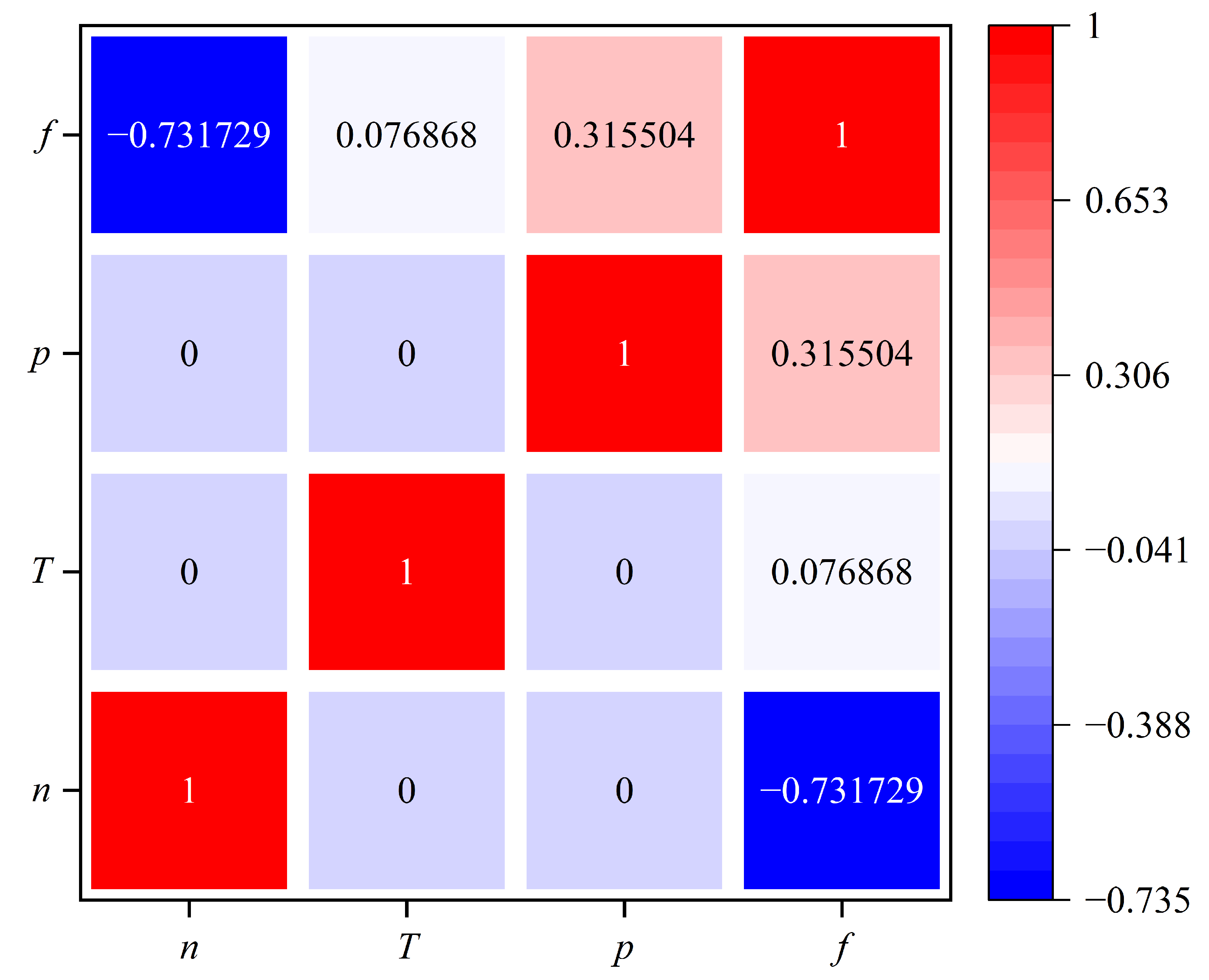
4.6.2. Correlation Analysis of n/T/p/f
4.6.3. Sensitivity Analysis of Controllable Parameters in Friction and Wear Behavior
4.6.4. Sensitivity Analysis of Controllable Parameters in Temperature Rise Behavior
5. Conclusions
Author Contributions
Funding
Institutional Review Board Statement
Informed Consent Statement
Data Availability Statement
Conflicts of Interest
References
- Morad, O.; Viitala, R.; Saikko, V. Behavior of marine thruster lip seals under typical operating conditions. Tribol. Int. 2025, 201, 110195. [Google Scholar] [CrossRef]
- Yang, K.; Zhang, T. Lubrication analysis of stern bearing during ship severe turning maneuver. Wear 2023, 523, 204734. [Google Scholar] [CrossRef]
- Lu, G.; Zou, Y.; Chen, X.; Shi, R.; Wang, G.; Zhu, L.; Xie, X.; Sun, W.; Yang, J.; Chang, S.; et al. Micro-morphological analysis, lubricating behaviors, and wear failure characteristics and mechanisms of propeller hub bearings in marine environments. Wear 2023, 530–531, 205047. [Google Scholar] [CrossRef]
- Chen, S.; Xiang, G.; Fillon, M.; Guo, J.; Wang, J.; Cai, J. On the tribo-dynamic behaviors during start-up of water lubricated bearing considering imperfect journal. Tribol. Int. 2022, 174, 107685. [Google Scholar] [CrossRef]
- Zhang, Z.; Ouyang, W.; Liang, X.; Yan, X.; Yuan, C.; Zhou, X.; Guo, Z.; Dong, C.; Liu, Z.; Jin, Y.; et al. Review of the evolution and prevention of friction, wear, and noise for water-lubricated bearings used in ships. Friction 2024, 12, 1–38. [Google Scholar] [CrossRef]
- Magalhães, D.L.; Martins, D.H.C.d.S.S.; Castro, B.M.; Vaz, L.A.; Monteiro, U.A.; Gutiérrez, R.H.R. Machine learning performance comparison for main propulsive shafting systems alignment. Ocean Eng. 2023, 280, 114556. [Google Scholar] [CrossRef]
- Hongling, Q.; Chang, Y.; Hefa, Z.; Xufei, L.; Zhixiong, L.; Xiang, X. Experimental analysis on friction-induced vibration of water-lubricated bearings in a submarine propulsion system. Ocean Eng. 2020, 203, 107239. [Google Scholar] [CrossRef]
- Jin, Y.; Li, R.; Ouyang, W.; Liu, Z.; Liu, Q.; Xiong, Q.; Zhou, J. Feature Recognition on Friction Induced Vibration of Water-Lubricated Bearing under Low Speed and Heavy Load. J. Mar. Sci. Eng. 2023, 11, 465. [Google Scholar] [CrossRef]
- Litwin, W.; Kropp, S. Sliding bearings with sintered bronze bush lubricated by contaminated water with solid particles – Theoretical and experimental studies. Wear 2023, 532–533, 205070. [Google Scholar] [CrossRef]
- Wu, Z.; Yuan, C.; Guo, Z.; Huang, Q. Effect of the groove parameters on the lubricating performance of the water-lubricated bearing under low speed. Wear 2023, 522, 204708. [Google Scholar] [CrossRef]
- Xie, Z.; Li, J.; Tian, Y.; Du, P.; Zhao, B.; Xu, F. Theoretical and experimental study on influences of surface texture on lubrication performance of a novel bearing. Tribol. Int. 2024, 193, 109351. [Google Scholar] [CrossRef]
- Farfan-Cabrera, L.I.; Pérez-González, J.; Iniestra-Galindo, M.G.; Marín-Santibáñez, B.M. Production and tribological evaluation of polypropylene nanocomposites with reduced graphene oxide (rGO) for using in water-lubricated bearings. Wear 2021, 477, 203860. [Google Scholar] [CrossRef]
- Maslavi, A.; Unal, H.; Olabi, M.N. Determination of “tribological performance working fields” for pure PEEK and PEEK composites under dry sliding conditions. Wear 2024, 554–555, 205464. [Google Scholar] [CrossRef]
- Li, S.; Dong, C.; Yuan, C.; Bai, X. Effects of TiO2 nano-particles on wear-resistance and vibration-reduction properties of a polymer for water-lubricated bearing. Wear 2023, 522, 204713. [Google Scholar] [CrossRef]
- Chen, J.; Liang, X.; Guo, Z.; Li, X.; Yuan, C. Insight into the wear properties of fiber fabric surface-enhanced composite under water lubrication. Tribol. Int. 2023, 187, 108714. [Google Scholar] [CrossRef]
- Wang, H.; Liu, Z.; Zou, L.; Yang, J. Influence of both friction and wear on the vibration of marine water lubricated rubber bearing. Wear 2017, 376, 920–930. [Google Scholar] [CrossRef]
- BahooToroody, A.; Abaei, M.M.; Banda, O.V.; Kujala, P.; De Carlo, F.; Abbassi, R. Prognostic health management of repairable ship systems through different autonomy degree; From current condition to fully autonomous ship. Reliab. Eng. Syst. Saf. 2022, 221, 108355. [Google Scholar] [CrossRef]
- Xu, X.; Yan, X.; Yang, K.; Zhao, J.; Sheng, C.; Yuan, C. Review of condition monitoring and fault diagnosis for marine power systems. Transp. Saf. Environ. 2021, 3, 85–102. [Google Scholar] [CrossRef]
- Chang, X.; Xu, X.; Qiu, B.; Wei, M.; Yan, X.; Liu, J. Predicting steady degradation in ship power system: A deep learning approach based on comprehensive monitoring parameters. IET Intell. Transp. Syst. 2024, 18, 2375–2396. [Google Scholar] [CrossRef]
- Mosayebi Omshi, E.; Shemehsavar, S.; Grall, A. An intelligent maintenance policy for a latent degradation system. Reliab. Eng. Syst. Saf. 2024, 242, 109739. [Google Scholar] [CrossRef]
- Hendradewa, A.P.; Yin, S. Comparative analysis of offshore wind turbine blade maintenance: RL-based and classical strategies for sustainable approach. Reliab. Eng. Syst. Saf. 2025, 253, 110477. [Google Scholar] [CrossRef]
- Chang, X.; Yan, X.; Qiu, B.; Wei, M.; Liu, J.; Zhu, H. Anomaly detection and confidence interval-based replacement in decay state coefficient of ship power system. IET Intell. Transp. Syst. 2024, 18, 2409–2439. [Google Scholar] [CrossRef]
- Lv, X.; Shi, L.; He, Y.; He, Z. Joint optimization of production, inspection, and maintenance under finite time for smart manufacturing systems. Reliab. Eng. Syst. Saf. 2025, 253, 110490. [Google Scholar] [CrossRef]
- Zhang, H.; Yuan, C.; Tan, Z. A novel approach to investigate temperature field evolution of water lubricated stern bearings (WLSBs) under hydrodynamic lubrication. Adv. Mech. Eng. 2021, 13, 1687814021992961. [Google Scholar] [CrossRef]
- Chen, R.; Zhao, B.; Xin, Q.; Niu, X.; Xie, Z.; Lu, X.; Zou, D. Analysis of transient lubrication and wear coupling behaviors considering thermal effect and journal misalignment for main bearings under dynamic load. Wear 2024, 554–555, 205478. [Google Scholar] [CrossRef]
- Qin, S.; Guo, Z.; Wu, Z.; Yuan, C. Insights of particle types on interface wear properties of different water-lubricated bearing materials. Tribol. Int. 2024, 200, 110140. [Google Scholar] [CrossRef]
- Huang, J.; Zhou, X.; Wang, J.; Tang, X.; Kuang, F. Influence of temperature on friction of polymeric materials in water. Wear 2019, 426–427, 868–876. [Google Scholar] [CrossRef]
- Chen, S.; Cai, J.; Xiang, G.; Zhang, J.; Liu, Z.; Fillon, M. Tribo-Dynamic-Wear coupling analysis for Water-lubricated Bearings with journal surface imperfection under repeated start-stop cycles. Tribol. Int. 2024, 200, 110093. [Google Scholar] [CrossRef]
- Jing, H.; Li, K.; Chen, L.; Yang, Q. Analysis and Repair of Bearing Abrasion for Large Semi-Submersible Vessels. Ship Eng. 2023, 45, 135–141. [Google Scholar] [CrossRef]
- Huang, L. Causes of Damage and Repairs to Water-lubricated Stern Bearings. China Ship Survey 2004, 08, 83. [Google Scholar]
- Xie, R. Analysis of Excessive Wear in Water-lubricated Stern Bearings Under Special Operating Conditions. In Outstanding Maritime Science and Technology Papers; Jiangsu Maritime Institute: Nanjing, China, 2014; p. 6. [Google Scholar]
- Wei, H.; Bai, D. Analysis and repair of overworn stern bearing. Mech. Electr. Equip. 2000, 3, 22–23. [Google Scholar]
- Xie, Z. Analysis of Wear Defects in Seawater Lubricated Stern Bearings and Key Points of Engine Room Management. China Shiprep. 2012, 25, 59–60. [Google Scholar]
- Lin, Z. Diagnostic and Repair of Alignment Failure in a Ship’s Stern Shaft System. China Shiprep. 2013, 26, 10–13. [Google Scholar]
- Tang, J.; Huang, X.; Han, Y.; Lu, L. Analysis of After Stern Tube Bearing Abrasion under Rough Sea Condition. Ship Eng. 2017, 39, 98–100+146. [Google Scholar] [CrossRef]
- Zhang, F.; He, T.; Jiang, W. Analysis of Wear Mechanisms in Water-lubricated Stern Tube Bearings and Structural Design. China Shiprep. 2021, 34, 1–3. [Google Scholar] [CrossRef]
- Lin, C.G.; Yang, Y.N.; Chu, J.L.; Sima, C.; Liu, P.; Qi, L.B.; Zou, M.S. Study on nonlinear dynamic characteristics of propulsion shafting under friction contact of stern bearings. Tribol. Int. 2023, 183, 108391. [Google Scholar] [CrossRef]
- Zu, E. A Solution for Wear Fault of Stern Tube Closed Water Lubricated Bearing. Mech. Electr. Equip. 2023, 40, 47–50. [Google Scholar] [CrossRef]
- Deng, Y.; Li, Y.; Zhu, H.; Fan, S. Displacement Values Calculation Method for Ship Multi-Support Shafting Based on Transfer Learning. J. Mar. Sci. Eng. 2024, 12, 36. [Google Scholar] [CrossRef]
- Litwin, W. Water-lubricated bearings of ship propeller shafts-problems, experimental tests and theoretical investigations. Pol. Marit. Res. 2009, 16, 41–49. [Google Scholar] [CrossRef]
- ung Lee, J.; Jeong, B.; An, T.H. Investigation on effective support point of single stern tube bearing for marine propulsion shaft alignment. Mar. Struct. 2019, 64, 1–17. [Google Scholar] [CrossRef]
- Ortolani, F.; Dubbioso, G.; Muscari, R.; Mauro, S.; Di Mascio, A. Experimental and Numerical Investigation of Propeller Loads in Off-Design Conditions. J. Mar. Sci. Eng. 2018, 6, 45. [Google Scholar] [CrossRef]
- Gaggero, S.; Dubbioso, G.; Villa, D.; Muscari, R.; Viviani, M. Propeller modeling approaches for off–design operative conditions. Ocean Eng. 2019, 178, 283–305. [Google Scholar] [CrossRef]
- Zhao, X.; Wang, L.; Zhao, G. Analysis of Scorching Reasons for Certain Ship Stern Tube Bearings and Repair Measures. China Shiprep. 2017, 30, 17–19. [Google Scholar] [CrossRef]
- Litwin, W.; Dymarski, C. Experimental research on water-lubricated marine stern tube bearings in conditions of improper lubrication and cooling causing rapid bush wear. Tribol. Int. 2016, 95, 449–455. [Google Scholar] [CrossRef]
- Hua, Y. Design of a Flow Interruption Alarm Device for Forced Cooling Water in Tailshaft Polymer Water-lubricated Bearings. China Water Transp. 2010, 10, 128–129. [Google Scholar]
- Ao, W. Troubleshooting and Analysis of High Temperature Issues in Ship Stern Bearings. Mar. Equip./Mater. Mark. 2019, 8, 37–40. [Google Scholar] [CrossRef]
- Zhao, G.; Zhang, J.; Guo, Z.; Zhong, W.; Zuo, D. Key Points and Improvement Measures for the Management of Ship Stern Tube Water-lubrication Devices. Marit. Saf. 2023, 2, 171–174. [Google Scholar]
- Bhushan, B. Stick-Slip Induced Noise Generation in Water-Lubricated Compliant Rubber Bearings. J. Lubr. Technol. 1980, 102, 201–210. [Google Scholar] [CrossRef]
- Simpson, T.; Ibrahim, R. Nonlinear Friction-Induced Vibration in Water-Lubricated Bearings. J. Vib. Control 1996, 2, 87–113. [Google Scholar] [CrossRef]
- Peng, E.; lin Liu, Z.; Zhou, X.; Zhao, M.; Lan, F. Application of Vibration and Noise Analysis in Water-Lubricated Rubber Bearings Fault Diagnosis. Adv. Mater. Res. 2011, 328–330, 1995–1999. [Google Scholar] [CrossRef]
- Peng, E.G.; Zheng, L.L.; Tian, Y.Z.; Lan, F. Experimental study on friction-induced vibration of water-lubricated rubber stern bearing at low speed. Appl. Mech. Mater. 2011, 44, 409–413. [Google Scholar] [CrossRef]
- Peng, E.G.; Liu, Z.L.; Lan, F.; Zhang, S.D.; Dai, M.C. Research on noise generation mechanism of rubber material for water-lubricated bearings. Appl. Mech. Mater. 2011, 84, 539–543. [Google Scholar] [CrossRef]
- Cheng, Y.C.; Liu, Z.L.; Wang, J.; Dai, Y.; Peng, E.G. Experimental study on temperature characteristics of water lubricated rubber bearing. Adv. Mater. Res. 2012, 479, 1097–1101. [Google Scholar] [CrossRef]
- Peng, E.; Liu, Z.; Zhou, X.; Tian, Y.; Zhao, M. Study on nonlinear friction-induced vibration in water-lubricated rubber stern tube bearings. Open Mech. Eng. J. 2012, 6, 140–147. [Google Scholar] [CrossRef]
- Ouyang, W.; Zhang, X.; Jin, Y.; Yuan, X. Experimental study on the dynamic performance of water-lubricated rubber bearings with local contact. Shock Vib. 2018, 2018, 6309727. [Google Scholar] [CrossRef]
- Jin, Y.; Liu, Z.; Zhou, X. Theoretical, numerical, and experimental studies on friction vibration of marine water-lubricated bearing coupled with lateral vibration. J. Mar. Sci. Technol. 2020, 25, 298–311. [Google Scholar] [CrossRef]
- Jin, Y.; Lu, J.; Ouyang, W.; Liu, Z.; Lao, K. Vibration reduction performance of damping-enhanced water-lubricated bearing using fluid-saturated perforated slabs. Chin. J. Mech. Eng. 2020, 33, 92. [Google Scholar] [CrossRef]
- Li, Y.; Hua, K.; Tong, Y. Analysis of a Case of Stern Shaft Fracture on a Coastal Bulk Cargo Ship. Mar. Technol. 2022, 3, 37–40. [Google Scholar]
- Du, F.; Li, D.; Sa, X.; Li, C.; Yu, Y.; Li, C.; Wang, J.; Wang, W. Overview of friction and wear performance of sliding bearings. Coatings 2022, 12, 1303. [Google Scholar] [CrossRef]
- Xiang, G.; Han, Y.; He, T.; Wang, J.; Xiao, K.; Li, J. Wear and fluid-solid-thermal transient coupled model for journal bearings. Appl. Math. Model. 2020, 85, 19–45. [Google Scholar] [CrossRef]
- Guo, J.; Zheng, W.; Han, Y.; Zhu, L.; Che, Y.; Wang, J.; Wang, M. Diagnostic method and application of low speed sliding bearing wear fault. In Proceedings of the IOP Conference Series: Materials Science and Engineering, Sanya, China, 9–10 November 2019; IOP Publishing: Bristol, UK, 2020; Volume 772, p. 012028. [Google Scholar] [CrossRef]
- Li, H.; Yin, Z.; Wang, Y. A study on the wear behavior of tin-based journal bearing under different working conditions. Ind. Lubr. Tribol. 2020, 72, 359–368. [Google Scholar] [CrossRef]
- Tong, D.; Diao, Z.; Sun, N.; Du, X.; Zhang, Y.; Liu, Z. A review of dynamic-tribological simulation methods for sliding bearings in internal combustion engines. In Proceedings of the Journal of Physics: Conference Series, Beijing, China, 19–20 November 2021; IOP Publishing: Bristol, UK, 2021; Volume 2101, p. 012014. [Google Scholar] [CrossRef]
- Jin, Y.F. Simulation Research on Dynamic Tribological Systems of Plain Bearing. Adv. Mater. Res. 2012, 426, 297–302. [Google Scholar] [CrossRef]
- Yang, X.; Gu, G.; Sun, S.; Li, S.; Zhou, J. Analysis and Experimental Validation of the Tribological and Dynamic Characteristics of Journal Bearings. In Proceedings of the E3S Web of Conferences, Rome, Italy, 22–23 September 2021; EDP Sciences: Les Ulis, France, 2021; Volume 313, p. 02001. [Google Scholar] [CrossRef]
- Zhang, S.; Deguo, W.; Weihua, Y. Investigation of abrasive erosion of polymers. J. Mater. Sci. 1995, 30, 4561–4566. [Google Scholar] [CrossRef]
- Dong, C.; Yuan, C.; Bai, X.; Yan, X.; Peng, Z. Study on wear behaviour and wear model of nitrile butadiene rubber under water lubricated conditions. Rsc Adv. 2014, 4, 19034–19042. [Google Scholar] [CrossRef]
- Dong, C.; Yuan, C.; Liu, Z.; Yan, X. Study on Evaluation Model of Wear Reliability Life of Water Lubricated Stern Tube Bearing. Lubr. Eng. 2010, 35, 40–43. [Google Scholar]
- Zou, Z.; Dong, C.; Yuan, C.; Mao, S.; Yan, X. Analysis reliability life of water lubricated rubber stern tube bearing based on two-parameter weibull distribution. Ship Sci. Technol. 2015, 37, 48–52. [Google Scholar]
- Lei, Y.; Li, N.; Guo, L.; Li, N.; Yan, T.; Lin, J. Machinery health prognostics: A systematic review from data acquisition to RUL prediction. Mech. Syst. Signal Process. 2018, 104, 799–834. [Google Scholar] [CrossRef]
- Alsuwian, T.; Ansari, S.; Ammirrul Atiqi Mohd Zainuri, M.; Ayob, A.; Hussain, A.; Hossain Lipu, M.; Alhawari, A.R.; Almawgani, A.; Almasabi, S.; Taher Hindi, A. A review of expert hybrid and co-estimation techniques for SOH and RUL estimation in battery management system with electric vehicle application. Expert Syst. Appl. 2024, 246, 123123. [Google Scholar] [CrossRef]
- König, F.; Wirsing, F.; Singh, A.; Jacobs, G. Machine-Learning-Based Wear Prediction in Journal Bearings under Start–Stop Conditions. Lubricants 2024, 12, 290. [Google Scholar] [CrossRef]
- Velasco-Gallego, C.; Navas De Maya, B.; Matutano Molina, C.; Lazakis, I.; Cubo Mateo, N. Recent advancements in data-driven methodologies for the fault diagnosis and prognosis of marine systems: A systematic review. Ocean Eng. 2023, 284, 115277. [Google Scholar] [CrossRef]
- Moder, J.; Bergmann, P.; Grün, F. Lubrication Regime Classification of Hydrodynamic Journal Bearings by Machine Learning Using Torque Data. Lubricants 2018, 6, 108. [Google Scholar] [CrossRef]
- Ji, H.; Wang, J.; Zhang, W.; Zhao, Z.; Li, Y. Prediction of maximum temperature of fluid-lubricated bearing based on machine learning algorithm. Int. Commun. Heat Mass Transf. 2023, 149, 107109. [Google Scholar] [CrossRef]
- Deng, C.; An, L.; Cheng, X.; Qu, J.; Gao, Z.; An, Q. A friction temperature model for dynamic bearing operation based on neural network and genetic algorithm. Tribol. Int. 2024, 191, 109057. [Google Scholar] [CrossRef]
- Xue, E.; Guo, Z.; Wu, Z.; Jiang, S.; Huang, Q.; Yuan, C. Dual neural network for contact temperature and cooling state monitoring in water-lubricated bearings. Measurement 2025, 239, 115501. [Google Scholar] [CrossRef]
- Baş, H.; Karabacak, Y.E. Machine learning-based prediction of friction torque and friction coefficient in statically loaded radial journal bearings. Tribol. Int. 2023, 186, 108592. [Google Scholar] [CrossRef]
- Xie, Z.; Zhang, Y.; Zhou, J.; Zhu, W. Theoretical and experimental research on the micro interface lubrication regime of water lubricated bearing. Mech. Syst. Signal Process. 2021, 151, 107422. [Google Scholar] [CrossRef]
- Cope, W. The hydrodynamical theory of film lubrication. Proc. R. Soc. London. Ser. A Math. Phys. Sci. 1949, 197, 201–217. [Google Scholar]
- Wodtke, M.; Litwin, W. Water-lubricated stern tube bearing - experimental and theoretical investigations of thermal effects. Tribol. Int. 2021, 153, 106608. [Google Scholar] [CrossRef]
- Xie, Z.; Jiao, J.; Yang, K. Experimental and numerical study on the mixed lubrication performances of a new bearing. Tribol. Int. 2023, 182, 108334. [Google Scholar] [CrossRef]
- Xie, Z.; Shen, N.; Zhu, W.; Tian, W.; Hao, L. Theoretical and experimental investigation on the influences of misalignment on the lubrication performances and lubrication regimes transition of water lubricated bearing. Mech. Syst. Signal Process. 2021, 149, 107211. [Google Scholar] [CrossRef]
- Zhou, G.; Li, R.; Liao, D.; Yang, W.; Zhong, P. Lubrication structure design of water lubricated rubber thrust bearing with spiral groove for shaftless rim driven thruster. Tribol. Int. 2023, 178, 108098. [Google Scholar] [CrossRef]
- Song, Y.; Xiao, K.; Xiang, G. Entropy-based fluid–solid–thermal coupled wear prediction of journal bearing during repeated starting and stopping. Wear 2024, 536–537, 205157. [Google Scholar] [CrossRef]
- Shi, J.; Zhao, B.; He, T.; Tu, L.; Lu, X.; Xu, H. Tribology and dynamic characteristics of textured journal-thrust coupled bearing considering thermal and pressure coupled effects. Tribol. Int. 2023, 180, 108292. [Google Scholar] [CrossRef]
- Dai, M.; Liu, Z.; Fan, F. Friction Characteristics of SF-1 Water-lubricated Stern Tube Bearings. J. Wuhan Univ. Technol. 2011, 33, 58–61. [Google Scholar]
- Wu, Z.X.; Zheng, L.L.; Fan, F.X. Research on the Tribological Properties of SF Polymer Water-Lubricated Bearings. Adv. Mater. Res. 2011, 150, 102–107. [Google Scholar] [CrossRef]
- Liu, Y.; Gao, G.; Jiang, D. Experimental Research of Abnormal Wear for Water-Lubricated Polymer Bearings under Low Speed, Heavy Pressure, and High Water Temperature. Polymers 2023, 15, 1227. [Google Scholar] [CrossRef] [PubMed]


| Source | Ship/Year Built | Shaft System Type | Liner Material | Bearing Structure | Failure or Malfunction | Cause of Failure |
|---|---|---|---|---|---|---|
| [29] | 98,000 t semi-submersible/2016 | Long shaft system | Cylon | Open and closed types | Stern tube, (fore stern bearing group) stern tube seal failure; significant stern shaft settlement, excessive wear of stern bearing group. | Shaft misalignment; permanent hull deformation; special cargo conditions; marine growth. |
| [30] | Liyang wheel/1971 | Long shaft system | Lignum vitae | Semi-open | Propeller strikes float, blades lose balance; extensive damage to lower half of stern bearing surface, bearing gap exceeds 10.00 mm. | Abnormal vibration of shaft system; changes in alignment. |
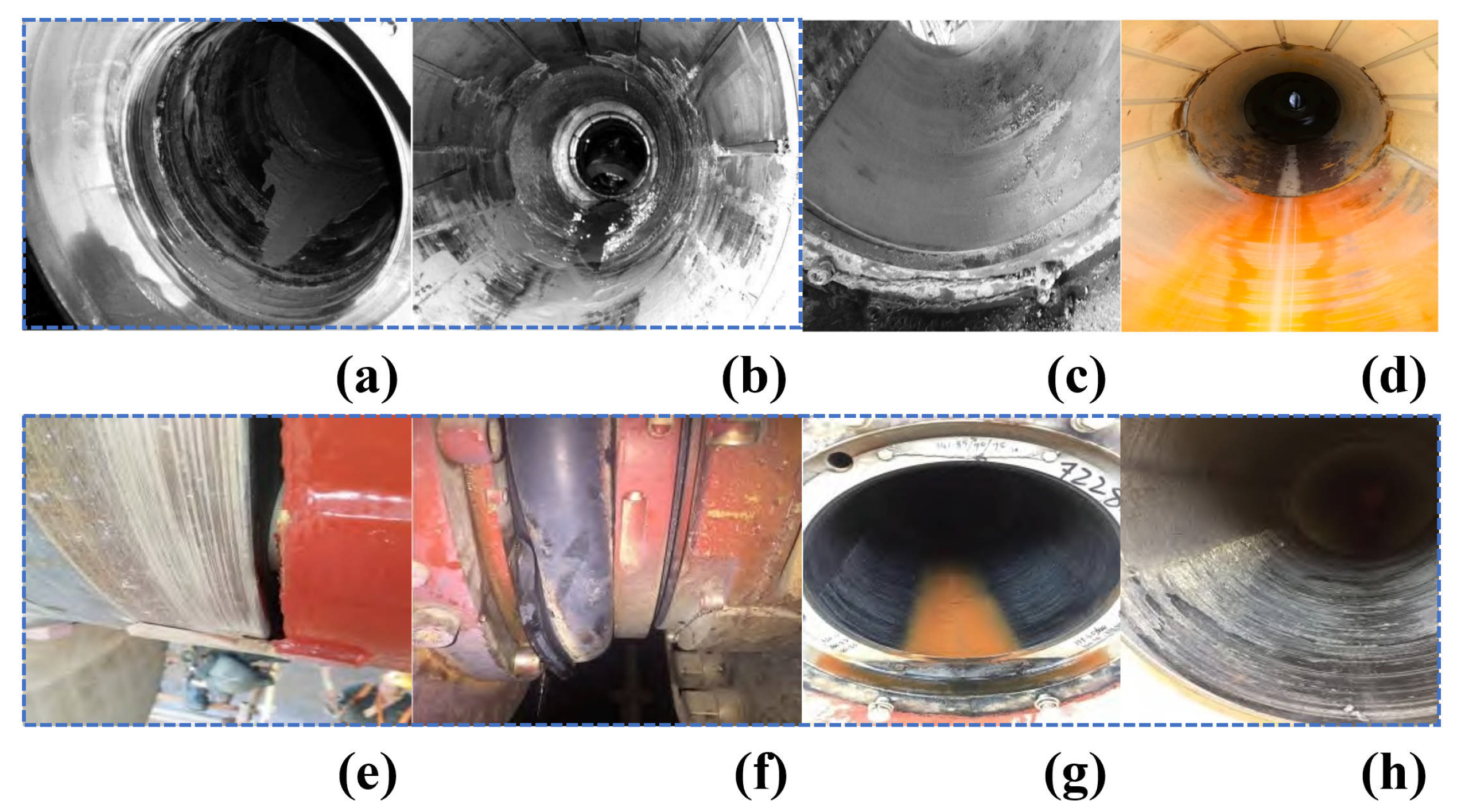
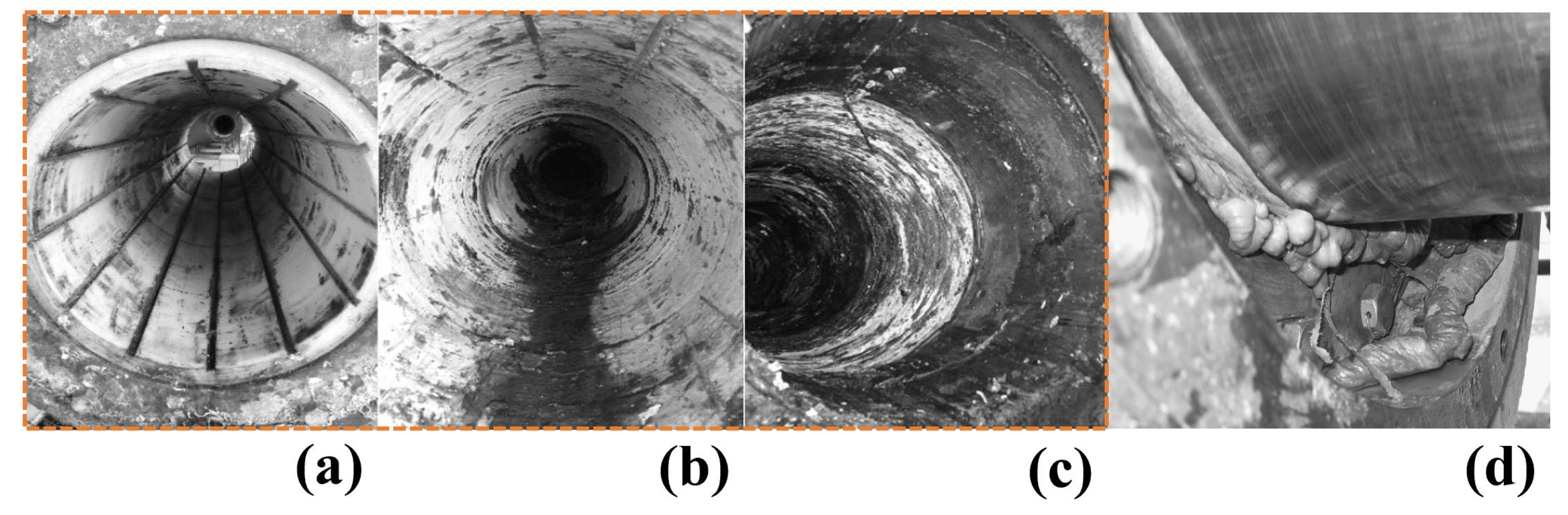
| [31] | 159.6 m bulk carrier/2010 | Long shaft system | Polymer material | Closed | Surface damage of about 3.00 mm on stern tube static ring, springs outside the dynamic ring blocked by sediment and cannot pop out automatically, severe wear on the surface of the dynamic ring; bearing gap 7.00 mm (normal value is 1.00 mm). Figure 2a,b show blockages of sediment in the middle and lower part of the flume, respectively. | Stern bearing operates under high sand concentration, high wear rate. |
| [32] | 16,000 t bulk carrier/1976 | Short shaft system | Lignum vitae | Closed | Excessive bearing wear up to 2.08 mm; overly large bearing gap, various degrees of wear on stern tube bronze sleeve. | Poor shaft alignment; stern tube seal failure. |
| [33] | 9600 GT freighter/2002 | Short shaft system | Polymer material | Open, seawater-lubricated | Front and rear stern tube bronze sleeves worn down to a depth of 3.00 mm, maximum bearing gap 6.00 mm (exceeding the limit value of 5.10 mm). | Shaft line subsidence deformation; excessive bearing gap; localized wear causing stress concentration. |
| [34] | Unlimited range dry cargo ship | Short shaft system | Cylon | Seawater-lubricated | Shaft centerline significantly exceeds normal range; partial uneven wear of stern tube bronze sleeve, abnormal shaft vibration. | Shaft centerline misalignment; propeller entangles ropes/nets. |
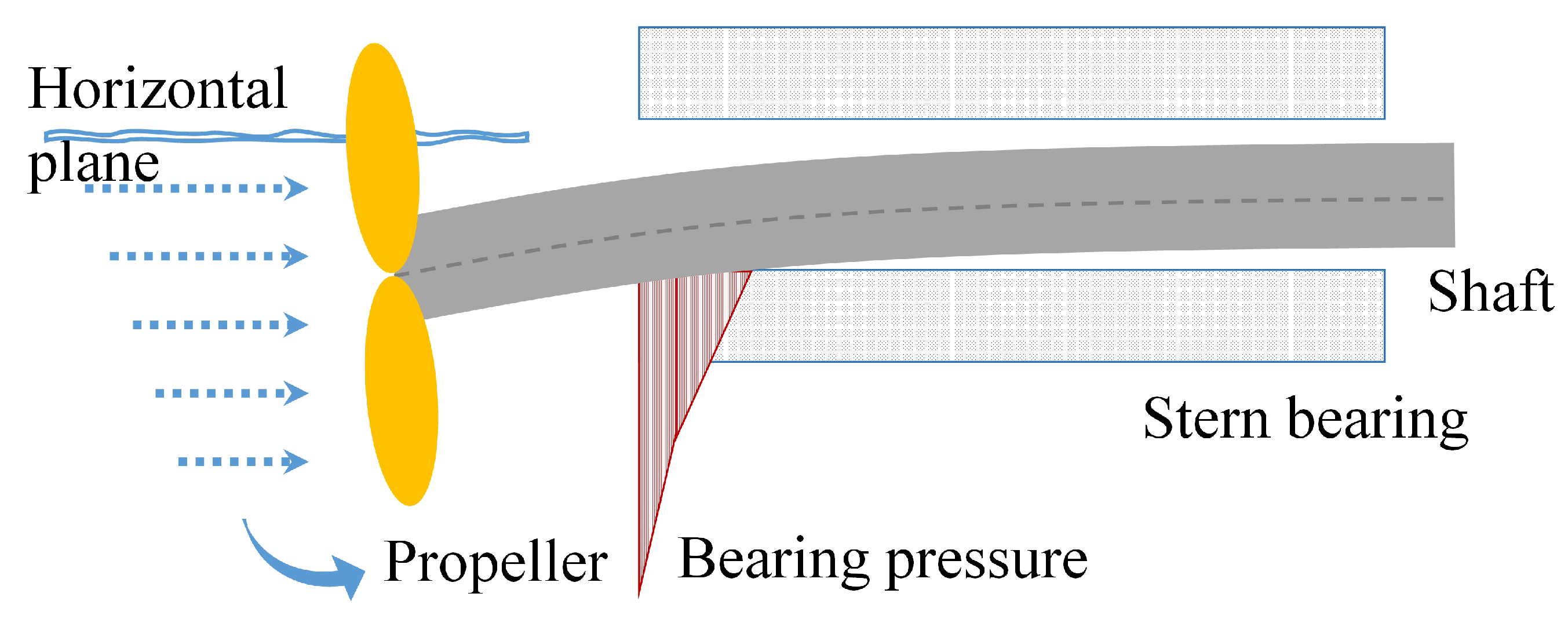
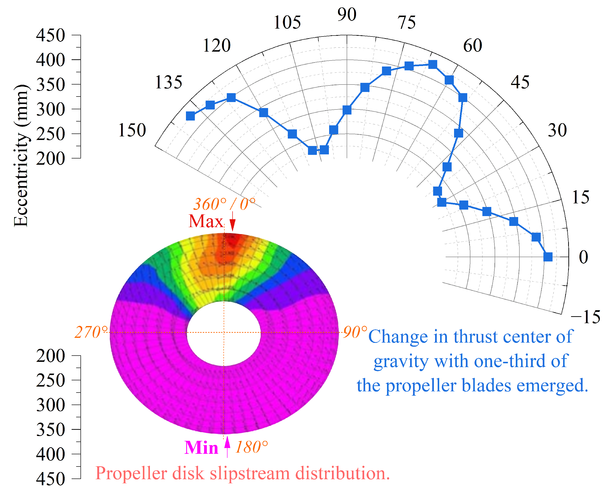
| [35] | Single-engine single-propeller bulk carrier | - | - | Closed | Traveling in light ballast condition in adverse sea conditions (Beaufort scale 9–11) with draft of 4.17 m at the bow and 7.80 m at the stern, leading to abnormal wear of the stern bearing. | Propeller emergence. |
| [36] | Electric propulsion test platform | - | Cylon | Closed | Severe wear on the stern tube bearing, stern shaft sinking; excessive vibration and noise at the stern tube. Figure 2c shows severe wear condition of the stern tube bearing. | Poor alignment, unreasonable load distribution; cavitation effect impacting water film load-bearing capacity, eroding bearing liner material. |
| [37] | China ship scientific research center | - | - | - | Obvious wear on the friction pair surfaces of the shaft and bearing; Figure 2d. | Poor lubrication of the stern bearing, causing friction vibration and noise. |
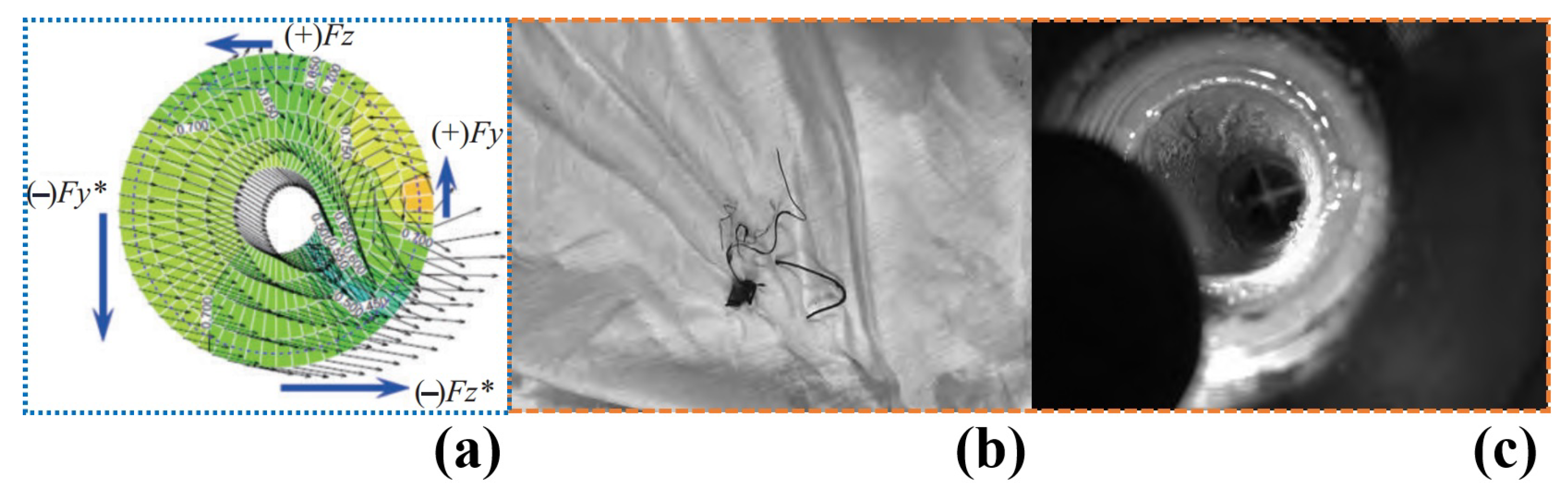
| [38] | 4600 t juice transport ship | Single stern tube bearing | Rubber | Closed, freshwater-lubricated | Fishnet knife in scraping state against propeller hub, as shown in Figure 2e, with a design gap of about 5.00 mm, hence it can be inferred that the bearing has worn down about 5.00 mm. Bearing wear leads to seal damage, shown in Figure 2f–h, illustrating the wear state at the aft and fore ends of the bearing, respectively. | Hull deformation at the stern hub causing shaft line changes, poor alignment; seal failure triggers bearing wear, followed by meltdown, further exacerbating seal damage. |
| Source | Ship | Shaft System | Liner Material | Bearing Structure | Failure or Malfunction | Cause of Failure |
|---|---|---|---|---|---|---|
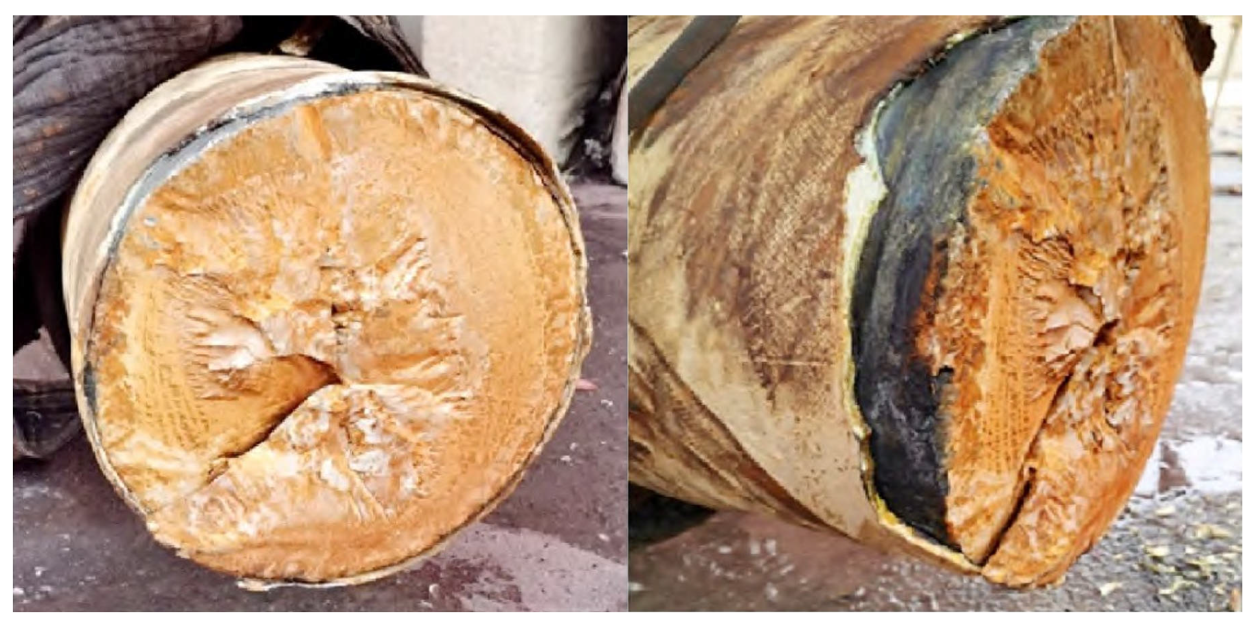
| [44] | A particular ship | Long shaft system | Polymer | Closed | Severe burning of the aft stern tube bearing and re-solidification of melted polymer material, with the bearing grooves blocked by the melted polymer material. Figure 6a–c show the high-temperature erosion and wear state of the stern frame bearing, aft stern tube bearing, and fore stern tube bearing, respectively. | Groove blockage prevented normal flow of cooling water, leading to bearing burn-out; misalignment of the shaft system indirectly caused bearing burn-out. |
| [45] | Gdansk University of Technology | Shaft diameter 350 mm | Polymer | Closed | Stern bearing overheating caused the polymer to melt; Figure 6d shows the melted polymer of the stern bearing. | Cooling system failure. |
| [46] | Datang 82 | Long shaft system | Polymer | Closed | Cooling water gushing from the fore stern seal at nearly 100 °C with a lot of steam leakage; stern bearing burnt out. | Cooling water pipe clogged. |
| [46] | Weilun 216 | - | Cylon | Open | Dry friction between the stern shaft and stern bearing; high temperature caused the nylon to melt and detach, sticking to the stern shaft; stern bearing burnt out. | Fishing net blocked the stern bearing cooling flume, causing cooling water to stop flowing. |
| No. | Monitoring Parameter Name | Unit |
|---|---|---|
| 1 | Torque | N·m |
| 2 | Rotational speed | r/min |
| 3 | Power | kW |
| 4 | Load force at front and rear ends | t |
| 5 | Lubricating water temperature at bearing inlet | °C |
| 6 | Lubricating water temperature at bearing outlet | °C |
| 7 | Water tank temperature | °C |
| 8 | Water tank liquid level height | mm |
| 9 | Lubricating water flow rate | L/min |
| 10 | Lubricating water pipeline pressure | MPa |
| 11 | Bearing friction coefficient (f) | - |
| Components and Parts | Material | Poisson’s Ratio | Elasticity Modulus (MPa) | Density (kg/m3) |
|---|---|---|---|---|
| Circumference: 0.28 | Circumference: 1080 | |||
| Bearing liner | SF-2A | Radial direction: 0.28 | Radial direction: 1510 | 1370 |
| Axial direction: 0.28 | Axial direction: 4020 | |||
| Shaft copper sleeve | ZCuSn10Zn2 | 0.35 | 1.00 × 10⁵ | 8500 |
| Shaft | 34CrMo1 | 0.25 | 2.07 × 10⁵ | 7800 |
| No. | n (r/min) | p (MPa) | Lr | Q (L/min) | T (°C) | Sc (kg/m3) | Sps (mm) | t (h) |
|---|---|---|---|---|---|---|---|---|
| 1 | - | - | - | - | - | - | - | >72.0 |
| 2 | 50/80/100/200/300/400/500/600 | 0.50 | 4:6 | 30 | 20.0 | 0 | 0 | - |
| 3 | 50/80/100/200/300/400/500/600 | 0.50 | 4:6 | 30 | 20.0 | 0 | 0 | 1.5 |
| 4 | 600/500/400/300/200/100/80/50 | 0.50 | 4:6 | 30 | 20.0 | 0 | 0 | 1.5 |
| 5 | 50/100/220/350/420/550/680/800/920/1050 | 0.50 | 4:6 | 30 | 20.0 | 0 | 0 | - |
| 6 | 50/60/80/100/150/200/300/350/400/450/500/600 | 0.20/0.30/0.40/0.50 | 4:6 | 30 | 20.0/32.0/39.0 | 0 | 0 | - |
| 7 | 314/597/691/880/1068 | 0.50 | 4:6 | 30 | 20.0 | 0 | 0 | - |
| 8 | 314/597/691/880/1068 | 0.50 | 4:6 | 30 | 20.0/24.0/28.0 | 0 | 0 | - |
| 9 | 50/60/80/100/150/200/300/400/500 | 0.20/0.30/0.40/0.50 | 4:6 | 30 | 20.0 | 0 | 0 | - |
| 10 | 314/597/691/880/1068 | 0.50 | 4:6 | 30 | 20.0 | 0.25 | <0.05 | - |
| 11 | 48/72/120/300/480 | 0.50 | 4:6 | 30 | 20.0/23.0/26.0 | 0.25 | <0.05 | - |
| 12 | 48/72/120/300/480 | 0.50/0.80/1.00/1.50 | 4:6 | 30 | 20.0 | 0.25 | <0.05 | - |
| 13 | Condition 1: Speeds of 314, 597, 691, 880, and 1068 r/min; durations of 2.5, 5, 10, 5, and 2.5 h; two cycles; 50 h; parameters as in Experiment 7. | |||||||
| 14 | Condition 2: Speeds of 314, 597, 691, 880, and 1068 r/min; durations of 2.5, 5, 10, 5, and 2.5 h; four cycles; 100 h; parameters as in Experiment 10. | |||||||
| 15 | Condition 3: Speeds of 48, 72, 120, 300, and 480 r/min; pressures of 0.8, 1.0, and 1.5 MPa; durations of 3 h each; for a total of two cycles, amounting to 90 h; parameters as in Experiment 10. | |||||||
Disclaimer/Publisher’s Note: The statements, opinions and data contained in all publications are solely those of the individual author(s) and contributor(s) and not of MDPI and/or the editor(s). MDPI and/or the editor(s) disclaim responsibility for any injury to people or property resulting from any ideas, methods, instructions or products referred to in the content. |
© 2024 by the authors. Licensee MDPI, Basel, Switzerland. This article is an open access article distributed under the terms and conditions of the Creative Commons Attribution (CC BY) license (https://creativecommons.org/licenses/by/4.0/).
Share and Cite
Chang, X.; Liu, J.; Yan, X.; Sun, F.; Zhu, H.; Wang, C. Experimental Study on the Effects of Controllable Parameters on the Healthy Operation of SF-2A Material Water-Lubricated Stern Bearing in Multi-Point Ultra-Long Shaft Systems of Ships. J. Mar. Sci. Eng. 2025, 13, 14. https://doi.org/10.3390/jmse13010014
Chang X, Liu J, Yan X, Sun F, Zhu H, Wang C. Experimental Study on the Effects of Controllable Parameters on the Healthy Operation of SF-2A Material Water-Lubricated Stern Bearing in Multi-Point Ultra-Long Shaft Systems of Ships. Journal of Marine Science and Engineering. 2025; 13(1):14. https://doi.org/10.3390/jmse13010014
Chicago/Turabian StyleChang, Xingshan, Jie Liu, Xinping Yan, Feng Sun, Hanhua Zhu, and Chengmin Wang. 2025. "Experimental Study on the Effects of Controllable Parameters on the Healthy Operation of SF-2A Material Water-Lubricated Stern Bearing in Multi-Point Ultra-Long Shaft Systems of Ships" Journal of Marine Science and Engineering 13, no. 1: 14. https://doi.org/10.3390/jmse13010014
APA StyleChang, X., Liu, J., Yan, X., Sun, F., Zhu, H., & Wang, C. (2025). Experimental Study on the Effects of Controllable Parameters on the Healthy Operation of SF-2A Material Water-Lubricated Stern Bearing in Multi-Point Ultra-Long Shaft Systems of Ships. Journal of Marine Science and Engineering, 13(1), 14. https://doi.org/10.3390/jmse13010014