Article

A Time-Delay Overlapping Modulation-Based Maritime High-Speed and High-Spectral-Efficiency Communication Technology

College of Information Science and Technology, Dalian Maritime University, Dalian 116026, China
*
Author to whom correspondence should be addressed.
J. Mar. Sci. Eng. 2025, 13(2), 345; https://doi.org/10.3390/jmse13020345
Submission received: 14 January 2025 / Revised: 6 February 2025 / Accepted: 11 February 2025 / Published: 13 February 2025
(This article belongs to the Section Ocean Engineering)

Abstract

:
To simultaneously address dual demands on the spectral efficiency and the data transmission rate of maritime communications, in this paper, a novel maritime communication technology based on time-delay overlapping modulation (TDOM) is proposed. In TDOM, multiple carriers are delayed in turn and directly overlapped in the time domain to form the communication symbol. In this way, the strict orthogonality between carriers can be broken through, indicating that the frequency interval between carriers can be much narrower than ever. In other words, TDOM can achieve non-orthogonal communication and realize both higher spectral efficiency and a higher maritime communication rate. The system architecture is designed, and its performance is analyzed and compared with that of other typical maritime communication technologies such as the very-high-frequency data exchange system (VDES). It is shown that TDOM can reach up to 20 times the peak communication rate and the spectral efficiency of VDES. As a digital modulation technology implemented in the physical layer, the proposed TDOM can be extended to other communication systems such as satellite communications or 4G/5G based off-shore communications.

1. Introduction

Maritime communication technologies achieve information exchange between ships and between ships and shore, and have always played an important role in ensuring the efficient and stable operation of maritime activities. Various modern maritime activities, such as offshore aquaculture as well as maritime search and rescue, require the transmission of real-time video information and other broadband services, requiring maritime communication systems to have a higher data transmission rate while being able to cover long distances. In addition, with the concept of marine Internet of Things, more maritime infrastructure, such as ships, buoys, unmanned ships, drones, etc., will have access to the maritime communications system and network, requiring maritime communication technology to have a higher spectral efficiency to accommodate more maritime communication users. Therefore, the establishment of a maritime communication technology with both a higher data transmission rate and higher spectral efficiency is important for the current and future operation of maritime activities.
In open-sea regions, satellite communication is the main data transmission approach, and common satellite communication systems include the Iridium system [1], the Very Small Aperture Terminal (VSAT) [2] and the Inmarsat system [3,4]. In satellite communication systems, the available bandwidth is divided into multiple separate frequency sub-channels, and frequency guard bands are set between sub-channels to avoid interferences. For each sub-channel, Quadrature Phase Shift Keying (QPSK) is the most widely used modulation technology, and 8-Phase Shift Keying (8PSK) and 16-Amplitude Shift Keying (16ASK) are utilized in the fifth-generation Inmarsat satellite communication system to provide higher data rates. Meanwhile, communications between vessels in open-sea regions can also be implemented in the medium-frequency/high-frequency/very-high-frequency (MF/HF/VHF) band, and typical technologies include navigation telex (NAVTEX), the automatic identification system (AIS) [5] and the VHF data exchange system (VDES) [6]. According to the standard [6], a 100 kHz VDES demo utilizes multi-carrier modulation, which comprises 32 equal-power subcarriers with 16-QAM modulation of each subcarrier, provides a data rate of 307.2 kbit/s, and has a frequency interval between sub-channels of 2.7 kHz (not orthogonal), indicating that the spectrum of sub-channels can be slightly overlapped.
As offshore regions can be covered by base stations on the coast, various terrestrial communication technologies can be utilized to support data transmission between vessels and the coast. From 2010, many projects have been implemented, such as TRITON [7], Marcom [8], NANET [9] and BLUECOM+ [10,11], and the involved technologies are mainly WiFi [12], WiMAX [13,14,15,16], LTE [17,18,19], etc. For these technologies, orthogonal frequency division multiplexing (OFDM) is the most widely used technology, in which frequencies of sub-channels are orthogonal to each other, and spectrums of sub-channels can be overlapped to achieve higher spectral efficiency. For each sub-channel, 16/64/256-QAM modulation is used to realize a high data rate and support multi-user access.
Although 4G/5G-based wireless communications can achieve a high data transmission rate, their base stations can only be constructed on land along the coastline, and the communication services can therefore only cover offshore regions. The VHF Data Exchange System (VDES) is a third-generation maritime communication system established by the World Radiocommunication Conference. AIS, VDES adds ASM and VDE can not only meet the requirement of close-range bi-direction data exchange between ships and ships, but can also achieve long-distance data exchange between ships and coasts on a global scale through satellites. However, the peak communication rate of the VDES is only 307.2 kbps, which means that it cannot meet the current and even future communication rate requirements for maritime services. Therefore, this paper proposes a novel high-spectral-efficiency maritime communication technique based on time-delay overlapping modulation (TDOM) and investigates its communication performance under maritime communication channels. Different from the traditional multi-carrier modulation technique, the core of TDOM lies in the fact that multiple carriers are delayed in turn and directly overlapped in the time domain. This will resolve the orthogonality constraint of traditional multicarrier modulation on carrier frequency and achieve non-orthogonal communications. Therefore, higher spectral efficiency and a higher data transmission rate can be achieved.
This rest of this paper is organized as follows. Section 2 describes the transceiver structure of the proposed TDOM and its modulation and demodulation principles. Section 3 analyses the performance of the system, such as the spectral efficiency, complexity, and the origin of the bit error rate. Section 4 gives the simulation results and discussions, and Section 5 concludes the paper.

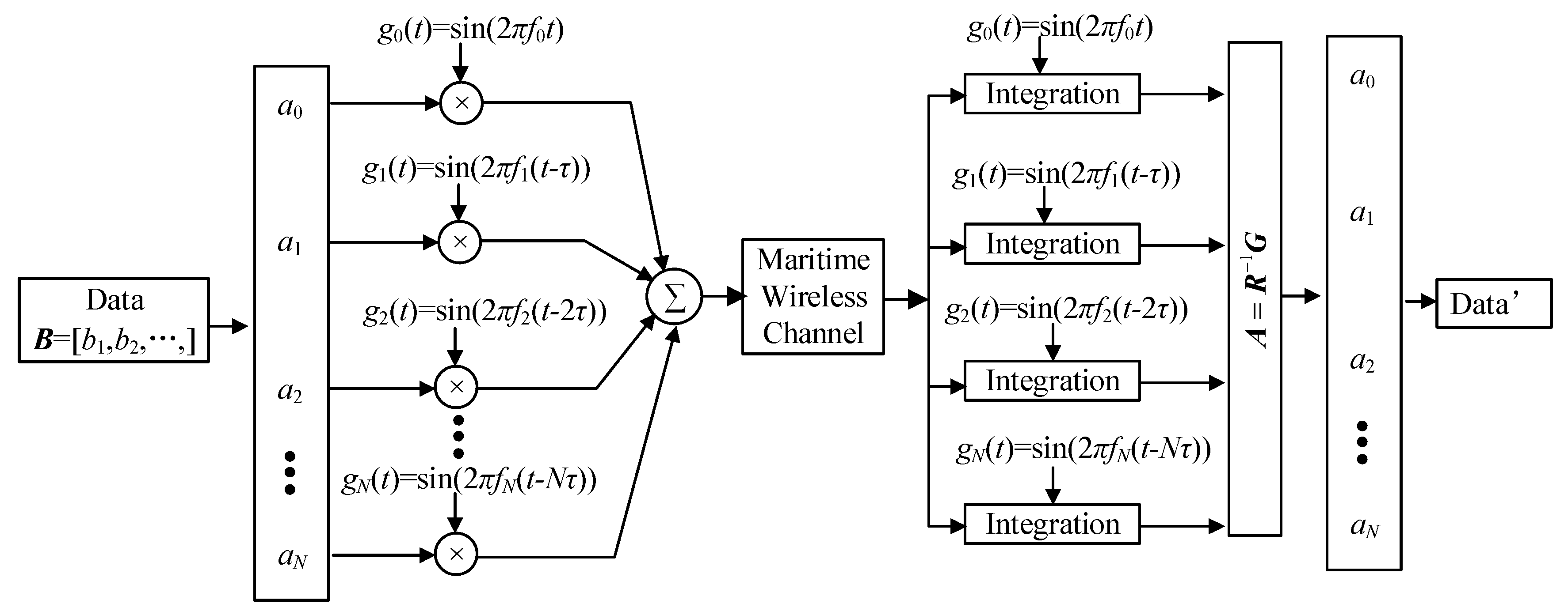
2. System Architecture

2.1. Transmitter

The block diagram of the proposed TDOM is shown in Figure 1. At the transmitter, according to the amplitude mapping rule shown in Table 1, the serial binary data bits b= [b1, b2, …] are firstly converted into modulation amplitude an (n = 0, …, N, where (N + 1) is the total number of carriers). Then, multiple carriers (sinusoidal waves, as an example) are modulated using an. After modulation, each carrier is sequentially delayed and directly superimposed in the time domain, as shown in Figure 2. The delay time τ can be set arbitrarily. In this paper, all the delays τ are made the same, i.e., τ1 = τ2 = … = T/N, where T is the duration of one carrier, and the duration of one TDOM symbol is set to be 2T. The communication symbol S(t) is shown in Equation (1), where an represents the nth modulation amplitude, fn represents the frequency of the nth carrier, and τn represents the delay between carriers. When n = 0, τ0 = 0.
S t = n = 0 N a n s i n 2 π f n t τ n
It is worth mentioning that the TDOM does not have any restriction on the carrier frequency fn. Firstly, orthogonality between all frequencies is no longer required. This means that the frequency interval between each carrier can be narrower and the system can therefore achieve higher spectral efficiency. In addition, the carrier frequency can be set very flexibly. All carrier frequencies can be different, i.e., f0f1 ≠ … ≠ fN, or all frequencies can be the same, i.e., f0 = f1 = … = fN. When all carriers have the same frequency, the TDOM system evolves into a single-carrier communication system, and it can carry multiple information bits in only one single-frequency subchannel, providing the highest spectral efficiency.

2.2. Receiver

This subsection introduces the demodulation principle of the TDOM system. As carriers are not orthogonal any more, band-pass filters or fast Fourier Transformation (FFT) in traditional multi-carrier communication systems can no longer work. Therefore, in the proposed TDOM, a system of linear equations for all information an is established to demodulate the information.
Taking a back-to-back system as an example. When the signal is received at the receiver, the first carrier, sin(2πf0t), is used to perform a coherence computation with the received signal to obtain the first linear equation about all modulation amplitudes an, i.e.,
G 0 = 0 T s i n 2 π f 0 t × S t d t       = 0 T s i n 2 π f 0 t × a 0 s i n 2 π f 0 t + a 1 s i n 2 π f 1 t τ + a 2 s i n 2 π f 2 t 2 τ               + + a N s i n 2 π f N t N τ d t       = a 0 r 00 + a 1 r 01 + + a N r 0 N ,
where r 00 = 0 T s i n 2 π f 0 t × s i n 2 π f 0 t d t , and so on. Then, the system uses the second carrier sin[2πf1(tτ)] to perform a coherent computation with the received signal to obtain the second linear equation for all modulation amplitudes an, i.e.,
G 1 = 0 T s i n 2 π f 1 t τ × S t d t       = 0 T s i n 2 π f 1 t τ × a 0 s i n 2 π f 0 t + a 1 s i n 2 π f 1 t τ + a 2 k s i n 2 π f 2 t 2 τ               + + a N s i n 2 π f N t N τ d t       = a 0 r 10 + a 1 r 11 + + a N r 1 N ,
where r 10 = 0 T s i n 2 π f 0 ( t τ ) × s i n 2 π f 0 t d t , and so on. After coherent computations with the received signal using all carriers, a system of linear equations can be obtained, i.e.,
R A = G
where R = r 00 r 0 N r N 1 r N N , A = a 0 a N , G = G 0 G N . It is worth noting that the matrix R is an (N + 1)-order full-rank Toplitz matrix. Therefore, there exists an inverse matrix, R−1. Then, the modulation amplitude of each carrier an can be obtained by solving the system of linear equations, i.e.,
A = R 1 G
Finally, the magnitude is converted to binary bits data according to the magnitude mapping rules given in Table 1.

2.3. Maritime Channel

The maritime communication channel model used in this paper is shown in Figure 3. When the sea surface is undulating due to sea winds and the transceivers are vibrating up and down due to waves, the electromagnetic wave signals, in addition to being affected by Gaussian white noise, also experience multipath interferences caused by reflections such as specular and diffuse reflections, as shown in Figure 3. Here we default that there is only one specular reflection path. However, due to the effect of wind, waves and sea climate on the sea surface, diffuse reflection points are randomly distributed around the specular reflection points, which makes an “effective reflection region”. Therefore, it is necessary to determine the time-delay caused by the diffuse reflection point. According to the standard, in the 100 kHz maritime channel environment, reflections are mainly contained in the first 10.4 μs of the symbol, but there are extreme cases where reflections occur at 50 μs [20]. The literature [21] gives a maximum delay of 46.2848 μs for a shore-based antenna of a 80 m height and a shipboard antenna of a 25 m height. Therefore, in this paper, the performance of the proposed TDOM system will be analyzed separately for two types of maritime communication channels, i.e., a single-path additive Gaussian white noise channel and a maritime multipath channel that includes one line of sight (LoS) path and multiple reflection paths. During simulation, three reflection paths are considered, i.e., two diffuse reflection paths which cause a delay of 50 μs and 10 μs at the maximum and minimum, respectively, and one specular reflection path which causes a negligible propagation delay. Meanwhile, during the simulation, in order to facilitate the understanding of the results under maritime multipath channels, the impact of system parameters on communication performance under the additive Gaussian white noise (AWGN) channel is firstly tested [22].
The ratio between the signal passing through the specular reflection path and the Los transmission signal is [23]
V Specular V LoS = ρ s G ant Γ v ρ veg ,
where VSpecular and VLoS represents the voltage of the signal passing through the specular reflection path and the LoS path, respectively. ρs is the specular reflection coefficient, and Γv is the Fresnel reflection coefficient, i.e.,
ρ s = exp 2 2 π σ h sin φ λ 2 ,
Γ v = ε c sin φ ε c cos 2 φ ε c sin φ + ε c cos 2 φ .
where σh, φ, λ, and εc are, respectively, the rms surface height variation, the grazing angle, the wavelength, and the surface dielectric constant. In this paper, σh is set to be 0.3 m, assuming that the wave is gentle [23].
Moreover, the ratio between the strength of the signal passing the diffuse reflection path and the Los transmission signal is [23]
V Diffuse V LoS = 1 4 π R R 1 R 2 2 1 β 0 2 exp β 2 β 0 2 d A Γ v ρ veg G ant ρ roughness S f .
where R, R1 and R2 are the distance of the LoS path, the distance from the transmitter to the reflection point and from the reflection point to the receiver, respectively. In this paper, R is set to be 5 km, and R1 and R2 are set to be 100 m and 10 m, respectively. β0 is the angle between the bisector of the R1 and R2 rays and the local vertical, and β is the mean square value of the surface slope over the region of interest. ρroughness, S f , and dA are the roughness factor, the shadowing factor, and an arbitrary small patch of area lying on the effective reflection region, respectively.

3. Performance Analysis

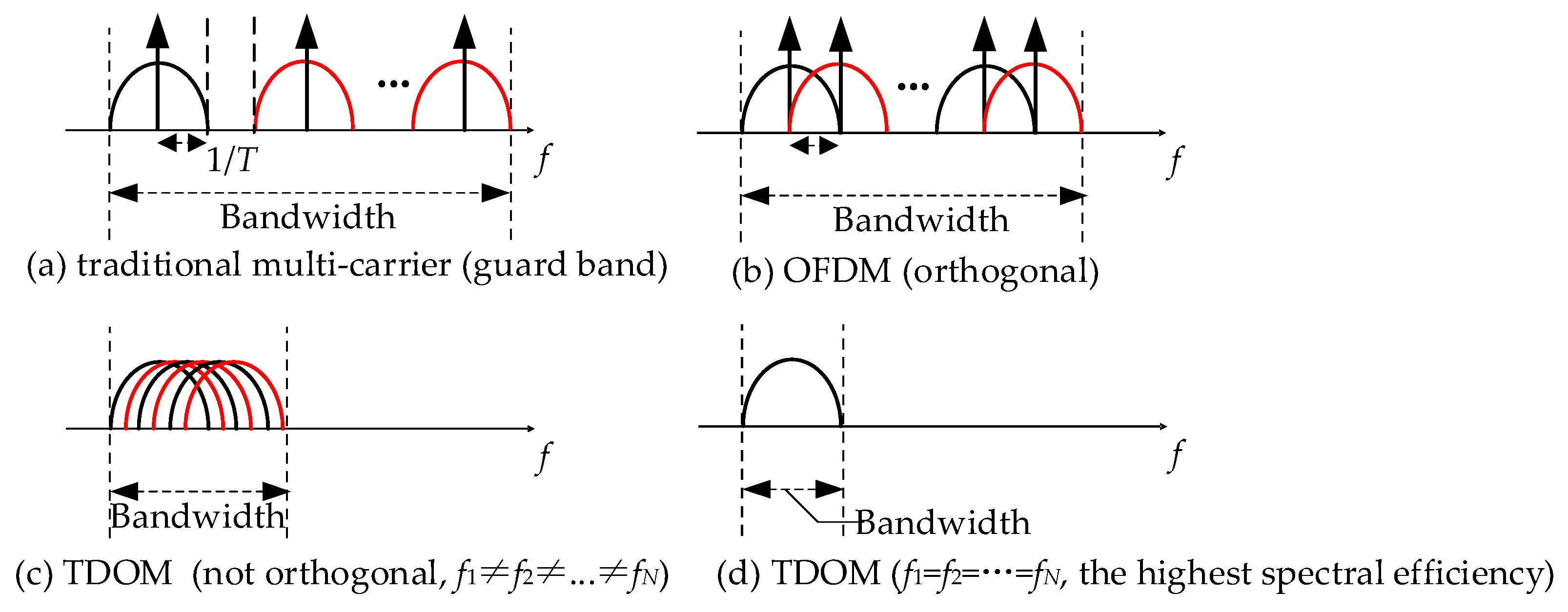
3.1. Spectral Efficiency

As orthogonality between carriers is no longer strictly required, the proposed TDOM has higher spectral efficiency than traditional multi-carrier modulations. The carrier frequency distributions for conventional multicarrier communications, orthogonal frequency division multiplexing (OFDM), and TDOM are shown in Figure 4. Conventional multicarrier communications require a guard band between each carrier to prevent mutual interference. OFDM allow carriers to overlap in the frequency domain, but still require strict orthogonality between carriers. The TDOM can further narrow the frequency interval between each carrier to make better use of the spectrum resources. This is of great significance for maritime communications, where the spectrum resources are extremely tight, and the saved frequency resources can be used to carry more users of maritime communications. Specifically, when all carrier frequencies are the same, as shown in Figure 4d, the TDOM can achieve the highest spectral efficiency.
If the time duration on one carrier is T, the time duration of a TDOM symbol is 2T. Then, suppose there are N carriers within one symbol, and each carrier conveys b information bits, the communication rate of the TDOM system is
rate TDOM = N b 2 T .
Meanwhile, in this paper, we aim to discover the highest spectral efficiency that the TDOM can achieve. Therefore, in the rest of this paper, we assume that all carriers within one TDOM symbol have the same frequency, i.e., f1 = f2 = … = fN. At this time, the bandwidth of the TDOM is same to that of one carrier, i.e., 2/T. Therefore, the spectral efficiency (SE) of the TDOM system is
SE TDOM = rate TDOM bandwidth TDOM = N b / 2 T 2 / T = N b 4 .
From Equations (10) and (11), the communication rate and the spectral efficiency of the TDOM system are both proportional to the total number of carriers within one symbol (N) and the information bit that each carrier can convey (b). As shown in Table 1, in this paper, each carrier is set to convey 2 bits, i.e., b = 2. Then, the highest communication rate of TDOM depends on N. To compare with the traditional maritime communication technology, i.e., a very-high-frequency data exchange system (VDES), the bandwidth of the TDOM is set to be less than the peak bandwidth of VDES, i.e., 2 T 100 KHz .

3.2. Complexity

In this paper, the computation complexity is defined as the total number of multiplications and additions which is required to generate the communication symbol and demodulate information. For VDES, N multiplications and (N − 1) additions are required to form a symbol. To demodulate N information bits, N multiplications and N additions are required. Thus, the total complexity of VDES is 2N multiplication and 2N − 1 addition. The complexity of TDOM is similar to that of VDES, except for the time-delay. Fortunately, the time-delay can be realized by means of digital signal processing, which is relatively simple to implement. At the receiver, solving the system of linear equations introduces additional complexity. It is well known that the complexity of solving a system of equations of dimension N is O(N3). Therefore, the complexity of TDOM is larger than that of VDES. In addition, OFDM-DCSK requires N IFFT and FFT to demodulate N information bits, and its complexity is also smaller than that of TDOM. However, the TDOM achieves a higher spectral efficiency and saves more maritime communication spectrum resources, which will enable maritime communication networks to achieve higher communication rates or accommodate more users. Meanwhile, when updating the traditional transceiver using TDOM, only the baseband modem module needs to be replaced, and other modules such as the RF modem module do not need any changes. Therefore, the system upgrading cost is low.

3.3. BER Source Analysis

Noise and multipath interference in the maritime communication channel will affect the system performance. Taking the additive Gaussian white noise (AWGN) channel as an example, the received signal can be expressed as
r ( t ) = s ( t ) + n ( t ) ,
where r(t), s(t) and n(t) represent the received signal, transmitted signal and Gaussian white noise vectors, respectively. It can be seen that the presence of noise will cause the coherent computation to induce a deviation, which can be denoted as ΔG, and therefore the solution of the system of linear equations must have a deviation, ΔA. Then, Equation (5) will become
A + Δ A = R 1 G + Δ G .
Since RAG, we have
Δ A = R 1 Δ G .
It can be seen that noise directly causes the deviation in the system of linear equations. According to the nature of the matrix norm, we have
Δ A R 1 Δ G .
It can be seen that the deviation ΔA can be decreased by reducing the norm of the matrix R−1. From Equations (2) and (3), it can be seen that the elements of matrix R are related to carrier parameters, such as the frequency f, delay τ, and the total number of carriers N. Therefore, to ensure good system performance, the carrier parameters must be designed appropriately.
In the maritime multipath channel, the performance of the TDOM will be severely deteriorated because delays have been artificially introduced into the communication symbol. These delays, superimposed on the delays in the multipath channel, will cause serious interference to the system of linear equations constructed at the receiver. Assuming that the total number of paths is L, the delay of each path is τl (l = 1, …, L), and the path loss is αl, the received signal r(t) will become
r t = l = 1 L α l s t τ l + n t = a 0 l = 1 L α l s i n 2 π f 0 t τ l + a 1 l = 1 L α l s i n 2 π f 1 t τ τ l + + a N l = 1 L α l s i n 2 π f N t N τ τ l + n t ,
At this point, the coherence computation will become
G n = 0 T s i n 2 π f n t n τ × r t = 0 T s i n 2 π f n t n τ × a 0 l = 1 L α l s i n 2 π f 0 t τ l + a 1 l = 1 L α l s i n 2 π f 1 t τ τ l + + a N l = 1 L α l s i n 2 π f N t N τ τ l + n t d t = a 0 r n 0 + a 1 r n 1 + + a N r n N + Δ G n , n = 0 , , N
where
r i j = 0 T s i n 2 π f i t i τ × l = 1 L α l s i n 2 π f i t j τ τ l d t , i = 0 , , N , j = 0 , , N
Δ G n = 0 T s i n 2 π f n t n τ × n t d t .
From the above analysis, it can be seen that the right-side term of the equation RA = G contains not only the interference from noise, but also the inter-carrier interference (ICI) from multipath channels. Compared with the noise, the interference of the multipath channel will create great errors in the solution of the linear equation system. Meanwhile, the TDOM system will also suffer severe inter-symbol-interference (ISI) in the maritime multipath channel. Therefore, in multipath channels, channel estimation and channel equalization methods must be adopted to weaken the ISI and ICI to ensure good communication performance. It is worth noting that, for the TDOM, a simpler channel estimation and channel equalization method that does not require the accurate knowledge of the channel state information can be implemented. Firstly, a pilot signal P(t) needs to be inserted before each frame of TDOM symbols, which can be expressed as follows:
P t = n = 0 N s i n 2 π f n t τ n .
Then, at the receiver side, the received pilot Pr(t) is firstly separated from the communication symbol r(t), and fast Fourier transform (FFT) is conducted on Pr(t) and P(t) to obtain the channel state information H(f), i.e.,
H f = F F T P r t F F T P t ,
where H(f) represents the frequency response of the channel, and FFT (·) is the fast Fourier transformation operator. Then, an FFT operation is performed on the received signal r(t), and channel equalization is completed as follows,
R f = F F T r t H f .
Then, the received signal in the time domain is achieved by an inverse fast Fourier transform (IFFT) operation, as follows:
r t = I F F T R f .
where IFFT(·) is the IFFT operator. Finally, r’(t) is sent to the receiver to demodulate the transmitted information.
In addition, to cope with inter-symbol interference (ISI), a zero prefix (ZP) is inserted between two TDOM communication symbols and its duration is made to be longer than the maximum delay caused by a multipath channel.

4. Simulation Results

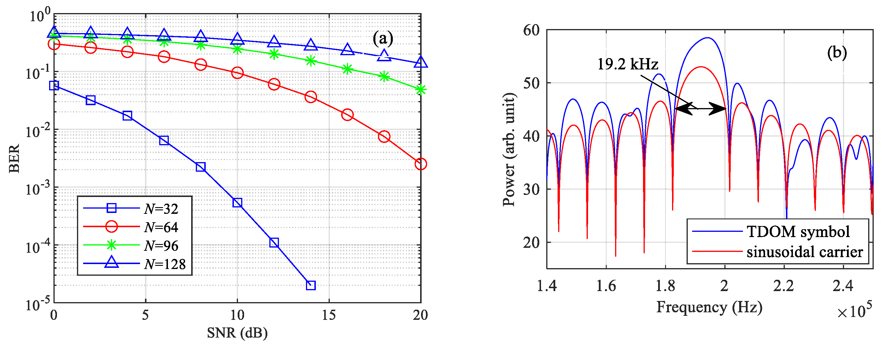
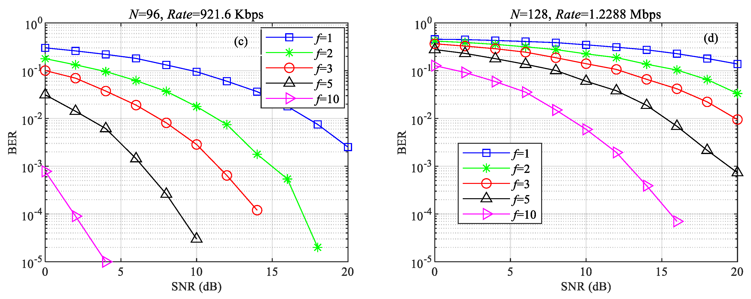
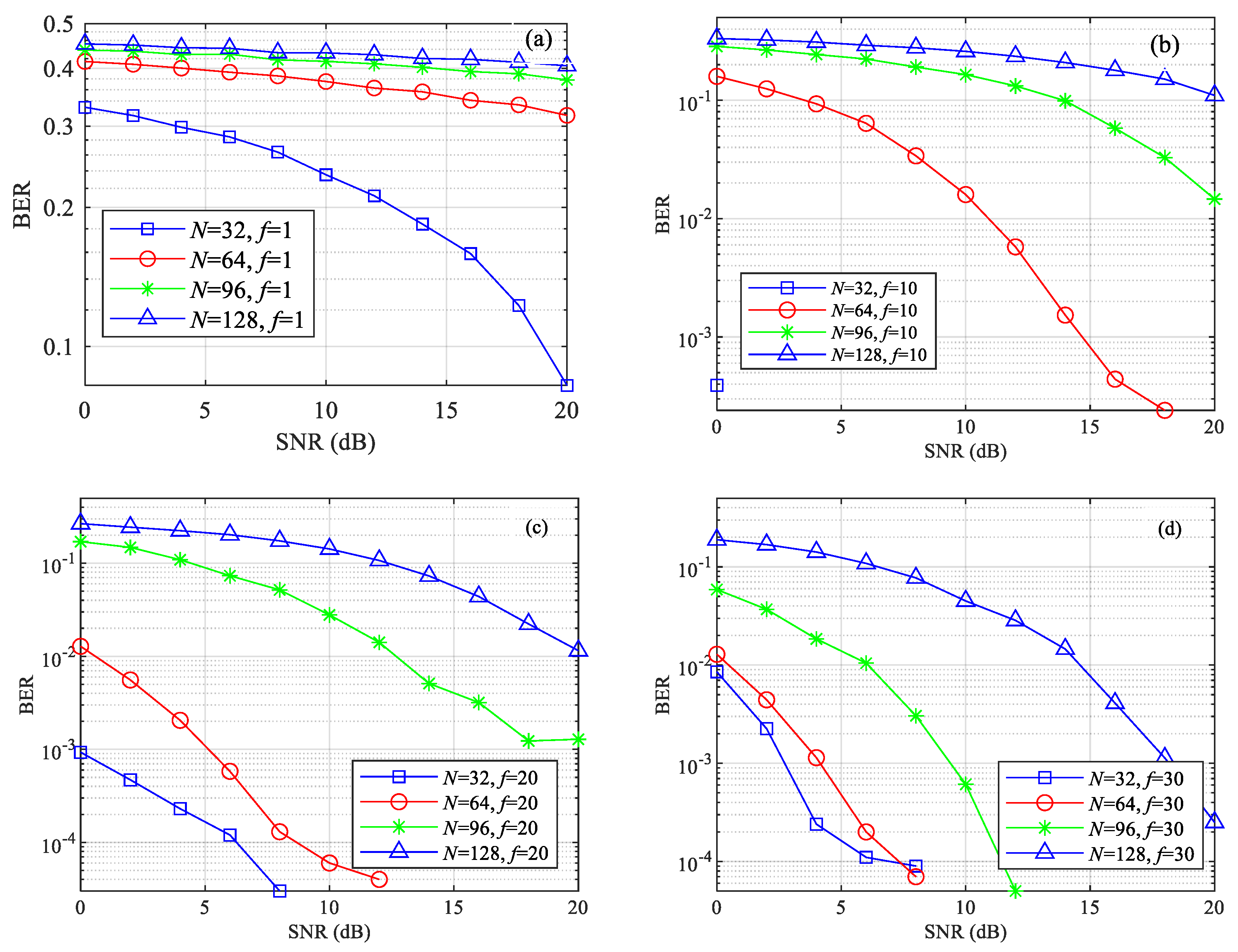
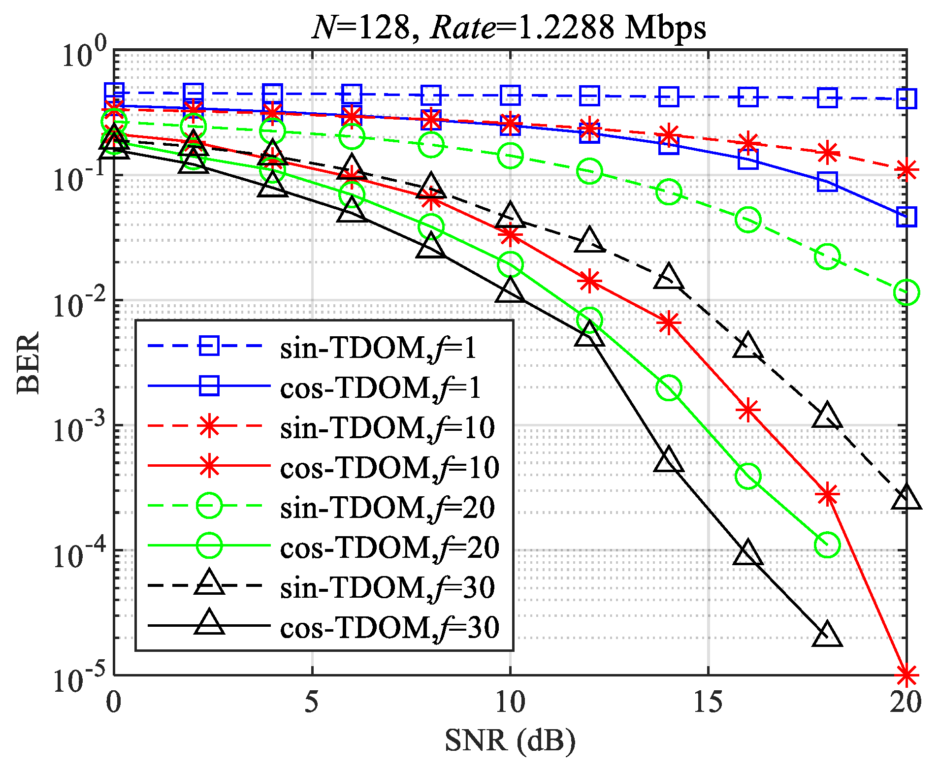
4.1. System Performance

In this subsection, we take the very-high-frequency (VHF) band as an instance with which to analyze the performance of the proposed TDOM system. The simulation is performed using Matlab R2023b. According to the M.1842-1 standard, the peak bandwidth of the maritime VHF band is 100 kHz [20]. This bandwidth is divided into 32 frequency subchannels, and the frequency spacing is 2.7 kHz. Meanwhile, 16QAM modulation is implemented in each subchannel. Therefore, each VDES symbol carries 32 × 2 = 64 bits of data. As the symbol rate is 2400 symbol/s, the peak data rate of VDES is 64 (bit/symbol) × 2400 (symbol/s) = 302.7 kbps [20]. It should be noted that the reason for choosing a symbol rate of 2400 symbol/s is to obtain a long symbol duration to combat the multipath interference in maritime communication channels. The AIS system can also use a symbol rate of 4800 symbol/s to achieve the same purpose. In this paper, the TDOM symbol rate is set to be 4800 symbol/s. Meanwhile, we make f0 = f1 = … = fN, which means that the TDOM can realize the highest spectral efficiency.
The performance of the TDOM system under AWGN channel is shown in Figure 5a. It can be seen that the system has good communication performance when the number of carriers is 32. From Table 1, each carrier conveys 2 bits, so the communication rate of the TDOM system is
2 bit / carrier × 32 carrier / symbol × 4800 symbol / s = 307.2 kbit / s
At this point, the peak rate of the current VHF data transmission system (VDES) has been reached. It is worth mentioning that, as FFT is no longer used in the receiver, the total number of carriers within one TDOM symbol is no longer limited to be an exponent number of 2 and can be set to be any value. Here, we take 64, 96 and 128, for instance. When the total number of carriers N is increased to more than 32, the communication performance of the system starts to degrade, which is due to the fact that the norm of the matrix R−1 rises with the number of carriers, resulting in an increase in the BER of the system, as shown in Table 2. This coincides with the theoretical analysis results in Section 3.3. Meanwhile, the spectrum of TDOM symbols is given in Figure 5b. It can be seen that the bandwidth occupied by the whole symbol is the same as that of a single subcarrier since all carriers within the symbol have the same frequency. According to the symbol construction principle shown in Figure 2, the duration of the whole symbol is twice the duration of a single carrier, so the duration of a single subcarrier is (1/9600) s. Therefore, the bandwidth of the symbol is 19.2 kHz, and the spectrum efficiency (SE) of the system can be expressed as Equation (19).
S E T D O M = 307.2 kbit / s / 19.2 kHz = 16 bit / s / Hz .
Changing the form of the carrier will change the norm of the matrix R−1 and therefore improve the communication performance of the whole TDOM system. Results in Figure 5 default that f0 = f1 = … = fN = 1, which means that there is only one sine or cosine-wave cycle in the carrier duration T. Figure 6 shows the effect of the carrier frequency f on the communication performance when N is 32, 64, 96 and 128. It can be seen that increasing the frequency f will improve the communication performance of the whole system. This is due to the fact that the norm of the matrix R−1 decreases when the carrier frequency f is increased, as shown in Table 3. When the carrier frequency f is increased to 5, the TDOM system with 64 carriers/symbol can achieve a communication performance similar to that of the TDOM system with 32 carriers/symbol, as shown in Figure 6b. The system communication rate at this point is twice that of Equation (18), i.e.,
2 bit / carrier × 64 carrier / symbol × 4800 symbol / s = 614.4 kbit / s
When the carrier frequency is increased to 10, TDOM systems with both 96 and 128 carriers/symbol can achieve better communication performance, as shown in Figure 6c,d. The peak data transmission rate and spectral efficiency of the system at this point are shown in Equations (21) and (22), respectively:
2 bit / carrier × 128 carrier / symbol × 4800 symbol / s = 1.2288 Mbit / s
S E T D O M = 1.2288 Mbit / s / 19.2 kHz = 64 bit / s / Hz .
Meanwhile, the spectral efficiency of the VDES system is shown in Equation (23). Therefore, the data transmission rate and spectral efficiency of TDOM is are 4 times and 20 times, respectively, of those of the VDES system, as shown in Equations (24) and (25):
S E V D E S = 307.2 kbit / s / 100 kHz = 3.072 bit / s / Hz .
R a t e T D O M R a t e V D E S = 1.288 Mbps 307.2 Kbps = 4 ,
S E T D O M S E V D E S = 64 bit / s / Hz 3.072 bit / s / Hz 20 .
The communication performance of the TDOM system under the maritime multipath channel is shown in Figure 7. It can be seen that the impact of multipath interference on the communication performance of TDOM is very serious, even with the channel estimation and channel equalization method. When N is increased to more than 64, the BER is high in the high signal-to-noise (SNR) region. Figure 7b shows the communication performance of TDOM systems with f equals to 10. It can be seen that the communication performance of all TDOM systems is improved, which is consistent with the aforementioned theoretical analysis and numerical simulation. When f is increased to 20, the communication performance of the TDOM system with 64 carriers per symbol is comparable to its performance in the AWGN channel, as shown in Figure 7c. When f is raised to 30, the communication performance of the TDOM system with 96 carriers per symbol also is also comparable to its performance in the AWGN channel, as shown in Figure 7d. However, the communication performance of the TDOM system with 128 carriers per symbol is still poor.
In order to further improve the performance of the TDOM system with 128 carriers per symbol, the form of the carriers is changed from sine to cosine, and the communication performance of the system is shown in Figure 8. It can be seen that the communication performance of the cos-TDOM system is better than that of the sin-TDOM system for all carrier frequencies. When the carrier frequency is raised to 30, the performance of the cos-TDOM with 128 carriers per symbol is comparable to the performance of the sin-TDOM system with 32 carriers per symbol in the AWGN channel. At this point, the communication rate of the TDOM system is 4 times of that of the VDES, and the spectral efficiency is 20 times higher than that of the VDES. Table 4 gives the norm of the matrix R−1 for sin and cos-TDOM. It can be seen that the cosine form carriers can further reduce the norm of matrix R−1 and thus improve the communication performance of the TDOM system.

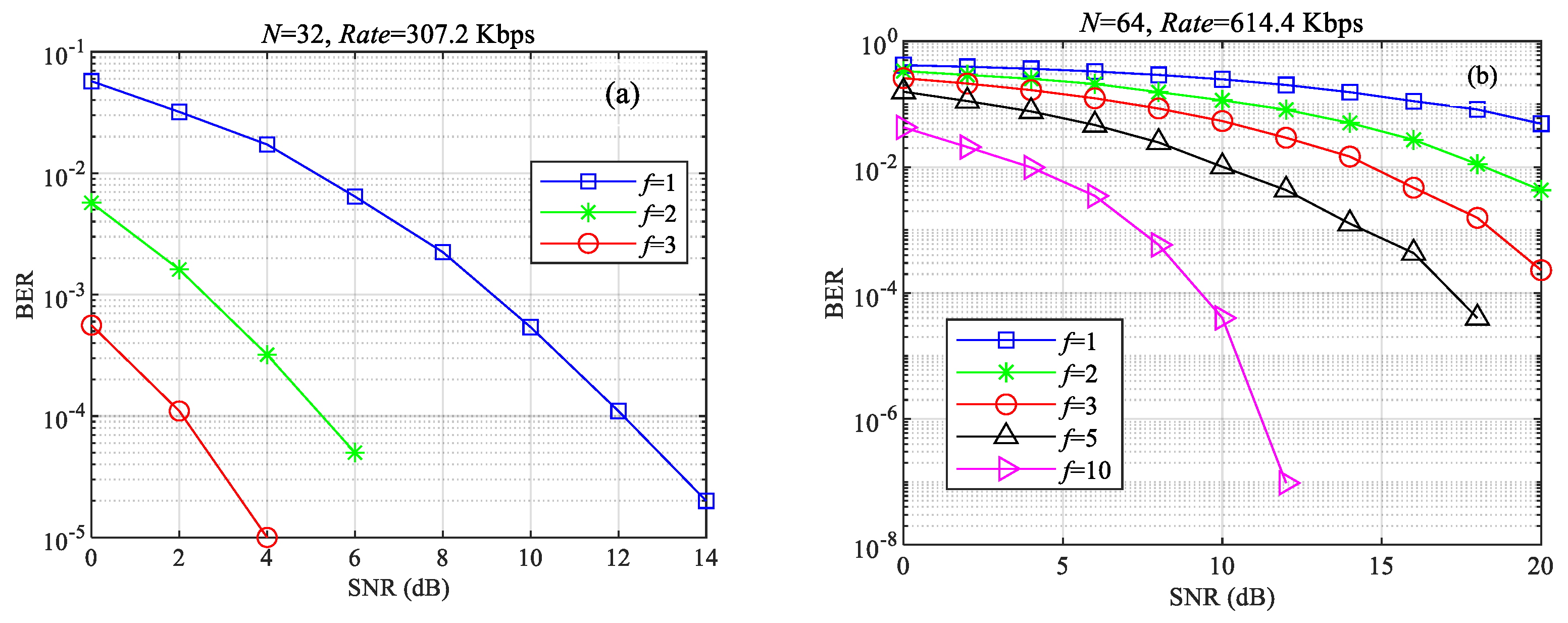
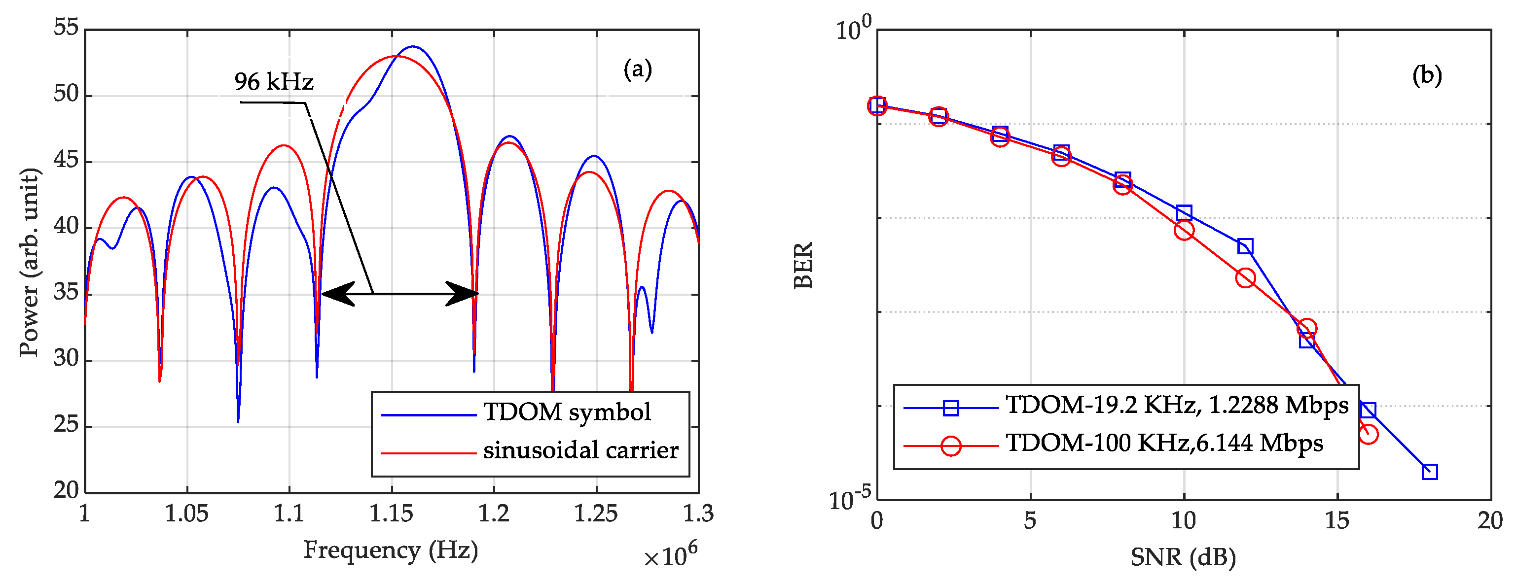
4.2. Peak Communication Rate When the Bandwidth of TDOM Is Nearly 100 KHz

In this subsection, we will discuss the peak communication rate that the TDOM can reach when it occupies a bandwidth close to that of the VDES, i.e., 100 KHz. When the bandwidth is increased from 19.2 KHz to nearly 100 KHz, the duration of the TDOM symbol must be decreased. In this subsection, we increase the symbol rate of the TDOM to 24,000 symbols/s. As a result, the bandwidth of the TDOM symbol is 96 KHz, as shown in Figure 9a.
The system performance under the maritime multipath channel is shown in Figure 9b. The total number of carriers is 128, and the frequency of the carrier f is 30. We can see that the TDOM system with a bandwidth of 96 KHz can achieve a performance which is similar that of to the TDOM system with a bandwidth of 19.2 KHz. The communication rate of the TDOM system now increases to
2 bit / carrier × 128 carrier / symbol × 24000 symbol / s = 6.144 Mbit / s .
Therefore, the communication rate of the TDOM system with a 96 KHz bandwidth can reach 20 times that of the VDES, as shown in Equation (27).
R a t e T D O M R a t e V D E S = 6.144 Mbps 307.2 Kbps = 20 .

4.3. Comparison Between TDOM and Other Maritime Communications

To demonstrate the superiority of the proposed TDOM technology, the comparison of the communication performance between TDOM system with the VDES is given in Figure 10. It can be seen that the communication performance of the sin-TDOM system with f = 20 and N = 32 is better than that of the VDES system, in which the TDOM system occupies 1/5 of the bandwidth of the VDES system. The communication performance of the sin-TDOM system with f = 30 and N = 96 is comparable to that of the VDES system, in which time the communication rate of the TDOM system is three times higher than the peak rate of the VDES system. In addition, when N = 128, the communication performance of the cos-TDOM systems with f = 10, 20 and 30 is comparable to that of the VDESs, with the peak communication rate of the TDOM system being 20 times that of the VDES, and the occupied bandwidth still being one-fifth of that of the VDES. Thus, the peak spectrum efficiency is 20 times that of the VDES. Therefore, the TDOM system simultaneously achieves a reduction in bandwidth and an increase in transmission rate with higher spectral efficiency, which will provide better support for the maritime communication network to provide better-quality services.

5. Conclusions

In this paper, a maritime communication system based on time-delay overlapping modulation with higher spectral efficiency and a higher communication rate is proposed. The system breaks through the strict orthogonality constraint of the carrier through a simple delay and through overlapping modulation at the transmitter to achieve high-spectral-efficiency non-orthogonal communication. It is shown that spectral efficiency of the TDOM system can be up to 20 times of that of a VDES in a bandwidth of less than 20 kHz, and its communication performance is comparable to that of the VDES. Meanwhile, when occupying the same bandwidth as the VDES, the peak communication rate of the TDOM system can reach up to 6.144 Mbps, which is 20 times that of the VDES. It is worth mentioning that, as a physical layer modulation technique, TDOM technology can be extended to any other communication scenario with high communication rate and spectral efficiency requirements. Future research will be conducted in the following areas. Firstly, similarly to maritime communication systems, the underwater communication also has an urgent need for high spectral efficiency and communication rates. Therefore, deploying TDOM technology in underwater communications is one of the future work directions. However, unlike the maritime multipath channels discussed in this paper, underwater communication channels are more complex. The severe Doppler effect is one of the forms of interferences in underwater communications. Therefore, it is necessary to investigate TDOM systems that can counteract the Doppler shift. In addition, future work should include reducing system complexity and combining the TDOM system with coding techniques to further enhance the communication performance and to advance the practicalization of TDOM.

Author Contributions

Simulation, T.M.; writing, X.D.; writing—review and editing, X.D.; supervision, X.D. and D.L. All authors have read and agreed to the published version of the manuscript.

Funding

This research was funded in part by the National Natural Science Foundation of China under Grant 62001077, and in part by the China Postdoctoral Science Foundation under Grant 2019M661075 and Grant 2022T150081.

Institutional Review Board Statement

Not applicable.

Informed Consent Statement

Not applicable.

Data Availability Statement

The data are unavailable due to privacy reasons.

Conflicts of Interest

The funders had no role in the design of the study; in the collection, analyses, or interpretation of data; in the writing of the manuscript; or in the decision to publish the results.

References

  1. Orabi, M.; Khalife, J.; Kassas, Z.M. Opportunistic navigation with doppler measurements from Iridium next and orbcomm LEO satellites. In Proceedings of the 2021 IEEE Aerospace Conference (50100), Big Sky, MT, USA, 6–13 March 2021. [Google Scholar]
  2. Surekha, T.P.; Ananthapadmanabha, T.; Puttamadappa, C. Performance evaluation of VSAT-QPSK system. Int. J. Emerg. Technol. Adv. Eng. 2013, 3, 726–730. [Google Scholar]
  3. Zhuang, Q.; Zheng, C. Research on INMARSAT based on Ka band and applications. In Proceedings of the 2017 4th International Conference on Information, Cybernetics and Computational Social Systems (ICCSS), Dalian, China, 24–26 July 2017; pp. 127–129. [Google Scholar]
  4. Koulikova, Y.; Roberti, L. Global Xpress Broadband. Available online: https://www.itu.int/dms_pub/itu-r/md/12/iturka.band/c/R12-ITURKA.BAND-C-0002!!PDF-E.pdf (accessed on 1 September 2012).
  5. ITU-R M.1084-5; Interim Solutions for Improved Efficiency in the Use of the Band 156–174 MHz by Stations in the Maritime Mobile Service. International Telecommunication Union: Geneva, Switzerland, 2012.
  6. ITU-R M.2092-0; Technical Characteristics for a VHF Data Exchange System in the VHF Maritime Mobile Band. International Telecommunication Union: Geneva, Switzerland, 2015.
  7. Zhou, M.-T.; Hoang, V.D.; Harada, H.; Pathmasuntharam, J.S.; Wang, H.; Kong, P.-Y.; Ang, C.-W.; Ge, Y.; Wen, S. TRITON: High-speed maritime wireless mesh network. IEEE Wirel. Commun. 2013, 20, 134–142. [Google Scholar] [CrossRef]
  8. Bekkadal, F.; Yang, K. Novel maritime communications technologies. In Proceedings of the 2010 10th Mediterranean Microwave Symposium (MMS), Ankara, Türkiye, 25–27 August 2010; pp. 338–341. [Google Scholar]
  9. Kim, Y.; Kim, J.; Wang, Y.; Chang, K.; Park, J.W.; Lim, Y. Application scenarios of nautical Ad-Hoc network for maritime communications. In Proceedings of the OCEANS 2009, Biloxi, MS, USA, 26–29 October 2009; pp. 1–4. [Google Scholar]
  10. Campos, R.; Oliveira, T.; Cruz, N.; Matos, A.; Almeida, J.M. BLUECOM+: Cost-effective broadband communications at remote ocean areas. In Proceedings of the OCEANS 2016, Shanghai, China, 10–13 April 2016. [Google Scholar]
  11. Teixeira, F.B.; Oliveira, T.; Lopes, M.; Leocadio, C.; Salazar, P.; Ruela, J.; Campos, R.; Ricardo, M. Enabling broadband internet access offshore using tethered balloons: The BLUECOM+ experience. In Proceedings of the OCEANS 2017, Aberdeen, UK, 19–22 June 2017. [Google Scholar]
  12. Lopes, M.J.; Teixeira, F.; Mamede, J.B.; Campos, R. Wi-Fi broadband maritime communications using 5.8 GHz band. In Proceedings of the 2014 Underwater Communications and Networking (UComms), Sestri Levante, Italy, 3–5 September 2014. [Google Scholar]
  13. Garroppo, R.G.; Giordano, S.; Iacono, D.; Cignoni, A.; Falzarano, M. WiMAX testbed for interconnection of mobile navy units in operational scenarios. In Proceedings of the MILCOM 2008—2008 IEEE Military Communications Conference, San Diego, CA, USA, 16–19 November 2008; p. 3907. [Google Scholar]
  14. Wang, J.; Zhou, H.; Li, Y.; Sun, Q.; Wu, Y.; Jin, S.; Quek, T.Q.S.; Xu, C. Wireless channel models for maritime communications. IEEE Access 2018, 6, 68070–68088. [Google Scholar] [CrossRef]
  15. Garroppo, R.G.; Giordano, S.; Iacono, D. Experimental and simulation study of a WiMAX system in the sea port scenario. In Proceedings of the 2009 IEEE International Conference on Communications, Dresden, Germany, 14–18 June 2009; pp. 4729–4733. [Google Scholar]
  16. Choi, M.S.; Park, S.; Lee, Y.; Lee, S.R. Ship to ship maritime communication for e-Navigation using WiMAX. Int. J. Multimed. Ubiquitous Eng. 2014, 9, 171–178. [Google Scholar] [CrossRef]
  17. Anwar, S.M.; Goron, E.; Toutain, Y.; Peronne, J.P.; Hethuin, S. LTE terminal for maritime applications. In Proceedings of the 2013 Military Communications and Information Systems Conference, Saint-Malo, France, 7–9 October 2013. [Google Scholar]
  18. Kim, H.-J.; Choi, J.-K.; Yoo, D.-S.; Jang, B.-T.; Chong, K.-T. Implementation of MariComm bridge for LTE-WLAN maritime heterogeneous relay network. In Proceedings of the 2015 17th International Conference on Advanced Communication Technology (ICACT), Pyeongchang, Republic of Korea, 1–3 July 2015; pp. 230–234. [Google Scholar]
  19. Xu, Y.; Jiang, S.; Liu, F. An LTE-based communication architecture for coastal networks. In Proceedings of the 11th International Conference on Underwater Networks & Systems (WUWNET ’16), Shanghai, China, 24–26 October 2016. [Google Scholar]
  20. ITU-R M.1842-1; Characteristics of VHF Radio Systems and Equipment for the Exchange of Data and Electronic Mail in the Maritime Mobile Service RR Appendix 18 Channels. International Telecommunication Union: Geneva, Switzerland, 2009.
  21. Liang, C.; Jin, Y.; Hu, Q. Multipath time delay in maritime VHF data exchange system. J. Shanghai Marit. Univ. 2016, 37, 55–58. [Google Scholar]
  22. Qu, F.; Li, Z.; Zhang, M.; Tu, X.; Wei, Y. A Carrier-Based Gardner Timing Synchronization Algorithm for BPSK Signal in Maritime Communication. J. Mar. Sci. Eng. 2023, 11, 829. [Google Scholar] [CrossRef]
  23. Huang, F.; Liao, X.; Bai, Y. Multipath channel model for radio propagation over sea surface. Wirel. Pers. Commun. 2016, 90, 245–257. [Google Scholar] [CrossRef]
Figure 1. Block diagram of the time-delay overlapping modulation.
Jmse 13 00345 g001
Figure 2. Schematic diagram of modulation principle of time-delay overlapping modulation system.
Jmse 13 00345 g002
Figure 3. Schematic diagram of the maritime communications channel model.
Jmse 13 00345 g003
Figure 4. Spectrum diagram of typical communication technologies.
Jmse 13 00345 g004
Figure 5. Communication performance and the spectrum of the TDOM system. (a) Communication performance under the AWGN channel. (b) The spectrum of a TDOM symbol.
Jmse 13 00345 g005
Figure 6. Communication performance of TDOM system under different carrier frequencies. (ad) The number of carriers, i.e., N = 32, 64, 96, and 128.
Jmse 13 00345 g006aJmse 13 00345 g006b
Figure 7. Communication performance of TDOM system under the maritime multipath channel. (a) f = 1, (b) f = 10, (c) f = 20, (d) f = 30.
Jmse 13 00345 g007
Figure 8. Communication performance of cosine TDOM system under the maritime multipath channel. The total number of carriers within one symbol is 128.
Jmse 13 00345 g008
Figure 9. Bandwidth and performance of the TDOM system with a bandwidth of 96 KHz. (a) The spectrum of the TDOM symbol, (b) communication performance of the TDOM with 19.2 KHz and nearly 100 KHz bandwidth.
Jmse 13 00345 g009
Figure 10. Performance comparison of TDOM systems with VDESs.
Jmse 13 00345 g010
Table 1. Magnitude mapping rules.
Ba
[0,0]−1.05
[0,1]−0.35
[1,1]0.35
[1,0]1.05
Table 2. Norm of the matrix R−1 for different carrier numbers.
N R 1
320.0489
640.3967
961.3427
1283.1839
Table 3. Norm of the matrix R−1 at different carrier frequencies.
N & f R 1
f = 10.0489
f = 20.0119
32f = 30.0051
f = 50.0016
f = 101.8127 × 10⁻⁴
f = 10.3967
f = 20.0986
64f = 30.0434
f = 50.0151
f = 100.0032
f = 11.3427
f = 20.3348
96f = 30.1482
f = 50.0526
f = 100.0123
f = 13.1839
f = 20.7948
128f = 30.3524
f = 50.1259
f = 100.0903
Table 4. Norm of the matrix R−1 for sine–carrier and cosine–carrier TDOM systems. The total number of carriers within one symbol is 128.
fCarrier Form R 1
1sine3.1839
20cosine0.0019
30cosine0.0018
Disclaimer/Publisher’s Note: The statements, opinions and data contained in all publications are solely those of the individual author(s) and contributor(s) and not of MDPI and/or the editor(s). MDPI and/or the editor(s) disclaim responsibility for any injury to people or property resulting from any ideas, methods, instructions or products referred to in the content.

