Article

Layer-by-Layer Self-Assembly Marine Antifouling Coating of Phenol Absorbed by Polyvinylpyrrolidone Anchored on Stainless Steel Surfaces

1
School of Mechanical Engineering, Yangzhou University, Yangzhou 225009, China
2
Jiangsu Key Laboratory of Surface Strengthening and Functional Manufacturing, Yangzhou University, Yangzhou 225009, China
*
Authors to whom correspondence should be addressed.
J. Mar. Sci. Eng. 2025, 13(3), 568; https://doi.org/10.3390/jmse13030568
Submission received: 19 February 2025 / Revised: 11 March 2025 / Accepted: 12 March 2025 / Published: 14 March 2025
(This article belongs to the Section Ocean Engineering)

Abstract

:
Marine biofouling is a major problem that contributes to the failure of man-made marine structures. Conventional marine antifouling coatings that release heavy metal ions for antimicrobial purposes are no longer in line with today’s environmental issues. In this paper, a layer-by-layer (LBL) self-assembled marine antifouling coating based on an addition reaction between polyvinylpyrrolidone (PVP) and phenols to anchor pyrogallic (PG) with an antimicrobial effect on stainless steel surfaces is presented. For this purpose, three phenolics were selected, and their antifouling effects were compared. Field emission scanning electron microscopy, contact angle measurement, X-ray photoelectron spectroscopy (XPS) and Fourier transform infrared spectroscopy analysis (FTIR) were used to thoroughly characterize the LBLPGs, and the results showed superior homogeneity of the coatings with no significant delamination. Simulated marine antifouling and friction tests showed that the coating inhibited Staphylococcus aureus (S. aureus), Escherichia coli (E. coli), and Phaeodactylum tricornutum (P. tricornutum) by more than 90% and reduced the friction coefficient of the stainless steel surface from 0.38 to 0.24, demonstrating superior antifouling and friction resistance effects.

1. Introduction

Marine biofouling is characterized by the attachment and proliferation of microorganisms, algae, invertebrates, and various other organisms on the surfaces of ships, underwater installations, and marine equipment within marine settings [1,2,3]. This occurrence has the capacity to augment the resistance that ships face during navigation, thereby causing an elevation in fuel consumption. Moreover, it is capable of impairing the structural integrity of the ship hull and associated equipment. By hastening the corrosion process, it drives up both maintenance and operational expenses. As estimated in [4,5], the annual economic losses stemming from biofouling amount to millions of dollars. In addition, the generation of acidic gases like sulfur dioxide and carbon dioxide from fuel combustion can intensify ocean acidification, exerting a severe influence on the marine environment [6]. Furthermore, biofouling may also trigger the cross-regional invasion of species, which can exert detrimental effects on the local ecosystem [7].
The application of biocide-infused antifouling paints onto artificial surfaces in contact with seawater remains one of the most prevalent strategies for mitigating marine biofouling [8]. During the 1960s, tributyltin (TBT) compounds were incorporated into antifouling paints, signifying a notable breakthrough in antifouling paint technology [9]. TBT-based paints showcased outstanding antifouling capabilities and an extended shelf life. However, numerous studies have evidenced that TBT poses a high level of toxicity to marine organisms, which subsequently led to its gradual global ban. In 2008, the International Maritime Organization (IMO) officially prohibited the utilization of TBT-containing antifouling paints [10]. Moreover, the currently widely employed copper-based antifouling coatings are under further scrutiny to determine their appropriateness, as the release of copper ions has been found to be toxic to mammals [2,11]. In summary, the development of more eco-friendly marine antifouling coatings emerges as a promising trajectory within the industry.
In recent years, layer-by-layer deposition technology has garnered significant attention due to its remarkable capability of precisely regulating the film thickness. Through the alternate deposition of charged or functionalized polymer layers, LBL technology enables the construction of nanoscale multilayer architectures, thereby achieving specific functionalities. For instance, Yu et al. synthesized amphiphilic polysaccharides by conjugating hydrophobic pentafluoropropylamine (PFPA) to the carboxylic acid groups of hydrophilic alginates, which are natural biopolymers with high water-binding capacity. The fabricated coating exhibited notable resistance against marine fouling organisms and proteins [12]. Xu et al. utilized host–guest interaction chemistry to develop a low-fouling, antimicrobial, and antibiocorrosion multilayer coating on stainless steel via LBL deposition of polyethylenimine-β-cyclodextrin (PEI-β-CD) and ferrocene-modified chitosan (Fc-CHT) [13]. Li et al. initially coated the surface with a layer of poly-dopamine (PDA) to safeguard against corrosion. Subsequently, a monolayer of 3-aminopropyltriethoxysilane (APTES) was self-assembled, which not only further enhanced the anticorrosion performance but also improved the grafting efficiency. Thereafter, an LBL coating was prepared by immobilizing a zwitterionic polysulfobetaine (PSB) polymer brush layer, and the surface effectively repelled biological fouling [14]. Zhao et al. emulated the surface microstructure of kelp and carried out chemical modification on the surface of the isotropic microstructure of the PDMS replica through layer-by-layer assembly. They chemically modified the surface with a polyelectrolyte layer consisting of sodium alginate and guanidine-hexamethylenediamine PEI (poly (GHPEI)) [15]. The outcomes of the antifouling experiments revealed that the coating possessed excellent antibacterial and antifouling properties.
PVP is a linear polymer composed of 1-vinyl-2-pyrrolidone monomers. Prior research has demonstrated that it exhibits negligible developmental toxicity towards organisms. PVP finds extensive applications in adhesives, emulsion stabilizers, and film formers [16]. Investigations have revealed that PVP exerts a binding and absorption effect on phenolic compounds, thus enabling the adsorption process [17]. Previous studies have indicated that the hydrogel-like substance formed from the combination of PVP and tannic acid possesses a robust cohesive strength, measuring 3.71 MPa, which is 44 times greater than that of conventional PVP [18]. Catechins and polyphenols are abundant in nature. Upon oxidation, they generate reactive oxygen species (ROS) as by-products, which have been evidenced to function as an effective and broad-spectrum antimicrobial agent in numerous industrial and biomedical applications [19,20,21]. Polyethyleneimine (PEI) is a water-soluble polyamine, and the NH- groups on its side chain can interact strongly with phenol via hydrogen bonding, facilitating the adsorption of phenol [22]. Wong et al. demonstrated that phenol/amine adhesives prepared with PEI, phenol, and SiO2 can attain a bond strength of 5.4 MPa, comparable to that of a commercial 3 M epoxy adhesive. These adhesives also exhibit excellent biocompatibility, rendering them suitable for use as medical adhesives for wound closure and fracture repair, as well as for diverse applications in both domestic and industrial settings [23].
In the present investigation, we first examined and determined that among the three phenolic compounds, namely propyl gallate (PG), catechol (PC), and dopamine (DA), PG displayed the most potent and extensive antibacterial activity. Subsequently, based on the adsorption principle of phenolic substances by PVP, PG was anchored layer by layer onto the surface of 304 stainless steel. Following that, the composition, antifouling performance, frictional characteristics, and mechanical properties of the coating were thoroughly characterized. The findings revealed that the SS-PG@PVP/PEI coating fabricated in this study exhibited strong adhesion, along with excellent antifouling and drag-reducing effects. This offers a novel material alternative for the development of LBL self-assembled antifouling coatings.

2. Materials and Methods

2.1. Materials

DA, propidium iodide (PI), and glutaraldehyde were purchased from Aladdin Biochemical Technology Co., Ltd. (Shanghai, China). PG, PC, and PEI (99%, 1800 MW) were purchased from Macklin Biochemical Technology Co., Ltd. (Shanghai, China). PVP (K90) and ethanol (>99.7%) were purchased from Sinopharm Chemical Reagent Co., Ltd. (Shanghai, China). LB broth culture medium and LB agar culture medium were purchased from Shanghai Bio-way technology Co., Ltd. (Shanghai, China). The BG11 culture medium was purchased from Qingdao Hope Bio-technology Co., Ltd. (Shandong, China). The above reagents were of analytical grade and used without further purification.

2.2. Fabrication of Layer-by-Layer (LbL)-Deposited Multilayer Coatings

A 304 stainless steel (SS 304) substrate with dimensions of 10 mm × 10 mm × 1 mm was activated in a piranha solution (prepared from 70% concentrated sulfuric acid and 30% hydrogen peroxide with a concentration of 30 vol%) for 4 h and then successively cleaned with deionized water, acetone, and ethanol under ultrasonic conditions. The resulting surface of the SS substrate, which is rich in hydroxyl groups, is referred to as the original SS surface. A PVP solution was prepared at a concentration of 50 mg/mL. The initial SS substrate was placed in a 36-well plate, 1 mL of PVP solution was added, and the plate was allowed to sit for 1 h. A PG solution with a concentration of 0.5 M was then prepared. The PVP solution was removed, and 1 mL of PG solution was added. The plate was placed horizontally in a shaker and rotated to anchor the PG to the stainless steel surface. The remaining liquid was then removed, and the PG that was not anchored to the surface was rinsed with deionized water. The above process was repeated to allow each layer of PG to undergo a condensation reaction with PVP to obtain a layer-by-layer self-assembled SS-PG@PVP coating. The PVP/PEI solution was obtained by adding 5 vol% PEI to the above PVP solution, and the SS-PG@PVP/PEI layer-by-layer self-assembled coating formed by the condensation reaction of PG-PVP-PEI was obtained by the same process (Figure 1). In the preparation of the corresponding coating, the method involves the application of the coating in three separate stages. Subsequent to each such application, the coating is permitted to undergo air-drying at a temperature of 25 °C for a period of 4 h prior to the subsequent application.

2.3. Basic Characterization

The surface’s three-dimensional morphology, both before and after the hydrogel film swell, was observed using a Keyence 3D Laser Scanning Microscope (VK-X1000, Keyence Corp., Osaka, Japan). In addition, the contact angle of pure water on the sample surface was measured using a Contact Angle Measuring Instrument (JC2000D, Shanghai Zhongchen Digital Technology Equipment Co., Ltd., Shanghai, China), and the average value of three different positions on the sample surface was obtained. An S-4800 field emission scanning electron microscope (SEM; Hitachi Instruments, Inc., Tokyo, Japan) was utilized to collect the surface morphology of coated specimens.
The undried coating was peeled off and gathered, placed in a vacuum freeze-drying oven for 24 h, and then placed in a vacuum drying oven to dry to a constant weight. After being ground evenly with KBr, it was made into a tablet. A Cary 610/670 Fourier transform infrared spectrometer (FT-IR; Agilent Technologies, Inc., Santa Clara, CA, USA) was used to perform 128 scans in the range of 4000 to 400 cm−1, with a resolution of 4 cm−1 and an average of 64 scans, to collect information on the surface functional groups of the sample. In addition, X-ray photoelectron spectroscopy (XPS) analysis of the coating surface was performed using an ESCALAB 250Xi instrument (Thermo Fisher Scientific Inc., Pittsburgh, PA, USA).

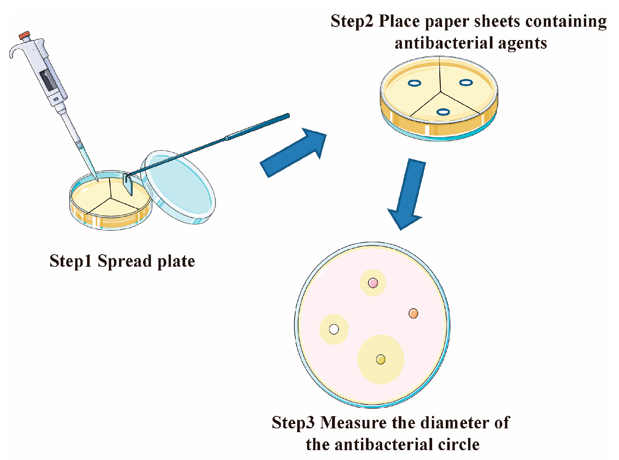
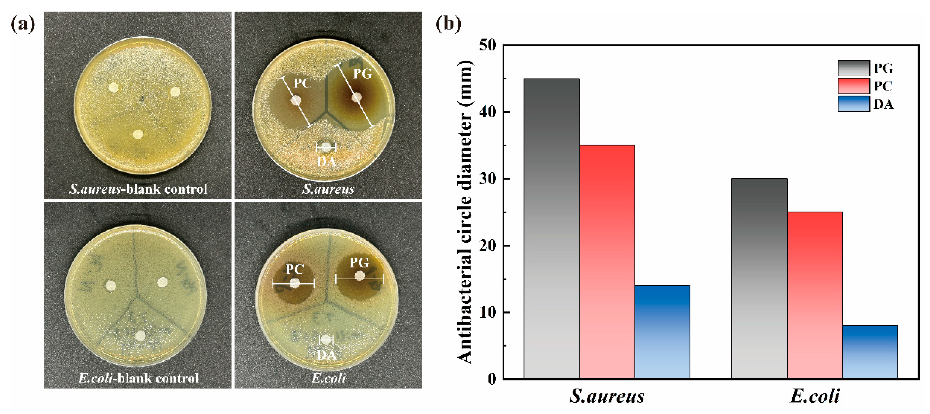
2.4. Antifouling Performance Test

The antibacterial activity of the selected antifouling agent was tested using the paper disc method (Figure 2). Filter paper discs with a diameter of 6 mm were prepared, autoclaved, and dried on a clean bench. The selected antifouling agent was dissolved in autoclaved deionized water to a concentration of 50 mg/mL, and 100 μL was pipetted onto the filter paper discs. LB agar medium was prepared and divided into several parts. After the inoculation of the bacterial suspension, the filter paper with the antifouling agent was placed in each part. For each experiment, a blank control group was prepared with sterile deionized water. The medium was placed in a 37 °C incubator for 24 h.
The antibacterial properties of the surfaces were tested using the typical Gram-positive bacterium S. aureus and the typical Gram-negative bacterium E. coli. The anti-algae properties of the surfaces were tested using a diatom, P. tricornutum. S. aureus and E. coli were cultured in LB broth medium, and P. tricornutum was cultured in artificial seawater (3.0% NaCl solution) containing BG11 medium. For the antibacterial test, the original and coated samples were placed in a 36-well plate, 1 mL of bacterial suspension was added to each well, and the samples were incubated at 37 °C in a constant-temperature incubator for 24 h. The samples were then rinsed with PBS to remove loosely adhering bacteria and immersed in 2. 5% glutaraldehyde solution at 4 °C for 6 h. The samples were then stained with PI solution at a concentration of 50 μg/mL in the dark, and the bacterial adhesion morphology on the sample surface was observed using a TCS SP8 STED (CLSM; Leica Microsystems GmbH, Wetzlar, Germany) confocal laser microscope. For the anti-algae adhesion experiment, the samples were immersed in the corresponding liquid medium in the light incubator together with the above algae and then removed after 7 days of immersion in a 12 h/12 h day and night environment at 25 °C. The algae with poor surface adhesion were rinsed with sterile artificial seawater (3.0% NaCl solution) for 3 min. The collected rinsed samples were fixed in 2.5% glutaraldehyde for 4 h at 4 °C in a refrigerator to fix the surface algae and then observed under a laser confocal microscope.
The adhesion rate was quantitatively analyzed using ImageJ software (v1.5.4) and calculated using the equation [24]
A R % = A A × 100 %
where AR% denotes the attachment rate, A′ the area of microbial attachment, and A the total area of the field of view.

2.5. Characterization of Lubricating Properties

The original SS surface was embedded in epoxy and allowed to cure. After curing, the surface was polished until it was exposed. The exposed surface was coated according to the method described in Section 2.2 to obtain a friction test specimen. The specimens were subjected to friction in the Tribostudio tribometer (Yangzhou University, China) under dry and artificial seawater immersion conditions [25]. The specimens were made of GCr15 high-carbon chromium-bearing steel; the friction frequency was 2 Hz, the normal pressure was 2 N, and the friction and wear test was performed for 10 min to obtain the average friction coefficient of each sample surface.

2.6. Micro-Scratch Test

The LbL-deposited multilayer coatings were tested for mechanical stability after swelling by a micro-scratch test (MST) using Anton Paar’s CSM RST Large Load Scratch Tester (Anton Paar GbmH, Graz, Austria) with a spherical indenter (r = 500 μm); the test parameters are shown in Table 1.
According to Hertz’s theory, the contact area of the spherical indenter with the stylus follows a semi-elliptical shape, at which point the contact pressure pm is calculated using the following equation [26]:
p m = 2 3 6 L c E r 2 π 3 R 2 1 3
where Lc is the critical normal force when the coating is destroyed, R is the radius of the spherical indenter, and Er is the discounted modulus of elasticity, which is used to characterize the effect of the non-rigid indenter on the load displacement and is introduced by Poisson’s ratio calculated by the following equation [27]
1 E r = 1 ν 2 E + 1 ν i 2 E i
where E and ν are Young’s modulus and Poisson ratio for the specimen and Ei and νi are the same parameters for the indenter. In this scratch test, the indenter material was diamond, and the sample substrate was 304 stainless steel; the values of Young’s modulus and Poisson’s ratio are taken from Table 2.

3. Results and Discussion

3.1. Basic Characterization

3.1.1. FT-IR and XPS Characterization

Fourier transform infrared spectroscopy (FT-IR) using KBr pressed tablets was used to collect information on the functional groups on the surface of the two coatings (Figure 3a). The broad peak at 3440 cm−1 for the SS-PG@PVP and SS-PG@PVP/PEI coatings is due to the large number of -OH functional groups from the PG and PVP molecules that are bound together during the self-assembly of the coating. For the SS-PG@PVP/PEI coating, the peak at 3250 cm−1 broadens further to 3268 cm−1, which is due to the addition of PEI, which introduces N-H groups into the coating. The peak at 1612 cm−1 also supports this view. A strong and broad absorption band between 3000 and 2800 cm−1, which is caused by asymmetric and symmetric stretching vibrations of the NH3+ group, indicates the formation of ammonium salts.
XPS was used to further analyze the elemental information on the surface of the sample. The quantitative analysis data obtained from the wide scan in Figure 3b are shown in Table 3, and the results confirm that both SS-PG@PVP and SS-PG@PVP/PEI coatings consist mainly of C, N, and O elements. After the addition of PEI, the N component on the surface of the sample increased from 9.57% to 10.77%, O increased to 43.48%, and the content of the C component in the system decreased to 45.75%. It is worth noting that the iron content on the surface of the sample is almost undetectable, indicating that the PVP-assisted film is dense and forms a protective layer on the SS surface. The spectra were calibrated using the C-C peak at 284.8 eV to obtain the C1s, N1s, and O1s high-resolution spectra of SS-PG@PVP and SS-PG@PVP/PEI (Figure 3c–h). Without the addition of PEI, the spectral peak splitting treatment of C1s on the sample surface yielded peaks at 287.3 and 284.8 eV attributed to C=N and C-C, respectively, and with the introduction of PEI, the peaks at 285.5 and 283.8 eV appeared for the C-N and C=C functional groups, respectively. In the N1s spectra of both samples, the peak at 399.3 eV appeared as pyrrolic N attributed to PVP, and with the addition of PEI, C-NH2 (400.8 eV) appeared in SS-PG@PVP/PEI [30]. In addition, the peaks appearing at 531.6 and 530.48 eV in the O1s spectra were attributed to the formation of C=O functional groups by PVP and PEI binding PG, respectively.

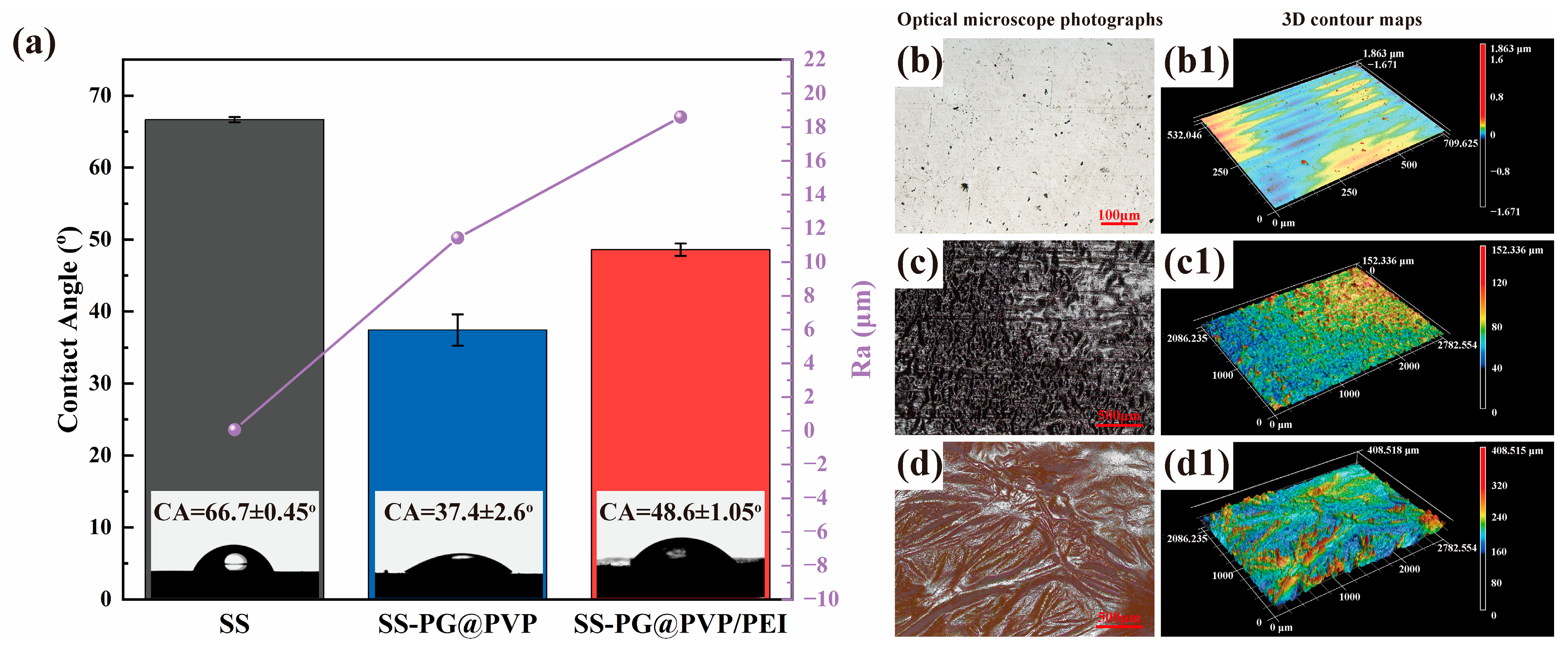
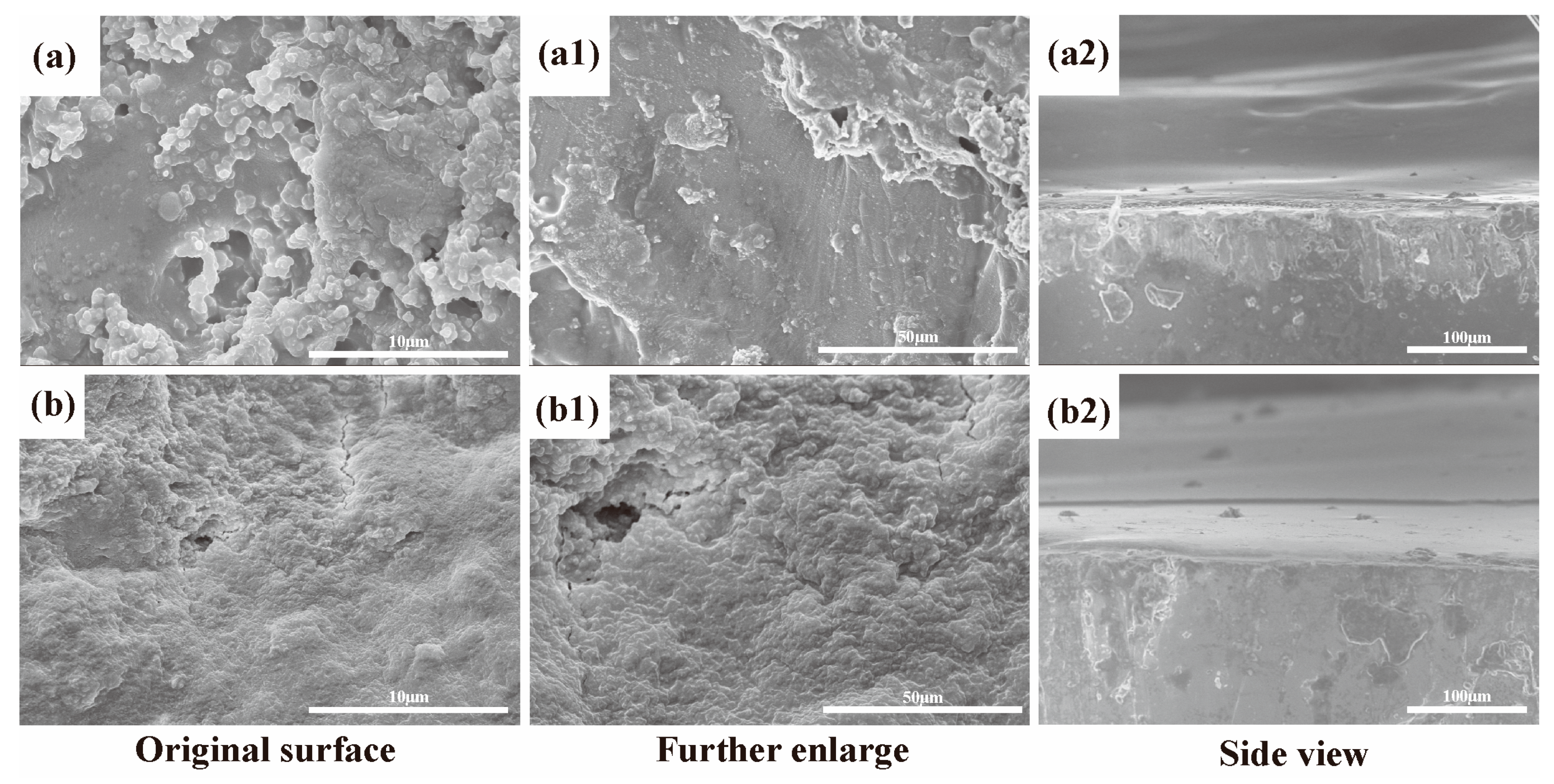
3.1.2. Morphological Characterization

The water contact angle of the sample surface corresponded to its wettability [31,32]. The CA of the initial SS surface at room temperature was 66.7 ± 0.45°, which decreased to 37.4 ± 2.6° after the layer-by-layer deposition of the PG@PVP coating, which was attributed to the fact that PG, a hydroxyl-rich compound, exhibited hydrophilicity in the coating formed after anchoring to the PVP surface (Figure 4a). After the addition of PEI, the CA of the coated surface increased to 48.6 ± 1.05°, which was attributed to the NH group in the PEI binding to the C- in the PG, introducing a large number of hydrophobic sites into the coating surface [33].
The 3D contour maps of the sample surfaces were further analyzed to investigate the reasons for the changes in the contact angle of the coated surfaces (Figure 4(b–d,b1–d1)). The wavy three-dimensional structure on the pristine SS surface was created by processing, and after the PG@PVP coating was deposited, the surface exhibited a large rapier-like shape; the multilinear surface roughness was quantitatively analyzed, and the surface roughness Ra was increased from 0.062 μm to 11.43 μm. For the same material, the increase in surface roughness means that the water droplets have to overcome a greater force to penetrate and spread further, resulting in a larger contact angle. On the contrary, the decrease in surface CA of the SS-PG@PVP coating is further evidence that the coating surface contains a large number of hydrophilic groups. When the PVP molecular brushes anchoring the PG were replaced with PVP/PEI composite molecular brushes, the sample surfaces exhibited multiple wrinkled surfaces, and the Ra was further increased to 18.6 μm, suggesting that the increase in CA was a result of the hydrophobic groups combined with the increased surface roughness [34].
SEM was used to further analyze the sample surface. Figure 5(a1) shows a high-magnification SEM image of the surface morphology of the SS-PG@PVP sample. The image shows a coating with nodular protrusions, indicating a uniform deposition of the PVP layer. The surface exhibits a highly irregular morphology with a few defects, indicating a weak consistency in the application of the coating material. The layer appears continuous and well-bonded, highlighting the effective encapsulation of the substrate by the PVP coating. Figure 5(b1) shows an enlarged SEM image of the surface morphology of the SS-PG@PVP/PEI sample. This image shows a more homogeneous surface structure than the SS-PG@PVP. The presence of PEI introduces a smoother topography, with the nodules and irregularities of Figure 5a disappearing and being replaced by a rough and flat surface. This indicates an increase in the uniformity of the coating. Figure 5(a2,b2) provide side views of the SS-PG@PVP and SS-PG@PVP/PEI samples, respectively. The coating, which has undergone multiple self-assemblies, shows no delamination, indicating good integration between the layers of the material and strong adhesion and compatibility with the SS surface.

3.2. Antifouling Performance

The purpose of this work is to anchor antifouling agents on the PVP substrate to form a coating that has antifouling and drag reduction effects. Since PVP undergoes an addition reaction with catechins, three catechins, PG, PC, and DA, were selected for the paper disc method. The antibacterial effect of the three drugs was quantitatively analyzed by measuring the diameter of the antibacterial ring formed by coating a plate with an equal concentration of bacterial suspension and placing a filter paper disc containing the same concentration of the three drugs. The results of the solid medium after the above process were placed in a constant temperature incubator for sufficient growth, as shown in Figure 6a, and the results of quantitative analysis are shown in Figure 6b. For S. aureus and E. coli, PG showed a strong inhibitory effect, with the diameter of the inhibition zone formed being 45 mm and 30 mm, respectively. DA showed the weakest inhibitory effect, with the diameter of the inhibition zone being 14 mm and 8 mm, respectively. In summary, choosing PG as a biocide will achieve better results.
The colonization of marine fouling organisms (bacteria, algae, etc.) on the surface of marine equipment will directly lead to the occurrence of marine biofouling [21]. Bacteria adhering to the surface of the samples were inactivated and stained with PI after incubation in a liquid medium containing bacteria and rinsing several times, and the microbial adhesion on the surface of the samples was observed by confocal laser microscopy as shown in Figure 7 (PI staining was not necessary because algae would excite with a green fluorescence without staining). After adequate rinsing and inactivation, the fluorescence observed on the coated surface under CLSM was all fouling organisms colonizing the sample surface. The results of quantitative analysis of fluorescence intensity using ImageJ software are shown in Figure 8. The results of CLSM on the coated surface showed that PG anchored to the PVP surface had a better inhibitory effect on S. aureus, as evidenced by a significant reduction in fluorescence intensity, but the inhibitory effect was significantly weaker than that of PG@PVP/PEI for E. coli and P. tricornutum. Previous studies have shown that PG has an excellent inhibitory effect on S. aureus, with a minimal inhibitory concentration (MIC) of only 512 μg/mL, which is in agreement with the results obtained in this work [35].
SS-PG@PVP and SS-PG@PVP/PEI inhibited the selected target fouling organisms S. aureus, E. coli, and P. tricornutum by 89.14%, 62.33%, and 82.13% and 93.10%, 93.53%, and 95.40%, respectively. This is due to the fact that PG is a compound that produces a killing effect on microorganisms at very low concentrations, and this killing effect is retained when PG is combined with PVP to produce polyphenols. In addition, several studies have shown that PG has a promising application as a group sensing inhibitor (QSI); e.g., Ni et al. found that PG has an interfering effect on the secretion and sensing of Vibrio harveyi intermediary autoinducer (AI) molecules [36]. The killing effect of the samples against the three target microorganisms was further enhanced by the addition of PEI, which was attributed to its synergistic effect with PG after quaternization, and the antifouling effect was achieved by disrupting the electrostatic interactions of microbial cell membranes. The addition of PEI resulted in a significant increase in the antagonistic effect of the coating on the growth of Gram-negative E. coli, which was attributed to the synergistic increase in antifouling effect due to the ability of PEI to allow normally impermeable solutes to pass through the outer membrane (OM) of the Gram-negative bacteria [37]. Compared with current commercial copper-based antifouling agents, the self-assembled coatings do not contain heavy metal particles, which will not cause potential pollution to the marine environment. While biofouling manifestations are typically more pronounced in marine environments compared to freshwater systems, the encouraging outcomes from antifouling experiments conducted under simulated marine conditions indicate the coating’s efficacy in freshwater scenarios. Although this study focuses on maritime applications, the demonstrated antifouling mechanism may extend to freshwater vessels, expanding the coating’s applicability beyond traditional seawater domains.

3.3. Slippery Behavior

The objective of friction tests is to evaluate the wear resistance of coatings. A lower coefficient of friction is indicative of a higher wear resistance of the coating [38]. The average COF of the SS surface in dry friction was 0.50, and the dry friction coefficient increased to 0.71 after the PG@PVP coating was deposited (Figure 9). Following the incorporation of PEI, a slight decline in the friction coefficient to 0.66 was observed, attributable to the coating’s residual viscosity after drying, which resulted in a texturing effect on the upper sample. Furthermore, it was observed that the COF of SS immersed in seawater exhibited a gradual upward trend, which was attributed to the smooth surface of SS and its inability to retain water. The COF of the SS-PG@PVP coating surface exhibited a downward trend prior to 50 s, subsequently increasing gradually to 0.3. Following the incorporation of PEI, a decline in the COF was observed, which then stabilized. The mean COF of the three surfaces was determined to be 0.38, 0.27, and 0.24, as presented in Table 4. The experimental findings demonstrate that PEI significantly reduces the friction coefficient of the SS coating, indicating that the coating has become smoother, with excellent antifriction properties. Moreover, combined with the experimental results regarding PEI incorporation to enhance surface smoothness, a lower friction coefficient and surface uniformity were achieved, thereby reducing the resistance of seawater to the ship’s surface and ultimately decreasing energy consumption and greenhouse gas emissions [39]. It is noteworthy that the incorporation of PEI not only enhances the smoothness of the coating surface, but also improves its wear resistance, thereby extending the service life of the coating. This phenomenon can be attributed to the hydrophilicity of PEI, which forms a denser hydration layer on the surface, effectively filling and repairing small defects on the coating surface, reducing the friction contact area, and thereby reducing the friction coefficient [40].

3.4. Scratch Testing Results

The bond strength between the substrate and coating is a parameter that determines the durability and performance of the coating due to the positive correlation between the bond strength and force required to peel the coating [41]. To evaluate the bond strength of SS-PG@PVP and SS-PG@PVP/PEI coatings on SS surfaces, a series of micron scratch tests were performed. The critical load (Lc) referred to the normal force corresponding to the failure of the coating [42].
The results of scratching experiments on the three coatings showed that they had similar scratching behaviors; when the indenter was in contact with the coating and did not scratch through the coating, the AE signals were almost unchanged due to the lower modulus of the hydrogel coating itself, while the AE signal began to gradually increase when the indenter started to scratch through the coating, and when the indenter completely stripped the coating, the intense friction with the substrate caused fluctuations in the AE signals (Figure 10a,b). In the event of an abrupt alteration in the AE signal, it is postulated that the coating has been scratched through, and the standard pressure FN at this juncture is designated as Pm. The substitution of Pm at this moment into Formula 2 allows for the calculation of SS-PG@PVP. The adhesion of the coating is 1.61 MPa, but after chemical crosslinking with PEI, it increases to 2.02 MPa. Furthermore, the indentation depth of the coating, measured before and after the crosslinking of PEI, can serve as an indicator for assessing the coating’s thickness. The obtained values were 12.650 μm and 12.670 μm, respectively. These results indicate that, although the adhesion was improved by PEI, there was no substantial increase in the coating thickness. The thickness of the two single-sprayed LBL coatings was determined to be 4.22 ± 0.03 μm.

4. Conclusions

In this study, a new environmentally friendly antifouling coating based on the addition reaction between PVP and catechol to anchor phenolic substances with microbial inhibitory activity on stainless steel for marine antifouling purposes was proposed. The performance of the coating was tested in a simulated marine environment, and the experimental results are as follows:
(1)
The three catechins PG, PC, and DA with the strongest antibacterial effect were selected for anchoring on the SS surface by the paper disc method. The results showed that PG had the strongest inhibitory effect on both the selected Gram-negative and Gram-positive bacteria.
(2)
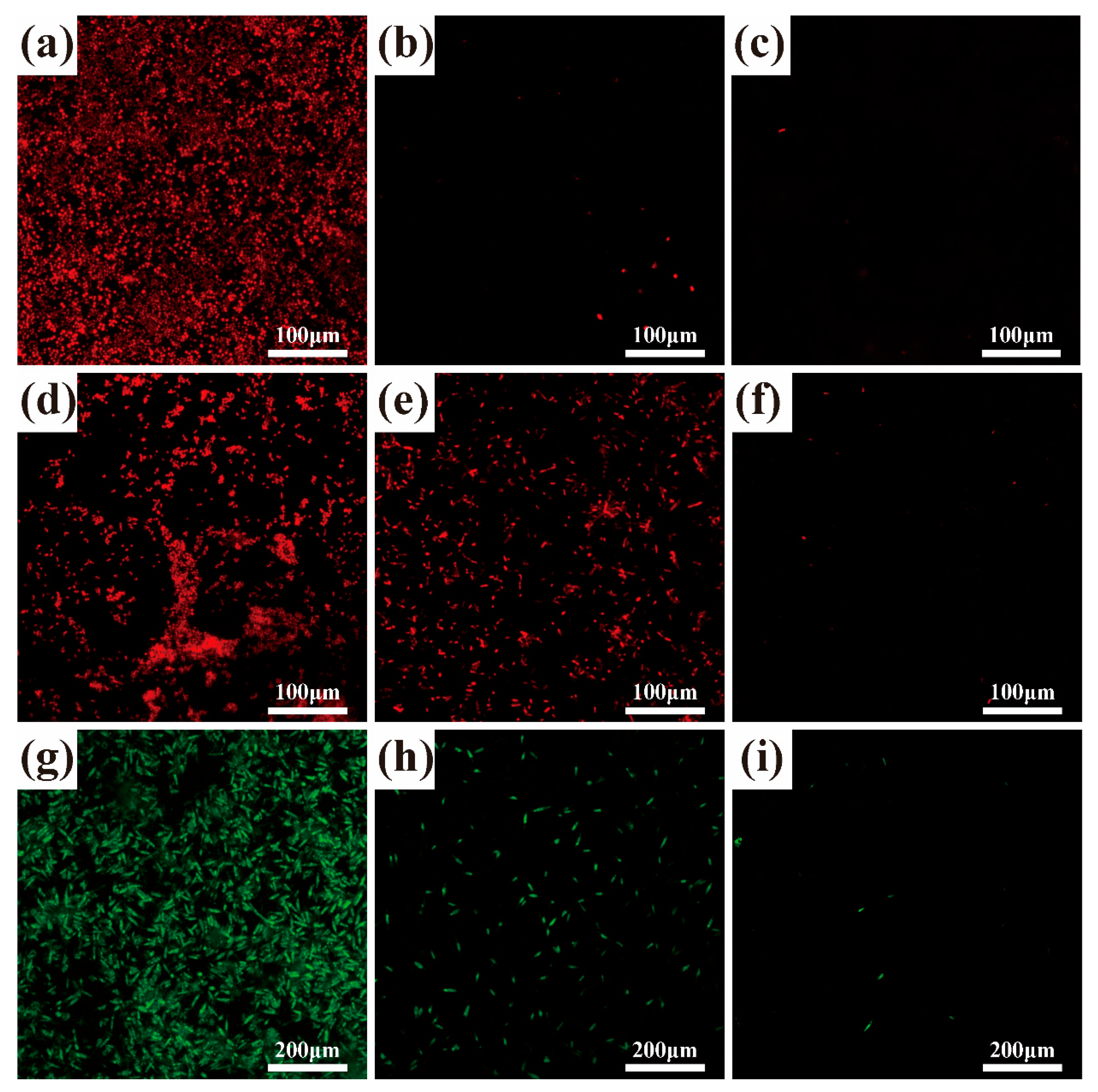
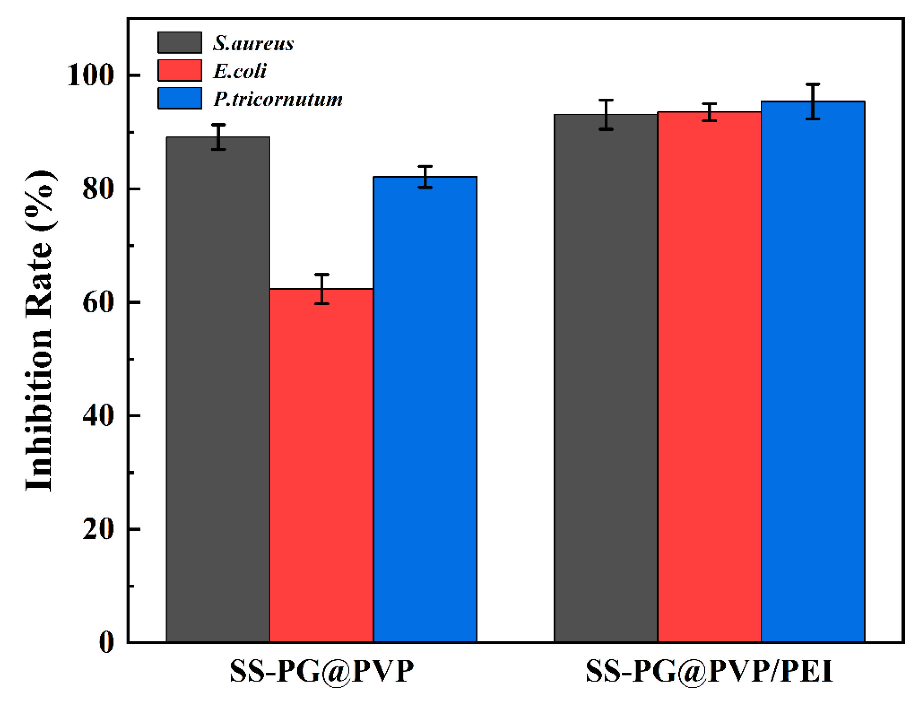
For the three common marine fouling organisms, S. aureus, E. coli, and P. tricornutum, the SS-PG@PVP coating has an inhibition rate of 89.14%, 62.33%, and 82.13%, respectively. The introduction of PEI further improves the antifouling effect, and the inhibition rates are increased to 93.10%, 93.53%, and 95.40%, respectively.
(3)
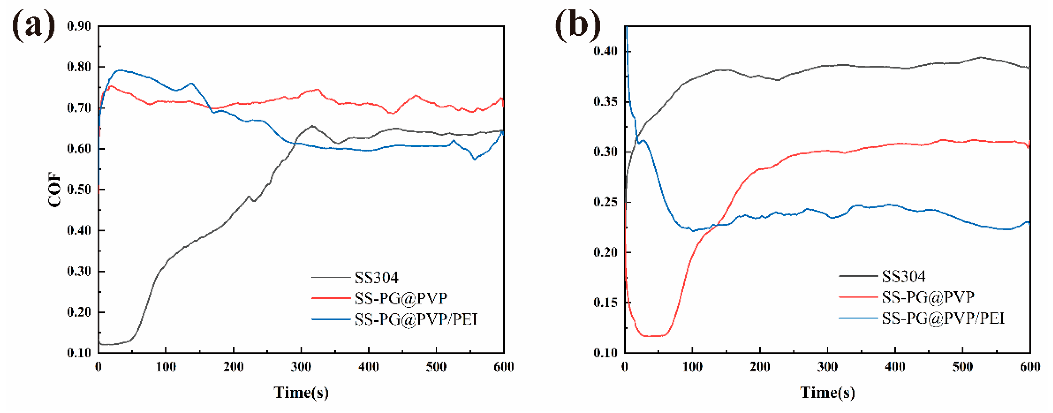
The SS-PG@PVP coating and SS-PG@PVP/PEI coating both have a lower coefficient of friction under seawater immersion, 0.27 and 0.24, respectively, which is lower than the bare SS substrate under seawater immersion (0.38).
(4)
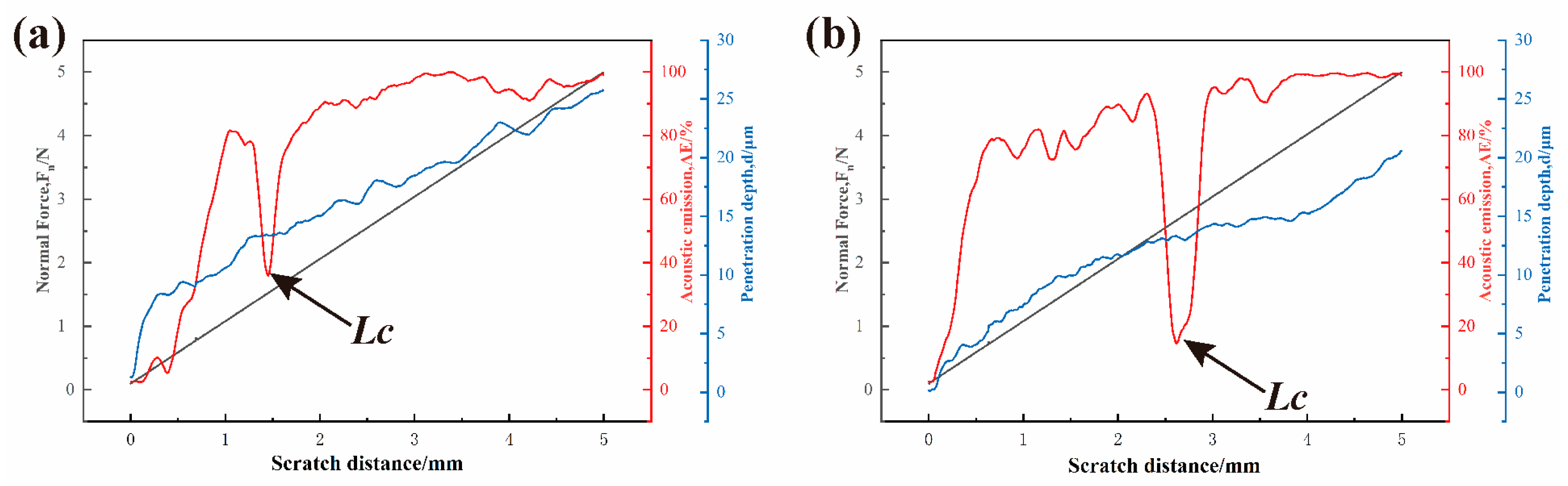
The results of the scratching tests demonstrated comparable behaviors across the three coatings. Initially, the AE signals remained stable due to the low modulus of the hydrogel. However, as the process of scratching progressed, there was an observed increase in the amplitude of the AE signals, with fluctuations occurring when the coating was fully removed. The adhesion strength was found to be 1.61 MPa, which increased to 2.02 MPa after PEI crosslinking. However, the coating thickness remained almost unchanged (12.650 μm to 12.670 μm), while the thickness of the two LbL coatings was 4.22 ± 0.03 μm.
In summary, the prepared self-assembled antifouling coatings have effective antifouling and drag reduction capabilities in a simulated marine environment, providing new research ideas for the design of new environmentally friendly marine antifouling coatings. The coating raw materials utilized in this study, namely PG, PEI, and PVP, are non-toxic polymeric compounds with well-documented industrial synthesis protocols, rendering them cost-effective alternatives. Cost analysis relative to conventional copper-based antifouling coatings demonstrates that the SS-PG@PVP/PEI coating maintains comparable economic viability. Moreover, the utilization of spray-coating technology significantly simplifies the fabrication process, enabling scalable manufacturing for marine vessels and submerged infrastructure.

Author Contributions

Conceptualization, H.S. and P.C.; methodology, H.S. and P.C.; software, Z.Z. and Q.H.; validation, S.W., H.S. and P.C.; formal analysis, H.S.; investigation, Z.Z. and S.W.; data curation, H.S. and P.C.; writing—original draft preparation, Z.Z.; writing—review and editing, H.S. and P.C.; supervision, P.C.; funding acquisition, H.S. and P.C. All authors have read and agreed to the published version of the manuscript.

Funding

This research was funded by the Open Fund Projects (No. CBGZJJ2023-2-12) of the State Key Laboratory of Special Surface Protection Materials and Application Technology, the Natural Science Foundation of China (No. 51905468), and the Jiangsu Province Graduate Student Practice and Innovation Program (SJCX23_ 1912).

Data Availability Statement

The authors will supply the relevant data in response to reasonable requests.

Conflicts of Interest

The authors declare no conflicts of interest.

References

  1. Zheng, N.; Jia, B.; Liu, J.; Wang, X.; Zhang, D.; Zhang, H.; Wang, G. Multi-strategy combined bionic coating for long-term robust protection against marine biofouling. J. Mater. Sci. Technol. 2025, 210, 265–277. [Google Scholar] [CrossRef]
  2. Liu, Z.; Zhao, H.; Jiang, T.; Qin, W. Influences of marine biofouling on the potential responses of polymeric membrane ion-selective electrodes. Sens. Actuators B Chem. 2025, 422, 136692. [Google Scholar] [CrossRef]
  3. Fragassa, C.; Mattiello, S.; Fronduti, M.; Del Gobbo, J.; Gagic, R.; Santulli, C. Prevention of biofouling due to water absorption of natural fiber composites in the aquatic environment: A critical review. J. Compos. Sci. 2024, 8, 532. [Google Scholar] [CrossRef]
  4. Jan, G.; Shafi, A.; Kirill, E.; Chun-lai, R.; Igal, S. Time Dependence of Lysozyme Adsorption on End-Grafted Polymer Layers of Variable Grafting Density and Length. Langmuir 2012, 25, 2122–2130. [Google Scholar]
  5. Schultz, M.P.; Bendick, J.A.; Holm, E.R.; Hertel, W.M. Economic impact of biofouling on a naval surface ship. Biofouling 2011, 27, 87–98. [Google Scholar] [CrossRef]
  6. Ali, A.; Culliton, D.; Fahad, S.; Ali, Z.; Kang, E.-T.; Xu, L. Nature-inspired anti-fouling strategies for combating marine biofouling. Prog. Org. Coat. 2024, 189, 108349. [Google Scholar] [CrossRef]
  7. Chen, T.L.; Lin, Y.P.; Chien, C.H.; Chen, Y.C.; Yang, Y.J.; Wang, W.L.; Chien, L.F.; Hsueh, H.Y. Fabrication of Frog-Skin-Inspired Slippery Antibiofouling Coatings Through Degradable Block Copolymer Wrinkling. Adv. Funct. Mater. 2021, 31, 2104173. [Google Scholar] [CrossRef]
  8. Chambers, L.; Wharton, J.; Wood, R.; Walsh, F.; Stokes, K. Techniques for the measurement of natural product incorporation into an antifouling coating. Prog. Org. Coat. 2014, 77, 473–484. [Google Scholar] [CrossRef]
  9. Salta, M.; Wharton, J.A.; Dennington, S.P.; Stoodley, P.; Stokes, K.R. Anti-biofilm performance of three natural products against initial bacterial attachment. Int. J. Mol. Sci. 2013, 14, 21757–21780. [Google Scholar] [CrossRef]
  10. Nehring, S. Long-term changes in Prosobranchia (Gastropoda) abundances on the German North Sea coast: The role of the anti-fouling biocide tributyltin. J. Sea Res. 2000, 43, 151–165. [Google Scholar] [CrossRef]
  11. Soroldoni, S.; Honscha, L.C.; Reis, F.O.; Duarte, F.A.; da Silva, F.M.R.; Pinho, G.L.L. Antifouling paint particles in soils: Toxic impact that goes beyond the aquatic environment. Ecotoxicology 2021, 30, 1161–1169. [Google Scholar] [CrossRef] [PubMed]
  12. Yu, W.; Koc, J.; Finlay, J.A.; Clarke, J.L.; Clare, A.S.; Rosenhahn, A. Layer-by-layer constructed hyaluronic acid/chitosan multilayers as antifouling and fouling-release coatings. Biointerphases 2019, 14, 051002. [Google Scholar] [CrossRef] [PubMed]
  13. Xu, G.; Pranantyo, D.; Xu, L.; Neoh, K.-G.; Kang, E.-T.; Teo, S.L.-M. Antifouling, antimicrobial, and antibiocorrosion multilayer coatings assembled by layer-by-layer deposition involving host–guest interaction. Ind. Eng. Chem. Res. 2016, 55, 10906–10915. [Google Scholar] [CrossRef]
  14. Li, S.; Huang, P.; Ye, Z.; Wang, Y.; Wang, W.; Kong, D.; Zhang, J.; Deng, L.; Dong, A. Layer-by-layer zwitterionic modification of diverse substrates with durable anti-corrosion and anti-fouling properties. J. Mater. Chem. B 2019, 7, 6024–6034. [Google Scholar] [CrossRef]
  15. Zhao, L.; Chen, R.; Lou, L.; Jing, X.; Liu, Q.; Liu, J.; Yu, J.; Liu, P.; Wang, J. Layer-by-Layer-Assembled antifouling films with surface microtopography inspired by Laminaria japonica. Appl. Surf. Sci. 2020, 511, 145564. [Google Scholar] [CrossRef]
  16. Nair, B. Final report on the safety assessment of polyvinylpyrrolidone (PVP). Int. J. Toxicol. 1998, 17 (Suppl. S4), 95–130. [Google Scholar] [CrossRef]
  17. Gultek, A.; Seckin, T.; Onal, Y.; Icduygu, M.G. Preparation and phenol captivating properties of polyvinylpyrrolidone-montmorillonite hybrid materials. J. Appl. Polym. Sci. 2001, 81, 512–519. [Google Scholar] [CrossRef]
  18. Nam, H.G.; Nam, M.G.; Yoo, P.J.; Kim, J.-H. Hydrogen bonding-based strongly adhesive coacervate hydrogels synthesized using poly (N-vinylpyrrolidone) and tannic acid. Soft Matter 2019, 15, 785–791. [Google Scholar] [CrossRef]
  19. Meng, H.; Li, Y.; Faust, M.; Konst, S.; Lee, B.P. Hydrogen peroxide generation and biocompatibility of hydrogel-bound mussel adhesive moiety. Acta Biomater. 2015, 17, 160–169. [Google Scholar] [CrossRef]
  20. McDonnell, G. The use of hydrogen peroxide for disinfection and sterilization applications. In PATAI’S Chemistry of Functional Groups; John Wiley & Sons: Hoboken, NJ, USA, 2009; pp. 1–34. [Google Scholar]
  21. Dogan, E.M.; Zalluhoglu, F.S.; Orbey, N. Effect of potassium ion on the stability and release rate of hydrogen peroxide encapsulated in silica hydrogels. AIChE J. 2017, 63, 409–417. [Google Scholar] [CrossRef]
  22. Munther, M.; Palma, T.; Angeron, I.A.; Salari, S.; Ghassemi, H.; Vasefi, M.; Beheshti, A.; Davami, K. Microfabricated biomimetic placoid scale-inspired surfaces for antifouling applications. Appl. Surf. Sci. 2018, 453, 166–172. [Google Scholar] [CrossRef]
  23. Wang, Y.; Jeon, E.J.; Lee, J.; Hwang, H.; Cho, S.; Lee, H. A phenol-amine superglue inspired by insect sclerotization process. Adv. Mater. 2020, 32, 2002118. [Google Scholar] [CrossRef] [PubMed]
  24. Liu, D.; Wang, H.; Dong, X.; Liu, X.; Dosta, S.; Zhang, C.; Cao, P. Enhancing antibacterial and anticorrosion properties of 304 stainless steel surfaces: A multi-modification approach based on DA/PEI/SiO2/AMPs. J. Coat. Technol. Res. 2023, 20, 979–994. [Google Scholar] [CrossRef]
  25. Wang, C.; Xiao, J.-K.; Xiao, S.-X.; Xu, G.-M.; Chen, J.; Zhang, C. Effect of Electrical Current on the Tribological Property of Cu-Graphite Brush. Tribol. Lett. 2024, 72, 29. [Google Scholar] [CrossRef]
  26. Johnson, K.L. Contact Mechanics; Cambridge University Press: Cambridge, UK, 1987. [Google Scholar]
  27. Oliver, W.C.; Pharr, G.M. An improved technique for determining hardness and elastic modulus using load and displacement sensing indentation experiments. J. Mater. Res. 1992, 7, 1564–1583. [Google Scholar] [CrossRef]
  28. Zhang, J.; Sun, T.; Hartmaier, A.; Yan, Y. Atomistic simulation of the influence of nanomachining-induced deformation on subsequent nanoindentation. Comput. Mater. Sci. 2012, 59, 14–21. [Google Scholar] [CrossRef]
  29. Elkins, J.; Marsh, J.L.; Lujan, T.; Peindl, R.; Kellam, J.; Anderson, D.D.; Lack, W. Motion predicts clinical callus formation: Construct-specific finite element analysis of supracondylar femoral fractures. J. Bone Jt. Surg. 2016, 98, 276–284. [Google Scholar] [CrossRef]
  30. Zhang, Q.; Wang, R.; Feng, B.; Zhong, X.; Ostrikov, K. Photoluminescence mechanism of carbon dots: Triggering high-color-purity red fluorescence emission through edge amino protonation. Nat. Commun. 2021, 12, 6856. [Google Scholar] [CrossRef]
  31. Katona, G.; Sipos, B.; Ambrus, R.; Csóka, I.; Szabó-Révész, P. Characterizing the drug-release enhancement effect of surfactants on megestrol-acetate-loaded granules. Pharmaceuticals 2022, 15, 113. [Google Scholar] [CrossRef]
  32. Muhammed, N.S.; Haq, B.; Al Shehri, D.; Al-Ahmed, A.; Rahman, M.M.; Zaman, E. A review on underground hydrogen storage: Insight into geological sites, influencing factors and future outlook. Energy Rep. 2022, 8, 461–499. [Google Scholar] [CrossRef]
  33. Karatas, H.; Townsend, E.C.; Cao, F.; Chen, Y.; Bernard, D.; Liu, L.; Lei, M.; Dou, Y.; Wang, S. High-affinity, small-molecule peptidomimetic inhibitors of MLL1/WDR5 protein–protein interaction. J. Am. Chem. Soc. 2013, 135, 669–682. [Google Scholar] [CrossRef]
  34. Xu, J.; Hou, Y.; Lian, Z.; Yu, Z.; Wang, Z.; Yu, H. Bio-inspired design of bi/tridirectionally anisotropic sliding superhydrophobic titanium alloy surfaces. Nanomaterials 2020, 10, 2140. [Google Scholar] [CrossRef] [PubMed]
  35. Oliveira, L.C.C.; Rodrigues, F.A.A.; Barbosa, C.R.d.S.; dos Santos, J.F.S.; Macêdo, N.S.; Silveira, Z.d.S.; Coutinho, H.D.M.; da Cunha, F.A.B. Antibacterial activity of the pyrogallol against Staphylococcus aureus evaluated by optical image. Biologics 2022, 2, 139–150. [Google Scholar] [CrossRef]
  36. Ni, N.; Choudhary, G.; Li, M.; Wang, B. Pyrogallol and its analogs can antagonize bacterial quorum sensing in Vibrio harveyi. Bioorg. Med. Chem. Lett. 2008, 18, 1567–1572. [Google Scholar] [CrossRef] [PubMed]
  37. Helander, I.M.; Alakomi, H.-L.; Latva-Kala, K.; Koski, P. Polyethyleneimine is an effective permeabilizer of gram-negative bacteria. Microbiology 1997, 143, 3193–3199. [Google Scholar] [CrossRef]
  38. Kang, X.; He, Y.; Lin, N.; Zhang, M.; Yan, Y.; Huang, J. A study of the preparation and properties of dense binderless titanium carbonitride-based ceramics. J. Alloys Compd. 2020, 843, 155941. [Google Scholar] [CrossRef]
  39. Yang, H.; Qin, L.; Zhao, W.; Mawignon, F.J.; Guo, H.; Wu, Y.; Zhang, Y.; Dong, G. Eco-friendly polysaccharide coatings for antifouling and drag-reduction and potential application for marine devices. Friction 2024, 12, 726–744. [Google Scholar] [CrossRef]
  40. Si, R.; Chen, Y.; Wang, D.; Yu, D.; Ding, Q.; Li, R.; Wu, C. Nanoarchitectonics for high adsorption capacity carboxymethyl cellulose nanofibrils-based adsorbents for efficient Cu2+ removal. Nanomaterials 2022, 12, 160. [Google Scholar] [CrossRef]
  41. Singla, A.; Singh, N.K.; Singh, Y.; Jangir, D.K. Micro and nano-crystalline diamond coatings of co-cemented tungsten carbide tools with their characterization. J. Bio-Tribo-Corros. 2021, 7, 35. [Google Scholar] [CrossRef]
  42. Kim, H.-K.; Kim, S.-M.; Lee, S.-Y. Mechanical properties and thermal stability of CrZrN/CrZrSiN multilayer coatings with different bilayer periods. Coatings 2022, 12, 1025. [Google Scholar] [CrossRef]
Figure 1. Fabrication of SS-PG@PVP/PEI LbL-deposited multilayer coatings.
Jmse 13 00568 g001
Figure 2. Schematic diagram of the paper disc method for measuring the diameter of the bacteriostatic zone.
Jmse 13 00568 g002
Figure 3. Results of the analysis of the surface components of the samples. FT-IR spectra (a), XPS survey spectra (b), C1s, N1s, O1s spectra of SS-PG@PVP (ce), and C1s, N1s, O1s spectra of SS-PG@PVP/PEI (fh).
Jmse 13 00568 g003
Figure 4. Surface water contact angle and roughness of SS, SS-PG@PVP, and SS-PG@PVP/PEI samples (a); optical microscope photographs (bd) and corresponding 3D contour maps (b1d1) for each sample.
Jmse 13 00568 g004
Figure 5. SEM images of the coated surfaces. SS-PG@PVP (a), SS-PG@PVP/PEI (b); (a1,b1) are further enlarged photos of the surface of each sample, and (a2,b2) are side views of each sample.
Jmse 13 00568 g005
Figure 6. Solid medium after the formation of the inhibition zone (a); quantitative analysis of the diameter of the inhibition zone (b).
Jmse 13 00568 g006
Figure 7. CLSM images of S. aureus adhesion on SS (a), SS-PG@PVP (b), and SS-PG@PVP/PEI (c), E. coli adhesion on SS (d), SS-PG@PVP (e), and SS-PG@PVP/PEI (f), P. tricornutum adhesion on SS (g), SS-PG@PVP (h), and SS-PG@PVP/PEI (i).
Jmse 13 00568 g007
Figure 8. Quantitative analysis of microbial adhesion inhibition rate on the surface of each sample obtained by calculating the fluorescence intensity using ImageJ software and by Equation (1).
Jmse 13 00568 g008
Figure 9. COF curves for each specimen: dry friction (a), artificial seawater infiltration (b).
Jmse 13 00568 g009
Figure 10. Results of the MST experiment for SS-PG@PVP (a) and SS-PG@PVP/PEI (b).
Jmse 13 00568 g010
Table 1. Micro-scratch test parameters.
ParameterValue
Acquisition Rate/(Hz)30
Begin Load/(mN)1000
End Load/(mN)5000
Loading Rate/(mN/min)19,600
Speed/(mm/min)2
Length/(mm)5
Acoustic Emission Sensitivity9
Table 2. Poisson’s ratio and Young’s modulus of diamond indenter and stainless steel substrate, calculated values of reduced Young’s modulus.
MaterialPoisson RatioYoung’s Modulus (MPa)References
Diamond (ball indenter)0.071140[28]
SS 304 (substrate)0.3210[29]
Calculated reduced Young’s modulusN/A192.0776N/A
Table 3. XPS quantitative analysis results.
SamplesC (at%)N (at%)O (at%)
SS-PG@PVP47.819.5742.63
SS-PG@PVP/PEI45.7510.7743.48
Table 4. Surface COF parameters for different samples.
SamplesAverage COF (Dry)Average COF (Artificial Seawater Infiltration)
SS0.500.38
SS-PG@PVP0.710.27
SS-PG@PVP/PEI0.660.24
Disclaimer/Publisher’s Note: The statements, opinions and data contained in all publications are solely those of the individual author(s) and contributor(s) and not of MDPI and/or the editor(s). MDPI and/or the editor(s) disclaim responsibility for any injury to people or property resulting from any ideas, methods, instructions or products referred to in the content.

