Article

Mechanical Evaluation of Casing in Multiple Thermal Recovery Cycles for Offshore Heavy Oil Wells

1
School of Mechanical Engineering, Yangtze University, Jingzhou 434023, China
2
The Seventh Geological Brigade of Hubei Geological Bureau, Yichang 443000, China
*
Author to whom correspondence should be addressed.
J. Mar. Sci. Eng. 2025, 13(3), 597; https://doi.org/10.3390/jmse13030597
Submission received: 24 February 2025 / Revised: 12 March 2025 / Accepted: 15 March 2025 / Published: 18 March 2025

Abstract

:
China’s offshore heavy oil resources are abundant but underutilized. Circulating steam stimulation enhances production while increasing casing failure risks in thermal recovery wells. Accurately assessing casing performance after repeated thermal cycles is crucial for ensuring wellbore integrity. This paper presents tensile and creep experiments on TP110H casing under cyclic temperatures. The temperature distribution within the “casing-cement sheath-stratum” system is derived using heat transfer theory. Stress and displacement equations are established based on thick-walled cylinder theory and thermo-elasticity. Thermal coupling analysis assesses casing stress in straight, inclined, and sidetrack well sections. Key factors, including steam injection pressure, in situ stress, cement modulus, and prestress, are analyzed for their effects on cumulative strain below the packer. Strain-based methods evaluate casing safety. Results show that under thermal cycling at 350 °C, after 16 cycles, the casing’s elastic modulus, yield strength, and tensile strength decrease by 15.3%, 13.1%, and 10.1%, respectively, while the creep rate increases by 16.0%. Above the packer, the casing remains safe, but the lower section may be at risk. Using low-elasticity cement, higher steam injection pressure, and prestressing can help improve casing performance. This study provides guidance on enhancing casing safety and optimizing steam stimulation parameters.

1. Introduction

Heavy oil resources are abundant worldwide and constitute over 80% of the remaining global oil reserves [1]. Offshore heavy oil deposits form a significant proportion of these resources and are mainly located in the Gulf of Mexico, Brazilian waters, the North Sea, the Mediterranean, and the Zatchi Sea [2,3,4,5]. China’s offshore areas hold vast reserves of high-viscosity heavy oil (viscosity exceeding 350 mPa·s), yet the development of these resources remains limited [6,7]. Unlike the well-established thermal recovery techniques used for onshore heavy oil, offshore thermal recovery poses unique challenges [8]. These include restricted operating space, heightened safety risks, and significantly higher costs [9]. Adapting onshore thermal recovery experiences to offshore environments is exceedingly difficult, making this a globally acknowledged technical bottleneck [10]. Therefore, addressing these challenges is critical to increasing the utilization of offshore heavy oil reservoirs and unlocking their full potential [11].
Traditional cold recovery methods, such as water flooding and chemical flooding, are ineffective due to heavy oil’s poor fluidity, driven by its high viscosity and density [12,13,14]. Thermal recovery has emerged as the only viable solution for offshore heavy oil development, thanks to the temperature sensitivity of heavy oil viscosity [15,16,17]. Increasing the temperature significantly reduces viscosity, improving fluidity and making extraction feasible [18]. To date, a variety of thermal recovery techniques have been developed for different reservoir conditions, providing essential support for the efficient and economical exploitation of heavy oil resources [19]. Currently, circulating steam stimulation is the primary method for heavy oil recovery, involving the injection of high-temperature steam into the reservoir through an insulated oil pipe at a controlled pressure [20,21]. Upon reaching the oil layer, the steam heats the casing and cement sheath, subsequently transferring heat to the surrounding oil [22,23]. This process reduces the viscosity of heavy oil, improves its flow characteristics, and ultimately facilitates efficient extraction [24].
Repeated steam stimulation causes uncoordinated deformation and thermal stress accumulation between the casing and cement, resulting from significant temperature gradients [25]. This process can result in casing damage, including necking, rupture, and misalignment fractures, posing significant risks to the stability and continuous production of thermal recovery wells [26]. Thus, ensuring casing stability has become a key research focus, essential for improving wellbore sealing, supporting heavy oil recovery, and extending wellbore lifespan [27,28,29].
Scholars have conducted extensive research on casing from the perspectives of wellbore heat transfer, stress influencing factors, and safety evaluation. Analytical calculations of casing heat transfer and stress in thermal recovery wells are well established and remain widely applied. Zhu et al. [30] developed a mathematical model to calculate the plastic limit load of casing defects under the high-temperature and high-pressure conditions of steam injection. Hou et al. [31] observed that the combined effects of casing diameter reduction and creep deformation induce localized tension in the cement sheath at the cementing interface. Li et al. [32] proposed a casing damage model considering mudstone hydration, corrosion, and sand production, with the random forest method achieving a 92.3% recall rate for damaged wells. H. Wang et al. [33] evaluated casing safety under thermal stress and annular pressure buildup (APB), demonstrating that nitrogen injection and rupture disks effectively reduced APB by over 75%, highlighting the need to maintain APB within safe limits for wellbore integrity.
To summarize, previous research has investigated the distribution of temperature and stress within the wellbore, as well as casing damage issues in thermal recovery wells [34]. Significant progress has been made in optimizing steam injection parameters and developing preventive measures [35]. However, most studies focus on the mechanical properties of casing under continuous high-temperature conditions. In contrast, research on the mechanical behavior of casing subjected to multiple cycles of high and low temperatures remains limited. Systematic experimental studies on casing performance variations across different well sections under thermal cycling at high temperatures are still scarce. In view of the above, this paper takes the Phase II production of the Lvda 5-2 North Oilfield as an example. This ultra-heavy oil field is located in Liaodong Bay, Bohai Sea. The typical development strategy for this field involves sidetrack drilling after eight cycles of thermal recovery, followed by an additional eight cycles, aiming to maximize economic efficiency. However, this approach highlights the need for casing to withstand the operational demands of the “8 + 8” thermal recovery cycles.
The motivation for this study is to clarify the mechanical properties of casing in different well sections under high- and low-temperature cycles, qualitatively analyze wellbore temperature and stress variations, and assess the impact of well structure and key parameters on casing behavior. It provides a reference for reducing casing failure risk and optimizing steam injection cycles in the Lvda 5-2 North oilfield. The main contributions of this paper are as follows: (1) experimental testing of the mechanical properties of TP110H casing under repeated thermal cycling; (2) development of an analytical model for the temperature and stress fields within the “casing-cement sheath-formation” system under steam injection; (3) thermal coupling analysis of well structure to assess casing behavior, simulation of cumulative strain, and evaluation of influencing factors in the lower packer region under cyclic thermal and pressure changes, with casing safety assessed using the strain design method.

2. Materials and Experiments

TP110H steel is a specialized casing material designed for heavy oil thermal recovery wells, where steam injection temperatures typically reach around 350 °C [36]. Field practice indicates that cyclic thermal loads, when combined with mechanical stresses, can compromise the structural integrity of casing [37,38]. To study these effects and prepare for parameterizing the finite element casing model, tensile and creep tests on casing material were conducted after multiple thermal cycles. Parameters such as elasticity modulus, yield strength, tensile strength, elongation at break, section shrinkage, and creep rate were analyzed.
The TP110H casing used in this study has an outer diameter of 244.48 mm and a wall thickness of 11.99 mm. Before mechanical testing, the casing samples underwent controlled high- and low-temperature thermal cycles using the setup shown in Figure 1.
Before thermal cycling, the casing was secured in the temperature control unit. The system initially maintained a 50 °C environment, where the casing was preheated and held for 30 min. Then, the temperature gradually increased to 350 °C and was maintained for 60 min. Finally, the heating system was switched off, allowing the casing to cool naturally back to 50 °C, completing one thermal cycle. The samples were subjected to 1 to 16 cycles, as specified for different test groups. After completing the thermal cycles, a standard specimen was machined to the dimensions shown in Figure 2a. The final machined specimen is presented in Figure 2b. To minimize experimental errors during thermal cycling, tensile, and creep tests of TP110H casing, strict control measures were implemented to ensure consistency in specimen preparation, heating rates, and temperature stabilization times. Furthermore, three parallel specimens were tested under each condition, and their average values were used for analysis to enhance result reliability.

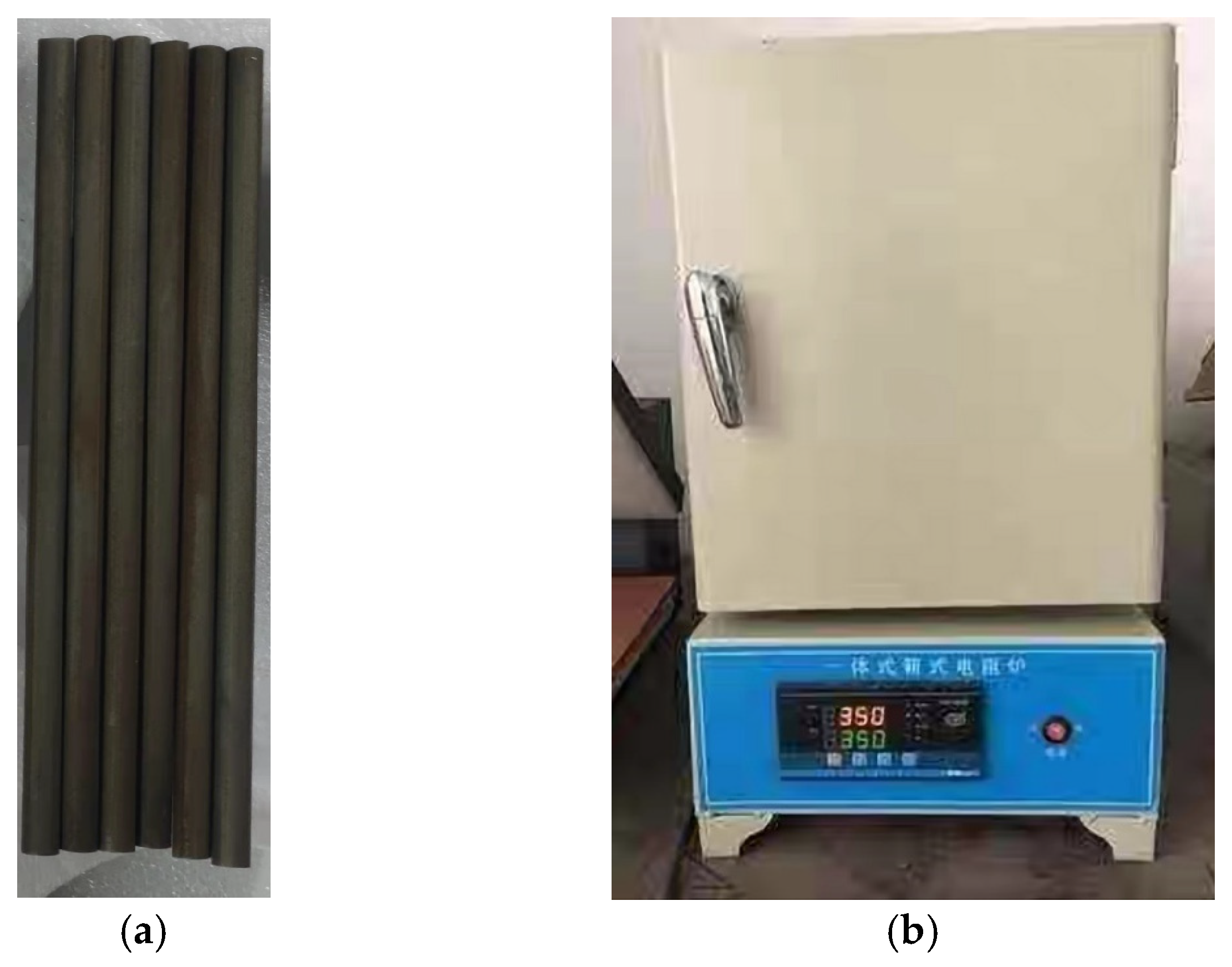
2.1. Tensile Experiment

Before testing, specimens were inspected for defects to ensure that only qualified samples proceed. The tensile test for the TP110H casing specimen was conducted using a universal testing machine [39], as shown in Figure 2c. Tensile testing was conducted at three constant temperatures: 50 °C, 200 °C, and 350 °C.
The experimental procedure was as follows [40,41]: (1) mark the original gauge length, measure, and record the size of the specimen; (2) switch on the testing machine and set the test parameters; (3) install the specimen on the testing machine and attach an extensometer; (4) before applying the test force, heat the specimen to the specified test temperature using a heating furnace, maintain it at this temperature for at least 15 min, and then apply the load after the extensometer output stabilizes. The entire process was controlled by beam displacement, with a displacement rate of 0.375 mm/min in the elastic phase and 2.1 mm/min after the steel yields. Load and displacement curves were recorded throughout the tensile test until the specimen ruptured. Figure 2b,d compare the specimens before and after tensile fracture. The fracture occurred in the right third of the parallel section, with the fracture surface exhibiting pronounced necking.
Figure 3 shows the tensile stress–strain curves for TP110H steel after varying numbers of thermal cycles, revealing four distinct phases: elastic deformation, yield, strengthening, and shrink. At 50 °C, TP110H steel exhibits the highest stress values in the elastic, yield, and strengthening stages, followed by 200 °C, while 350 °C results in the lowest values. At the same strain, stress decreases as temperature increases. After yielding, the stress rises more slowly with strain and drops rapidly after reaching the tensile strength, leading to necking and fracture. This indicates that at higher temperatures, yielding occurs earlier, plastic deformation begins sooner, and ultimate tensile strength decreases significantly. While different thermal cycles affect the stress–strain response, their impact on strength is minimal.
Key parameters, such as modulus of elasticity, yield strength, tensile strength, elongation, and section shrinkage, are summarized in Figure 4. Yield and tensile strength changes are shown in Table 1. As shown in Figure 4a, the elastic modulus of TP110H steel significantly decreases with temperature, reflecting reduced resistance to elastic deformation at higher temperatures. For instance, without thermal cycling, the elastic modulus is 203 GPa at 50 °C, decreases by 4.9% to 193 GPa at 200 °C, and further declines by 15.3% to 172 GPa at 350 °C. Notably, when comparing different thermal cycles at a constant temperature, minimal variation is observed in the modulus, indicating that thermal cycling has a negligible effect on TP110H casing’s elastic modulus.
At high temperatures, casing materials endure significant thermal stress. Exceeding the yield strength causes plastic deformation, which accumulates over time and may exceed strain limits, risking failure. Thus, ensuring TP110H steel’s strength stability under cyclic thermal conditions is vital for reliable steam injection. Figure 4b shows that temperature has a greater effect on the yield strength of TP110H steel than cycling frequency. Specimens subjected to 16 thermal cycles exhibit yield strength reductions of 4.3% from 50 °C to 200 °C and 13.1% when raised to 350 °C. As shown in Table 1, yield strength declines sharply after the first thermal cycle, with further reductions as cycles progress, particularly at higher temperatures. At 50 °C, yield strength decreases by 8.1% after 16 cycles. Similarly, at 200 °C, the reduction is 9.0%, and at 350 °C, it is 10.8%.
Tensile strength represents the maximum tensile force a casing can withstand, indicated by the peak stress on the tensile stress–strain curve. As shown in Figure 4c, tensile strength decreases with increasing temperature and thermal cycles, though to a lesser extent than yield strength. This indicates that tensile strength is less sensitive to temperature and cycling. Specimens exposed to 16 cycles show a 4.0% reduction in tensile strength at 200 °C and a 10.1% decrease at 350 °C compared to that at 50 °C. Combined with Table 1, this indicates that at 50 °C, tensile strength decreases by 4.9% after 16 thermal cycles. Similarly, at 200 °C, the reduction is 5.6%, and at 350 °C, it is 6.4%. Both yield and tensile strengths comply with the GB/T 34907-2017 standard [42], which limits strength reduction in high-temperature casings for heavy oil steam injection wells to 20% [43]. Therefore, the TP110H steel casing meets the production requirements.
Elongation at break, which represents the material’s plastic deformation capacity, increases with both temperature and thermal cycling. Similarly, section shrinkage, defined as the percentage decrease in cross-sectional area after fracture, serves as an indicator of material plasticity. As shown in Figure 4d, TP110H steel exhibits a minimum elongation of 14.3% at 50 °C without thermal cycling and a maximum elongation of 18.8% at 350 °C after 16 cycles. This trend indicates an enhanced plastic deformation capacity at elevated temperatures and under repeated thermal cycling. Furthermore, TP110H steel specimens show the lowest section shrinkage (62.3%) at 50 °C without thermal cycling and the highest shrinkage (69.9%) at 350 °C after 16 cycles. The observed increase in section shrinkage with temperature and cycling frequency suggests a gradual improvement in plasticity under prolonged thermal exposure.

2.2. Creep Experiment

The preparation process mirrors that of the tensile tests, with specimens subjected to 0 to 16 thermal cycles within a temperature range of 50–350 °C. In this process, once the specimen stabilizes at 350 °C, the load is applied, and the creep test continues until it reaches a steady-state creep rate. To evaluate the creep behavior of TP110H steel, four stress levels (400 MPa, 500 MPa, 600 MPa, and 700 MPa) were tested at 350 °C after up to 16 thermal cycles. For each condition, three parallel specimens were tested, and their results were averaged to determine the final outcome.
Figure 5 presents the creep–strain curves for TP110H steel under varying thermal cycles, showing that specimens entered the steady-state creep phase. At higher stress loads, the creep–strain curve exhibited a steeper slope, indicating a higher steady-state creep rate. The creep rate is a key indicator of material creep performance. Based on these curves, the steady-state creep rates were calculated and are presented in Figure 6. The figure shows that the creep rate of TP110H steel increases with both the number of thermal cycles and the applied stress level, with higher stress levels amplifying the creep behavior. The loading stress increase from 400 MPa to 700 MPa elevates the creep rate by an order of magnitude, highlighting the significant roles of both thermal cycles and stress in determining the creep rate of TP110H casing material. For instance, under a stress of 400 MPa, the creep rate increased from 3.17 × 10⁻⁸%/s to 4.04 × 10⁻⁸%/s (an increase of 27.4%) after 16 thermal cycles. For the highest stress load of 700 MPa, the creep rate increased from 1.25 × 10⁻⁷%/s to 1.45 × 10⁻⁷%/s, reflecting a 16.0% increase after 16 thermal cycles.

3. Temperature Stress Analysis of Wellbore in Thermal Wells
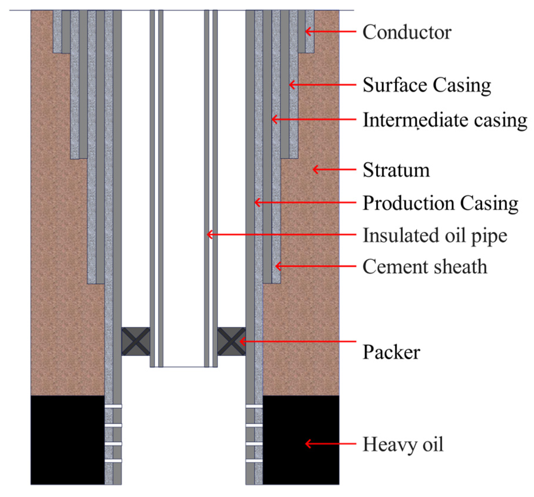
3.1. Well Structure

The structure of a steam stimulation thermal recovery well is shown in Figure 7. These casing strings, varying in diameter and thickness, combine in a hierarchical arrangement to form the wellbore structure. This structure serves multiple purposes, including supporting unstable formations, providing channels for gas injection and oil recovery, and connecting wellhead equipment [44].
Compared to conventional oil wells, steam stimulation thermal recovery wells exhibit two notable differences [45,46]. First, the cement surrounding the production casing must extend to the wellhead. If this is not achieved, issues can arise during steam injections, as uncemented sections above the cement top may experience upward movement, leading to wellhead lifting. Second, a thermal insulation oil tubing is installed within the production casing, reaching the top of the production layer. In the annulus between the oil tubing and casing, a thermal packer is positioned, comprising an inner tube, an insulating layer, and an outer tube. Additionally, the production casing in the oil formation is perforated, allowing high-temperature steam to penetrate the reservoir during the steam injection stage for effective heat transfer. This structure facilitates effective steam injection while enhancing well stability and thermal insulation, crucial for long-term well integrity and production efficiency in thermal recovery applications.

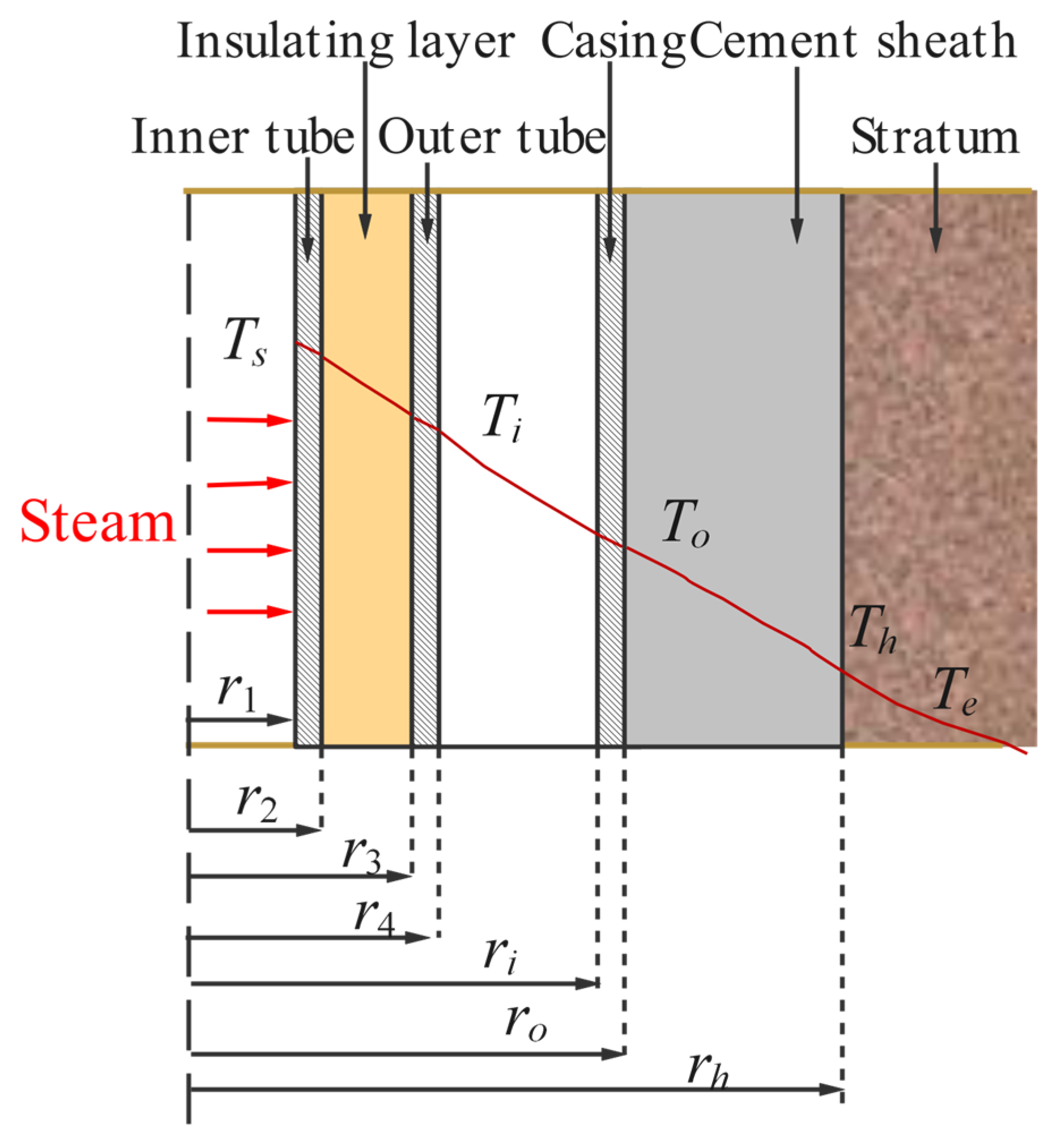
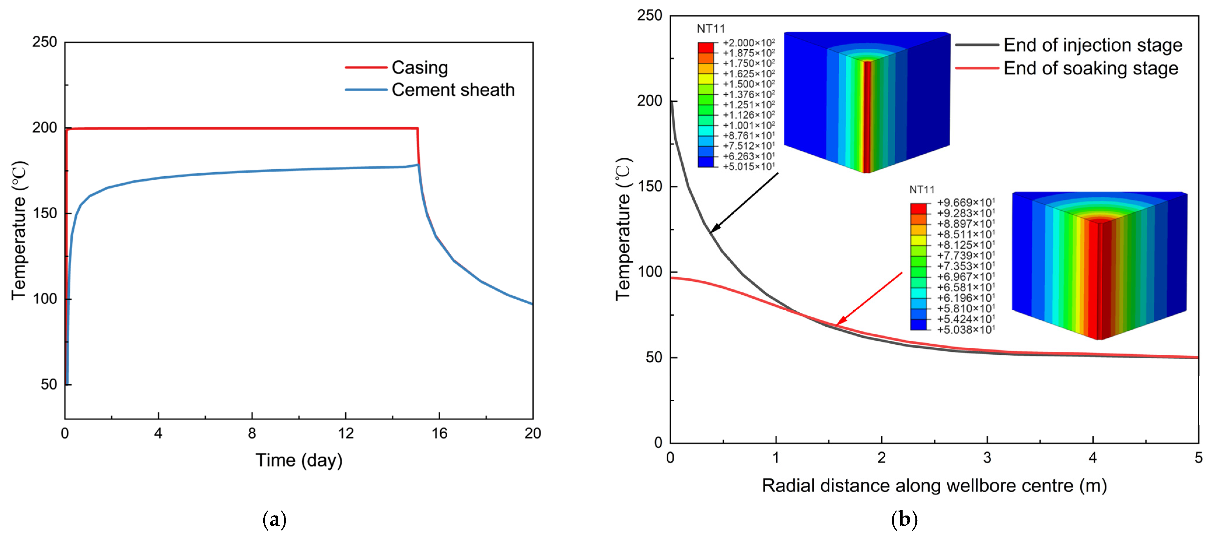
3.2. Temperature Analysis of Wellbore

The thermal recovery wellbore structure resembles a composite cylindrical system [47]. Due to the axisymmetric nature of this configuration, the temperature remains constant along the length and circumference, varying only at radial distances. Consequently, heat transfer from the injected high-temperature steam within the well can be approximated as one dimensional, occurring radially, while the axial heat transfer can be disregarded. For simplification, heat transfer from the wellbore center to the outer boundary of the cement sheath is treated as one-dimensional steady-state heat transfer, while beyond the cement sheath’s boundary, heat transfer is modeled as one-dimensional unsteady-state heat transfer.
Based on the steady-state heat transfer equation, the heat flux through an infinitesimal length dL of the wellbore per unit time is given by [48]
d Q = T s T h R d L
where Ts is the injected steam temperature (°C), Th is the cement sheath’s outer boundary temperature (°C), and R is the total thermal resistance (K/W).
Figure 8 illustrates the heat transfer mechanism during the steam injection process. Heat flows from the high-temperature steam in the wellbore to the cement sheath’s outer boundary, passing through the various components: inner pipe → insulation layer → outer pipe → annular space → casing → cement sheath. R for this heat transfer is [49]
R = 1 2 π 1 h 1 r 1 + l n r 2 r 1 k A + l n r 3 r 2 k B + l n r 4 r 3 k A + 1 r 4 h 2 + h 3 + l n r o r i k C + l n r h r o k D
where r1 and r2 are the inner and outer radii of the inner pipe (m), r3 and r4 are the inner and outer radii of the outer pipe (m), ri and ro are the inner and outer radii of the casing (m), rh is the outer radius of the cement sheath (m), h1 is the convective heat transfer coefficient between high-temperature steam and the inner pipe wall (W/(m2·k)), h2 and h3 are the convective and radiative heat transfer coefficients between the annular space and casing wall (W/(m2·k)), kA, kB, kC, and kD are the thermal conductivities of the tubing, insulation, casing, and cement sheath, respectively (W/(m·k)).
The heat transfer from the outer boundary of the cement sheath to the surrounding stratum is governed by a one-dimensional, time-dependent (non-stationary) heat conduction process [50]. Using the approximate solution derived by Ramey, the heat flux for a differential length dL is given by
d Q = 2 π k E T h T e f t d L
where kE is the thermal conductivity of the stratum (W/(m·K)), Te is the initial stratum temperature (°C), and f(t) is a time-dependent function of the stratum’s thermal conductivity.
Typically, the temperature of the stratum increases with depth, and the increase in temperature per 100 m of depth is known as the geothermal gradient. To estimate the stratum temperature at a given depth, based on the average annual surface temperature, the following equation is used [51]:
T e = T 0 + 0.01 α T L
where T0 is the mean annual surface temperature (°C), αT is the geothermal gradient (°C/m), and L is the vertical depth (m).
According to Hasan’s [52] empirical model, the time function f(t) is expressed as
f t = 1.1281 a t r 2 1 0.3 a t r 2 ,     t 1.5 r 2 a 0.5 l n a t r 2 + 0.4063 1 + 0.6 r 2 a t ,     t > 1.5 r 2 a
where a is the stratum’s thermal diffusivity (m2/d) and t is the steam injection duration (days).
By equating the heat flux from the wellbore center to the cement sheath’s outer boundary with the heat flux from the cement sheath to the stratum, the temperature at the cement sheath-stratum interface, Th can be calculated. Similarly, the inner wall temperature of the casing, Ti, can be determined through a series of energy balance equations.
T h = 2 π k E T e R + T s f t f t + 2 π k E R
T i = T h + l n r o r i 2 π k C + l n r h r o 2 π k D T s T h R

3.3. Stress Analysis of Casing

Under high-temperature steam injection, the wellbore experiences internal and external pressures and thermal stresses, leading to casing radial deformation and significant radial compressive stresses at the cement sheath interface. To simplify the analysis of temperature and stress distributions, the following assumptions are made [49,53]: (1) The casing, cement sheath, and stratum are considered homogeneous isotropic materials. (2) The casing is centrally aligned, defect-free, and the cement sheath has no defects or eccentricities. (3) The interfaces between layers are tightly bonded without relative slippage, allowing the casing, cement sheath, and stratum to be modeled as three concentric thick-walled cylinders, with the formation’s outer boundary treated as infinitely large.

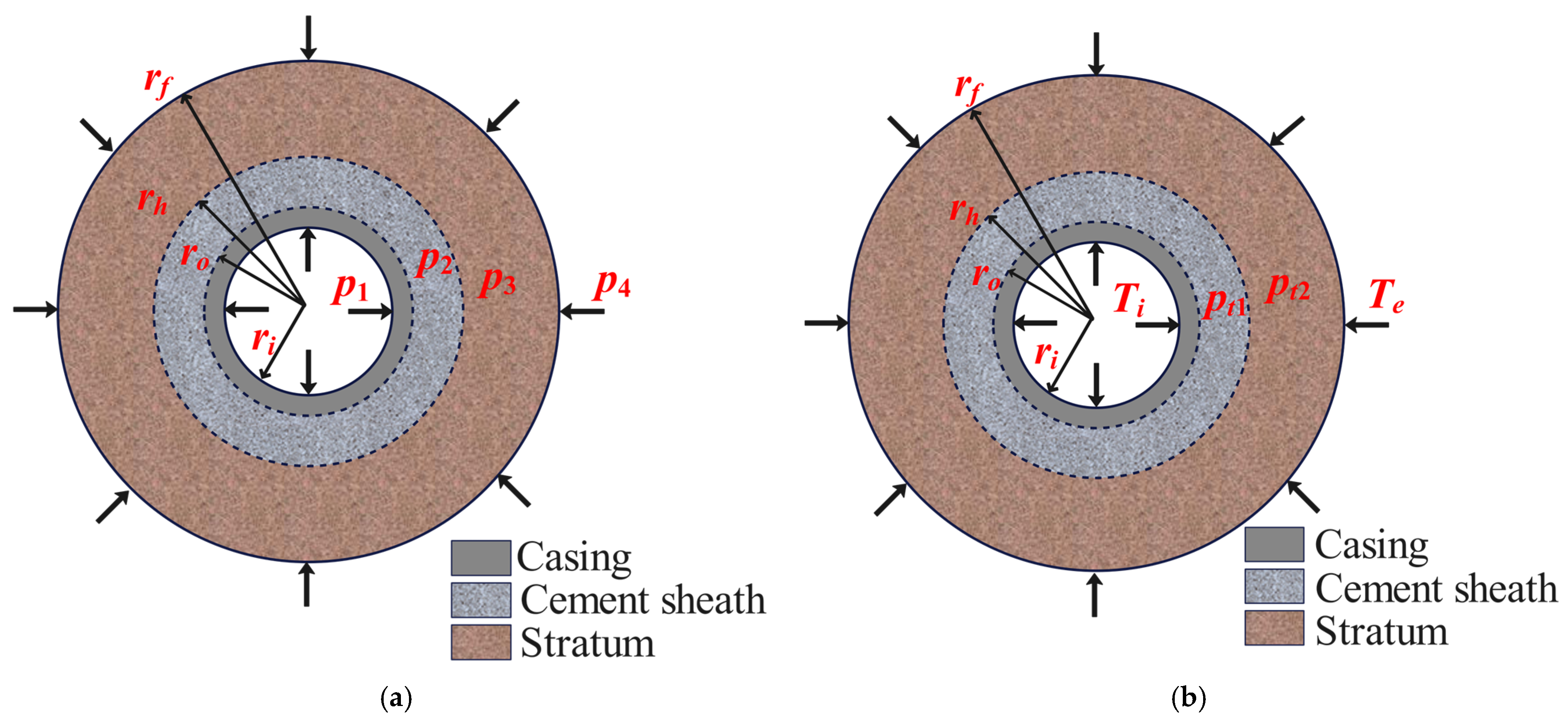
3.3.1. Stress and Displacement of the Casing Under Internal and External Pressures

In the “casing-cement sheath-stratum” model, the mechanical behavior of this multi-layered assembly is analyzed as a thick-walled cylinder problem under uniform internal and external pressures. As illustrated in Figure 9a, p1 and p4 induce contact pressures between the layers: p2 at the interface of the casing and cement sheath, and p3 at the interface of the cement sheath and formation.
The casing is subjected to internal pressure and the contact pressure exerted by the cement sheath. Based on Lamé’s theory, the radial and circumferential stresses are determined [54].
σ r = r i 2 r o 2 ( p 2 p 1 ) r o 2 r i 2 1 r 2 + r i 2 p 1 r o 2 p 2 r o 2 r i 2 σ θ = r i 2 r o 2 ( p 2 p 1 ) r o 2 r i 2 1 r 2 + r i 2 p 1 r o 2 p 2 r o 2 r i 2
where σr and σθ are the radial and circumferential stress of the casing under internal and external pressures (Pa), p1 is the internal pressure on the casing’s inner wall (Pa), and p2 is the contact pressure between the casing and cement sheath (Pa).
The radial displacement of the casing can be expressed as
u r = 1 E c 1 + μ c r i 2 r o 2 ( p 2 p 1 ) r o 2 r i 2 r + 1 μ c r i 2 p 1 r o 2 p 2 r o 2 r i 2 r
where ur is the radial displacement of the casing under internal and external pressures (m), Ec is the elastic modulus of the casing (Pa), and μc is Poisson’s ratio of the casing.
Similarly, using the principles of thin-walled cylinder stress and Lamé’s theory, the circumferential stress, radial stress, and deformation of the cement sheath and stratum can be obtained. By enforcing the continuity of radial displacement across layers, the following conditions hold: (a) The radial displacement of the casing’s outer wall equals that of the cement sheath’s inner wall. (b) The radial displacement of the cement sheath’s outer wall equals that of the stratum’s inner wall. Thus, p 2 and p 3 can be determined. Substituting these values into the stress expressions yields the complete stress field distribution within the casing, cement sheath, and stratum under the combined effects of internal pressure and ground stress.

3.3.2. Stress and Displacement of the Casing Under Thermal Loading

The combined body is subjected to thermal stresses, as shown in Figure 9b. Thermal stress arises from the casing wall temperature Ti and the formation edge temperature Te. Thermal loading generates contact pressures: pt1 between the casing and cement sheath, and pt2 between the cement sheath and formation.
Using thermal stress principles for thick-walled cylinders, the constitutive equation for thermal stress is [55]
ε t r = 1 E σ t r μ σ t r + σ t z + α T ε t θ = 1 E σ t θ μ σ t z + σ t r + α T ε t z = 1 E σ z μ σ t θ + σ t r + α T
For the plane strain condition ε z = 0 , it follows that
σ t z = μ σ t θ + σ t r α E T
The stress balance equation is
d σ t r d r + σ t r σ t θ r = 0
The displacement component under thermal stress is expressed as
u = α 1 + μ 1 μ 1 r a r T r d r + C 1 r + C 2 r
Further simplification provides the stress component under thermal stress as [53]
σ t r = E 1 + μ α 1 + μ 1 μ 1 r 2 T a r r d r + C 1 1 2 μ C 2 r 2 σ t θ = E 1 + μ α 1 + μ 1 μ 1 r 2 T a r r d r + C 1 1 2 μ + C 2 r 2 α 1 + μ 1 μ T
where α is the linear thermal expansion coefficient of the material (°C−1) and T is the radial temperature distribution function within the cylinder, represented as T = T ( r ) . C1 and C2 are solution constants.
For the casing, the boundary conditions at the inner and outer walls are given by
σ r 2 r i = 0 , σ r 2 r o = p t 1
By applying the boundary conditions to Equation (10), the solution constants for the casing stress component expressions can be derived.
C 1 = p t 1 r o 2 + α E 1 μ r i r o T r d r 1 r o 2 r i 2 1 + μ 1 2 μ E C 2 = p t 1 + α E 1 μ 1 r o 2 r i r o T r d r r i 2 r o 2 r o 2 r i 2 1 + μ E
Similarly, the stresses and displacements of the cement sheath and formation under thermal loading can be determined. Based on radial displacement continuity across layers, the displacement of the casing’s outer wall equals that of the cement sheath’s inner wall, and the displacement of the cement sheath’s outer wall equals that of the formation’s inner wall. Using these conditions, the contact pressures pt1 and pt2 can be calculated. Substituting these values into the stress component expressions yields the complete stress distribution for the casing, cement sheath, and formation under thermal loading. Finally, by superimposing the results from Equations (8) and (14), the casing stress in the thermal recovery well can be determined.

3.4. Casing Strain Design Method

The strain design method, aimed at ensuring casing strength after drilling and completion, uses plastic strain in the casing as the evaluation criterion [56,57,58]. This method comprehensively accounts for factors contributing to strain, including thermal stress from high temperatures, high-temperature creep, and mechanical stress. It requires that the casing does not yield during drilling and completion, while allowing plastic strain during production, provided that total casing deformation remains within the specified allowable strain limit [59]. This approach thus serves as a criterion for assessing casing safety.
Once casing yield occurs, residual stress and yield strength within the casing vary with each subsequent “injection-soaking-production” cycle. Consequently, the expression for the casing strain design method, based on cumulative damage criteria, is as follows:
ε = 1 N ε i ε = δ F
where ε is the cumulative strain in the casing (%), ε i is the cumulative strain increment in the casing after the i-th cycle (%), ε is the permissible strain of the casing (%); δ is the uniform elongation of the casing (%), and F is the strain design safety factor.

3.5. Numerical Simulation of Casing Under Thermal Recovery Cycles

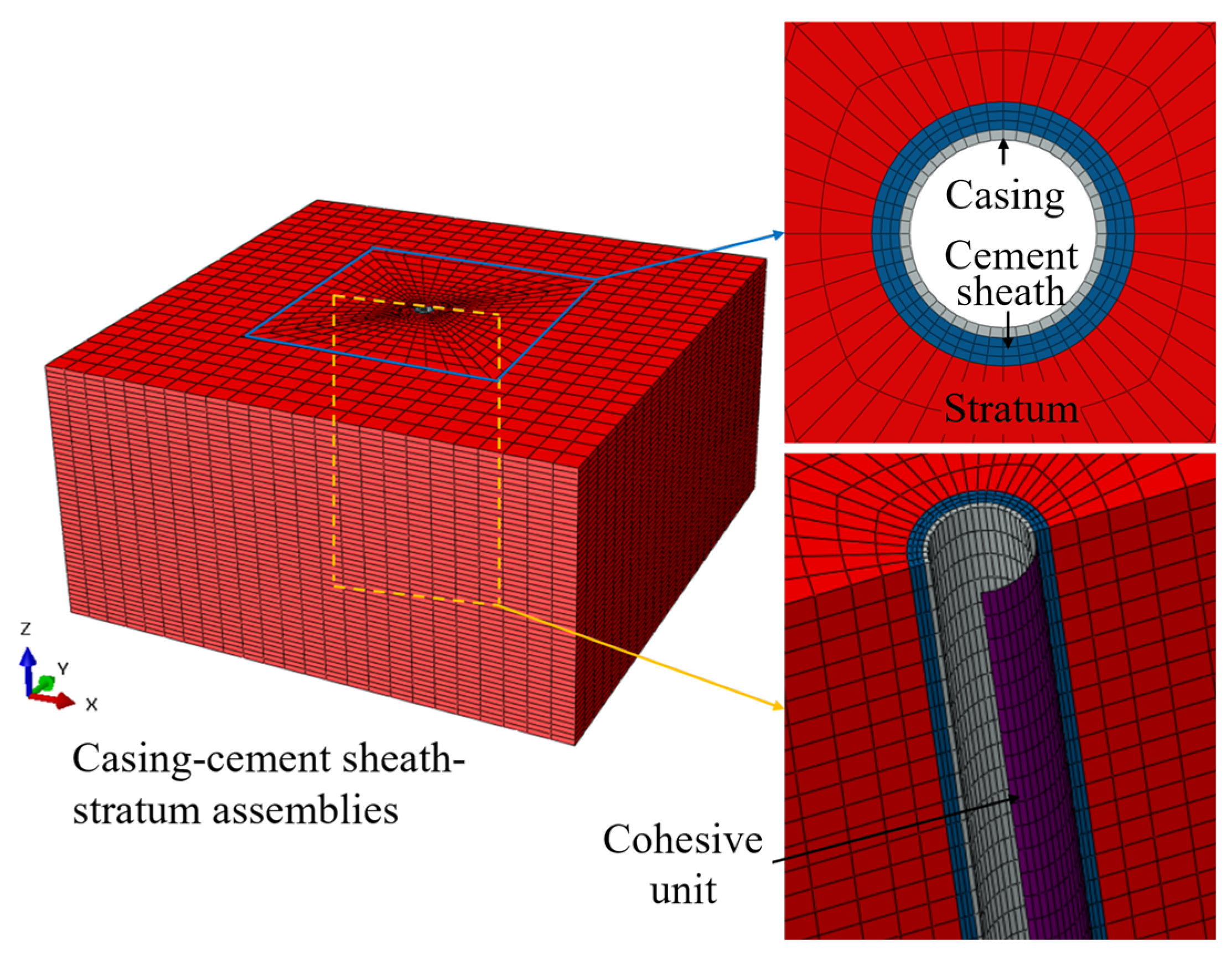
3.5.1. Basic Information on the Finite Element Model

The steam stimulation process consists of three main stages: injection, soaking, and production. In Phase II of the Lvda 5-2 North Oilfield, each steam stimulation cycle features an extended oil production stage with relatively low thermal stress. Therefore, the numerical simulation focuses only on the injection and soaking stages, simulating a 15-day steam injection followed by a 5-day soaking period [60].
The simulation employs a sequential coupling approach to model the steam injection and soaking cycle in two steps. First, it calculates the temperature distribution in the assembled body under cyclic steam stimulation. Then, the temperature results are imported into the stress analysis as predefined fields to obtain the final results. To improve computational efficiency, the model is simplified [1].
(1) The casing remains undeformed and undamaged, the cement sheath is intact or absent, and the borehole shape is regular. (2) The casing, cement sheath, and formation are tightly bonded under initial conditions. (3) There is no slip-induced shear misalignment between formation layers.
Since most casing damage in thermal recovery wells occurs near the insulating packer, we analyze the upper and lower sections of the packer separately. The model’s initial temperature is set to 50 °C. In the upper section, during 350 °C steam injection, heat transfer to the casing is difficult to assess due to the tubing’s insulation. Based on well location, development characteristics, and casing experiments, a 200 °C temperature load is applied to the inner casing wall. During the soaking phase, steam injection stops, and the temperature load is removed. In the lower section, high-temperature steam directly contacts the inner casing wall. Here, the temperature and pressure are assumed to match those of the injected steam. Consequently, the analysis focuses on this section, where a 350 °C temperature load and a uniform internal pressure of 21 MPa are applied to the inner casing wall.
According to St. Venant’s principle, stress distribution is significantly influenced only in the vicinity of the applied load. When the formation width exceeds five times the well diameter, boundary effects can largely be neglected. In this study, a “casing-cement sheath-stratum” assembly is established, as depicted in Figure 10, where the casing is shown in grey, the cement sheath in blue, and the stratum in red.
The dimensions of the stratum model are 10 m, 10 m, and 5 m in the x, y, and z directions, respectively. The formation has an elastic modulus of 6 GPa and a Poisson’s ratio of 0.2. The cement sheath has an outer diameter of 330.48 mm, an inner diameter of 244.48 mm, a height of 5 m, an elastic modulus of 10 GPa, a Poisson’s ratio of 0.19, and a compressive strength of 43.6 MPa. The casing has an outer diameter of 244.48 mm, an inner diameter of 220.5 mm, and a height of 5 m. Its basic parameters are illustrated in Figure 4 and Figure 6. Additional parameters related to the cement sheath, casing, and stratum, which are not included in the basic parameters, are provided in Table 2.

3.5.2. Boundary Conditions

To accurately simulate the cementation state at the interface, a zero-thickness layer of cohesive elements was introduced between the casing and the cement sheath, allowing for the modeling of the cemented interface’s damage process. The interface tensile strength was set at 1.5 MPa, with a shear strength of 3 MPa.
Displacement constraints were applied as follows: the z-direction displacement constraint is fixed at the bottom of the model, the x-direction displacement constraint is enforced on the side perpendicular to the x-axis, and the y-direction displacement constraint is applied to the side perpendicular to the y-axis. Additionally, a horizontal ground stress of 20 MPa, an axial pressure of 50 MPa on the casing, and a cement sheath and formation overburden pressure of 14 MPa are specified.
The casing-cement sheath-stratum assembly model is discretized using hexahedral elements (C3D8R) to balance computational efficiency and solution accuracy. To assess mesh convergence, the mesh density was progressively refined, with a denser mesh near the casing and a coarser mesh toward the stratum. As the total number of elements increased from 4324 to 173,531, the Mises stress in the casing gradually decreased. When the element count reached 64,800 and the total number of nodes was 69,768, the change in Mises stress was less than 3%, indicating that further refinement would not significantly affect the results.

3.5.3. Model Validation

To ensure the reliability of the computational model, the research results of Hou et al. (2024) [31] were selected for finite element model validation in this study. The density of the cement slurry system was set to 1.9 g/cm3. The comparison was conducted under the following conditions: a material temperature of 350 °C, an internal casing pressure of 15 MPa, and a formation pressure of 10 MPa. All other material parameters remained consistent with those in [31]. The casing, cement sheath, and formation dimensions, along with their corresponding stress results, are presented in Table 3. The results indicate that the stress variation trend calculated by this model is generally consistent with the findings of Hou et al. (2024) [31].

4. Results and Discussion

4.1. Analysis of the Upper Well Section Above the Packer

4.1.1. Conventional Straight Well Section

Figure 11a presents the temperature change curves for the casing and cement sheath over time. Shortly after the steam injection begins, the casing temperature quickly rises to 200 °C, with heat then transferring to the cement sheath through conduction. During the soaking phase, the casing temperature gradually decreases, eventually reaching near equilibrium with the cement sheath. By the end of soaking, the casing temperature stabilizes at 96.7 °C. The cement sheath temperature also rises rapidly during continuous steam injection and then levels off, reaching a peak of 178.2 °C by the 15th day.
Figure 11b shows the radial temperature distribution in the conventional straight well section. By the end of steam injection, heat has transferred through the casing to the cement sheath and surrounding formation, with temperature gradually decreasing along the radial direction. At the end of the soaking stage, since no heat is injected during this phase, the wellbore temperature declines as heat continues to dissipate into the formation. Interestingly, some areas of the formation show a temperature increase, indicating ongoing heat exchange within the assembly during the soaking stage. At a boundary 5 m from the wellbore center, the formation temperature remains stable, confirming that the selected model size effectively minimizes the impact of boundary conditions.
Figure 12 shows the Mises stress curve of the casing over time. Due to temperature changes, the casing undergoes thermal expansion and deformation. However, its expansion is constrained by its bond with the surrounding cement sheath, particularly limiting axial elongation. In the conventional straight well section, the maximum Mises stress of 290.7 MPa occurs at the end of the steam injection heating phase. During the soaking stage, the thermal stress within the casing decreases rapidly as the temperature declines. Thanks to the protection of insulated tubing, the thermal stress remains low and does not approach the casing’s yield strength.

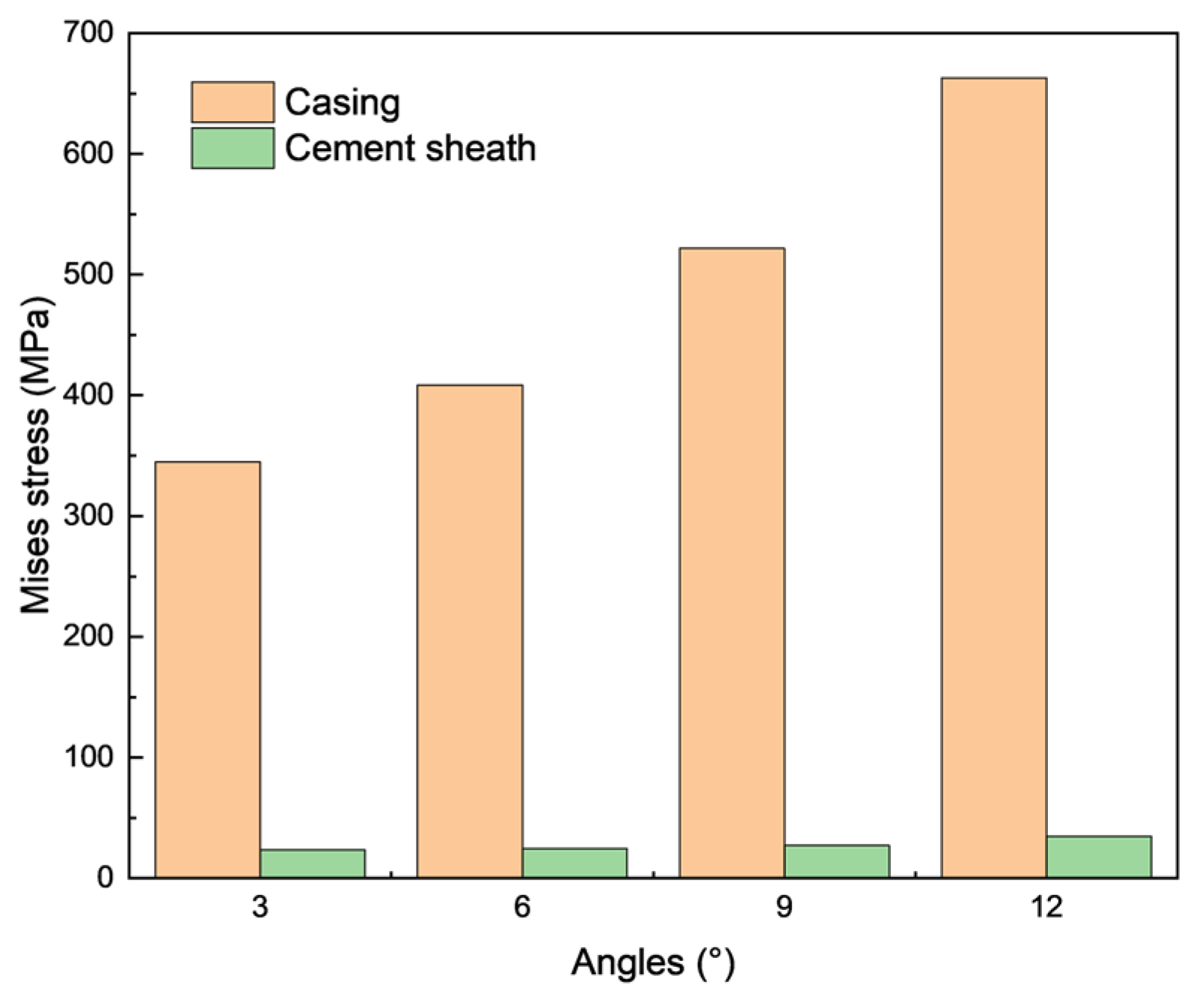
4.1.2. Inclined Well Section

The trajectory of the inclined well section is complex, which amplifies stresses on both the casing and cement sheath at the bend. To assess the impact of the inclined section on the wellbore, a finite element model was developed to analyze the stress state and seal integrity at inclination rates of 3°, 6°, 9°, and 12° per 30 m. Figure 13 illustrates the Mises stress distribution in the casing for each inclination rate. Results indicate that the inclination rate significantly impacts the stresses on the casing and cement sheath. With other factors constant, stress levels in both increase as the inclination angle grows. Compared to the straight section, stress in the inclined section is higher but remains below the casing’s yield strength at this temperature. However, further increases in curvature may push casing stress toward its yield limit. From 3° to 12°, the casing’s Mises stress increases by 92.3%, while the cement sheath’s Mises stress rises by 48.5%. Thus, wellbore designs should minimize steep casing slopes.

4.1.3. Side Drilling Branch Points

After several cycles of thermal recovery, many wells are re-drilled with open-window side drilling to enable further steam throughput and thermal recovery. To analyze this process, a finite element model of the side drilling branch point assembly was developed. For this model, a casing with an outer diameter of 177.8 mm, an inner diameter of 161.7 mm, and a cement sheath thickness of 33 mm was used at the side drilling point. The angle between the branch borehole and the main borehole was set at 30°.
Figure 14 shows the stress distribution around the side drilling branch point. Due to temperature variations and stress concentration, the maximum Mises stress locally reaches 664.8 MPa at the connection between the main casing and the branch (starting point in Figure 14), where yielding is likely. Clockwise along the casing, stress follows a parabolic trend, first decreasing and then increasing. The stress in the lower half of the sidetracking point is lower. The difference between the maximum and minimum stress is 461.5 MPa.

4.2. Analysis of the Well Section Below the Packer

The effects of steam injection pressure, in situ stress, cement elastic modulus, and prestressing on casing performance were analyzed.

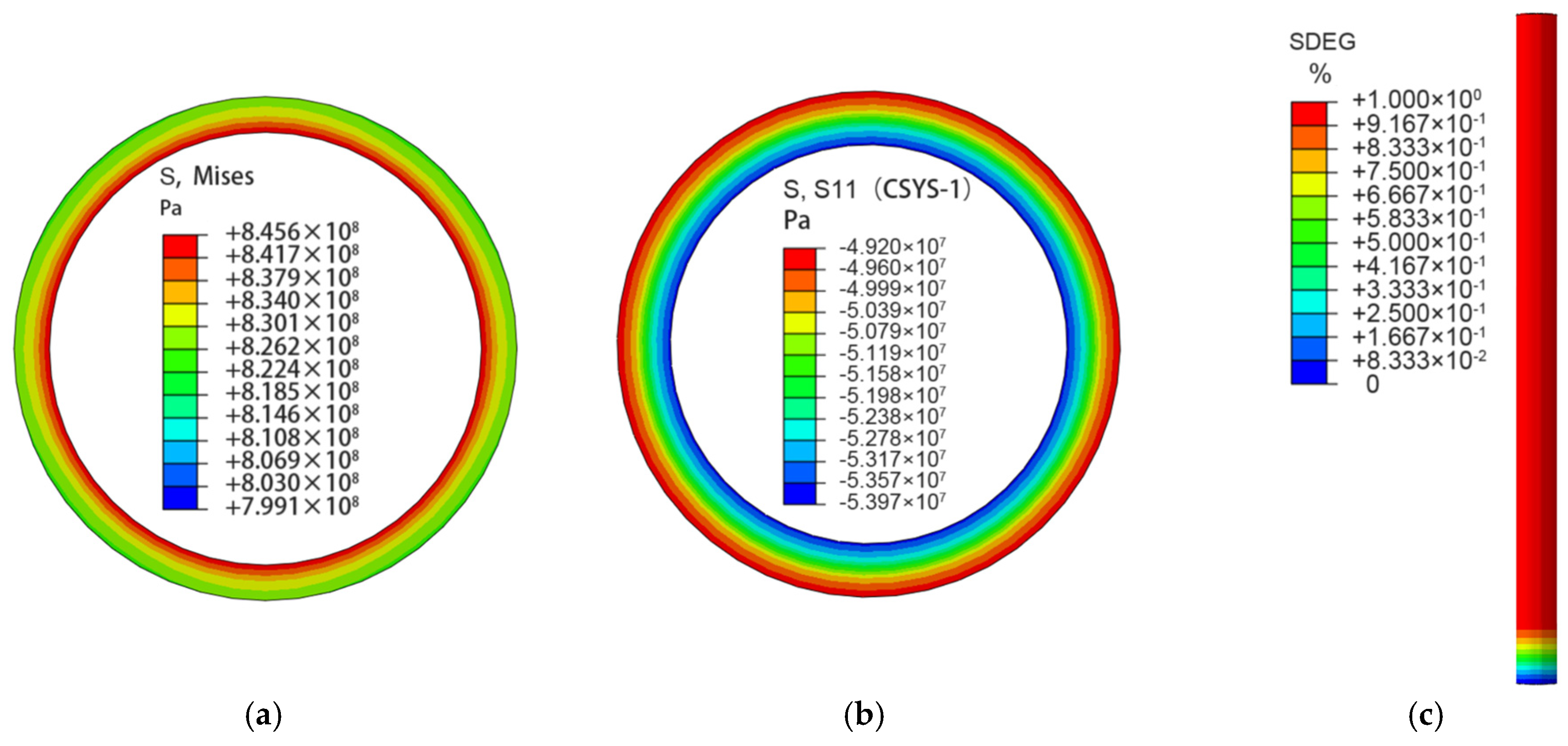
4.2.1. Stress Analysis of Casing and Cement Sheath

Figure 15a presents the Mises stress distribution in the casing during the steam injection phase. The maximum Mises stress in the casing exceeds its yield strength at 350 °C, indicating the onset of plastic strain at this stage. Figure 15b illustrates the stress distribution within the cement sheath in the lower section of the packer. Here, the maximum radial stress in the cement sheath reaches 49.2 MPa, surpassing its compressive strength, resulting in failure due to extrusion and compromising the seal integrity. Figure 15c shows the damage cloud diagram of the “casing-cement sheath” interface in the lower part of the packer. SDEG represents the interface stiffness degradation rate, with damage initiating once the interface stress reaches the threshold for damage. The larger the SDEG value, the more severe the interface damage; when SDEG reaches 1, the interface is fully destroyed. With an interface tensile strength of 2.1 MPa and a shear strength of 4.2 MPa, the interface is nearly completely destroyed.

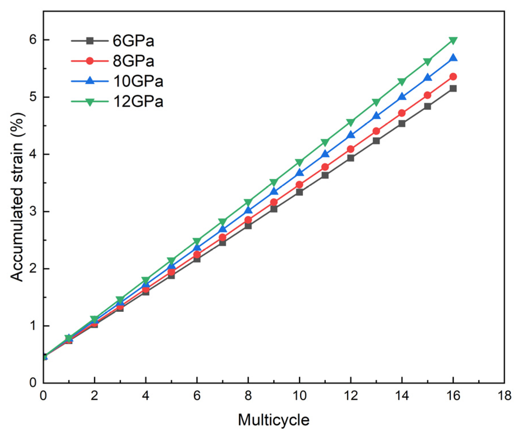
4.2.2. Influence of Steam Injection Pressure

The impact of steam injection pressure (15 MPa, 18 MPa, 21 MPa, and 24 MPa) on casing cumulative strain is presented in Figure 16. The results show a gradual increase in cumulative strain in the casing with each successive steam injection cycle, indicating that once plastic deformation begins, it accumulates progressively with every cycle. Under identical conditions, cumulative strain in the casing decreases as steam injection pressure increases. At a steam injection pressure of 24 MPa, the casing experienced a cumulative strain of 5.2% after 16 rounds of steam injection. According to the industry standard SY/T 6952.2-2013 [61], the safe strain range for TP110H casing is up to 7.2%. After 16 cycles of steam injection at 15 MPa, cumulative casing strain reaches 6.99%, remaining within the safe range, with cumulative strain decreasing at higher steam injection pressures. Therefore, considering both production costs and cyclic oil recovery, increasing steam injection pressure may be advantageous in prolonging the service life of the casing.

4.2.3. Influence of In Situ Stress

Drilling practices reveal that in situ stress distribution is often non-uniform. In this analysis, δ is defined as the ratio of the maximum to the minimum horizontal in situ stress, representing a critical factor influencing the service life of casing in thermal recovery wells. Cumulative strain in the casing was evaluated for δ values of 1.0, 1.2, 1.4, and 1.6. The relationship between in situ stress and cumulative strain in the casing is illustrated in Figure 17.
Figure 17 shows that as δ increases, the casing experiences greater plastic strain per cycle, leading to a higher final cumulative strain. When δ is less than 1.2, the cumulative strain of the casing after 16 steam injection cycles is 6.68%, below the permissible limit of 7.2%, ensuring safety. At δ = 1.4, the casing fails to meet the requirements for 16 cycles, with the cumulative strain reaching 7.4% in the 15th cycle, exceeding the safety limit. When δ reaches 1.6, the cumulative strain approaches the limit at 7.1% after 12 cycles. On average, the cumulative strain increases by 60.9% as δ rises from 1 to 1.6. This indicates that in situ stress distribution significantly increases casing strain, reducing its service life.
To ensure wellbore safety and meet production requirements, it is recommended that when the maximum horizontal in situ stress is assumed to be 20 MPa, the minimum horizontal ground stress should be appropriately increased to maintain a value above 16.6 MPa.

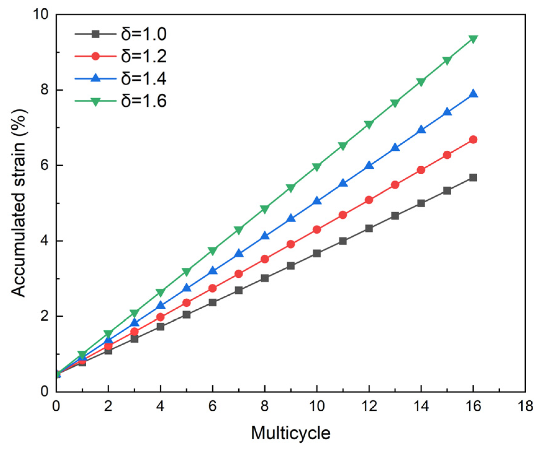
4.2.4. Influence of Cement Elastic Modulus

Once the cement slurry solidifies into a cement sheath, it forms a tight bond with the casing, providing critical support and protection for the casing while ensuring interlayer sealing against formation fluids. To evaluate the effect of the cement elastic modulus on casing strain, cumulative strain was calculated for four different elastic modulus values of the cement sheath: 6 GPa, 8 GPa, 10 GPa, and 12 GPa, as shown in Figure 18.
Figure 18 illustrates that cumulative strain in the casing increases with higher elastic modulus of the cement sheath. Notably, at an elastic modulus of 12 GPa, the casing experiences a cumulative strain of 6.0% after 16 cycles of steam injection, representing a 0.9% increase compared to the 5.1% strain observed at an elastic modulus of 6 GPa. This indicates that a lower elastic modulus for the cement sheath is more favorable for maintaining casing integrity. This is because a cement sheath with a low modulus of elasticity offers greater elastic deformation capacity, allowing it to better accommodate the deformation between the casing and the formation during thermal expansion. This property helps to relieve the stress concentration caused by the difference in thermal expansion during the heavy oil thermal recovery process and optimizes the stress distribution in the wellbore, thus effectively improving the safety and long-term service performance of the casing.

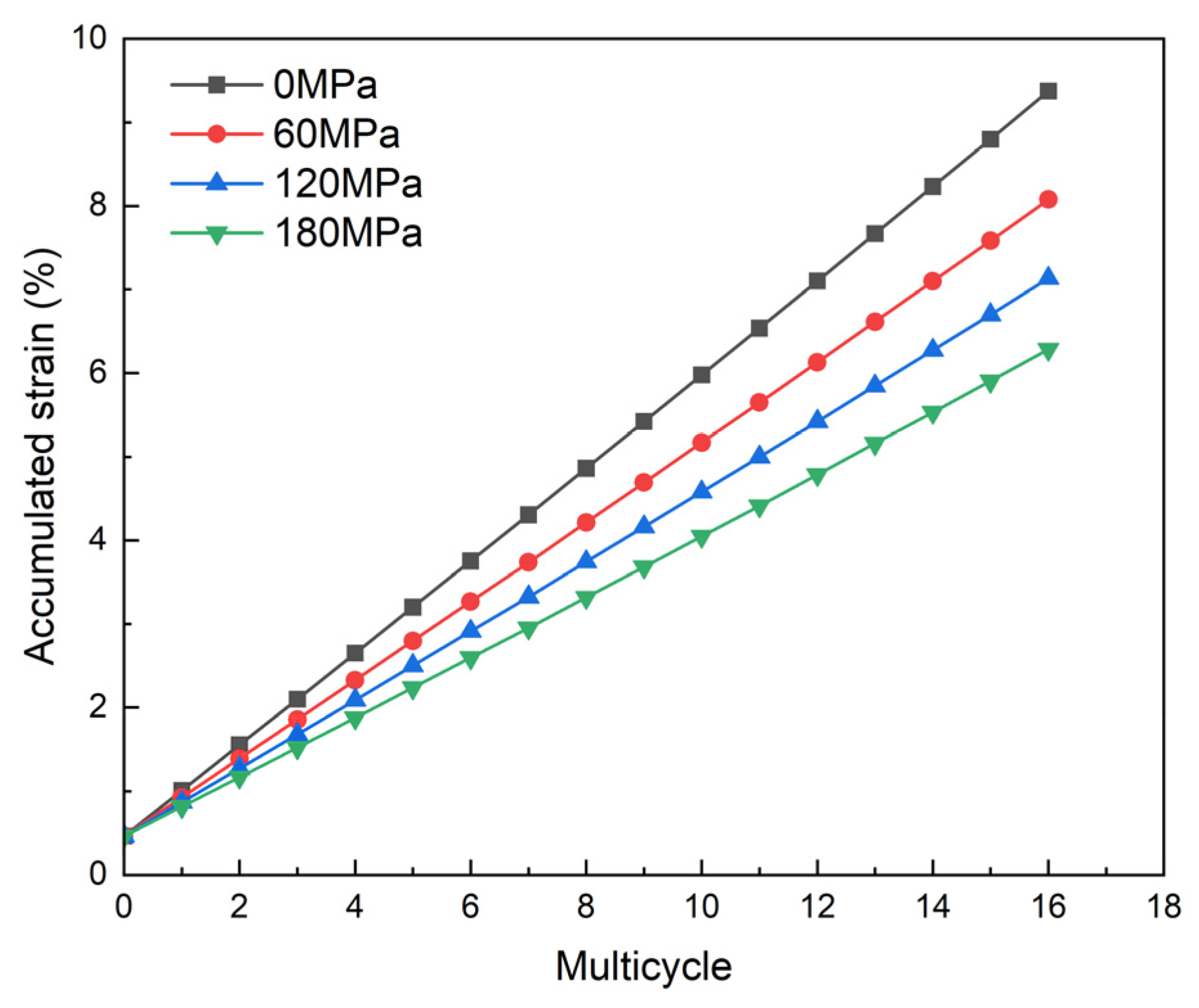
4.2.5. Influence of Prestressing

Lift prestressing cementing technology is commonly employed in heavy oil thermal recovery wells. When δ was set to 1.6 and all other conditions remained constant, prestressing was applied in increments of strength, with the results presented in Figure 19.
As shown in Figure 19, without prestressing, the casing remains safe for up to 12 operational cycles. When prestressing of 60 MPa, 120 MPa, and 180 MPa is applied, the cumulative strain per cycle gradually decreases. The average cumulative strain is reduced by 13.3%, 22.9%, and 31.6%, respectively, and the number of safe service cycles increases to over 14, 16, and 16, respectively.
This demonstrates that lift prestressing cementing technology introduces tensile stress into the casing before steam injection, effectively counteracting part of the axial thermal stress generated during operations. Consequently, this approach significantly reduces damage and extends its service life. To meet the production demand of 16 cycles in the lower well section of the packer, a lifting prestress of 120 MPa is recommended.

5. Conclusions and Future Work

This study investigates the mechanical performance of TP110H casing in thermal recovery wells subjected to multiple high-temperature cycles by mechanical experimentation and simulation. The conclusions are summarized as follows:
(1)
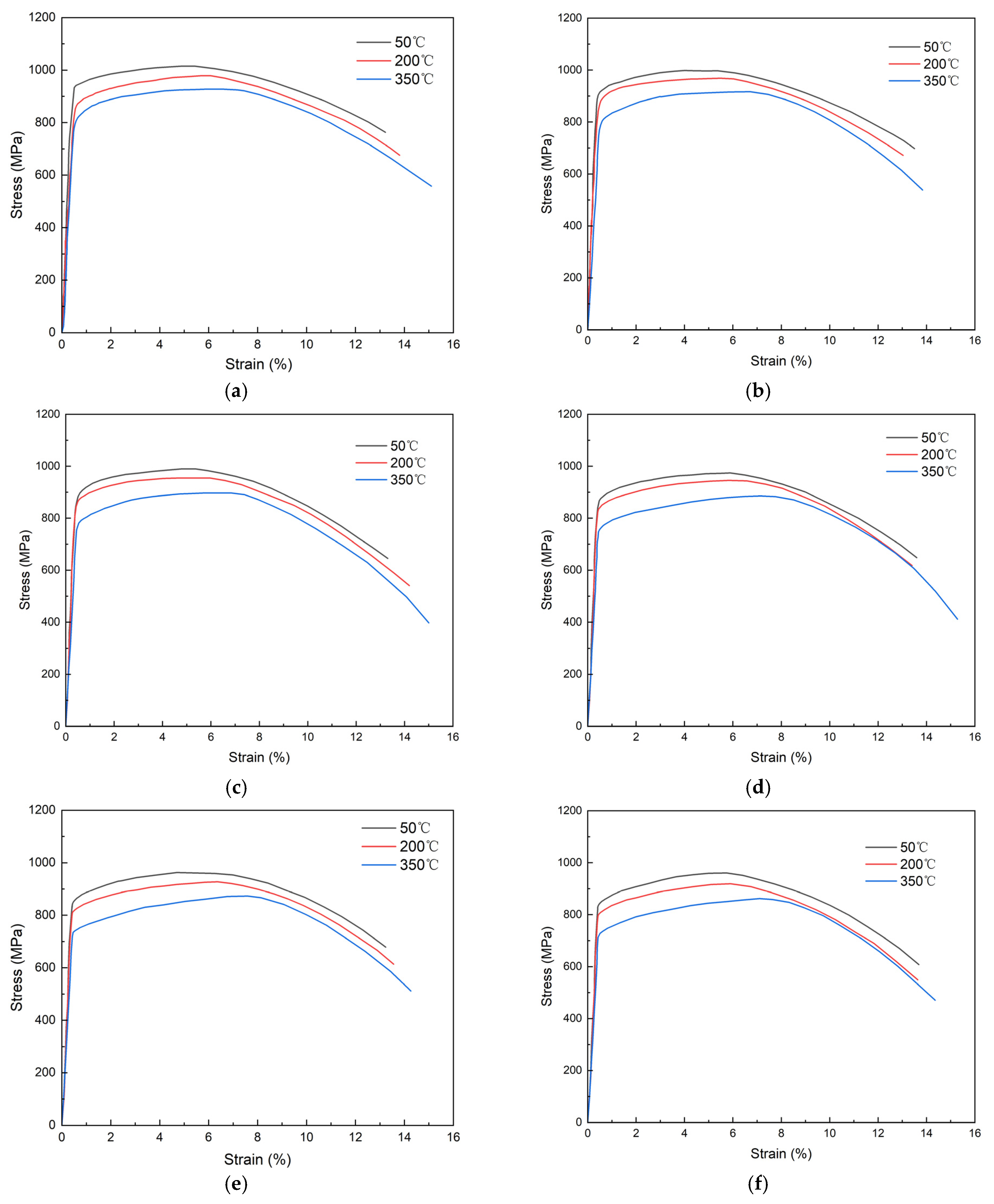
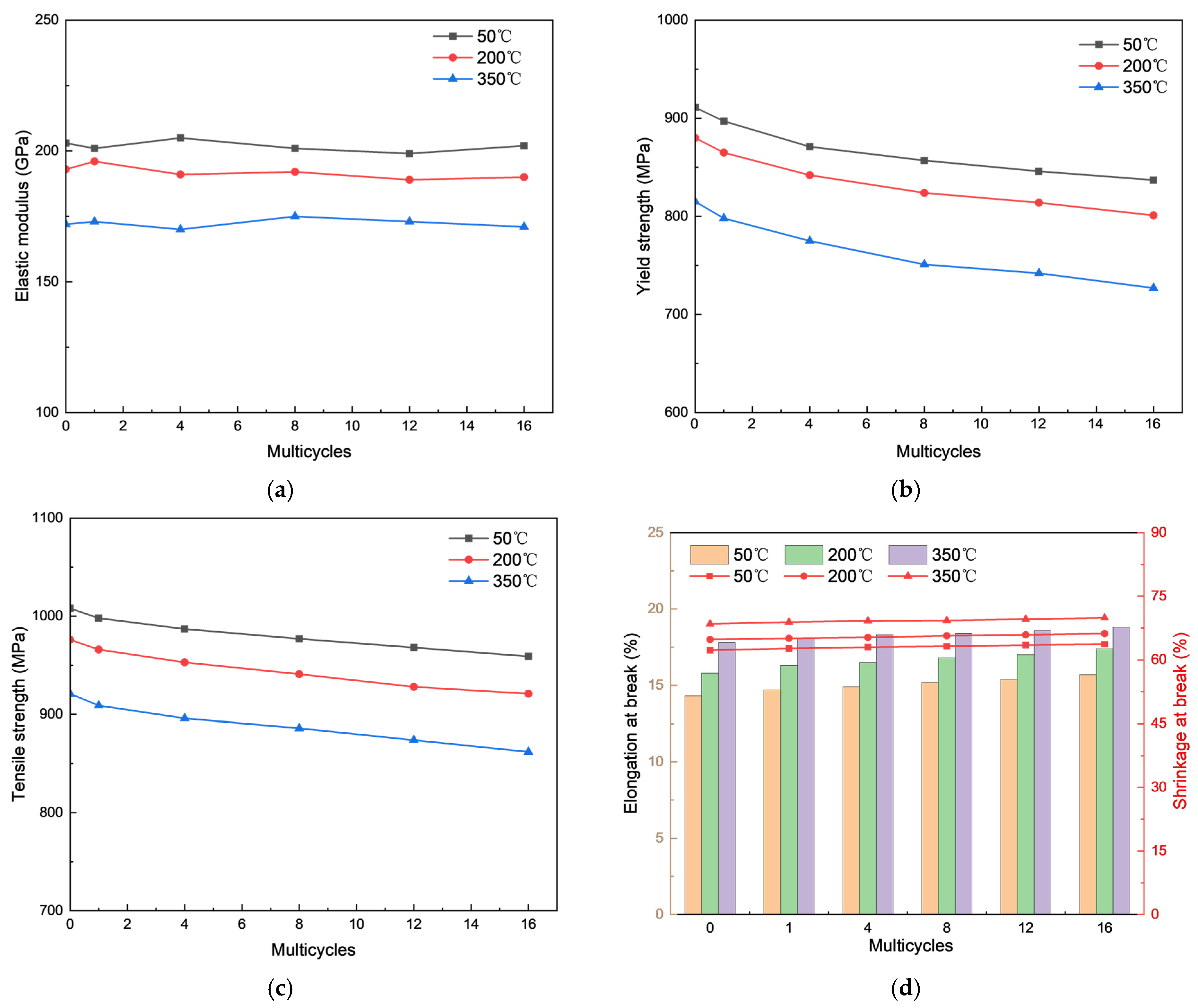
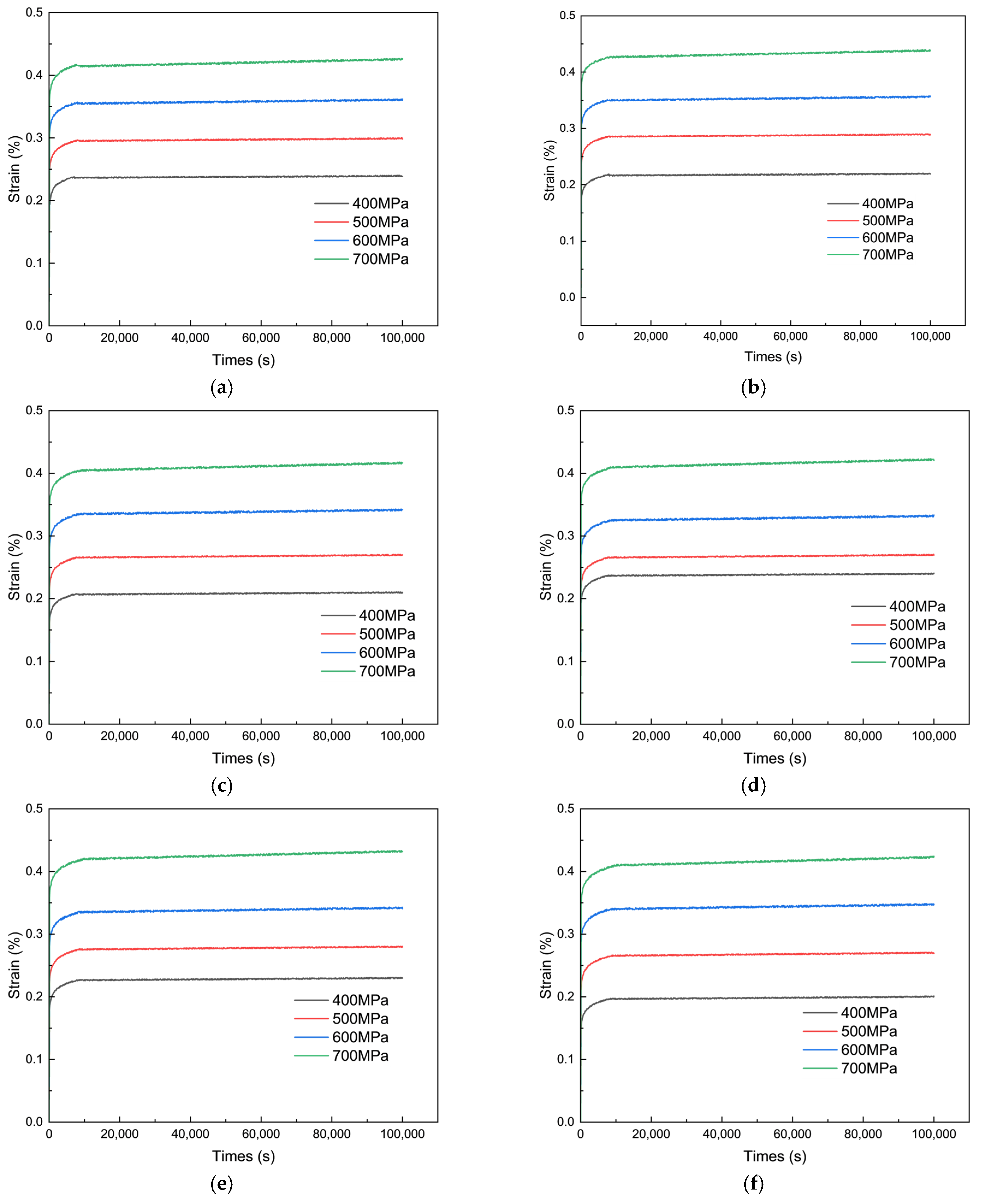
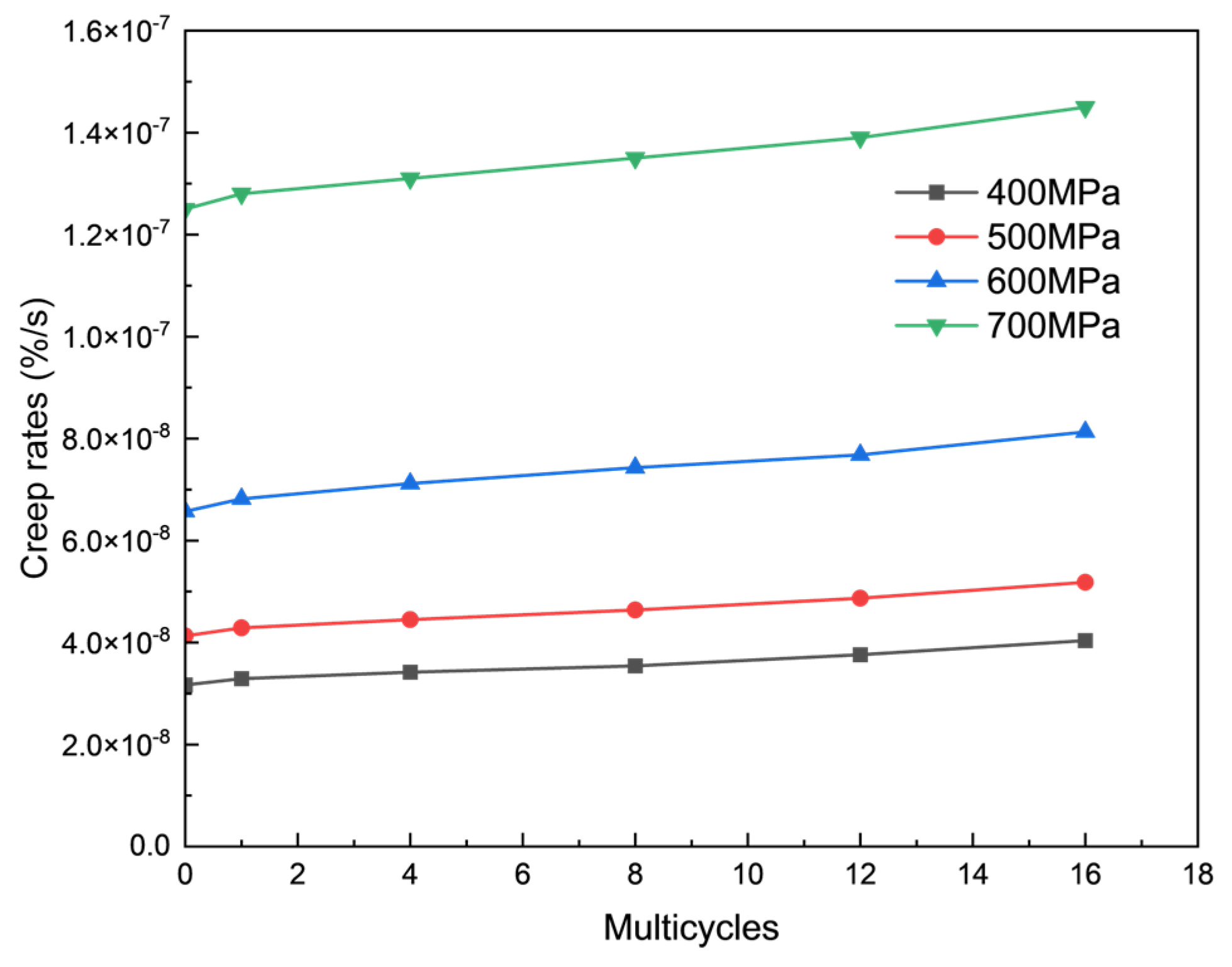
Tensile and creep experiments on TP110H casing indicate that high- and low-temperature cycles significantly degrade casing performance, making their effects essential to consider. Higher temperatures impact casing properties more than thermal cycles. As temperature increases, the elastic modulus, yield strength, and tensile strength decrease, while elongation at break and section shrinkage increase. At 350 °C, after 16 thermal cycles, the elastic modulus, yield strength, and tensile strength decrease by 15.3%, 13.1%, and 10.1%, respectively. In contrast, elongation at break and section shrinkage increase by 18.8% and 69.9%, respectively. Creep rates rise with the number of thermal cycles, especially under higher stress levels (700 MPa), accelerating the process. At 350 °C, after 16 cycles, the maximum creep rate reaches 1.45 × 10⁻⁷%/s.
(2)
Utilizing heat transfer theory, a calculation method for the steam injection process in wellbores is proposed. Furthermore, based on thick-walled cylinder theory and thermoelastic principles, formulas for stress and displacement in the casing-cement sheath-formation system were derived under internal and external pressures as well as thermal loading. These formulas were obtained using individual solutions and finally combined through the superposition principle.
(3)
To simulate the thermally coupled steam injection and soaking cycles in production order, the well section above the packer, equipped with heat-insulating tubing, showed that casing temperatures remained below 200 °C. In the conventional straight, inclined, and side-drilled well sections, both the casing and cement sheath exhibited elastic behavior without plastic deformation. In practice, it is important to minimize the inclined section and to be mindful of the stress concentration effects on the casing around the side-drilling point. The strain design method was used to evaluate casing safety in steam-stimulated thermal recovery wells. Results indicate that TP110H casing can fundamentally meet the production requirements for 16 cycles in the lower section of the packer. Increasing steam injection pressure, using low-modulus cement, and applying prestress lifting can effectively reduce cumulative casing strain, thereby decreasing casing damage rates and extending wellbore service life. However, under conditions of uneven in situ stress, cumulative casing strain rises sharply, significantly impacting casing service life.
(4)
There are several aspects of this study that warrant further investigation, including thermal cycling test parameters, extreme operating conditions, and cement sealing performance. Future research should focus on multi-cycle high- and low-temperature thermal cycling tests and conduct in-depth analyses of the “casing-cement-stratum” system to evaluate cement–casing interface integrity and cement sheath sealing performance under thermal cycling. Additionally, in real-world applications, cementing quality issues—such as casing eccentricity, partial cement loss, and exposure to harsh environments with combined loads and corrosive media—can cause severe wear and corrosion. These pre-existing defects alter wellbore stress conditions and impact the service life of offshore heavy oil thermal recovery wells. Future studies should incorporate these factors to improve the accuracy and practical relevance of research in this field.

Author Contributions

Conceptualization, Y.H.; methodology, Y.H.; software, X.G.; validation, Y.S.; formal analysis, H.L.; investigation, S.H.; resources, S.H.; data curation, Y.S.; writing—original draft, H.L.; writing—review and editing, Y.H.; supervision, Y.S.; funding acquisition, H.L. All authors have read and agreed to the published version of the manuscript.

Funding

This work was funded by the Open Foundation of the Cooperative Innovation Center for Unconventional Oil and Gas, Yangtze University (Ministry of Education of the People’s Republic of China and Hubei Province), (UOGBX2022-05).

Data Availability Statement

The original contributions presented in this study are included in the article. Further inquiries can be directed to the corresponding author.

Acknowledgments

The authors would like to thank the editors and anonymous reviewers for their careful work and thoughtful suggestions that have helped improve this paper substantially.

Conflicts of Interest

The authors declare no conflict of interest.

Glossary

SymbolDefinitionunit
aStratum’s thermal diffusivitym2/d
C1Solution constants
C2Solution constants
EcElastic modulus of the casingPa
FStrain design safety factor
f(t)A time-dependent function of the stratum’s thermal conductivity/
h1Convective heat transfer coefficient between high-temperature steam and the inner pipe wallW/(m2·k)
h2Convective heat transfer coefficient between the annular space and the casing wallW/(m2·k)
h3Radiative heat transfer coefficient between the annular space and the casing wallW/(m2·k)
kAThermal conductivity of the tubingW/(m·k)
kBThermal conductivity of the insulationW/(m·k)
kCThermal conductivity of the casingW/(m·k)
kDThermal conductivity of the cement sheath W/(m·k)
kEThermal conductivity of the stratumW/(m·K)
LVertical depthm
p1Internal pressure on the casing’s inner wallPa
p2Contact pressure between the casing and the cement sheathPa
RTotal thermal resistanceK/W
r1Inner radius of the inner pipem
r2Outer radius of the inner pipem
r3Inner radius of the outer pipem
r4Outer radius of the outer pipem
riInner radius of the casing m
roOuter radius of the casingm
rhOuter radius of the cement sheathm
TRadial temperature distribution function within the cylinder°C
T0Mean annual surface temperature °C
TsInjected steam temperature °C
ThCement sheath’s outer boundary temperature°C
tSteam injection durationdays
urRadial displacement of the casing under internal and external pressurem
αTgeothermal gradient °C/m
σrRadial stress of the casing under internal and external pressurePa
σθCircumferential stress of the casing under internal and external pressurePa
αLinear thermal expansion coefficient of the material°C−1
μcPoisson’s ratio of the casing
δ Uniform elongation of the casing%
ε Cumulative strain in the casing%
ε i Cumulative strain increment in the casing after the i-th cycle%
ε Permissible strain of the casing%

References

  1. Han, X.; Feng, F.; Zhang, J. Study on the Whole Life Cycle Integrity of Cement Interface in Heavy Oil Thermal Recovery Well under Circulating High Temperature Condition. Energy 2023, 278, 127873. [Google Scholar] [CrossRef]
  2. Haugan, J.A.; Jenssen, E.S.; Hatlem, S. Challenges in Heavy Crude Oil-Grane, an Overview. In Proceedings of the Offshore Technology Conference, Houston, TX, USA, 1–4 May 2006. [Google Scholar]
  3. Hein, F.J. Heavy Oil and Oil (Tar) Sands in North America: An Overview & Summary of Contributions. Nat. Resour. Res. 2006, 15, 67–84. [Google Scholar] [CrossRef]
  4. Omoregbe, O.; Hart, A. Global Trends in Heavy Oil and Bitumen Recovery and In-Situ Upgrading: A Bibliometric Analysis during 1900–2020 and Future Outlook. J. Energy Resour. Technol. 2022, 144, 123007. [Google Scholar] [CrossRef]
  5. Trindade, W.L.; Branco, C.C.M. The Offshore Heavy Oil Development Challenges in Brazil. In Proceedings of the SPE Latin American and Caribbean Petroleum Engineering Conference, Rio de Janeiro, Brazil, 20 June 2005; SPE: Rio de Janeiro, Brazil, 2005; p. SPE-97381-MS. [Google Scholar]
  6. Sun, H.; Wang, H.; Cao, X.; Shu, Q.; Fan, Z.; Wu, G.; Yang, Y.; Wu, Y. Innovations and Applications of the Thermal Recovery Techniques for Heavy Oil. Energy Geosci. 2024, 5, 100332. [Google Scholar] [CrossRef]
  7. Cui, G.; Niu, Z.; Hu, Z.; Feng, X.; Chen, Z. The Production Analysis and Exploitation Scheme Design of a Special Offshore Heavy Oil Reservoir—First Offshore Artificial Island with Thermal Recovery. J. Mar. Sci. Eng. 2024, 12, 1186. [Google Scholar] [CrossRef]
  8. Wang, L.; Guo, J.; Li, C.; Xiong, R.; Chen, X.; Zhang, X. Advancements and Future Prospects in In-Situ Catalytic Technology for Heavy Oil Reservoirs in China: A Review. Fuel 2024, 374, 132376. [Google Scholar] [CrossRef]
  9. Li, Y.; Qian, Y.; Lu, H.; Dai, P.; Zhu, H.; Yang, Q.; Liu, Y. High-Efficiency Pre-Treatment Core Tube for Produced Water in the Main Cavity Coupled with Secondary Cavities and Its Application in the Bohai Heavy Oilfield. J. Mar. Sci. Eng. 2023, 11, 93. [Google Scholar] [CrossRef]
  10. Liu, Y.; Zou, J.; Meng, X.; Zhou, F.; Liu, H.; Wang, Q.; Qi, Z.; Fan, J. Experimental Study on Horizontal-Well Multi-Thermal Fluid Stimulation Process in Offshore Heavy Oil Reservoirs. J. Pet. Explor. Prod. Technol. 2020, 10, 3057–3068. [Google Scholar] [CrossRef]
  11. Temizel, C.; Canbaz, C.H.; Tran, M.; Abdelfatah, E.; Jia, B.; Putra, D.; Irani, M.; Alkouh, A. A Comprehensive Review Heavy Oil Reservoirs, Latest Techniques, Discoveries, Technologies and Applications in the Oil and Gas Industry. In Proceedings of the PE International Heavy Oil Conference and Exhibition, Roma, Italy, 10 December 2018; SPE: Kuwait City, Kuwait, 2018; p. D012S024R001. [Google Scholar]
  12. Tan, J.; Wang, Z.; Chen, S.; Hu, H. Progress and Outlook of Supercritical CO2 —Heavy Oil Viscosity Reduction Technology: A Minireview. Energy Fuels 2023, 37, 11567–11583. [Google Scholar] [CrossRef]
  13. Zhao, F.; Liu, Y.; Lu, N.; Xu, T.; Zhu, G.; Wang, K. A Review on Upgrading and Viscosity Reduction of Heavy Oil and Bitumen by Underground Catalytic Cracking. Energy Rep. 2021, 7, 4249–4272. [Google Scholar] [CrossRef]
  14. Guo, K.; Li, H.; Yu, Z. In-Situ Heavy and Extra-Heavy Oil Recovery: A Review. Fuel 2016, 185, 886–902. [Google Scholar] [CrossRef]
  15. Yang, M.; Chai, M.; Yuan, S.; Feng, T.; Wang, S.; Zhang, J.; Feng, Q.; Chen, Z.; Wei, T.; Wu, G.; et al. In-Situ Combustion for Heavy Oil and Oil Sands Recovery: Recent Progress, Field Applications, and Future Perspectives. Energy Fuels 2024, 38, 10395–10420. [Google Scholar] [CrossRef]
  16. Telmadarreie, T.; Berton, P.; Bryant, S.L. Treatment of Water-in-Oil Emulsions Produced by Thermal Oil Recovery Techniques: Review of Methods and Challenges. Fuel 2022, 330, 125551. [Google Scholar] [CrossRef]
  17. Dong, X.; Liu, H.; Chen, Z.; Wu, K.; Lu, N.; Zhang, Q. Enhanced Oil Recovery Techniques for Heavy Oil and Oilsands Reservoirs after Steam Injection. Appl. Energy 2019, 239, 1190–1211. [Google Scholar] [CrossRef]
  18. Neshat Ghojogh, J.; Noruzi-Masir, B.; Bakhshi, P.; Keyvan, P.; Salehipour-Bavarsad, A. Application of Horizontal Wells for Cyclic Steam Stimulation (CSS) in Bitumen Recovery: Production Optimization through Reservoir Simulation. Arab. J. Geosci. 2020, 13, 150. [Google Scholar] [CrossRef]
  19. Xu, A.Z.; Wu, X.H.; Fan, Z.F.; Zhao, L.; Wang, C.G. Improvements of Superheated Steam Stimulation in Secondary Development of Heavy Oil Reservoir. Adv. Mater. Res. 2012, 524–527, 1450–1455. [Google Scholar] [CrossRef]
  20. Gil′manov, A.Y.; Shevelev, A.P.; Lagunov, P.S.; Gulyaev, P.N.; Petukhov, A.S.; Lyutoev, P.A. Influence of the Thermophysical Properties of the Reservoir and Fluid on the Technological Parameters of the Cyclic Steam Stimulation. J. Eng. Phys. Thermophys. 2023, 96, 1311–1319. [Google Scholar] [CrossRef]
  21. Gil’manov, Y.A.; Arazov, A.R.; Shevelyov, A.P. Influence of Convective Processes on Technological Parameters of Cyclic Steam Stimulation of Oil Reservoirs. J. Eng. Phys. Thermophys. 2022, 95, 1172–1179. [Google Scholar] [CrossRef]
  22. Bao, Y.; Wang, J.; Gates, I.D. On the Physics of Cyclic Steam Stimulation. Energy 2016, 115, 969–985. [Google Scholar] [CrossRef]
  23. Pratama, R.A.; Babadagli, T. A Review of the Mechanics of Heavy-Oil Recovery by Steam Injection with Chemical Additives. J. Pet. Sci. Eng. 2022, 208, 109717. [Google Scholar] [CrossRef]
  24. Hein, F.J. Geology of Bitumen and Heavy Oil: An Overview. J. Pet. Sci. Eng. 2017, 154, 551–563. [Google Scholar] [CrossRef]
  25. He, C.; Xu, A.; Fan, Z.; Zhao, L.; Bo, B. A New Mathematical Model For Heat Radius of Cyclic Superheated Steam Stimulation with Horizontal Wellbore. Math. Probl. Eng. 2018, 2018, 7601702. [Google Scholar] [CrossRef]
  26. Li, Z. Casing Cementing with Half Warm-up for Thermal Recovery Wells. J. Pet. Sci. Eng. 2008, 61, 94–98. [Google Scholar] [CrossRef]
  27. Geng, L.; Liu, D.; Han, L.; Feng, S. Numerical Analysis of Casing Damage in Heavy Oil Thermal Recovery Wells. IOP Conf. Ser. Earth Environ. Sci. 2021, 726, 012011. [Google Scholar] [CrossRef]
  28. Loiseau, A. Thermal Expansion of Cement and Well Integrity of Heavy Oil Wells. In Proceedings of the PE Latin America and Caribbean Heavy and Extra Heavy Oil Conference, Medellin, Colombia, 24 September 2014; SPE: Medellín, Colombia, 2014; p. D011S004R003. [Google Scholar]
  29. Wang, Z.; Wen, Y.; Li, Y.; Wang, J.; Liu, W. Effect of Poroelasticity on the Integrity of Cement Sheath in Heavy Oil Wells. Chem. Technol. Fuels Oils 2022, 58, 851–861. [Google Scholar] [CrossRef]
  30. Zhu, X.; Liu, S.; Tong, H. Plastic Limit Analysis of Defective Casing for Thermal Recovery Wells. Eng. Fail. Anal. 2013, 27, 340–349. [Google Scholar] [CrossRef]
  31. Hou, D.; Zhang, Z.; Geng, Y.; Yue, J.; Wu, Z. Study on Channeling-Leakage Pressure of Casing-Cement Sheath-Stratum Assembly in Thermal Recovery Wells. Fuel 2024, 356, 129592. [Google Scholar] [CrossRef]
  32. Li, F.; Yan, W.; Kong, X.; Li, J.; Zhang, W.; Kang, Z.; Yang, T.; Tang, Q.; Wang, K.; Tan, C. Study on Multi-Factor Casing Damage Prediction Method Based on Machine Learning. Energy 2024, 296, 131044. [Google Scholar] [CrossRef]
  33. Wang, H.; Li, M.; Zhao, Q.; Hao, W.; Zhang, H.; Li, Y.; Huang, P.; Zou, Y. Study on Casing Safety Evaluation in High-Temperature Wells with Annular Pressure Buildup. Processes 2023, 11, 1915. [Google Scholar] [CrossRef]
  34. Xu, J.; Deng, J.; Chen, Y.; Jia, L.; Xiao, Y.; Liu, W. Analysis of Casing Instability and Factors Influencing It in Thermal Production Oil Wells. Chem. Technol. Fuels Oils 2021, 57, 804–812. [Google Scholar] [CrossRef]
  35. Choi, W.; Fujiyama, K.; Kim, B.; Song, G. Development of Thermal Stress Concentration Factors for Life Assessment of Turbine Casings. Int. J. Press. Vessel. Pip. 2012, 98, 1–7. [Google Scholar] [CrossRef]
  36. Xu, A.; Mu, L.; Fan, Z.; Wu, X.; Zhao, L.; Bo, B.; Xu, T. Mechanism of Heavy Oil Recovery by Cyclic Superheated Steam Stimulation. J. Pet. Sci. Eng. 2013, 111, 197–207. [Google Scholar] [CrossRef]
  37. Hua, W.; Michael, F.; Aimé, F. Assessing Leak Paths in the Cement Sheath of a Cased Borehole by Analysis of Monopole Wavefield Modes. Commun. Comput. Phys. 2020, 28, 424–441. [Google Scholar] [CrossRef]
  38. Ji, Y.; Xu, H.; Zhang, J.; Guo, L. Analytical Modeling on the Geo-Stress and Casing Damage Prevention with the Thermo-Hydro-Mechanical (THM) Coupling of Multi-Field Physics. J. Therm. Anal. Calorim. 2020, 139, 2719–2737. [Google Scholar] [CrossRef]
  39. Shi, J.; Zhang, Q.; Lian, Z.; Ding, L.; Wan, Z. A Calculation Method for Ultimate and Allowable Loads in High-Pressure Thick-Walled Worn Casing. Ocean Eng. 2024, 313, 119448. [Google Scholar] [CrossRef]
  40. Gruben, G.; Dillingh, B.; Kaldal, G.S.; Hoang, N.-H.; Wollenweber, J.; Rørvik, G.; Thorbjornsson, I.; Nyhus, B. Thermo-Mechanical Tensile Testing of Geothermal Casing Materials. Geothermics 2021, 89, 101944. [Google Scholar] [CrossRef]
  41. Peng, J.; Li, R. Implementation of Method a in GB/T 228.1-2010 by Using Crosshead Displacement Rate. Phys. Test. Chem. Anal. Part A: Phys. Test. 2021, 57, 19–21+24. [Google Scholar]
  42. GB/T 34907-2017; Technical Specifications and Fitness for Service Evaluation Method for Thermal Well Casing under Cyclic Steam Stimulation Process. General Administration of Quality Supervision, Inspection and Quarantine of the People’s Republic of China: Beijing, China, 2017.
  43. Liu, W.; Zhou, Z.; Li, Z.; Li, M.; Li, Q.; Ye, Z.; Yao, J.; Zhong, X. The High-Temperature Mechanical Properties of HS110S Steel and Its Corrosion Behaviors in Harsh Downhole Environment. Anti Corros. Methods Mater. 2022, 69, 550–560. [Google Scholar] [CrossRef]
  44. Pang, Z.; Wang, X.; Zhang, F.; Ge, T.; Wang, D.; Zhang, C.; Liu, D. The Study on Classification Methods for Low Production Wells of Thermal Recovery and Its Applications. J. Pet. Explor. Prod. Technol. 2019, 9, 469–481. [Google Scholar] [CrossRef]
  45. Malozyomov, B.V.; Martyushev, N.V.; Kukartsev, V.V.; Tynchenko, V.S.; Bukhtoyarov, V.V.; Wu, X.; Tyncheko, Y.A.; Kukartsev, V.A. Overview of Methods for Enhanced Oil Recovery from Conventional and Unconventional Reservoirs. Energies 2023, 16, 4907. [Google Scholar] [CrossRef]
  46. Mokheimer, E.M.A.; Hamdy, M.; Abubakar, Z.; Shakeel, M.R.; Habib, M.A.; Mahmoud, M. A Comprehensive Review of Thermal Enhanced Oil Recovery: Techniques Evaluation. J. Energy Resour. Technol. 2019, 141, 030801. [Google Scholar] [CrossRef]
  47. Wang, S.; Chen, X.; He, M.; Xu, M.; Dai, B. Coupled Modeling Circulating Multi-Layer Wellbore Temperature and Stress Field during Deepwater High-Temperature and High-Pressure Gas Well Testing. Therm. Sci. Eng. Prog. 2024, 47, 102356. [Google Scholar] [CrossRef]
  48. Brown, C.S.; Falcone, G. Investigating Heat Transmission in a Wellbore for Low-Temperature, Open-Loop Geothermal Systems. Therm. Sci. Eng. Prog. 2024, 48, 102352. [Google Scholar] [CrossRef]
  49. Gu, H.; Cheng, L.; Huang, S.; Li, B.; Shen, F.; Fang, W.; Hu, C. Steam Injection for Heavy Oil Recovery: Modeling of Wellbore Heat Efficiency and Analysis of Steam Injection Performance. Energy Convers. Manag. 2015, 97, 166–177. [Google Scholar] [CrossRef]
  50. Fuentes-Ibarra, D.; Cazarez-Candia, O.; Aguilar-Madera, C.G. Local Thermal Equilibrium Constraints for Energy Transport Equations for Thermal Oil Recovery Processes. Int. J. Therm. Sci. 2024, 197, 108782. [Google Scholar] [CrossRef]
  51. Kolawole, F.; Evenick, J.C. Global Distribution of Geothermal Gradients in Sedimentary Basins. Geosci. Front. 2023, 14, 101685. [Google Scholar] [CrossRef]
  52. Hasan, A.R.; Kabir, C.S.; Wang, X. Wellbore Two-Phase Flow and Heat Transfer during Transient Testing. SPE J. 1998, 3, 174–180. [Google Scholar] [CrossRef]
  53. Li, P.; Wang, X.; Zhang, Y. Thermal Recovery of Heavy Oil Reservoirs: Modeling of Flow and Heat Transfer Characteristics of Superheated Steam in Full-Length Concentric Dual-Tubing Wells. Geoenergy Sci. Eng. 2025, 244, 213432. [Google Scholar] [CrossRef]
  54. Zhang, L.; Zhang, L.; Liang, W. Casing Safety Evaluation for Setting Liner Hanger. J. Nat. Gas Sci. Eng. 2014, 19, 58–61. [Google Scholar] [CrossRef]
  55. Jiang, X.; Dong, X.; Xu, W.; Liu, H.; Chen, Z. Mathematical Modeling for the Production Performance of Cyclic Multi-Thermal Fluid Stimulation Process in Layered Heavy Oil Reservoirs. Geoenergy Sci. Eng. 2024, 243, 213350. [Google Scholar] [CrossRef]
  56. Han, L.; Wang, H.; Wang, J.; Xie, B.; Tian, Z.; Wu, X. Strain-Based Casing Design for Cyclic-Steam-Stimulation Wells. SPE Prod. Oper. 2018, 33, 409–418. [Google Scholar] [CrossRef]
  57. Lihong, H.; Jianjun, W.; Hang, W.; Changyi, Q.; Yaorong, F.; Bin, X.; Xuelu, Z.; Zhihua, T. Strain Based Design and Material Selection Technology for Thermal Well Casing. In Proceedings of the International Petroleum Technology Conference, Beijing, China, 26 March 2013; IPTC: Beijing, China, 2013; p. IPTC-16739-Abstract. [Google Scholar]
  58. Wang, J.; Li, D.; Du, X.; Li, H.; Yang, S. Development of a Design Method for Casing and Tubing Strings under Complex Alternating Loads. Processes 2023, 11, 2582. [Google Scholar] [CrossRef]
  59. Han, L.; Wang, H.; Wang, J.; Zhu, L.; Xie, B.; Tian, Z. Strain Based Design and Field Application of Thermal Well Casing String for Cyclic Steam Stimulation Production. In Proceedings of the SPE Canada Heavy Oil Conference, Calgary, AB, Canada, 7 June 2016; SPE: Calgary, AB, Canada, 2016; p. D011S001R003. [Google Scholar]
  60. Zhang, J. Performance of High Temperature Steam Injection in Horizontal Wells of Heavy Oil Reservoirs. Energy 2023, 282, 128863. [Google Scholar] [CrossRef]
  61. Tang, K.; Wang, X.; Peng, J.; Yang, H.; Zhang, Y. Development of Grade 110SH-1 Thermal Recovery Casing for Heavy Oil Thermal Recovery Well. Steel Specif. 2020, 41, 43–47. [Google Scholar] [CrossRef]
Figure 1. Thermal cycling experimental setup: (a) TP110H casing; (b) temperature control system.
Jmse 13 00597 g001
Figure 2. High-temperature tensile experiment: (a) experiment specimen size; (b) the specimen before the experiment; (c) tensile testing machine; (d) the specimen after the experiment.
Jmse 13 00597 g002
Figure 3. Tensile stress–strain curves of TP110H steel after various thermal cycles: (a) no thermal cycling; (b) 1 cycle; (c) 4 cycles; (d) 8 cycles; (e) 12 cycles; (f) 16 cycles.
Jmse 13 00597 g003
Figure 4. Mechanical properties of TP110H steel after various thermal cycles: (a) elastic modulus; (b) yield strength; (c) tensile strength; (d) elongation and shrinkage at break.
Jmse 13 00597 g004
Figure 5. Creep–strain curves of TP110H steel after various thermal cycles: (a) no thermal cycling; (b) 1 cycle; (c) 4 cycles; (d) 8 cycles; (e) 12 cycles; (f) 16 cycles.
Jmse 13 00597 g005
Figure 6. Influence of thermal cycle rounds and load on creep rate of TP110H steel.
Jmse 13 00597 g006
Figure 7. Schematic of the thermal recovery well structure.
Jmse 13 00597 g007
Figure 8. Wellbore heat transfer for steam injection process.
Jmse 13 00597 g008
Figure 9. Schematic force diagram of the casing-cement sheath-stratum combination: (a) under applied pressure; (b) under thermal stress.
Jmse 13 00597 g009
Figure 10. Assemble geometry.
Jmse 13 00597 g010
Figure 11. Variation in temperature during steam injection and soaking stages: (a) casing and cement sheath temperature profiles over time; (b) radial temperature distribution profile of the assembly.
Jmse 13 00597 g011
Figure 12. Casing stress curve over time.
Jmse 13 00597 g012
Figure 13. Mises stress in the casing at different inclination angles.
Jmse 13 00597 g013
Figure 14. Mises stress in the casing around the side drilling point.
Jmse 13 00597 g014
Figure 15. Casing and cement sheath stresses: (a) casing Mises stress; (b) cement sheath radial stress; (c) damage maps at the casing-cement sheath interface.
Jmse 13 00597 g015
Figure 16. Effect of steam injection pressure on the cumulative strain of casing.
Jmse 13 00597 g016
Figure 17. Effect of in situ stress on cumulative strain of casing.
Jmse 13 00597 g017
Figure 18. Effect of cement elastic modulus on cumulative strain of casing.
Jmse 13 00597 g018
Figure 19. Effect of prestress on the cumulative strain of casing.
Jmse 13 00597 g019
Table 1. Reduction in yield and tensile strength of TP110H casing after high-temperature thermal cycling (compared to no cycling).
TemperatureNumber of Thermal CyclesYield Strength
/%
Tensile Strength
/%
GB/T 34907-2017 Permissible Strength Limits/%Assessment Results
5011.51.020Compliance
44.42.120Compliance
85.93.120Compliance
127.14.020Compliance
168.14.920Compliance
20011.71.020Compliance
44.32.420Compliance
86.43.620Compliance
127.54.920Compliance
169.05.620Compliance
35012.11.320Compliance
44.92.720Compliance
87.93.820Compliance
129.05.120Compliance
1610.86.420Compliance
Table 2. Material thermodynamic parameters.
MaterialsDensity
kg/m3
Expansion Coefficient
10−5/°C
Specific Heat Capacity
J/kg/°C
Thermal Conductivity
W/m/°C
Casing78001.3646046.0
Cement sheath19001.108370.98
Stratum23001.038961.6
Table 3. Comparison of calculation results.
AssembliesOuter Diameter/mmWall Thickness/mmInner Diameter/mmStress/MPa
Wellbore in Reference [31]Casing24611.522315.18–131.74
Cement-sheath31132.52461.72–9.35
stratum389403091.66–37.35
Model in Reference [31]Casing114.36.6101.115.54–116.33
Cement-sheath164.325114.31.69–9.03
stratum206.321164.32.27–43.08
Model in this studyCasing244.4811.99220.514.98–136.46
Cement-sheath330.48 43244.481.71–9.51
stratum10,0004834.76330.48 0.94–32.03
Disclaimer/Publisher’s Note: The statements, opinions and data contained in all publications are solely those of the individual author(s) and contributor(s) and not of MDPI and/or the editor(s). MDPI and/or the editor(s) disclaim responsibility for any injury to people or property resulting from any ideas, methods, instructions or products referred to in the content.

