Review

A Review on Research of Load Reduction and Ballistic Stability During Cross-Media Water Entry Processes

Research & Development Center, China Academy of Launch Vehicle Technology, Beijing 100076, China
*
Authors to whom correspondence should be addressed.
J. Mar. Sci. Eng. 2025, 13(4), 703; https://doi.org/10.3390/jmse13040703
Submission received: 5 March 2025 / Revised: 25 March 2025 / Accepted: 28 March 2025 / Published: 1 April 2025
(This article belongs to the Section Ocean Engineering)

Abstract

:
The cross-media water entry problem widely exists in fields such as ocean engineering and aerospace. The highly non-stationary characteristics of the cross-media water entry process significantly influence the structural strength and ballistic stability of vehicles. This paper selects air-dropped torpedoes, supercavitating vehicles, and high-speed projectiles as three typical types of cross-media vehicles for study. Based on their unique structural characteristics and typical water entry conditions, this paper focuses on the current status of their respective impact load and load reduction challenges, as well as water entry ballistic stability issues. At the research methodological level, this paper systematically reviews the progress of current research in three directions: theory, experiments, and numerical simulations, and introduces the application of artificial intelligence in solving cross-media problems. Finally, this paper looks forward to future development trends in cross-media water entry research, aiming to provide a reference for structural optimization design, motion stability control, and other related studies of cross-media vehicles.

1. Introduction

The cross-media water entry process refers to the special flight mode through the air–water interface, which holds significant research importance in fields such as ocean engineering and aerospace. The process of cross-media water entry is heavily influenced by the air–water interface, involving complex flow phenomena such as crossing the free liquid surface, multiphase flow, turbulent flow, and cavitation [1]. The forces involved exhibit strong non-stationary and nonlinear effects, which significantly impact the hydrodynamics, structural dynamics, and ballistic characteristics of cross-media vehicles. Particularly during the initial water entry stage, the relative motion between the cross-media vehicles and the free liquid surface generates intense impact loads on the head structure. Although the slamming process occurs over a very short time, the peak pressure is extremely high, and violent slamming can threaten the local structural strength or even the overall flexural strength of the vehicle’s shell. Additionally, the cross-media process is closely related to the speed, deflection angle, and other critical attitudes after water entry, directly affecting the stability and strike accuracy of the vehicles.
Currently, the vehicles involved in cross-media water entry primarily include air-dropped torpedoes, supercavitating vehicles, and high-speed projectiles [2,3]. Due to differences in structural size, water entry speed, water entry angle, and other working conditions, the mechanisms and core issues of cross-media water entry, such as load reduction, structural design, ballistic stability, and research methods, also vary.
  • Air-dropped torpedoes are designed with a blunt-nosed thin-shell structure (approximately 100 mm in diameter [4]) housing integrated precision electronics. They typically enter water at speeds of tens of meters per second [4]. During water entry, the head const sustains severe impact loads, often leading to structural deformation and damage to internal electronic components [5]. Additionally, unstable hydrodynamic loads frequently induce body whip phenomena.
  • Supercavitating vehicles employ large-scale thin-shell structures (approximately 100 mm in diameter [6]) and enter water at high speeds of hundreds of meters per second with small water entry angles [7]. Rapid maneuvering flatting after entering the water makes the tail of the vehicle suffer intense intermittent tail-slapping loads, potentially causing structural damage or even fractures in the slender structure [8].
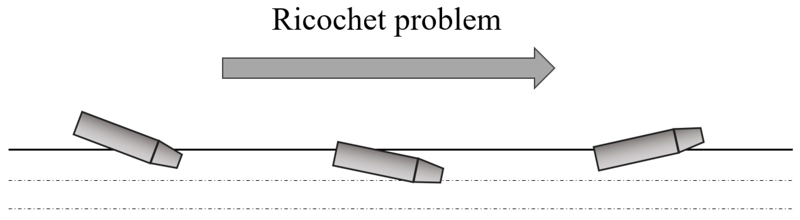
  • High-speed projectiles feature conical compact rigid-body designs (approximately 10 mm in diameter [9]) and enter water at ultra-high speeds ranging from hundreds to thousands of meters per second with minimal entry angles [9]. The coupling effects of extreme speed and small water entry angles often trigger dynamic issues such as structural bending, ricochet, and ballistic instability [10].
Table 1 summarizes the structural characteristics, water entry states, and main research issues of air-dropped torpedoes, supercavitating vehicles, and high-speed projectiles.
In summary, as demonstrated above and in Table 1, each of the three types of vehicles—air-dropped torpedoes, supercavitating vehicles, and high-speed projectiles—exhibits unique structural characteristics, water entry states, load impact challenges, and ballistic stability issues. These distinctions highlight the diverse engineering considerations and research priorities required for optimizing their performance during cross-media water entry. In the following sections, based on the research results of numerous domestic and international scholars on load reduction strategies and ballistic stability of vehicles during cross-media water entry, as well as the development history of high-speed water entry theories, experimental methods, and simulation techniques, the research progress in cross-media water entry is systematically reviewed. Recent advancements in artificial intelligence (AI) for solving cross-media problems are introduced, and future development trends in this field are discussed.

2. Water Entry Load and Load Reduction Strategies

The high-speed cross-media water entry process exhibits highly instantaneous and nonlinear characteristics. The water entry process can be divided into four distinct stages based on different phenomena: the surface impact stage, the liquid flow stage, the cavity formation stage, and the cavity closure stage [11].
  • Surface impact stage: During this stage, the head of the vehicle experiences a significant water entry impact load. Factors such as the head shape of the vehicle, water entry speed, and water entry angle have a substantial influence on the peak load [12,13,14]. The characteristics of the impact load in this stage include a high peak value and short duration [15]. The intense and instantaneous impact load can damage stress concentration points in the vehicle’s structure, potentially affecting the normal operation of electronic equipment in the vehicle’s head. According to Von Karman’s flat plate water entry impact model [16], the dynamic load peak aimpcat caused by the impact load is:
    a i m p a c t = F i m p a c t m = ρ c v A m
    where Fimpcat is the axial impact load; ρ is the density of the fluid; v is the relative velocity between the vehicle and the free surface of the water; c is the speed of sound in water; A is the wet area of the bow inlet surface; m is the mass of the vehicle.
2.
Liquid flow stage: The water is compressed and rapidly diffuses outward, causing the fluid pressure around the vehicle to drop sharply, which leads to cavitation [17]. During this stage, the vehicle is subjected to continuous hydrodynamic loads. The peak load is significantly smaller than in the surface impact stage, but the duration is longer, and the head wet area is also larger. As a result, the loads experienced during this stage can have a notable impact on the vehicle’s structure and its subsequent ballistic stability. The overload ahydrodynamic caused by the continuous hydrodynamic load can be expressed as:
a h y d r o d y n a m i c = F h y d r o d y n a m i c m = 1 2 ρ v 2 A C d m
where Fhydrodynamic is the axial hydrodynamic load; ρ is the density of the fluid; v is the relative velocity between the vehicle and the free surface of the water; A is the wet area of the bow inlet surface; m is the mass of the vehicle; Cd is the drag coefficient.
3.
Cavity formation stage: As the depth of the vehicle entering the water increases, cavitation flow gradually forms. During this stage, an open cavity is created if the speed of the vehicle is fast enough, meaning the interior of the cavity is connected to the outside atmosphere, and air is continuously entrained into the cavity. At this stage, a slamming effect may occur between the vehicle and the cavity wall, generating normal impact loads and pitching moments [18]. This can easily lead to transient changes in the pitch angular velocity of the vehicle.
4.
Cavity closure stage: As the vehicle continues to move forward, the volume of the cavity increases, and the vehicle becomes fully enveloped by the cavity. The cavity closure stage begins when the tail of the cavity starts to close under fluid pressure and surface tension. Due to various initial disturbance factors, the vehicle will repeatedly hit the upper and lower walls of the cavity after the initial slapping action. This results in periodic changes in the vehicle’s angular velocity, known as the tail-slapping phenomenon [19].
From the above analysis, it is evident that the normal load primarily arises from the wetting of the vehicle’s head and sidewalls, as well as the tail-slapping phenomenon, which predominantly occurs during the cavity formation and cavity closure stages. Yuan et al. [19] investigated the impact load characteristics of vehicles during high-speed water entry under typical working conditions and analyzed the variation characteristics of normal overload and axial overload. The results demonstrated that the normal overload can reach twice or even higher than the axial overload in cases involving the wetting of the vehicle’s head and sidewalls, as well as tail-slapping actions. This indicates that the normal load may pose a significant threat to the structural integrity of slender vehicles.
Figure 1 below illustrates the typical water entry states of air-dropped torpedoes, supercavitating vehicles, and high-speed projectiles during water entry: When entering the water at a large angle for air-dropped torpedoes, the head structure and internal electronic devices are susceptible to damage from impact loads. During the flat-turning process after water entry for supercavitating vehicles, the impact load on the head and the tail-slapping load can easily cause fractures in the large-size thin-shell structure. When entering the water at a small angle for high-speed projectile, a larger cavity is formed, and the impact loads on the head and tail can easily cause bending of the vehicle structure. Therefore, implementing certain load reduction strategies is essential. Reasonable load reduction strategies not only ensure the safety of the vehicle’s structure and its internal electronic devices but also maintain the stability of the vehicle’s motion and ballistics, ultimately achieving its intended strategic goals. The following sections discuss existing load reduction strategies from three aspects: shape-based load reduction, structural load resistance, and active load reduction.

2.1. Shape-Based Load Reduction

Shape-based load reduction primarily focuses on optimizing the two parameters in Equations (1) and (2), namely the wet area A of the onstream surface and the drag coefficient Cd. The existing research is mostly conducted through the design of the vehicle’s head geometry (nose cone) or cavitation device. Some scholars have also explored bionic designs inspired by biological structures to achieve the goal of reducing water entry loads and drag forces.
Bodily et al. [20] conducted an experimental study on the influence of high-speed projectile head shapes on axial hydrodynamic loads, designing high-speed projectiles with three different head shapes: conical, ogive, and flat. The results showed that, under the same conditions, the flat-head vehicle experienced the largest hydrodynamic load, while the conical vehicle experienced the smallest load. This is because the drag coefficient Cd of the flat-head vehicle is the largest, whereas that of the conical vehicle is the smallest. The schematic diagram of the three head-shaped high-speed projectiles entering the water is shown in Figure 2. Shafaghat et al. [21] also optimized the shape of an axisymmetric cavitator to achieve load reduction, and the results indicated that the optimal cavitator shape resembles a cone, which has the smallest drag coefficient and significantly reduces water entry loads. Lu et al. [22] conducted a simulation analysis on the influence of cavitator diameter on water entry loads and pointed out that increasing the cavitator diameter could reduce normal overload but would also introduce a large axial overload. This is because increasing the cavitator diameter can form a larger water entry cavity, reducing the wet area of the vehicle’s sidewall and thus decreasing normal overload. However, it also increases the wet area A of the onstream surface, leading to an increase in axial overload.
With the rapid development of bionic technology, more researchers have focused on reducing the water entry load of vehicles through bionic design. Many water birds in nature (such as gannets, kingfishers, etc.) [23,24] exhibit morphological and movement principles that can serve as references for reducing water entry loads in vehicles. Inspired by the head shape of the kingfisher, Wu [25] designed a bionic head structure and conducted comparative tests between this bionic structure and an oval vehicle during high-speed water entry. The results showed that, compared to the oval vehicle the bionic structure effectively suppressed the peak overload during the initial stage of water entry impact. This is because the wet area A of the onstream surface of the bionic structure is smaller at that stage, reducing the peak aimpcat of the impact overload.
In addition, smart materials and structures possess capabilities such as self-sensing, self-diagnosis, self-repair, and self-actuation. These materials can respond to changes in the external environment and adapt their shapes to maximize performance. Recently, some scholars have conducted a series of studies on the application of smart materials and structures in variable-configuration aircraft. For example, Chen et al. [26] designed a shape memory polymer composite (SMPC) tube with a multilayered filament winding structure based on shape memory polymer (SMP). By adjusting the ambient temperature, they modulated the effective engineering modulus of the SMPC to meet the deformation requirements of the skin in a variable chord-length wing structure. Similarly, Gong et al. [27] proposed and designed a mechanical metamaterial unit combining anti-chiral four-ligament and concave honeycomb structures. This design exhibits a large negative Poisson’s ratio, enabling it to “expand” longitudinally during transverse stretching, making it suitable as a core material for wings, which can effectively increase wing area and lift. The application of smart materials and structures to cross-media vehicles could enable programmable deformation of wings with variable chord lengths, variable sweep angles, and foldable configurations. This would ensure optimal hydrodynamic layouts during water entry, effectively mitigating the impact of water entry loads on the vehicle. These possibilities present promising avenues for future research.

2.2. Structural Load Resistance

The material selection and structural design of the vehicle significantly influence its resistance to high-speed water entry loads. The use of high-strength materials can effectively withstand the impact loads during water entry and reduce the risk of structural damage. Simultaneously, a well-designed structure, such as wedge–ring connections, vibration-damping shells, and other similar configurations, can effectively absorb or disperse impact loads while also reducing vibrations. This helps minimize the impact on internal electronic devices and ensures the normal operation of guidance and control equipment.
Compared to traditional metals, the application of high-strength materials such as alloys and composites in torpedo shell construction has significantly enhanced the load resistance of the structure. The U.S. Navy has adopted a new aluminum–lithium alloy for heavy torpedoes [28], which offers high strength, excellent corrosion resistance, and remarkable load resistance performance. Additionally, materials like magnesium alloy and titanium alloy, known for their high strength, can effectively withstand water entry loads, making them excellent choices for vehicle materials. These materials demonstrate promising application prospects in torpedo design [29,30].
Wang Sheng [31] and He Zheng [32] et al. conducted a simulation study on the influence of wedge–ring connection structure on the force of air-dropped torpedo during water entry. The results revealed that the axial impact load borne by the tail section is smaller than that borne by the head section. This is because the shell response caused by the impact load propagates backward in the form of stress waves, while the interaction at the wedge–ring connection leads to energy dissipation, thereby providing buffering and damping effects against the shock. Han [33] designed a double-layer shell structure with spring and viscoelastic damping material and conducted simulation analysis in order to reduce the impact of the tail-slapping normal overload on the structure and internal components of the supercavitating vehicle. The simplified computational model of the double-layer shell structure is shown below as shown in Figure 3. Numerical calculations showed that within 1 s, the tail-slapping frequency of the double-layer vibration-damped shell structure is approximated to be 10.53% less than that of the single-layer shell, the last tail-slapping period is approximated to be extended to 0.33 s, so the negative effects of the tail-slapping normal overload are significantly reduced. This is attributed to the energy storage capability of the springs and the energy dissipation properties of the damping materials, which reduce the kinetic energy of the tail-slapping impact, disperse the inward transfer of vibrational energy, and provide effective vibration and load reduction.

2.3. Active Load Reduction

The average water entry impact load on the head of a vehicle during a given period of time Δt can be approximated using the Impulse Theorem equation:
F · Δ t = p 1 p 0 = m 1 v 1 m 0 v 0
where F is the average water entry impact load; Δt is the water impact action time of the vehicle; p1 is the momentum of the vehicle in the final state; p0 is momentum of vehicle in the initial state; m1 is the mass of the vehicle in the final state; v1 is the speed of the vehicle in the final state; m0 is the mass of the vehicle in the initial state; v0 is the speed of the vehicle in the initial state.
During the high-speed water entry of the vehicle, researchers often focus on extending the time Δt of the impact to achieve load reduction. This approach aims to alleviate the damage caused by impact loads on the vehicle’s structure and internal electronic devices during water entry. Commonly used load reduction measures include parachute, jet load reduction, buffer headcap, spring, air chamber, and its composite structures. Table 2 below summarizes the load reduction mechanisms of these methods and the types of applicable vehicles.
Equipping a parachute is a common way to reduce the speed of air-dropped torpedoes into the water, as shown in Figure 4. When the parachute is deployed, the contact area between the parachute surface and the air increases significantly, and the motion resistance of the air-dropped torpedo increases, which significantly reduces the vehicle’s velocity before water entry [34], thereby relatively extending the water impact action time Δt of the vehicle and reducing the average water entry impact load F on the vehicle. Li [35] systematically introduced the type selection, parachute deployment methods, and determination of main parameters for torpedo parachutes, providing technical support for their design and selection. Jiang et al. [36] conducted numerical simulation analysis on the processes of parachute inflation, deployment, and descent, investigating the effects of different parachute designs on aerodynamic deceleration characteristics. The results revealed that parachutes with different gap-aperture structures exhibited significantly different aerodynamic performance: the drag coefficient of the middle gap model was higher, while the lateral force stability of the top gap model was better. For the next generation of parachutes with more complex combinations of seams and gaps, their aerodynamic characteristics and influencing mechanisms require further study.
The air jet load reduction method generates gas at the head or side of the vehicle and injects the gas jet into the water to form an air cushion [37]. The air cushion effect causes the pressure peak to occur not at the bow of the vehicle but at the gas–water interface below the bow [38]. This prolongs the water impact time Δt and further reduces the impact load during water entry. The process is illustrated in Figure 5. Researchers have conducted many studies on the effects of jet flow, jet structure, jet pressure, and altitude on the jet load reduction effect: Liu et al. [39] performed numerical simulation analysis to investigate the impact of different jet flows on water entry impact load. The study highlighted that the head jet can effectively reduce water entry impact load, and the load reduction effect becomes more significant as the jet flow increases. This is because, when the head jet volume is too small, cavity collapse occurs, resulting in a relatively weaker load reduction effect [40]. Wei et al. [41] conducted a numerical simulation analysis to investigate the influence of nozzle structure shape on load reduction, designing three types of nozzle structures, namely equal-diameter nozzle, shrinking nozzle, and expanding nozzle. The results showed that the load reduction effect of the equal-diameter nozzle structure is better than that of the shrinking and expanding nozzles. This is because the attachment cavity formed by the shrinking and expanding nozzles is smaller than that of the equal-diameter nozzle, resulting in a less effective load reduction performance. Peng et al. [42] analyzed the effects of jet pressure and jet height on the load reduction effect, and the results showed that the influence of jet pressure and jet height on the peak impact load was little. Therefore, appropriate jet parameters should be selected based on the actual water entry conditions to achieve both load reduction and cost efficiency. Nowadays, when the water entry speed is relatively low, the effectiveness of reasonable jet load reduction can reach up to 90% [41]. However, when the speed increases to the order of hundreds of meters per second, the load reduction effectiveness of jets decreases significantly [42]. Therefore, for high subsonic and higher speeds, further exploration of other load reduction methods is necessary.
The buffer headcap can replace the head of the vehicle and interact with the water surface. In the surface impact stage, compared to rigid vehicle impact, the elastic buffer material contained within the structure will not only prolong the water impact time Δt, but also absorb strong impact energy. The material undergoes gradual compression, failure, and destruction until it detaches from the vehicle, ensuring the safety of the vehicle’s head structure and internal components during water entry. This mechanism is commonly used as a water load reduction structure for large blunt bodies such as air-dropped torpedoes and Autonomous Underwater Vehicles (AUVs) [43]. Through long-term improvement and optimization, the buffer headcap has evolved from its original monolithic structure [44] to a composite structure consisting of a rectifier head cover, buffer material, fixed parts, and connecting components [45], as shown in Figure 6. Yan [46] earlier explored the characteristics of rigid polyurethane headcaps through theoretical methods, highlighting that the headcap structure can significantly reduce the peak impact pressure during water impact and prolong the impact action time to flatten the water entry load. Subsequently, Wang et al. [47] modified the constitutive equation of polyurethane foam accordingly. The numerical calculation results show that the modified constitutive equation is simpler and more universal compared to the traditional empirical methods and is more suitable for the actual situation. Wei et al. [48] investigated the influence of layered buffer materials on load reduction performance. By increasing the density and strength of buffer materials inside the headcap in sequence, the results showed that compared with single-layer buffer materials, the layered buffer material exhibited a more significant energy absorption effect and demonstrated a “secondary energy absorption” effect. This is because the harder layers of the layered buffer material are not easily completely destroyed during the surface impact stage but detach from the vehicle after entering the water for a certain period of time. Shi et al. [49] further investigated the influence of density arrangement in layered buffer materials on load reduction characteristics and designed headcap structures with a positive and negative density gradient arrangement, as well as varying density differences between layers. The results indicate that the buffering capacity of the negative density gradient arrangement of the buffer headcap is better than that of the positive density gradient arrangement. This is because the dynamic stress tends to shrink when the stress wave propagates through the negative density gradients. Additionally, when the density difference between layers is larger, the load reduction effect of the buffer headcap is better, which is due to the larger transfer loss of impact energy. Furthermore, many scholars have conducted detailed studies on the failure behavior of the buffer headcap structure [50,51,52], concluding with the deformation and failure forms of the buffer headcap structure.
The spring buffer and air chamber buffer structure can not only prolong the water entry impact time Δt but also absorb the energy generated by the impact load, thereby achieving load reduction. Different from the crushing failure of the buffer headcap structure after energy absorption, the spring structure converts the impact energy into the elastic potential energy of the spring [53], while the air chamber structure uses the compressibility of gas to absorb the impact energy during water entry [54]. Both mechanisms effectively reduce the peak impact load and gradually release energy after entering the water. The schematic diagrams of the two structures are shown in Figure 7 below. When the load reduction effect of a single buffer structure is limited, researchers have proposed combined load reduction schemes, such as the integration of spring and cavitator, buffer material and cavitator, and buffer material and air chamber. These combined load reduction methods significantly mitigate the impact response of the vehicle during water entry and effectively reduce the adverse effects of impact load on the vehicle. Sui et al. [55] designed a vehicle with a spring structure connected between the main body and a disk cavitator, conducted an experimental study on the load reduction effect of the combined buffer device, and discussed the influence of the spring stiffness and disk mass on the load reduction characteristics. The study found that the combined buffer device achieves an optimal load reduction effect only when the spring stiffness is within a certain range. Excessive spring stiffness will increase the peak value of the water entry impact load. Additionally, increasing the mass of the disk cavitator contributes to load reduction, but excessive mass causes fluctuations in the peak impact load, which is because the increasing mass reduces the natural frequency of the system.
In addition, some scholars have proposed to fill the buffer material between the vehicle and the cavitator, with the cavitator and buffer material connected by telescopic rods, thereby forming a multi-stage load reduction structure [56,57]. Compared with direct water entry without a load reduction structure, the multi-stage load reduction structure can smoothly transform the impact load into multiple smaller acceleration peaks, significantly mitigating the impact on the vehicle. Wang [58] designed a combined structure of aluminum foam buffer material and air chamber structure, studying the load reduction mechanism of the combined buffer device. The results showed that aluminum foam provides a load reduction effect during the initial stage of water impact, exhibiting a layer-by-layer compression trend that effectively absorbs impact energy and reduces the amplitude of the load transmitted to the rear of the vehicle. In contrast, the air chamber structure exhibits a certain delay in the effective time of load reduction, and its performance is influenced if the initial internal pressure of the air chamber is either too low or too high.

3. Water Entry Ballistic Stability

The vehicle experiences complex multiphase flow and sudden medium changes during the process of high-speed cross-media entry, exhibiting significant non-steadiness characteristics. At the same time, the strong impact load significantly affects the ballistic stability and motion controllability [59]. Especially in the case of oblique entry of air-dropped torpedoes and high-speed projectiles, the unbalanced forces generate large step changes in momentum, causing substantial variations in the vehicle’s attitude angle. This can lead to a sudden whip phenomenon and even inducing ricochet behavior [60], which adversely affects the vehicle’s motion attitude and its tactical performance. For supercavitating vehicles, their unique cavitator design and fixed cavitation separation position characteristics can effectively avoid the sudden whip phenomenon caused by head cavitation [61]. After water entry, the supercavitating vehicle needs to complete the flat-turning operation quickly, which is crucial to maintain the stability of the cavity form, and the stable cavity form can ensure that the vehicle maintains the high-speed movement in the water, thereby enhancing its range and maneuverability. Consequently, the flat-turning process of the supercavitating vehicle and its ballistic characteristics after water entry are also key research focuses for many scholars.
In order to quickly predict whether the vehicle will ricochet after entering the water at high speed, the author summarized and put forward the judgment criteria of the slip inside the yaw plane through experimental analysis.
θ w a t e r = θ 0 + θ d e f l e c t i o n = θ 0 + ω 0 t + 1 2 M I z t 2 = 0 , r i c o c h e t < 0 , w a t e r e n t r y
where θwater is the attitude angle of the vehicle in the water; θ0 is the angle of incidence; θdeflection is the deflection angle of the vehicle under the action of pitching moment during water entry; ω0 is the initial pitch angle velocity at the moment of water entry; t is the water entry time, usually defined as the time required for the entire vehicle to fully enter the water, that is, t = L/v, and L is the reference length; M is the normal moment of the head of the vehicle, M = Fy_caXc, where Xc is the position of the center of mass, Fy_ca = 0.5ρv2ACdsinθca, and θca is the initial disturbance angle into the water; Iz is the rotational inertia of the vehicle about the yaw axis.
For air-dropped torpedoes, supercavitating vehicles, and high-speed projectiles, the first two are typically large-size thin-shell structures, while high-speed projectiles are generally small-size rigid structures, so the rotational inertia of high-speed projectiles is usually much smaller than that of air-dropped torpedoes and supercavitating vehicles. Combined with their extremely high water entry speeds, the water entry impact load and pitching moment of high-speed projectiles are significantly greater than those of the first two. According to the above criteria, the deflection angle θdeflection of high-speed projectiles is much larger than the first two, so it is more prone to induce a sudden whip phenomenon or even ricochet behavior after high-speed water entry. The following is a summary of the current research status from three aspects: the whip problem of air-dropped torpedoes, the flat-turning problem of supercavitating vehicles, and the ricochet problem of high-speed projectiles.

3.1. Whip Problem of Air-Dropped Torpedoes

During the process of high-speed oblique water entry, after the bow hits the water, the pressure difference between the upper and lower surfaces causes the torpedo body to pitch upward, changing its initial trajectory, which can lead to the torpedo suddenly emerging from the water surface. After entering the water, a long and narrow cavity attached to the lower part of the torpedo body forms a low-pressure area, creating an unbalanced moment that induces a downward pitching motion, which will greatly change the attitude of the torpedo [62], as shown in Figure 8. The above two conditions are the primary reasons for the sudden whip of air-dropped torpedoes. Maintaining the stability of air-dropped torpedoes’ water entry trajectory remains one of the key research challenges in this field.
In the early stage, Yan [63] discussed the conditions for maintaining the attitude motion stability of air-dropped torpedoes during water entry and proposed that the ballistic stability of water entry could be improved by designing the tail stabilizer. This is because the tail stabilizer ensures that the tail of the torpedo remains in a wetted state, allowing the tail force system to maintain a smooth and sustained state, thereby avoiding the whip phenomenon. Wang et al. [64] studied the impact of torpedo mass on ballistic stability and pointed out that under the same conditions, a smaller mass increases the likelihood of sudden whip behavior. This is due to the smaller rotational moment of the torpedo; as seen in Equation (4), a smaller mass results in a smaller deflection angle, making sudden whip behavior more likely. Zhang et al. [65] investigated the effect of the water entry angle of attack on the low-pressure region of the cavitation, and noted that a negative angle of attack is larger and lasts longer than that under a positive angle of attack, which is detrimental to the stability of the torpedo’s water entry ballistics. In addition, the stability of the torpedo’s water entry ballistics is also influenced by initial parameters such as head shape, water entry velocity, water entry angle, and so on [66]. Therefore, a comprehensive analysis considering various factors is essential when studying ballistic stability.

3.2. Flat-Turning Problem of Supercavitating Vehicles

The rapid flat-turning of supercavitating vehicles after water entry is essential for maintaining the shape of the cavity, enabling the vehicle to advance at high speed within the stable cavity [67]. This capability provides high maneuverability, strong concealment, and rapid striking potential. Therefore, understanding the influencing factors and characteristics of the flat-turning ballistic after water entry is crucial for ensuring the stability of the flat-turning process.
In the early stage, Kirschner et al. [68] proposed that a preset rudder angle could provide stable lift and a pitch-up moment for the supercavitating vehicles to turn flat and realize maneuvering turns based on the cavity morphology and tail-slapping characteristics obtained by the free flight test of the supercavitating vehicle. Subsequently, Yuan [69], Liu [70], and other scholars conducted in-depth research on the influence of preset rudder angle on the ballistic stability of supercavitating vehicles. They pointed out that the larger the preset rudder angle, the stronger the flat-turning and deflecting ability of supercavitating vehicles during water entry.
In addition to the preset rudder angle of the cavitator, the tail configuration is also a critical factor influencing the flat-turning ballistics and stability of supercavitating vehicles during high-speed water entry. The extended tail skirt provides a recovery moment during the flat-turning ballistics, limiting the continuous increase in the angle of attack and ensuring the stability of the flat-turning process. Therefore, the reasonable design of the preset rudder angle and tail configuration of supercavitating vehicles, so as to maintain the ballistic stability while possessing the deflection capability [71], is crucial to ensure the strike accuracy and combat effectiveness of the supercavitating vehicles. In addition, Huang et al. [72] analyzed the influence of material density on the stability of the tail-slapping motion of the supercavitating vehicles and pointed out that the larger material density results in a longer tail-slapping motion period and reduces the impact of tail-slapping loads on ballistic stability. This is because with the increase in material density, the oscillation frequency and amplitude of pitch velocity decrease, which enhances ballistic stability.

3.3. Ricochet Problem of High-Speed Projectiles

In the early stage, Miloh [73], Hutchings [74], and other scholars carried out theoretical studies on the ballistic stability of spheres and cylinders entering water and calculated the critical water entry angle for ricochet behavior, which laid the foundation for the subsequent research on the ballistic stability of high-speed projectiles during water entry. Subsequently, Park et al. [75] developed a numerical method to study the ricochet behavior of projectiles into water. Based on the theory of inviscid potential flow, the method calculated the impact load of water entry and simulated the ricochet behavior under different conditions. The process of high-speed projectiles entering water is shown in Figure 9. It can be seen that, due to the effect of a large pitching moment during high-speed water entry, the attitude deflection of the main body becomes excessive, resulting in ricocheting and failing to enter the water successfully.
In recent years, the influence of different initial conditions on the ballistic stability of high-speed projectiles entering water has been widely studied. Wang [76], Li [77], Qi [3], and other scholars have studied the impact of initial parameters such as the angle of attack and rotational motion on ballistic stability. They pointed out that reducing the angle of attack and minimizing rotational motion contribute to maintaining the stability of high-speed water entry ballistics. Qi et al. [78] proposed a stepped cylindrical high-speed projectile design based on the principle of the “cavitation effect of cavitation devices” and analyzed its water entry stability. The results show that compared with the conical cylindrical shape vehicle, the stepped cylindrical design improves the ballistic stability at the initial stage of water entry, because the stepped cylindrical shape accelerates the development of the water entry cavity, generating a restoring moment that inhibits the tendency of the angle of attack to increase. In addition, some scholars have also studied the effects of high-speed projectile head shape, center of mass position, and other factors [79,80] on the stability of water entry ballistics. They pointed out that the stability of water entry ballistics is highly dependent on the wet surface area of the head. The design of flat-head high-speed projectile is beneficial to improve the stability of water entry, but due to its high drag coefficient, the velocity decreases too rapidly. It is also found that when the center of mass is far from the top of the vehicle, the sudden whip phenomenon becomes more severe, which is because the normal load acting on the bow generates a larger pitching moment.

4. Research Methods for Cross-Media Water Entry

The cross-media water entry process is typically completed in an extremely short time, involving complex interactions among solid, air, and liquid phases. It is accompanied by non-stationary phenomena such as cavitation effects, cavity generation and collapse, and free surface fluctuations, which are highly nonlinear and strongly transient in nature. The continuous development and refinement of theoretical, experimental, and simulation research methods have advanced the systematic study of cross-media water entry, laying the foundation for the engineering application of cross-media water entry weapons. In recent years, with the development of artificial intelligence technology, the use of AI to solve cross-media problems has also yielded remarkable results.

4.1. Theoretical Research

The theoretical research methods of cross-media water entry are usually based on the potential flow theory [81] to solve the analytical solution of the water entry problem. These studies generally focus on theoretical research on the water entry impact load and the evolution of the water entry cavity. Table 3 below summarizes the main researchers involved in theoretical studies on impact loads and cavity evolution during water entry at different stages of research, along with their key achievements and contributions.
The theoretical study of cross-media water entry impact load characteristics began with Von Karman [16], who introduced the concept of added mass and applied the momentum conservation law to calculate the impact pressure during seaplane landings. Later, Wagner [82] considered the influence of changes in boundary conditions, such as the rise of free liquid surface during water entry. He equated the wedge to a flat plate, and introduced the correction factor for the deadrise angle of the wedge, thereby proposing an approximate flat plate theory for the model with a small deadrise angle. The theoretical contributions of these two researchers laid the foundation for modern water entry theory, and many subsequent studies have been developed based on their work. Based on the Wagner model, Logvinovich [83] considered the nonlinear term in the Bernoulli equation and introduced an added velocity term at the solid–liquid contact point to establish the Original Logvinovich Method (OLM). Compared to the traditional method, the OLM reflects complex velocity changes at the solid–liquid contact point and more accurately reflects nonlinear phenomena such as shockwave propagation and rapid liquid separation during solid–liquid contact. After that, Korobkin et al. [84] developed the Modified Logvinovich Method (MLM) based on the OLM, which further optimized the treatment of nonlinear terms and added velocity terms. The MLM can simulate more complex object geometries, motion patterns, and water entry impact behaviors under flowing conditions. In addition, Dobrovol’skaya [85] applied the self-similarity theory to study the two-dimensional flow problem of incompressible fluid under free surface conditions. Based on the Wagner model, this theory introduced self-similar variables and transformed the free surface flow problem into a nonlinear singular integral equation problem of real functions for solving. It provides effective theoretical and numerical tools for dealing with complex free surface flow problems. Through the simplified analysis of these theories, the variation laws of the impact load can be intuitively understood using calculation formulas, making it convenient for direct engineering applications. However, due to the complexity and diversity of actual problems, many challenges remain to be solved.
The compressibility of the fluid was not considered in the early theoretical studies. Later, it was discovered that when the object’s head has significant bluntness or the velocity is very high, the compressibility of the fluid will play a crucial role in the calculation of the water entry impact load. When the compressibility of the fluid is considered, the calculation of the drag coefficient of water entry and the size of the cavity will increase [86,87]. Earlier studies of fluid compressibility were conducted by Egorov [88] and Borg [89], who investigated the process of a blunt-headed body impacting the compressible fluid and pointed out that the time scale of the effect of water compressibility satisfies tc = 1/2c, where c is the speed of sound in water. Later, Korobkin [90] considered the compressibility of the fluid and refined the cross-media water entry process into five stages: supersonic stage, transonic stage, subsonic stage, inertia stage, and the stage of developed liquid flow.
In the theoretical study of the evolution of water entry cavity, Rayleigh [91] in the early stage derived the equation of motion for cavitation bubbles in an incompressible ideal fluid, known as Rayleigh’s equation. Later, Plesset [92] expanded this model by incorporating viscosity and surface tension terms, resulting in the renowned Rayleigh–Plesset equation. This equation describes the kinetic behavior of cavitation bubbles under the influence of pressure changes, viscosity, and surface tension. It plays a crucial role in the study of bubble dynamics, bubble growth, and the acoustic behavior of cavitation bubbles. Later, Garabedian [93] solved the free surface flow problem under axisymmetric conditions through the perturbation method of parameter expansion, and derived and verified the asymptotic expressions of the width, length, and related physical parameters of the cavitation, named as the Garabedian formula. Logvinovich [83] proposed the independence principle of the cavity section expansion. By decomposing the complex cavity morphology into the independent expansion problem of each section, the principle realized the theoretical calculation of the evolution of unsteady cavity in different sections, laying the foundation for subsequent theoretical research. Later, Truscott [94] analyzed the effects of velocity, geometry and angle of attack on cavity formation by improving Logvinovich’s theoretical model and conducting full-scale tests, thereby optimizing the shape design of the vehicle. Vasin [95] discussed the application of the Logvinovich theoretical model in the calculation of unsteady cavity and external pressure changes, and analyzed the cavity shape affected by gravity.
In addition, Lundstrom et al. [96] summarized the evolution law of cavity shapes for cross-media water entry vehicles and derived an empirical formula of cavity radius based on the law of energy conservation. Building on Lundstrom’s work, Lee et al. [97] proposed a theoretical model for predicting the evolution of cavity shapes. This model is applicable to objects of any shape and velocity, and can accurately describe important variables, such as closure time and closure position. However, at present, due to the complexity of flows, it is difficult to summarize a universally applicable theoretical model that can accurately describe the entire physical phenomenon. Current research typically simplifies the problem by ignoring secondary factors and then establishes corresponding mathematical models.

4.2. Experimental Research

With the increasing demands of engineering applications, more scholars pay attention to the experimental research related to cross-media water entry, and the research direction is increasingly centered on the water entry characteristics of various types of vehicles in practical applications. In the field of cross-media water entry testing, the experimental techniques for high-speed projectiles and other small-size vehicles entering water have become increasingly refined. However, for large-size vehicle structures such as air-dropped torpedoes and supercavitating vehicles, the test conditions often cannot support high-speed water entry tests of full-size models. As a result, most experimental studies have adopted the scaled-down method for similarity analysis [98].
To accurately represent the main phenomena and properties of a full-size model on a scaled-down model and to use the scaled-down model to predict the flow evolution process of the full-size model during water entry, it is essential to maintain the mechanical similarity relationship between the flow of the scaled model and the flow of the full-size model. This means that the corresponding physical quantities of the two models at corresponding points must maintain a specific proportional relationship. To conduct hydrodynamic scaled-down tests, the commonly used dimensionless similarity parameters include the Froude number (Fr), cavitation number (σ), Reynolds number (Re), Weber number (We), capillary number (Ca), and Mach number (Ma). Assuming an entry velocity of 100 m/s for the high-speed water entry scaled-down test, a characteristic length of 20 cm for the water entry object, and a room temperature of 20 °C, the calculated values of these dimensionless similarity parameters are presented in Table 4 below.
Analysis of the data in the table reveals that, under the test conditions, the Reynolds and Weber numbers exhibit extremely high values, while the capillary number is 1.376, indicating that the effects of viscous forces and surface tension are comparable and can both be neglected. The Mach number is small, suggesting that the flow can be approximated as incompressible. In contrast, the Froude number indicates that gravity has a more significant influence on the test, necessitating that the effect of gravity be accurately scaled. The cavitation number, with a value much less than 1, confirms that cavitation effects are significant. Therefore, the Froude number similarity and cavitation number similarity are the primary similarity criteria used in water entry scaled-down tests [99,100]. The Froude number is a dimensionless parameter used to characterize the relative magnitude of fluid inertial forces to gravity, defined as the ratio of the fluid’s flow velocity to the square root of the product of gravitational acceleration and the characteristic length:
F r = V g L
where V is the flow velocity; g is the gravitational acceleration; L is the characteristic length, such as the length of an object or the depth of a fluid. In flows with similar dynamics, the Froude number remains constant, indicating that the fluid motion is similar regardless of the physical dimensions of the problem.
Cavitation number σ is a dimensionless parameter in fluid mechanics that describes the cavitation state, measuring whether cavitation occurs in liquid flow and the degree of cavitation development. Its expression is:
σ = p p v 1 2 ρ V 2
where p is the incoming flow pressure of the liquid; pv is the saturated vapor pressure of the liquid at the ambient temperature; ρ is the density of the liquid; V is the flow velocity of the liquid.
The cavitation number is essentially a special form of the Euler number, which reflects the proportional relationship between the flow parameter that inhibits cavitation (i.e., the pressure difference p − pv) and the flow parameter that promotes cavitation (i.e., the velocity V). At room temperature, the saturated vapor pressure of water is approximately 2338.8 Pa. The value of the cavitation number depends on the pressure difference, fluid velocity, and density. When the fluid velocity is larger and the pressure difference is smaller, the cavitation number decreases. If the cavitation number falls below a critical value, cavitation occurs in the liquid or gas. Additionally, the cavitation number can also characterize the similarity of cavitation between two fluid systems under specific conditions. That is, when similar parameters such as Reynolds number and Froude number are equal, if the cavitation numbers of the two fluid systems are equal, the cavitation phenomenon can be considered the same.
In the 1950s, the United States conducted the MK25 aerial torpedo water entry test [101], which used a scaled-down model at a 1:11 ratio (model diameter 50.5 mm, length 173.4 mm). The similarity criteria applied in the test design were Froude number similarity and Cavitation number similarity, achieved through dimensional and velocity scaling, as well as the use of a decompression tank. Subsequently, many scholars have conducted numerous water entry tests using scaled-down models based on this design approach. However, these tests face some unavoidable challenges:
Firstly, scale effects in the scaled-down tests. In small-scale models, the viscous effects of fluids are usually more prominent, while in full-size models, the inertial forces may be more significant. The similarity between the model and the prototype may only be maintained under specific conditions, resulting in different behaviors of critical physical phenomena such as turbulence, fluctuation, and vibration between the two models.
Secondly, limitations of Froude number similarity. Froude number similarity focuses on the relative importance of inertial forces and gravity in scaled-down experimental design but neglects other flow effects. When viscous effects are significant in fluid flow, Froude number similarity may conflict with other critical similarity conditions, such as Reynolds number similarity.
Thirdly, challenges in Cavitation number similarity. To ensure cavitation number similarity, water surface pumping is required to reduce liquid flow pressure. For large-scale test pools, pumping is highly challenging and costly. As a result, it is often impossible to maintain cavitation number similarity throughout the entire water entry process, but rather that some design can achieve cavitation number similarity at typical locations.
Thus, compared to the scaled-down model test, the full-size model test has obvious advantages in simulation authenticity and test accuracy. Qi et al. [102] conducted high-speed water entry test of a full-size AUV model using an air gun as a launching device. They explored the relationship between the water entry angle and the cavitation phenomenon at the head of the AUV and obtained test data on the impact load of the full size AUV entering water at high speed. Other studies on the full-size test have been rarely reported.

4.3. Numerical Simulation

Reviewing the research history of water entry impact problem, from early studies to the end of the last century, the water entry structure is regarded as a rigid body in most cases, and this assumption is generally reasonable for solving the water entry impact problem for small-size solid structures [103]. However, with the in-depth study of large-size thin-shell structures, such as air-dropped torpedoes and supercavitating vehicles, researchers found that their elastic effects cannot be ignored [104]. When structural elasticity is taken into account, the fluid–structure interaction (FSI) problem becomes a significant challenge in solving cross-media water entry problems. The fluid–structure interaction problem is mainly characterized by the interaction between fluid and solid structure, including the deformation or motion of the structure under the action of fluid loads and the influence of the structure deformation or motion on the flow field. Therefore, the solution of the FSI problem requires simultaneous consideration of the flow field, the structural field, and their coupling. With the continuous development of numerical simulation technology, two types of methods, the monolithic approach and the partitioned approach [93,94,95,96,97,98], have been widely used in the solution of the FSI problem.
Monolithic approach refers to a numerical method that simultaneously solves the coupled equations of the flow field and the structural field in the same time step [105], as shown in Figure 10 below. This method can not only consider the interaction between the fluid and the structure simultaneously, but also effectively avoids the accumulation of time errors that may occur in the partitioned approach, so the calculation accuracy is high. Ryzhakov et al. [106] proposed a Lagrangian method based on the monolithic approach to solve the governing equations of the flow field and the structural field. They analyzed and solved numerical examples, such as the deformation of an elastic plate under water pressure. The results showed that the monolithic approach can accurately compute the structural response with high computational efficiency and excellent numerical convergence, making it suitable for solving small-scale fluid–structure interaction problems. However, for the complex large-scale fluid–structure interaction problems, such as cross-media water entry of supercavitating vehicles, the monolithic approach involves extensive mathematical operations and complex numerical stability issues, leading to significant challenges in solving such problems. As a result, it has not yet been effectively applied to these scenarios.
Partitioned approach involves dividing the fluid–structure interaction problem into several separate solution steps, alternately calculating the governing equations for the fluid and structural fields. Specifically, within each time step, one field (fluid or structural) is solved first, and then the boundary conditions of the other field are updated based on the solution results. The solution of the other field is then continued using the updated boundary conditions until convergence requirements are met. The partitioned approach can be further classified into loosely coupled and tightly coupled algorithms, depending on the degree of coupling [107].
In the loosely coupled algorithm, the solution processes of the fluid and structural fields are separated within each time step, and they are coupled through iteration and information transfer, with staggered time advances to obtain the response of the coupled system, as shown in Figure 11 below. Xu et al. [108] established a computational fluid dynamics (CFD)/computational structural dynamics (CSD) bidirectional coupling analysis method based on the loosely coupled algorithm. They analyzed the tail-slapping cavity type, structural deformation, and tail-slapping load characteristics of elastic vehicles. The results showed that during the tail-slapping process of elastic vehicles, the structure of the vehicle and the cavitation exhibit significant fluid–structure interaction effects, and the tail-slapping load presents a distinct multi-peak phenomenon. For fluid–structure interaction problems involving small deformations, the interaction effect between the fluid and the structure is relatively weak, and the loosely coupled algorithm can provide an effective solution with high computational efficiency. However, for problems involving strong interactions, nonlinearities, or large deformations, the loosely coupled algorithm is prone to convergence issues or poor accuracy due to error accumulation caused by the time step delay effect.
Based on the loosely coupled algorithm, the tightly coupled algorithm introduces sub-iterative steps within each time step. In each sub-iterative step, the flow control equation and the structural dynamics equation are solved, and data are exchanged through the fluid–structure interaction interface [109], as shown in Figure 12 below. Compared to the loosely coupled algorithm, the tightly coupled algorithm better solves the time delay issue in solving the flow field and structural field. The multiple data exchanges during the sub-iteration process ensure reasonable convergence accuracy for the flow field, structural field, and fluid–structure interaction, resulting in higher computational accuracy. Shi et al. [110] investigated the fluid–structure interaction effects of an elastic AUV during cross-media water entry using the Arbitrary Lagrangian–Eulerian (ALE) method based on the tightly coupled algorithm. The results showed that the elastic deformation of the AUV primarily occurs in the head region, and the hydroelastic effect is obvious. The tightly coupled algorithm is suitable for solving the strong coupling problems between fluid and structure, which is more stable and accurate than the loosely coupled algorithm.

4.4. Artificial Intelligence in Cross-Media Problems

In recent years, the application of AI technologies in the field of fluid mechanics has made significant progress. Their powerful capabilities in feature learning and complex data extraction have reduced the reliance on high-performance computing equipment for numerical simulations, providing new solutions for addressing complex fluid problems. Traditional numerical methods are often computationally expensive and struggle to accurately capture interface dynamics and multi-scale effects. In contrast, AI can significantly accelerate the solution process while maintaining considerable prediction accuracy. By learning patterns from experimental or high-precision simulation data in a data-driven manner, AI constructs efficient surrogate models that offer innovative approaches to solving cross-media challenges.
Wei et al. [111] investigated the cross-media hydrodynamic properties of underwater vehicles using experiments and machine learning (ML). They designed a two-layer forward propagation neural network for training, and the results demonstrated that the cross-media resistance of underwater vehicles can be accurately predicted within a certain range using this combined approach. Lv et al. [112] utilized deep neural network (DNN) to predict the peak impact load during the oblique water entry of cylinders with different nose shapes. The results showed that the DNN model, validated and further optimized through experimental results, can efficiently and accurately predict the peaks of axial and normal accelerations. Additionally, Huang et al. [113] proposed a parallel neural network (PNN) model by integrating numerical simulation and ML to study the hydrodynamic behavior of a ship during the water-exit process. Their results indicated that the PNN model could reduce the solution process from approximately 70 h using traditional methods to a model training process of about 1 h. The trained PNN model could predict hydrodynamic parameters for each wave phase in just a few seconds, with a mean square error (MSE) of less than 0.01%, maintaining high accuracy. Zhang et al. [114] developed a model based on ML to rapidly predict the parameters related to the cross-media water exit under various wave conditions. The results showed that the constructed three-layer backpropagation neural network could effectively predict the motion parameters and load characteristics of the vehicle during the cross-media water-exit process.

5. Summary and Prospects

This paper primarily focuses on the cross-media water entry processes of three typical vehicles—air-dropped torpedoes, high-speed projectiles, and supercavitating vehicles—and systematically reviews the current research status and progress in their water entry impact loads, load reduction strategies, water entry ballistic stability, and research methods for cross-media water entry. The abundant research results provide valuable references for impact load prediction, motion control, and structural design during cross-media water entry, laying a solid foundation for further development in related theories, experiments, and numerical methods. Future research on cross-media water entry can focus on the following directions:
  • Water entry impact load and load reduction strategies: Current load reduction strategies primarily focus on the damage caused by axial impact loads to the head structure and internal components during the surface impact stage. However, when the vehicle enters the water at a small angle or with an angle of attack, or when the cavity asymmetrically closes around the vehicle structure, the negative effects of normal loads on the mid-section or aft section of the vehicle cannot be ignored. At present, research on normal load characteristics and load reduction strategies is insufficient and requires further development.
  • Water entry ballistic stability: Current research on ballistic stability primarily focuses on the whip phenomenon of air-dropped torpedoes, the flat-turning problem of supercavitating vehicles, and the ricochet phenomenon of high-speed projectiles. However, theoretical research on motion stability has rarely been reported, and the mechanism of complex phenomena such as whip remain unclear. Further research can also explore efficient methods for enhancing stability.
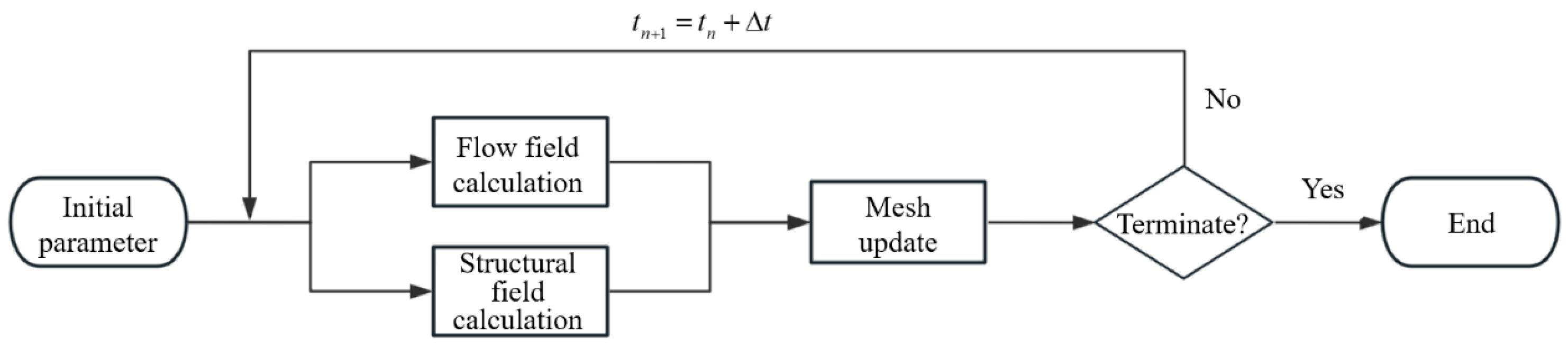
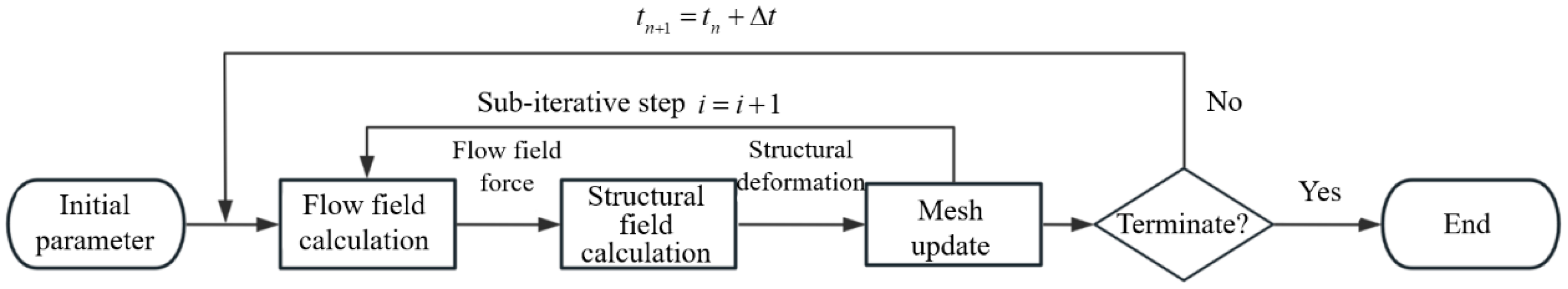
  • Research methods for cross-media water entry: Due to the complexity of cross-media water entry problems, current theoretical studies mostly simplify complex scenarios, and it is difficult to summarize a universally applicable theoretical model that accurately describes the entire physical phenomenon, so further in-depth research is needed. The development of scaled-down test technology has provided a deeper understanding of the complex physical phenomenon of small-size vehicles during high-speed water entry. However, considering the limitations of scaled-down test, it cannot truly restore the real physical phenomenon of full-size model entering water. At present, there are few reports on cross-media water entry tests for full-size models, that can be further improved in the future. In terms of numerical simulation, the monolithic approach can provide high-precision results but faces high computational costs in solving complex and strongly coupled fluid–structure interaction problems. The partitioned approach may also face accuracy and stability issues when dealing with strong coupling and large deformation problems due to its staged iteration process. Future research can focus on improving simulation accuracy, stability, and computational scale.
  • Artificial intelligence in cross-media problems: Artificial intelligence has been preliminarily applied to solving cross-media problems, offering efficient computational speed and high accuracy, thereby providing a novel approach to addressing complex challenges. Currently, AI can predict the load and hydrodynamic properties of vehicles during cross-media processes. In the future, it can be integrated with image recognition technology to further predict flow characteristics, such as the evolution of cavities, in cross-media processes. With the continuous advancement of AI technology, its application prospects in cross-media problems will expand, and it is expected to play an increasingly significant role in fields such as aerospace and ocean engineering.

Author Contributions

Conceptualization, Q.L., X.M. and J.Z.; methodology, Q.L. and X.M.; writing—original draft preparation, Q.L.; writing—review and editing, Q.L., X.M., J.Z. and L.S.; visualization, Q.L., X.M. and J.Z.; supervision, J.Z. and L.S. All authors have read and agreed to the published version of the manuscript.

Funding

This research was funded by the Young Scientists Fund of the National Natural Science Foundation of China, grant number: 12102484.

Data Availability Statement

No new data were created or analyzed in this study. Data sharing is not applicable to this article.

Conflicts of Interest

The authors declare no conflict of interest.

Abbreviations

The following abbreviations are used in this manuscript:
AUVAutonomous Underwater Vehicle
FSIFluid–Structure Interaction
ALEArbitrary Lagrangian-Eulerian
OLMOriginal Logvinovich Method
MLMModified Logvinovich Method
CFDComputational Fluid Dynamics
CSDComputational Structural Dynamics
SMPCShape Memory Polymer Composite
SMPShape Memory Polymer
AIArtificial Intelligence
MLMachine Learning
DNNDeep Neural Network
PNNParallel Neural Network

References

  1. Wang, H.; Huang, Z.; Huang, D.; Hou, Y.; Chen, Z.; Guo, Z.; Sun, S.; Xue, R. Influences of floating ice on the vertical water entry process of a trans-media projectile at high speeds. Ocean Eng. 2022, 265, 112548. [Google Scholar] [CrossRef]
  2. Ming, F.; Wang, J.; Liu, W.; Liu, X.; Zhang, A.M. Review of multiphase flow and fluid-structure interaction of high-speed water entry. Acta Aerodyn. Sin. 2024, 42, 68–85. [Google Scholar] [CrossRef]
  3. Qi, X.; Liu, X.; Wang, R.; Miao, P.; Li, R. Numerical Simulation of Water Entry for High-Speed Projectile at Small Angle. Shipbuild. China 2022, 63, 31–39. [Google Scholar] [CrossRef]
  4. Li, S. Numerical Simulation of Torpedo Water-Entry Impact. Master’s Thesis, North University of China, Taiyuan, China, 2015. [Google Scholar]
  5. Pan, G.; Yang, K. Impact force encountered by waterentry airborne torpedo. Explos. Shock Waves 2014, 34, 521–526. [Google Scholar] [CrossRef]
  6. Sun, S. Study on Trajectory Stability Mechanism of Supercavitating Projectile in Highspeed Water Entry with Small Incident Angle. Ph.D. Dissertation, China Ship Research & Development Academy, Wuxi, China, 2023. [Google Scholar] [CrossRef]
  7. Wei, P.; Hou, J.; Yang, K. Summary of Supercavitating Projectile Researches. Ship Electron. Eng. 2008, 28, 13–17,128. [Google Scholar] [CrossRef]
  8. Meng, Q.; Zhang, Z.; Liu, J.; Gu, J. Research development of high-speed super-cavitating flow of the high-speed underwater vehicle. Ship Ocean Eng. 2006, 35, 26–29. [Google Scholar] [CrossRef]
  9. Yao, Z.; Wang, R.; Xu, B. Research on Current Application State of Supercavitation Projectile Artillery Weapons. J. Gun Launch Control. 2017, 38, 92–96. [Google Scholar] [CrossRef]
  10. Qian, C.; Yu, C.; Mu, Q.; Yi, W.; Guan, J. Numerical Research of Effects of Launch Speed and Launch Angle on Water Entry of High-Speed Projectile. J. Ordnance Equip. Eng. 2019, 40, 35–39, 50. [Google Scholar] [CrossRef]
  11. Qi, H.; Guo, J.; Chu, F.; Wu, H.; Yang, X.; Zhao, H.; Fu, H.; Wang, P. Review on the Fluid-structure Coupling Characteristicsin the Water Entry of Cross-media Vehicles. Aerosp. Shanghai 2024, 41, 74–86. [Google Scholar] [CrossRef]
  12. Zhang, T.; Wang, C.; Xu, H.; Xia, W.; Ma, X.; Zhao, J. Impact Load Characteristics of Large-Scale Trans-Medium Vehicles during High-Speed Oblique Water Entry. J. Unmanned Undersea Syst. 2024, 32, 426–433. [Google Scholar] [CrossRef]
  13. Zhu, Z.; Yuan, X. High-Speed Water-entry Impact and Cavity Characters of Cylinder. Comput. Simul. 2014, 31, 29–33,82. [Google Scholar] [CrossRef]
  14. Qi, X.; Li, X.; Shi, Y.; Wang, R.; Yuan, X. Analysis of Trajectory Characteristics of Shallow Angle Water Entry for High-speed Projectile. Digit. Ocean Underw. Warf. 2023, 6, 293–299. [Google Scholar] [CrossRef]
  15. Yuan, K.; Yu, J.; He, Z.; Yu, H.; Meng, F. Numerical study on the dynamic response of liquid-filled closed hollow cylinder under water impact. Ocean Eng. 2023, 288, 116157. [Google Scholar] [CrossRef]
  16. von Kármán, T. The Impact on Seaplane Floats During Landing; National Advisory Committee for Aeronatics: Washington, DC, USA, 1929. [Google Scholar]
  17. Mirzaei, M.; Taghvaei, H.; Golneshan, A.A. Improvement of cavity shape modeling in water-entry of circular cylinders by considering the cavity memory effect. Appl. Ocean Res. 2020, 97, 102073. [Google Scholar] [CrossRef]
  18. Zheng, C. Study on Trajectory and Load Characteristics of Supercavitating Vehicle During High-Speed Oblique Entry into Water. Master’s Thesis, Harbin Institute of Technology, Harbin, China, 2023. [Google Scholar]
  19. Yuan, X.; Li, M.; Ding, X.; Wei, R.; Zhou, F. Impact Load Characteristics of a Trans-media Vehicle during High-speed Water-entry. Acta Armamentarii 2021, 42, 1440–1449. [Google Scholar] [CrossRef]
  20. Bodily, K.G.; Carlson, S.J.; Truscott, T.T. The water entry of slender axisymmetric bodies. Phys. Fluids 2014, 26, 072108. [Google Scholar] [CrossRef]
  21. Shafaghat, R.; Hosseinalipour, S.M.; Lashgari, I.; Vahedgermi, A. Shape optimization of axisymmetric cavitators in supercavitating flows, using the NSGA II algorithm. Appl. Ocean Res. 2011, 33, 193–198. [Google Scholar] [CrossRef]
  22. Lu, B.; Zhu, Z. Numerical research on load of a super-cavity vehicle with cone-shaped segment at high-speed water-entry. Ship Sci. Technol. 2017, 39, 119–123. [Google Scholar] [CrossRef]
  23. Sharker, S.I.; Holekamp, S.; Mansoor, M.M.; Fish, F.E.; Truscott, T.T. Water entry impact dynamics of diving birds. Bioinspiration Biomim. 2019, 14, 056013. [Google Scholar] [CrossRef]
  24. Wang, T.M.; Yang, X.B.; Liang, J.H.; Yao, G.C.; Zhao, W.D. CFD based investigation on the impact acceleration when a gannet impacts with water during plunge diving. Bioinspiration Biomim. 2013, 8, 036006. [Google Scholar] [CrossRef]
  25. Wu, Z. Bionic Configuration Design and Water Entry Performance of Aquatic UAV Based on Water Entry Strategy of Kingfisher. Ph.D. Dissertation, Jilin University, Changchun, China, 2021. [Google Scholar]
  26. Chen, Y.; Sun, J.; Liu, Y.; Leng, J. Variable stiffness property study on shape memory polymer composite tube. Smart Mater. Struct. 2012, 21, 094021. [Google Scholar] [CrossRef]
  27. Gong, M.; Tao, C.; Zhang, C.; Ji, H.; Qiu, J. A method for regulating negative Poisson’s ratio by a reentrant anti-tetrachiral structure. Mech. Adv. Mater. Struct. 2022, 29, 7399–7414. [Google Scholar] [CrossRef]
  28. Huang, X.; Liu, B. Current situation and development of warship structure material. Ship Boat 2004, 3, 21–24. [Google Scholar] [CrossRef]
  29. Huang, D. Application and Development of New Material in Modern Torpedo Technology. Torpedo Technol. 2004, 12, 1–3. [Google Scholar]
  30. Zhang, M.; Sun, S.; Feng, D. Application and Development of New Materials in Torpedo Designs. Torpedo Technol. 2015, 23, 86–89,118. [Google Scholar] [CrossRef]
  31. Wang, S.; Guo, J.; Chao, Q.; Bian, M.; Tian, S. Modeling and Simulation Analysis of Torpedo’s Water-Entry Impact Based on CEL Algorithm. J. Unmanned Undersea Syst. 2020, 28, 75–80. [Google Scholar] [CrossRef]
  32. He, Z.; Gao, Z.; Gu, X.; Gao, Z. Numerical simulation on the structural response of a torpedo at the moment of vertical water entry. Explos. Shock Waves 2023, 43, 144–158. [Google Scholar] [CrossRef]
  33. Han, M. Vibration Analysis of Supercavitating Body with Tail Slap and Damping Structural Design. Master’s Thesis, Harbin Engineering University, Harbin, China, 2014. [Google Scholar]
  34. Guo, J.; Han, J.; Li, X.; Lu, C.; Jiang, P.; Lv, Z. Reseach of Modeling and Simulation of Airdrop Torpedo Parachute System Based on Six Free Degrees. Ship Electron. Eng. 2022, 42, 124–128. [Google Scholar] [CrossRef]
  35. Li, B. Preliminary Discussion of Torpedo Parachute. Torpedo Technol. 2004, 12, 37–40. [Google Scholar]
  36. Jiang, L.; Jia, H.; Xu, X.; Rong, W.; Wang, Q.; Chen, G.; Fan, J.; Xue, X. Effect of Different Geometric Porosities on Aerodynamic Characteristics of Supersonic Parachutes. Space Sci. Technol. 2023, 3, 0062. [Google Scholar] [CrossRef]
  37. Pan, L.; Wang, H.; Yao, E.; Wang, X. Mechanism Research on the Water-Entry Impact of the Head-Jetting Flat Cylinder. J. Eng. Thermophys. 2015, 36, 1691–1695. [Google Scholar]
  38. Gao, Z. Numerical Study on the Buffering Characteristics of Low-Speed Water Entry for the Head-Jetting Vehicle. Master’s Thesis, Harbin Engineering University, Harbin, China, 2023. [Google Scholar]
  39. Liu, H.; Yu, F.; Han, B.; Zhang, Y.; Liu, G.; Chen, H. Numerical Simulation Study on Influence of Top Jet in Object Water Entering Impact. J. Eng. Thermophys. 2019, 40, 300–305. [Google Scholar]
  40. Zou, Z.; Li, J.; Yang, M.; Liu, H.; Jiang, Y. Experimental Investigation on Cavity Flow Characteristics of Water Entry of Vehicle With Gas Jet Cavitator. J. Ballist. 2022, 34, 1–8,97. [Google Scholar] [CrossRef]
  41. Wei, H.; Xin, W.; Liu, H.; Liu, Y. Research on the Influence of Different Nozzle Structures on the Impact of High-Speed Water-Entry Vehicles. Astronaut. Syst. Eng. Technol. 2021, 5, 41–46,53. [Google Scholar]
  42. Peng, R.; Feng, H.; Xiang, M.; Peng, Y. Effect of head jet on load characteristics of a transdielectric vehicle during water entry. Ship Sci. Technol. 2024, 46, 59–66. [Google Scholar] [CrossRef]
  43. Shi, Y.; Gao, X.-F.; Pan, G. Design and load reduction performance analysis of mitigator of AUV during high speed water entry. Ocean Eng. 2019, 181, 314–329. [Google Scholar] [CrossRef]
  44. Zheng, W.; Li, Q.; Fan, X.; Lv, X. Review of the Development on Load Reduction Methods for Water Entry of High-Speed Vehicles. J. Unmanned Undersea Syst. 2024, 32, 411–425. [Google Scholar] [CrossRef]
  45. Xu, X.; Li, J.; Cao, X.-J. Water-Entry Impact Performance of Torpedo′s Cushion Nose Cap. Torpedo Technol. 2012, 20, 161–165,170. [Google Scholar] [CrossRef]
  46. Yan, Z. An Approach to the Behavior of water-entry missile’s mitigator. Chin. J. Hydrodyn. 1987, 1, 112–121. [Google Scholar]
  47. Wang, Y.; Shi, X.; Wang, P. Exploring Analysis of Dynamic Cushioning Properties of Water-Entry Missile’s Shock Mitigator. J. Northwestern Polytech. Univ. 2009, 27, 707–712. [Google Scholar] [CrossRef]
  48. Wei, H.; Shi, C.; Sun, T.; Bao, W.; Zhang, G. Numerical study on load-shedding performance of a high-speed water-entry vehicle based on an ALE method. Explos. Shock Waves 2021, 41, 112–123. [Google Scholar] [CrossRef]
  49. Shi, Y.; Liu, Z.; Pan, G.; Gao, X. Structural design and load reduction performance analysis of gradient density head cap of vehicle. Chin. J. Theor. Appl. Mech. 2022, 54, 939–953. [Google Scholar] [CrossRef]
  50. Yao, X.; Yang, Z.; Ma, G.; Chen, Y.; Yin, Q.; Kong, D.; Sun, L.; Fan, S.; Fang, M. Research on the characteristics and similarity relationships of impact load reduction of a vehicle entering water. Appl. Ocean Res. 2024, 142, 103814. [Google Scholar] [CrossRef]
  51. Li, Y.; Zong, Z.; Sun, T. Crushing behavior and load-reducing performance of a composite structural buffer during water entry at high vertical velocity. Compos. Struct. 2021, 255, 112883. [Google Scholar] [CrossRef]
  52. Li, Y.; Zong, Z.; Sun, T. Classification of the collapse of a composite fairing during the oblique high-speed water entry. Thin-Walled Struct. 2023, 182, 110260. [Google Scholar] [CrossRef]
  53. Sui, Y. Study on the Fluid-Structure Coupling Load Characteristics of the Water Entry of the Projectiles with Different Nose Shapes. Ph.D. Dissertation, Harbin Engineering University, Harbin, China, 2023. [Google Scholar]
  54. Liu, H. Study on Load Reduction of Revolved Body Entering Water at High Speed. Master’s Thesis, Harbin Engineering University, Harbin, China, 2021. [Google Scholar]
  55. Sui, Y.-T.; Ming, F.-R.; Wang, S.-P.; Han, R. Experimental investigation on the impact force of the oblique water entry of a slender projectile with spring buffer. Appl. Ocean Res. 2023, 138, 103631. [Google Scholar] [CrossRef]
  56. Fu, Z.; Sun, L.; Zhi, M.; Wang, P.; Wang, D. Numerical study on the dynamic characteristics of a vehicle with a multistage load reduction structure during oblique water entry. Ocean Eng. 2024, 295, 116778. [Google Scholar] [CrossRef]
  57. Zhi, M.; Li, Z.; Sun, L.; Wang, D. Investigation and optimization of load characteristics of a multi-stage load-reduction structure for vehicles during high-speed vertical water entry. Ocean Eng. 2023, 289, 116183. [Google Scholar] [CrossRef]
  58. Wang, Y. Study on Load Reduction of Projectile with High Speed. Master’s Thesis, Harbin Engineering University, Harbin, China, 2022. [Google Scholar]
  59. May, A. Water Entry and the Cavity-Running Behavior of Missiles. J. Fluid Mech. 1975, 1, 123–145. [Google Scholar] [CrossRef]
  60. Zhou, K.; Huang, Z.; Chen, Z.; Liu, X.; Wang, H. Ricochet Phenomenon of Tans-media Vehicle at High-speed Oblique Water-entry. Equip. Environ. Eng. 2022, 19, 39–48. [Google Scholar] [CrossRef]
  61. Liu, X.; Luo, K.; Yuan, X.; Ren, W. Influence of Expansion Sterns on the Flattening Trajectory Characteristics of a Trans-Media Vehicle During High-Speed Water Entry. Chin. J. Theor. Appl. Mech. 2023, 55, 343–354. [Google Scholar] [CrossRef]
  62. Yu, F. The Numerical Simulation Study of Whipping Performance in Water Entry of Navigation Body. Master’s Thesis, Harbin Institute of Technology, Harbin, China, 2019. [Google Scholar]
  63. Yan, Z. The Technology of Stabilization of Initial Trajectory of Water-entry Torpedoes. Chin. J. Hydrodyn. 1990, 5, 117–126. [Google Scholar] [CrossRef]
  64. Wang, Y.; Shi, X. Numerical Analysis for Initial Hydroballistics of Airborne Missile During Oblique Water-entry Impact. J. Ballist. 2012, 24, 92–95. [Google Scholar] [CrossRef]
  65. Zhang, Y.; Cai, W.; Li, J.; Li, Z.; Pang, D. Simulation on Whip Phenomenon of Torpedo during Oblique Water Entry. J. Unmanned Undersea Syst. 2018, 26, 146–151. [Google Scholar] [CrossRef]
  66. Xu, X. Investigation of Water Entry Trajectory of Torpedo. Torpedo Technol. 2004, 12, 29–31. [Google Scholar]
  67. Ruzzene, M.; Kamada, R.; Bottasso, C.L.; Scorcelletti, F. Trajectory Optimization Strategies for Supercavitating Underwater Vehicles. J. Vib. Control. 2008, 14, 611–644. [Google Scholar] [CrossRef]
  68. Kirschner, I.N.; Rosenthal, B.J.; Uhlman, J.S. Simplified Dynamical Systems Analysis of Supercavitating High-Speed Bodies. In Proceedings of the Fifth International Symposium on Cavitation, Osaka, Japan, 1–4 November 2003. [Google Scholar]
  69. Yuan, X.; Zhu, Z. Influence of preset rudder angle on trajectory and hydro-dynamic at high-speed water-entry. Chin. J. Appl. Mech. 2015, 1, 11–16. [Google Scholar] [CrossRef]
  70. Liu, X.; Yuan, X.; Luo, K.; Qi, X. Experimental Investigation of the Influence of Preset Rudder Angle on Tail-slapping of a Transmedia Vehicle during Water Entry. Acta Armamentarii 2023, 44, 1632–1642. [Google Scholar] [CrossRef]
  71. Liu, X.; Yuan, X.; Luo, K.; Lu, N. Experiments and Simulation of Continuous Water Entry and Exit Trajectories of a Trans-media Vehicle. Acta Armamentarii 2023, 44, 1225–1236. [Google Scholar] [CrossRef]
  72. Huang, B.; Li, D.; Huang, C.; Gu, J.; Luo, K. Effect of Material Density on the Tail-slapping Characteristics of Supercavitating Projectiles. J. Unmanned Undersea Syst. 2023, 31, 211–220. [Google Scholar] [CrossRef]
  73. Miloh, T.; Shukron, Y. Ricochet Off Water of Spherical Projectiles. J. Ship Res. 1991, 35, 91–100. [Google Scholar] [CrossRef]
  74. Hutchings, I.M. The ricochet of spheres and cylinders from the surface of water. Int. J. Mech. Sci. 1976, 18, 243–247. [Google Scholar] [CrossRef]
  75. Park, M.-S.; Jung, Y.-R.; Park, W.-G. Numerical study of impact force and ricochet behavior of high speed water-entry bodies. Comput. Fluids 2003, 32, 939–951. [Google Scholar] [CrossRef]
  76. Wang, Z.; Feng, P.; Liu, G.; Zhao, X.; Qin, X. Load and motion behaviors of ogive-nosed projectile during high-speed water entry with angle of attack. Ocean Eng. 2022, 266, 112937. [Google Scholar] [CrossRef]
  77. Li, Q.; Lu, L.; Cai, T. Numerical investigations of trajectory characteristics of a high-speed water-entry projectile. AIP Adv. 2020, 10, 095107. [Google Scholar] [CrossRef]
  78. Qi, X.; Shi, Y.; Liu, X.; Pan, G. Study on trajectory characteristics of stepped cylindrical projectile entering water at small angle. Chin. J. Theor. Appl. Mech. 2023, 55, 2468–2479. [Google Scholar] [CrossRef]
  79. Sui, Y.-T.; Li, S.; Ming, F.-R.; Zhang, A.M. An experimental study of the water entry trajectories of truncated cone projectiles: The influence of nose parameters. Phys. Fluids 2022, 34, 052102. [Google Scholar] [CrossRef]
  80. Huang, H.; Zhang, H.; Wei, J.; Zhang, F. Stability Analysis of High-Speed Water Entry of Different Structure Projectiles. J. Ordnance Equip. Eng. 2019, 40, 50–54. [Google Scholar] [CrossRef]
  81. Song, B.; Du, X.; Meng, R.; Li, J.; Shao, C. Numerical Simulation of Water-entry Impact Force for Air-launched Mine. Torpedo Technol. 2008, 16, 6–8,12. [Google Scholar] [CrossRef]
  82. Wagner, H. Phenomena associated with impacts and sliding on liquid surfaces. ZAMM—J. Appl. Math. Mech./Z. Für Angew. Math. Und Mech. 1932, 12, 193–215. [Google Scholar] [CrossRef]
  83. Logvinovich, G.V. Hydrodynamics of Flows with Free Boundaries; Institute for Physical Science and Technology: College Park, MD, USA, 1969. [Google Scholar]
  84. Korobkin, A. Analytical models of water impact. Eur. J. Appl. Math. 2004, 15, 821–838. [Google Scholar] [CrossRef]
  85. Dobrovol’skaya, Z.N. On some problems of similarity flow of fluid with a free surface. J. Fluid Mech. 1969, 36, 805–829. [Google Scholar] [CrossRef]
  86. Chen, C.; Sun, T.; Wei, Y.; Wang, C. Computational analysis of compressibility effects on cavity dynamics in high-speed water-entry. Int. J. Nav. Archit. Ocean Eng. 2019, 11, 495–509. [Google Scholar] [CrossRef]
  87. Li, G.; You, T.; Kong, D.; Li, J.; Zhou, W. Effect of Fluid Compressibility on High-speed Water-entry of Revolutionary Body. Acta Armamentarii 2020, 41, 720–729. [Google Scholar] [CrossRef]
  88. Egorov, L.T. Impact on a Compressible Fluid; National Advisory Committee for Aeronautics: Washington, DC, USA, 1958. [Google Scholar]
  89. Borg, S.F. Initial Wedge Impact on a Compressible Fluid. J. Appl. Phys. 1959, 30, 1432–1436. [Google Scholar] [CrossRef]
  90. Korobkin, A.A. Asymptotic Theory of Liquid--Solid Impact. Philos. Trans. Math. Phys. Eng. Sci. 1997, 355, 507–522. [Google Scholar] [CrossRef]
  91. Rayleigh, L. On the pressure developed in a liquid during the collapse of a spherical cavity. Lond. Edinb. Dublin Philos. Mag. J. Sci. 1917, 34, 94–98. [Google Scholar] [CrossRef]
  92. Plesset, M.S. The Dynamics of Cavitation Bubbles. J. Appl. Mech. 2021, 16, 277–282. [Google Scholar] [CrossRef]
  93. Garabedian, P.R. Calculation of axially symmetric cavities and jets. Pac. J. Math. 1956, 6, 611–684. [Google Scholar] [CrossRef]
  94. Truscott, T.T. Cavity Dynamics of Water Entry for Spheres and Ballistic Projectiles. Ph.D. Dissertation, Massachusetts Institute of Technology, Cambridge, MA, USA, 2009. [Google Scholar]
  95. Aldape, K.; Zadeh, G.; Mansouri, S.; Reifenberger, G.; von Deimling, A. Glioblastoma: Pathology, molecular mechanisms and markers. Acta Neuropathol. 2015, 129, 829–848. [Google Scholar] [CrossRef]
  96. Lundstrom, E.A.; Fung, W.K. Fluid Dynamic Analysis of Hydraulic Ram III (Result of Analysis); NASA STI/Recon Technical Report N: Washington, DC, USA, 1976. [Google Scholar]
  97. Lee, M.; Longoria, R.G.; Wilson, D.E. Cavity dynamics in high-speed water entry. Phys. Fluids 1997, 9, 540–550. [Google Scholar] [CrossRef]
  98. Zhang, W. Study on Fluid-structure Interactions Characteristics and Similarity Analysis of HighSpeed Navigation Body Enter Water. Master’s Thesis, Harbin Engineering University, Harbin, China, 2023. [Google Scholar]
  99. Stinebring, D.; Billet, M.; Lindau, J.; Kunz, R. Developed Cavitation-Cavity Dynamics. VKI Spec. Course Supercavitating Flows 2001, 29. [Google Scholar]
  100. Xu, H.; Luo, K.; Huang, C.; Zuo, Z.; Gu, J. Variation Characteristics of Formation and Development of Ventilated Supercavity at Low Froude Numbers. J. Shanghai Jiaotong Univ. 2021, 55, 934–941. [Google Scholar] [CrossRef]
  101. Waugh, J.G. Water-entry pitch modeling (Water entry pitch modeling using Froude and cavitation number scaling with and without gas density scaling, using dummy Mk 25 aircraft torpedoes). J. Hydronautics 1968, 2, 87–92. [Google Scholar] [CrossRef]
  102. Qi, D.; Feng, J.; Xu, B.; Zhang, J.; Li, Y. Investigation of water entry impact forces on airborne-launched AUVs. Eng. Appl. Comput. Fluid Mech. 2016, 10, 473–484. [Google Scholar] [CrossRef]
  103. Korobkin, A.; Guéret, R.; Malenica, Š. Hydroelastic coupling of beam finite element model with Wagner theory of water impact. J. Fluids Struct. 2006, 22, 493–504. [Google Scholar] [CrossRef]
  104. Hao, C.; Dang, J.; Chen, C.; Huang, C. Numerical study on water entry process of supercavitating projectile by considering bidirectional fluid structure interaction effect. Chin. J. Theor. Appl. Mech. 2022, 54, 678–687. [Google Scholar] [CrossRef]
  105. Wu, Q. Physical and Numerical Investigation of Cavitating Flow-Induced Vibrations. Ph.D. Dissertation, Beijing Institute of Technology, Beijing, China, 2016. [Google Scholar]
  106. Ryzhakov, P.B.; Rossi, R.; Idelsohn, S.R.; Oñate, E. A monolithic Lagrangian approach for fluid–structure interaction problems. Comput. Mech. 2010, 46, 883–899. [Google Scholar] [CrossRef]
  107. Deng, C. The Algorithm Study of Weak Coupling in Fluid-Structure Interaction. Master’s Thesis, Huazhong University of Science and Technology, Wuhan, China, 2012. [Google Scholar]
  108. Xu, Y.; Tan, D.; Yang, C. Study on tail-slap load characteristics of high-speed projectile based on CFD/CSD coupling. J. Beijing Univ. Aeronaut. Astronaut. 2023, 49, 2539–2546. [Google Scholar] [CrossRef]
  109. Gao, Y. Numerical Analysis of Impact Load and Flow Characteristics of High Speed Water-Entry for a Revolution Body Based on a Fluid-Structure Interaction Method. Master’s Thesis, Dalian University of Technology, Dalian, China, 2020. [Google Scholar]
  110. Shi, Y.; Pan, G.; Yim, S.C.; Yan, G.; Zhang, D. Numerical investigation of hydroelastic water-entry impact dynamics of AUVs. J. Fluids Struct. 2019, 91, 102760. [Google Scholar] [CrossRef]
  111. Wei, T.; Li, J.; Zeng, Z.; Lian, L. Trans-media resistance investigation of hybrid aerial underwater vehicle base on hydrodynamic experiments and machine learning. Ocean Eng. 2022, 266, 112808. [Google Scholar] [CrossRef]
  112. Lv, K.; Lin, E.; Liu, Y.; Chen, Z.; Wang, Y.; He, M.; Yan, J.; Lv, P.; Yang, Y.; Li, H.; et al. Data-driven optimization of nose profiles for water entry impact load reduction. Ocean Eng. 2025, 315, 119851. [Google Scholar] [CrossRef]
  113. Huang, X.; Li, Z.; Dai, Y.; Zhu, X. Application of parallel neural networks (PNN) in predicting and analyzing vehicle attitude during the water exit process. Ocean Eng. 2025, 323, 120602. [Google Scholar] [CrossRef]
  114. Zhang, S.; Xu, H.; Sun, T.; Duan, J. Water-exit dynamics of a ventilated underwater vehicle in wave environments with a combination of computational fluid dynamics and machine learning. Phys. Fluids 2024, 36, 023312. [Google Scholar] [CrossRef]
Figure 1. Water entry cavity evolution and impact loads of three types of vehicles.
Jmse 13 00703 g001
Figure 2. Water entry process of high-speed projectiles with different head types.
Jmse 13 00703 g002
Figure 3. Simplified computational model of double-layer vibration-damped shell structure.
Jmse 13 00703 g003
Figure 4. Air-dropped torpedo deploying parachute into the water.
Jmse 13 00703 g004
Figure 5. Water entry process of air jet load reduction action.
Jmse 13 00703 g005
Figure 6. Buffer headcap structure.
Jmse 13 00703 g006
Figure 7. Vehicles with spring or air chamber cushion: (a) spring structure; (b) air chamber cushioning structure.
Jmse 13 00703 g007
Figure 8. Whip phenomenon of air-dropped torpedoes.
Jmse 13 00703 g008
Figure 9. Ricochet phenomenon of high-speed projectiles.
Jmse 13 00703 g009
Figure 10. Monolithic approach.
Jmse 13 00703 g010
Figure 11. Loosely coupled algorithm.
Jmse 13 00703 g011
Figure 12. Tightly coupled algorithm.
Jmse 13 00703 g012
Table 1. The structural characteristics, water entry states, and main research issues of the three types of vehicles.
TypesStructural CharacteristicsWater Entry StatesLoad Impact ProblemBallistic Stability Problem
Air-dropped torpedoesBlunt-nosed thin-shell structure (~100 mm diameter [4]) with integrated precision electronics.Speed: Tens of m/s;
Large water entry angle: usually >70° [4].
The problems of head structural damage and internal electronics damage.The whip problem.
Supercavitating vehiclesLarge-scale thin-shell structure (~100 mm diameter [6]) in conical shape with cavitator.Speed: Hundreds of m/s;
Small water entry angle: usually 10°~45° [7].
The problems of thin body structure fracture.The flat-turning problem.
High-speed projectilesConical compact rigid-body design (~10 mm diameter [8]). Speed: Hundreds to thousands of m/s;
Minimal water entry angle [9].
The problems of structural bending.The ricochet
problem.
Table 2. Mechanisms and types of application of active load shedding methods.
Active Load Reduction MethodsLoad Reduction MechanismsTypes of Applicable Vehicles
ParachuteOpening the parachute increases the drag force, reduces the water entry speed, and prolongs the water impact time.Air-dropped torpedoes
Air jetThe air jet creates an air cushion effect, making the peak pressure far away from the bow of the vehicle and prolonging the water impact action time.High-speed projectiles,
supercavitating vehicles
Buffer headcapThe elastic material prolongs the water impact action time, absorbs strong impact energy and undergoes gradual compression, failure, and destruction until it detaches from the vehicle.Air-dropped torpedoes
Spring, air chamber, and
its composite structures
The buffer structure prolongs the water impact action time, absorbs the impact energy, and slowly releases it to the vehicle.High-speed projectiles,
supercavitating vehicles
Table 3. Main theoretical researchers at different stages and their contributions.
Research AspectsResearch PhaseMain Theoretical ResearchersResearch Achievements and Contributions
Water-
entry
impact load
Early
Studies
Von KarmanIntroduced the “added mass” concept and applied momentum conservation to calculate water impact pressure during seaplane landings.
WagnerDeveloped approximate flat-plate theory by considering free surface elevation and introducing a correction factor for small deadrise angles. Extended the model for wedge-shaped bodies.
Egorov, BorgInvestigated blunt-body impacts on compressible fluids, proposed time-scale formulas for compressibility effects (related to sound speed in water).
Subsequent DevelopmentsLogvinovichProposed the Original Logvinovich Method (OLM), incorporating nonlinear terms in the Bernoulli equation and added velocity terms at solid–liquid contact points. Improved modeling of shockwave propagation and liquid separation.
Dobrovol’skayaApplied self-similarity theory to transform free surface flow problems into nonlinear singular integral equations, providing tools for solving complex free surface flows.
Further improvementKorobkinDeveloped the Modified Logvinovich Method (MLM), refining nonlinear terms and velocity treatments. Enabled simulations for complex geometries, motions, and flow conditions.
Refined the cross-media water entry process into five stages: supersonic, transonic, subsonic, inertial, and developed flow stages.
Evolution of water-
entry cavity
Early StudiesRayleigh &
Plesset
Formulated the Rayleigh–Plesset equation, describing the kinetic behavior of cavitation bubbles under the influence of pressure changes, viscosity, and surface tension.
GarabedianDerived asymptotic expressions for cavity width, length, and parameters (Garabedian formula) using perturbation methods for axisymmetric free surface flows.
LogvinovichProposed the “independence principle of cavity section expansion”, enabling theoretical calculations of unsteady cavity evolution by decomposing cavity morphology.
Subsequent developmentLundstromDerived an empirical formula for cavity radius based on energy conservation, summarizing cavity shape evolution laws for cross-media water entry vehicles.
LeeProposed a universal cavity evolution model applicable to arbitrary shapes and velocities, predicting closure time and position accurately.
Further improvementTruscottImproved Logvinovich’s model with full-scale experiments, analyzing effects of velocity, geometry, and angle of attack on cavity formation. Optimized vehicle shape design.
VasinApplied Logvinovich’s theory to analyze unsteady cavity dynamics and external pressure changes, including gravity effects on cavity shape.
Table 4. Common dimensionless similarity parameters in scaled-down experimental designs.
Similarity ParameterExpressionPhysical MeaningExplicit Value
Froude Number (Fr) F r = V g L Ratio of inertial forces to gravitational forces71.4
Cavitation Number (σ) σ = p p v 1 2 ρ V 2 Ratio of static pressure to dynamic pressure0.0198
Reynolds Number (Re) R e = ρ V L μ Ratio of inertial forces to viscous forces2.0 × 107
Weber Number (We) W e = ρ V 2 L σ Ratio of inertial forces to surface tension forces
( σ 0.0728   N / m , the surface tension coefficient)
2.74 × 10⁷
Capillary Number (Ca) C a = μ V σ Ratio of viscous forces to surface tension forces
( σ 0.0728   N / m , the surface tension coefficient)
1.376
Mach Number (Ma) M a = V c Ratio of fluid velocity to speed of sound
( c 1482   m / s , the speed of sound in water)
0.067
Disclaimer/Publisher’s Note: The statements, opinions and data contained in all publications are solely those of the individual author(s) and contributor(s) and not of MDPI and/or the editor(s). MDPI and/or the editor(s) disclaim responsibility for any injury to people or property resulting from any ideas, methods, instructions or products referred to in the content.

