Abstract
With the increasing severity of global environmental issues and the pressure from the strict pollutant emission regulations proposed by the International Maritime Organization (IMO), the shipping industry is seeking new types of marine power systems that can replace traditional propulsion systems. Marine fuel cells, as an emerging energy technology, only emit water vapor or a small amount of carbon dioxide during operation, and have received widespread attention in recent years. However, research on their application in the shipping industry is relatively limited. Therefore, this paper collects relevant reports and literature on the use of fuel cells on ships over the past few decades, and conducts a thorough study of typical fuel cell-powered vessels. It summarizes and proposes current design schemes and optimization measures for marine fuel cell power systems, providing directions for further improving battery performance, reducing carbon emissions, and minimizing environmental pollution. Additionally, this paper compares and analyzes marine fuel cells with those used in automotive, aviation, and locomotive applications, offering insights and guidance for the development of marine fuel cells. Although hydrogen fuel cell technology has made significant progress in recent years, issues still exist regarding hydrogen production, storage, and related safety and standardization concerns. In terms of comprehensive performance and economics, it still cannot effectively compete with traditional internal combustion engines. However, with the continued rapid development of fuel cell technology, marine fuel cells are expected to become a key driver for promoting green shipping and achieving carbon neutrality goals.
1. Introduction
Shipping plays a pivotal role in the global economy as one of the primary modes of international trade and the world’s largest logistics method, connecting markets across the globe. Through ocean shipping, goods can be transported over long distances at low cost and in bulk, supporting the operation of global supply chains. As a vital transport tool in the global shipping industry, ships hold an indispensable position.
However, with the growing environmental challenges, particularly climate change, the shipping industry faces increasingly stringent emission standards and environmental pressures. According to statistics, shipping activities account for nearly 2.5–3% of global carbon dioxide emissions, and over 5% of sulfur oxide emissions. Consequently, shipping is a major source of greenhouse gases, air pollutants, nitrogen oxides, and sulfur oxides [1,2]. According to the International Maritime Organization (IMO), the global shipping industry aims to reduce CO emissions by 60% by 2030 compared to 2008 levels and to achieve zero greenhouse gas emissions in shipping by 2050, as well as to meet clear regulations in the International Convention for the Prevention of Pollution from Ships regarding fuel sulfur and nitrogen content [3,4]. This necessitates technical improvements in the energy efficiency of ship power systems and the promotion of sustainable development through green shipping and low-carbon vessels.
Traditional ship propulsion systems mainly rely on the combustion of fossil fuels, particularly heavy oil and diesel, due to their high energy density and relatively low cost, which have long made them the primary choice for ship power systems. However, their combustion process releases large amounts of carbon dioxide, nitrogen oxides, and sulfur oxides, contributing to air pollution, global warming, ocean acidification, and ecological damage.
Marine fuel cells, as an emerging energy technology, have gained widespread attention in recent years. Fuel cells generate electrical energy through electrochemical reactions using hydrogen or other fuels, with emissions consisting only of water vapor and a small amount of carbon dioxide, offering significant environmental advantages. Compared to traditional diesel engines, fuel cells not only greatly reduce emissions from ships but also significantly improve energy efficiency. Especially in the context of increasingly stringent carbon emission requirements in the future shipping industry, fuel cell technology is considered one of the key pathways to achieving zero emissions and green shipping [5].
Hydrogen energy, as a secondary energy carrier with a wide range of sources, high conversion efficiency, and broad application scenarios, has seen groundbreaking developments in various countries. In the United States, Japan, and Europe, hydrogen energy development is regarded as a national energy strategy, with detailed development plans in place. These include the establishment of hydrogen energy infrastructure, research on fuel cell key technologies, and industrial applications of fuel cells [6,7]. China has also been continuously introducing relevant policies to promote the application of hydrogen fuel cells in the shipping sector.
Although fuel cells show tremendous potential in the shipping field, their application still faces many technical and economic challenges. Issues such as fuel cell energy density, durability, hydrogen storage, and transportation continue to limit their widespread application in ship propulsion systems [8].
This article will delve into the latest research developments in ship fuel cell technology, analyze case studies of fuel cell-powered vessels that have been built or are under construction, and evaluate their technological advantages and potential issues in ship propulsion systems. By comparing the applications of fuel cells in the automotive, aviation, and military sectors, the article aims to provide theoretical support and practical guidance for the green transformation of the shipping industry.
2. Brief Introduction of Fuel Cell Technology
Fuel cell technology, regarded as a leading contender among the fourth generation of power generation technologies, is unique in that its thermal efficiency surpasses the theoretical limit of the Carnot cycle. Under specific load conditions, the efficiency of fuel cells can be two to three times higher than that of traditional internal combustion engines. Fuel cells can directly convert chemical energy into electrical energy without the need for combustion or mechanical movement as intermediate steps.
2.1. Working Principle of Fuel Cell
The working principle of fuel cells is similar to that of traditional batteries, but their operational mechanisms differ. Traditional batteries integrate the dual functions of energy storage and conversion, where electroactive materials are typically embedded as part of the electrode structure. During operation, the stored energy materials are gradually consumed [9]. In contrast, fuel cell is merely an energy conversion device and does not store energy. Depending on the power rating, fuel cells can operate at power levels ranging from the milliwatt level to the megawatt level. Moreover, the power and capacity can be scaled as needed, allowing for better adjustment of energy density [10]. A schematic diagram of the fuel cell structure is provided in Figure 1.
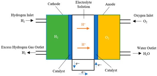
Figure 1.
Proton Exchange Membrane Fuel Cell structure diagram.
2.2. Basic Characteristics of Fuel Cell
- (1)
- High efficiency
Traditional internal combustion engines generate thermal energy through the combustion of fuel, which is then converted into mechanical energy through mechanical transmission. During this process, a large amount of energy is lost in the form of heat, resulting in overall efficiency typically ranging from 20% to 30% [11]. In contrast, fuel cells operate based on electrochemical reactions, directly converting fuel and oxygen into electrical energy and water, thus avoiding the energy loss associated with heat conversion during combustion. This results in higher conversion efficiency, which can reach 40% to 60% [12,13].
- (2)
- Low Pollution
The low pollution of fuel cells is mainly reflected in their clean energy conversion process. Fuel cells do not involve a combustion process. When using green hydrogen as fuel, the only byproducts of the fuel cell reaction are water and a small amount of heat, with almost no harmful gases such as sulfur oxides, nitrogen oxides, and other atmospheric pollutants, significantly reducing air pollution and greenhouse gas emissions [14].
- (3)
- Low Noise
Unlike traditional internal combustion engines, fuel cells operate through electrochemical reactions, a process that is very smooth without the violent movement of components such as pistons and crankshafts and does not involve the rapid expansion of high-pressure gases or combustion explosions. Additionally, the cooling system of fuel cells typically uses liquid cooling or air cooling, but the noise from these cooling systems is usually much quieter compared to the fan noise in internal combustion engines [15].
- (4)
- Wide Application and Flexibility
Fuel cells are generally designed and manufactured using a modular structure. Multiple basic units form a fuel cell stack, and multiple stacks form a power generation module. The battery modules can be flexibly designed based on different customer needs. Furthermore, fuel cells are suitable for applications in electric vehicles and public transportation, offering longer driving ranges and shorter refueling times compared to traditional lithium battery vehicles [16].
2.3. Fuel Cell Type
Fuel cells can be classified into Proton Exchange Membrane Fuel Cells (PEMFCs), Alkaline Fuel Cells (AFCs), Phosphoric Acid Fuel Cells (PAFCs), Solid Oxide Fuel Cells (SOFCs), and Molten Carbonate Fuel Cells (MCFCs), based on the type of ionic conductor and operating temperature. Among these, PEMFCs and SOFCs have attracted considerable attention in the maritime industry due to their outstanding performance and have achieved significant success in commercial applications.
PEMFCs use PEM to conduct hydrogen ions. LTPEMFCs have made significant progress in recent decades. However, the unique wet solid polymer membrane requires maintaining a humid state at operating temperatures of 60–80 °C, which increases the complexity of water management. The emergence of HTPEMFCs has provided new ideas to address this issue. It not only inherits the high-power and high-efficiency advantages of PEMFCs but also, due to its high-temperature operating characteristics, reduces the requirements for hydrogen purity, making it more suitable for complex environments such as ships [17,18]. PAFCs use H3PO4 as the electrolyte. The operating temperature is between 150 and 200 °C, which reduces the dependence on platinum catalysts and improves the fuel’s tolerance to CO. Over the long-term operation of PAFC, its output performance inevitably declines, especially under high operating temperatures and high electrode potentials, where the battery performance decreases faster [19]. Therefore, research is needed to address issues such as platinum catalyst microcrystallization and carrier corrosion, develop cooling methods to ensure uniform battery temperature distribution, and find ways to avoid high electrode potentials when the battery operates under low load or idle conditions [20]. AFCs use a strong alkaline solution as the electrolyte, making the anti-corrosion requirements for the battery components lower. Additionally, in alkaline conditions, non-precious metal electrocatalysts such as nickel or silver exhibit activity comparable to precious metal Pt catalysts, allowing alkaline fuel cell systems to potentially use entirely non-precious metal catalysts [21]. SOFCs primarily use solid conductive ceramics as the electrolyte to conduct oxygen ions generated at the cathode [22]. SOFCs can operate in conjunction with gas turbines to achieve an energy efficiency of over 70%, making it an ideal choice for auxiliary or main power on ships [23]. MCFCs are high-temperature fuel cells that use molten carbonate as the electrolyte. Under high-temperature conditions, the carbonate electrolyte generates electricity by conducting carbonate ions. MCFCs can use nickel (Ni) as the structural material for the battery, which is readily available and inexpensive, and it has relatively low requirements for fuel purity. It also allows for internal fuel reforming within the cell. Table 1 introduces the relevant parameters of these five typical fuel cells [24,25].

Table 1.
Introduction of five types of fuel cells [17,18,20,21,22,23,24,26,27,28,29,30,31,32].
3. Research Progress of Marine Fuel Cell Technology
This chapter will explore the practical applications of fuel cells in the maritime sector. Compared to traditional ship propulsion systems, such as diesel engines and gas turbines, fuel cell technology demonstrates numerous advantages, including high energy efficiency, low noise, vibration-free operation, and zero pollution. These characteristics have made it a focal point of significant attention from countries around the world and the shipping industry.
3.1. Overview of Marine Fuel Cell Technology
According to a market research report by the German Lloyd’s Register, the global marine fuel cell market holds tremendous potential, with an estimated market capacity of 160 GW [33]. At the same time, experts from the European Union have stated that by 2025, hydrogen-powered ships will account for 2% of the total ships in EU member states. The renowned maritime research institution Clarkson predicts that by 2050, hydrogen-powered vessels will account for 40% of alternative energy ships. Zeng Hui, the Director of the Business Planning Department of the China Shipbuilding Seventh Research Institute, also mentioned that based on domestic shipping statistics from the Ministry of Transport, with 1% of ships (such as cargo ships, container ships, and passenger ships under 10 years old) to be retrofitted and 2% of new ships to be built by 2025, it is estimated that the domestic market for the entire industry chain will reach a scale of billions of yuan. These data fully validate the broad development prospects of the marine fuel cell market [34,35].
Currently, the main types of fuel cells used in the maritime sector are Proton Exchange Membrane Fuel Cells and Solid Oxide Fuel Cells. PEMFCs are known for their quick startup, high energy density, and high technology maturity and have numerous applications in various fields. However, they suffer from disadvantages such as high catalyst costs, poor fuel adaptability, low CO tolerance, and complex water management [17,18,26]. SOFCs, on the other hand, have strong fuel adaptability, long lifespans, and high waste heat quality. They can be coupled with gas turbines or steam turbines, achieving fuel utilization rates of 80–95%. Additionally, SOFC catalysts typically use nickel and zirconia, which keeps costs lower, but their high operating temperatures (500–800 °C), slow startup speeds, and poor thermal shock resistance still require further optimization [22,23].
In terms of research and development and design, European and American countries and Japan and South Korea started their participation earlier in the marine fuel cell field and currently lead in the engineering application and promotion. There have been numerous applications and demonstration projects for marine fuel cell-powered propulsion systems [36].
Fuel cells were first applied in the submarine field, with the German Howaldtswerke Deutsche Werft (HDW) company developing the world’s first submarine equipped with Proton Exchange Membrane Fuel Cells (PEMFCs): the 212A Class AIP submarine. This submarine used a combination of diesel–electric and fuel cell hybrid power, allowing for extended underwater silent operation, greatly enhancing the submarine’s stealth capabilities in military operations. However, it faced issues with the high cost of fuel preparation and storage. Subsequently, Germany and Italy further improved fuel cell submarine manufacturing and developed two 120 kW fuel cell systems. The submarine could operate submerged for 1250 nautical miles at a speed of 4.5 knots. In addition to submarines, fuel cells have been widely explored in other military sectors [37,38]. The U.S. and U.K. plan to introduce fuel cells into destroyers, small frigates, and other vessels for their power grids and auxiliary propulsion systems, providing more stable electrical and auxiliary propulsion support.
With the global rise in environmental awareness and the growing demand for clean energy in the shipping industry, fuel cells are increasingly being applied to commercial and passenger ships. In 1998, Japan’s “Yume Maru” experimental ship became the first commercial ship to use Proton Exchange Membrane Fuel Cells, marking the entry of fuel cell technology into the civilian commercial shipping sector. In 2008, the German Zemships project launched the passenger ship “Alsterwasser”, which began operating on the Alster River. It was equipped with two 48 kW fuel cell systems and twelve hydrogen storage tanks, with a maximum electric motor output of 100 kW, making it the world’s first fuel cell-powered passenger ship in commercial operation [39].
The following year, the world’s first ocean engineering supply vessel, “Viking Lady”, which used fuel cells as its power system, successfully launched with financial support from Norway and Germany. The ship was equipped with a full-size 320 kW fuel cell power system, with an installed power range of 1 MW to 4 MW. The Norwegian classification society certified the fuel cells’ safety and risk, establishing the world’s first fuel cell classification standard for marine vessels [40,41].
After the second decade of the 21st century, the application of fuel cells in commercial vessels gradually advanced from demonstration trials to small-scale commercialization. Many countries and regions around the world have undertaken commercial trials, and fuel cell technology is entering more practical maritime power applications.
In 2017, the Belgian company CMB completed the construction of the “Hydroville”, the world’s first dual-fuel hydrogen-powered ferry. “Hydroville” is 14 m long and equipped with two dual-fuel engines with a total power of 441 kW, supplied by twelve hydrogen tanks and two diesel storage tanks for ignition fuel and backup fuel, providing an efficient and environmentally friendly commuter service for CMB employees [42,43]. In the same year, the world’s first hydrogen-powered vessel using hydrogen as the primary energy source, “Energy Observer”, was launched by France. This ship generates hydrogen fuel via a solar and wind energy integrated system and a seawater desalination system, which electrolyzes water into hydrogen and oxygen and stores them in tanks. The hydrogen fuel cell system provides power for the ship’s operations in cloudy weather, at night, and during long-distance voyages, making it the world’s first ship capable of producing its own hydrogen [44,45].
In 2018, the Canadian company Ballard announced it would develop a megawatt-level Proton Exchange Membrane Fuel Cell system. Similarly, in 2018, the German company Siemens proposed plans to integrate fuel cell systems into ferries and other maritime vessels. In 2019, the “HyDrOMer” project, a joint design by French shipyard Piriou and design company LMG Marin, began. This project will result in the world’s first hybrid hydrogen/diesel-powered dredger. “HyDrOMer” will adopt FC-RACK™ marine fuel cells provided by HELION, with individual modules rated at 200 kW, installed in 15-foot containers. This marks a significant advancement in the application of hydrogen fuel cells in offshore engineering vessels [46,47].
Currently, the application of fuel cells in the maritime industry is rapidly developing, with clean energy technologies becoming an important part of the global shipping industry’s emission reduction goals. Major shipbuilding giants such as Hyundai Heavy Industries and Samsung Heavy Industries in South Korea are developing ultra-large liquefied natural gas (LNG) carriers based on SOFC technology. Japanese companies like Mitsubishi Heavy Industries and Flatfield are promoting fuel cell technology for larger vessels such as container ships and deep-sea cargo ships.
In 2021, “Yara Birkeland”, the world’s first fully autonomous, zero-emission cargo ship, developed in cooperation between Norwegian fertilizer company Yara International and shipping company Kongsberg Maritime, completed its maiden voyage [48]. The ship combines battery and hydrogen fuel cell systems to achieve zero emissions during operation, reducing nitrogen oxide and carbon dioxide emissions. Furthermore, the vessel is equipped with autonomous navigation and automated loading and unloading capabilities, marking a significant milestone toward automation and sustainable development in the shipping industry, with important implications for marine fuel cell applications.
3.2. Typical Case Study
According to the initial strategy for the reduction of greenhouse gas emissions in the shipping industry, which was adopted by the International Maritime Organization (IMO) in April 2018, the goal is to reduce the carbon intensity of the shipping industry by 40% by 2030, and by 70% by 2050 (with a 50% reduction in total carbon emissions). Prior to 2019, the application of marine fuel cells was limited due to technological bottlenecks, cost factors, and infrastructure constraints, resulting in slow development. The technology was still in the phase of ongoing exploration and improvement. However, since 2019, marine fuel cells have developed rapidly due to breakthroughs in research and development technology, a decrease in manufacturing costs, and the promotion of environmental policies. Shipbuilders have begun to focus on and invest in the research and development of fuel cell technology. Numerous fuel cell-powered ship projects have been launched, especially in terms of improving energy efficiency and reducing emissions. Fuel cell technology has shown enormous potential, transitioning from the experimental stage to a more mature application phase, and its prospects have become increasingly promising.
Therefore, this section highlights a significant improvement in the development of marine fuel cell technology since 2019.
3.2.1. Fuel Cell Ships from 2000 to 2019
- (1)
- The 212 submarine
The German Type 212 submarine, launched in 2002, has features of high endurance and versatility, making it one of the most advanced non-nuclear submarines of its time. The submarine adopts a hybrid power system and a highly automated design, widely used for both nearshore and deep-sea missions. Figure 2 shows the appearance and structure of “the 212 submarine”.

Figure 2.
(a) Display of the 212 submarine’s appearance [49]. (b) Schematic diagram of the AIP system of the 212 submarine [50]. For more detailed information about the 212 submarine, please refer to Table S1 in the Supplementary Materials [37,38].
A key feature of the Type 212 submarine is its AIP (Air-Independent Propulsion) system, which utilizes fuel cell technology. This allows the submarine to operate underwater without relying on air, significantly extending its submerged operational time and providing it with nearly nuclear submarine-like endurance while maintaining the quietness of conventional submarines. The submarine is known as the “ghost submarine” due to its extremely low acoustic and magnetic signatures, and it is equipped with advanced silencing technology and a low-magnetic alloy hull, which effectively helps it evade enemy detection. The submarine is equipped with a Siemens 9 × 34 kW PEMFC system, enabling it to remain submerged at low speeds for over three weeks. Additionally, it is fitted with a diesel–electric MTU 16V-396 propulsion (Motoren-und Turbinen-Union Friedrichshafen GmbH, Friedrichshafen, Germany) unit that charges the fuel cells, providing 4200 horsepower [49,50].
In conclusion, the German Type 212 submarine boasts high stealth, long operational endurance, and multifunctionality, marking the pinnacle of conventional submarine technology and offering new strategic options for modern naval warfare.
- (2)
- Viking Lady
The Viking Lady combines multiple green technologies and is one of the world’s first vessels to use a hybrid power system combining LNG and fuel cells. Figure 3 shows “Viking lady”. Designed and built by Norway’s Ulstein Verft, the ship was launched in 2009. As the world’s first ocean supply vessel to adopt a fuel cell hybrid power system, its primary mission is to provide support services to offshore oil platforms.
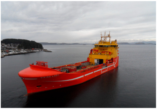
Figure 3.
Offshore engineering supply ship “Viking lady” [51]. For more detailed information about Viking Lady, please refer to Table S2 in the Supplementary Materials [40,41,51,52,53].
The Viking Lady uses molten carbonate fuel cells provided by MTU (Motoren-und Turbinen-Union Friedrichshafen GmbH, Friedrichshafen, Germany), with a power output of approximately 330 kW. Compared to traditional diesel power alone, the Viking Lady’s carbon dioxide emissions have been reduced by 20–30%, and nitrogen oxide emissions have decreased by up to 90%, demonstrating the feasibility of fuel cells in long-distance shipping. At the same time, the ship combines the low-emissions characteristics of LNG with the high efficiency of fuel cells, pioneering a new model for green shipping. Additionally, the ship employs a hybrid power system, equipped with four Wärtsilä 9L20DF (Wärtsilä, Helsinki, Finland) main diesel engines, each with a power output of 1700 kW, giving a total power output of 6800 kW. This allows the Viking Lady to switch flexibly between LNG and conventional fuels, providing a more efficient and cleaner energy option for long-distance voyages [51,52,53].
The Viking Lady is not only an advanced eco-friendly vessel but also an important symbol of the global shipping industry’s transition toward sustainable development, representing the green vision for the future of shipping.
- (3)
- Alsterwasser
Alsterwasser is a project initiated in 2006 by the Department of Urban Affairs and Environment of the Free and Hanseatic City of Hamburg, Germany, under the Zemships initiative. From 2007 to 2009, the design and integration of its fuel cell system and the construction of the corresponding hydrogen refueling stations were completed. The vessel officially began operations as an inland river tourist boat on the Alster River in 2008. Figure 4 shows the appearance and structure of “Alsterwasser”.

Figure 4.
(a) Alsterwasser appearance display [39]. (b) Schematic diagram of the system of Alsterwasser [54]. For more detailed information about Alsterwasser, please refer to Table S3 in the Supplementary Materials [39,54,55].
The Alsterwasser is the world’s first inland passenger vessel powered primarily by fuel cells. It has received widespread acclaim for its zero-emission and low-noise operation. The power comes from two PEMFCs, each with a power output of 48 kW, which generate electricity using hydrogen stored in high-pressure tanks, containing approximately 200 kg of hydrogen. The electric propulsion system then drives the propeller, and the only emissions during operation are water, completely avoiding the carbon emissions and pollutants associated with traditional diesel engines [39]. The Alsterwasser uses forced convection ventilation for its operation compartment, hydrogen storage compartment, and battery compartment. Specifically, the hydrogen storage compartment has a ventilation capacity greater than that of the operation and battery compartments to ensure the absolute safety of the hydrogen storage space.
Additionally, the Alsterwasser uses a hybrid power system that combines fuel cell technology with a lithium battery auxiliary system. The lithium-ion battery system stores excess electricity from the fuel cells, supporting the ship’s peak energy demands. This vessel has demonstrated the feasibility of hydrogen fuel cells in practical transportation applications, providing important references for the future design of green ships. However, the ship also faces challenges such as high construction and operational costs and insufficient hydrogen fuel infrastructure, limiting its large-scale adoption.
- (4)
- Elektra
Since 2016, a collaborative team led by Professor Gerd Holbach from the Technical University of Berlin has been working on the development of the world’s first hydrogen-powered tugboat, Elektra. The Elektra is a hybrid-powered, environmentally friendly vessel and is currently the world’s first tugboat to use a combination of fuel cells and battery power for propulsion. It is specifically designed for towing operations and cargo transportation in rivers and ports. Figure 5 shows the appearance and structure of “Elektra”.
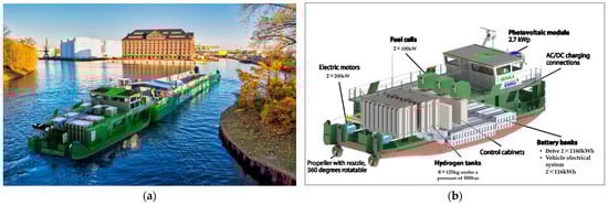
Figure 5.
(a) Elektra appearance display [56]. (b) Schematic diagram of the system of Elektra [57]. For more detailed information about Elektra, please refer to Table S4 in the Supplementary Materials [56,57,58].
In its design, Elektra combines the continuous power supply of fuel cells with the high-efficiency energy storage capabilities of lithium batteries. The newly developed hybrid power system includes 242 GO1050 modules, approved by classification societies, delivered by EST-Floattech, and 3 NT-PEMFC marine fuel cell systems. The vessel’s battery and fuel cell power systems are completely independent, working together to power the electric motor [58].
This not only achieves the goal of zero emissions but also improves efficiency and extends the vessel’s range through its hybrid power system. The Elektra represents the cutting edge of green shipping technology and provides an important reference and example for future environmentally friendly vessels in inland waterways.
- (5)
- Energy Observer
The “Energy Observer” was originally a racing boat used by a French sailing competition participant. After four modifications, it became the world’s first energy self-sufficient vessel powered by fuel cells. The ship is equipped with a PEMFC similar to the one used in Toyota’s hydrogen fuel cell vehicle “Mirai”, enabling it to reach speeds of 8 to 11 knots. In addition to hydrogen power, the vessel can also be powered by various renewable energy sources, such as solar, wind, and wave energy. The Energy Observer is equipped with Oceanwings, which have a wingspan of 12 m and an area of 31.5 m2. These wings are self-supporting and can rotate 360°. The ship’s solar panels have a total area of 141 m2, with a power output of 21 kW, and can automatically adjust their angle to optimize solar energy collection efficiency. Additionally, it is fitted with two 2 kW small vertical wind turbines and a hydro turbine, further ensuring a reliable energy supply for the Energy Observer [59,60]. Figure 6 shows the appearance and structure of “ Energy Observer”.
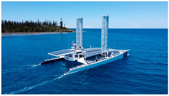
Figure 6.
Yacht “Energy Observer“ [59]. For more detailed information about Energy Observer, please refer to Table S5 in the Supplementary Materials [44,45,59,60].
The Energy Observer is a catamaran with a hybrid energy storage system: one group of lithium-ion batteries for short-term storage and eight hydrogen bottles for long-term storage. The main battery system, with a capacity of 112 kWh, supplies power to the electric motor through a 400 V shipboard grid, which is 2.5 times the capacity of the battery used in a Renault electric car. Another 18 kWh lithium-ion battery group powers the 24 V low-voltage network and daily ship systems, such as electronic navigation, onboard computers, and lighting [59,60].
As the world’s first vessel completely powered by renewable energy and hydrogen fuel, the Energy Observer is a landmark project in the clean energy field. It not only demonstrates the practical application of various renewable energy technologies in shipping but also, through its smart energy management system and electrolysis hydrogen production technology, has pioneered the achievement of total energy independence for ships.
- (6)
- Energy Observer Ⅱ
Energy Observer II is a new demonstration cargo ship developed by Victorien Erussard. In 2017, Erussard proved with the “Energy Observer” catamaran that ships could autonomously sail without relying on fossil fuels by utilizing advanced energy systems such as seawater desalination, hydrogen production, photovoltaic cells, and intelligent sails. He hopes to further demonstrate that cargo ships can also achieve this green navigation. Therefore, the Energy Observer has taken a new step by introducing the most representative ship design in the maritime transport industry: the Energy Observer II. Figure 7 shows the appearance and structure of “Energy Observer Ⅱ”.

Figure 7.
Cargo ship “Energy Observer Ⅱ” [61]. For more detailed information about Energy Observer Ⅱ, please refer to Table S6 in the Supplementary Materials [62,63,64,65].
This 120 m-long cargo ship is designed to achieve zero emissions, with a high level of autonomy and a large cargo capacity. Energy Observer II is equipped with a 2.5 MW PEMFC, capable of storing 70 tons of liquid hydrogen tank, or approximately 4000 m3. Additionally, Ayro, a company founded by Marc Van Peteghem, provided the ship with an advanced auxiliary propulsion system and equipped it with Oceanwings technology, marking the first time the company applied its system in actual operations.
The design of Energy Observer II focuses on replacing the current 5000-ton multipurpose cargo ships used for inland and coastal routes. As such, its onboard power system has been improved compared to Energy Observer, with fuel cells, lithium batteries, and wind power generation systems. The maximum electric propulsion power can reach 4 MW, providing strong support for the ship’s long-distance voyages. To ensure adaptability for the maritime sector, Energy Observer II uses liquid hydrogen as the ship’s fuel, which has a volume 4.3 times that of traditional marine diesel, making hydrogen storage a significant challenge. The launch of Energy Observer II marks an important step toward green and sustainable development in the shipping industry, showcasing the limitless possibilities of future maritime navigation.
- (7)
- Hydroville
Built in 2017, the Hydroville is the world’s first commercial passenger ferry equipped with a hydrogen fuel cell system. It was constructed by the Belgian company CMB and primarily operates on short routes between Belgium and the Netherlands. Figure 8 shows the appearance and structure of “Hydroville”.
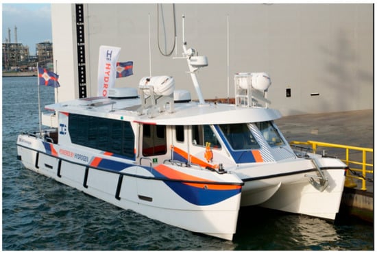
Figure 8.
Passenger ship “Hydroville“ [66]. For more detailed information about Hydroville, please refer to Table S7 in the Supplementary Materials [42,43,66,67].
The Hydroville features a hybrid power system, which includes two dual-fuel engines (H2ICED) with a total power of 441 kW and a 400 kWh battery pack, with a maximum speed of 27 knots. Under low-load conditions, the vessel can be powered solely by the battery, significantly reducing carbon emissions and noise levels. At full load, the diesel engines and battery system work together to provide higher power output. The use of this system allows the Hydroville to reduce fuel consumption by approximately 30% during operation, while cutting carbon dioxide emissions by more than 50% compared to traditional power systems [43,67].
Additionally, the Hydroville’s hull design incorporates hydrofoil technology, which uses the lift generated by the foils to partially lift the hull out of the water, reducing drag and improving speed and fuel efficiency. This design significantly enhances both the fuel efficiency and comfort of the vessel.
- (8)
- AIDAnova
The AIDAnova is an innovative cruise ship built by the German Meyer Werft shipyard (Papenburg, Germany) for AIDA Cruises. It incorporates several advanced technologies aimed at promoting green shipping. One of its key innovations is the use of fuel cells, particularly in its “Pa-X-ell2” research project. This project, which began in 2021, focuses on developing a fuel cell system powered by hydrogen derived from methanol. This technology not only offers the advantage of low emissions but also provides a more comfortable cruising experience by reducing noise and vibration. Figure 9 shows the appearance and structure of “AIDAnova”.
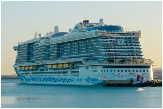
Figure 9.
Ocean liner “AIDAnova“ [43,68]. For more detailed information about AIDAnova, please refer to Table S8 in the Supplementary Materials [68,69,70].
AIDAnova, as the world’s first cruise ship to fully use low-emission LNG as fuel, has become one of the first ultra-large cruise ships to test fuel cell technology. The fuel cell system works by using methanol to generate hydrogen, which then powers the ship, providing clean energy for the propulsion system. Therefore, AIDAnova is equipped with three LNG storage tanks, with a total capacity of approximately 3570 m3. Compared to traditional LNG fuel, using fuel cells further reduces carbon dioxide emissions, and their operating life exceeds 35,000 h, which is longer than the battery life of conventional cars [69,70].
In addition, the AIDAnova is equipped with four Caterpillar MaK 16M46DF dual-fuel engines (Caterpillar, IL, USA), each with a power output of 15,440 kW, which, together with the fuel cell system, provide power for the entire ship. AIDA Cruises also plans to utilize more similar clean energy technologies in future shipping, including the use of green methanol produced from renewable energy, which will help reduce greenhouse gas emissions during the ship’s voyages.
- (9)
- MF Fannefjord
The MF Fannefjord, with its efficient operation and innovative green technologies, has become one of the most iconic ferries in Norway. Fjord1, one of Norway’s most important ferry operators, is committed to promoting green shipping, and many vessels in its fleet utilize electric or hybrid propulsion technologies. Figure 10 shows the appearance and structure of “MF Fannefjord”.
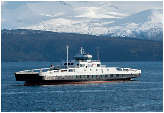
Figure 10.
Ferry “MF Fannefjord” [71]. For more detailed information about MF Fannefjord, please refer to Table S9 in the Supplementary Materials [71,72,73].
The MF Fannefjord is a ferry equipped with a hybrid propulsion system that combines liquefied natural gas, fuel cells, and lithium batteries. Originally a diesel–electric-powered LNG ferry, it was retrofitted with a 410 kWh battery energy storage system provided by Corvus Energy. The battery system consists of 63 AT6500 model lithium polymer (Corvus Energy, Bergen, Norway) batteries, which are capable of providing power based on different operational conditions, significantly improving energy efficiency and reducing emissions [71]. The battery stores energy during low power demand and helps balance high power demand, optimizing engine operation and reducing maintenance costs.
The MF Fannefjord is also equipped with a hydrogen storage system, consisting of two liquid hydrogen tanks, each capable of holding approximately 40 cubic meters of liquid hydrogen. The total hydrogen storage capacity is around 80 cubic meters, allowing the ferry to operate on hydrogen for about 2–3 daily trips [73].
Overall, the hybrid power system of the MF Fannefjord greatly enhances the vessel’s energy efficiency and environmental friendliness, representing an important practice in green shipping technology.
3.2.2. Fuel Cell Ships from 2019 to Present
- (1)
- Viking Energy
Viking Energy is a dual-fuel-powered ferry specifically designed for the Norwegian fjord region, created by Viking Ocean Cruises (Los Angeles, CA, the U.S.) and its partners. Since 2003, Viking Energy has been using LNG as its primary fuel and has become the world’s first platform supply vessel (PSV) powered by LNG. Figure 11 shows the appearance and structure of “Viking Energy”.

Figure 11.
Offshore engineering supply ship “Viking Energy“ [74]. For more detailed information about Viking Energy, please refer to Table S10 in the Supplementary Materials [75,76,77].
In 2024, the “Viking Energy” was converted to a dual-fuel propulsion system and tested with a Proton Exchange Membrane Fuel Cell module with a total power output of 2 MW, with an expected annual sailing time of up to 3000 h. Wärtsilä supplied four 6L32-DF engines (Wärtsilä, Helsinki, Finland), the complete fuel gas supply system, and the exhaust after-treatment system for the Viking Energy, while Prototech provided the fuel cell system, and Yara supplied ammonia fuel [77].
During the testing phase, the vessel will use ammonia to replace approximately two-thirds of the methane-based fuel, with the goal of meeting 60% to 70% of the energy consumption during the trials and demonstrating that the technology can meet 90% of the total power demand. The remaining energy required will be provided by LNG.
- (2)
- Sea Change
In July 2022, the American Maritime Company (Bremerton, WA, USA) and its owner, Switch Maritime, officially announced the launch of the world’s first commercially operated ship fully powered by hydrogen fuel cells, the Sea Change. The ship completed its first hydrogen fueling trial operation at the end of 2021. Once construction is completed, it will operate in the San Francisco Bay Area. Its development aims to demonstrate the feasibility of zero-emission hydrogen fuel cell propulsion technology for vessels. Figure 12 shows the appearance and structure of “Sea Change”.
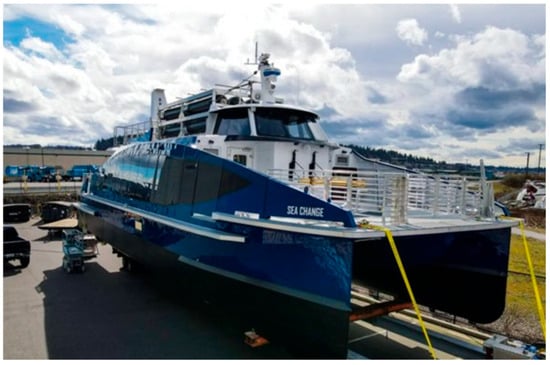
Figure 12.
Ferry “Sea Change” [78]. For more detailed information about Sea Change, please refer to Table S11 in the Supplementary Materials [79,80,81].
The Sea Change was designed and developed by ZEI Company (Oslo, Norway) and is equipped with an HD-120 PEM fuel cell system provided by Cummins (Columbus, IN, USA), with a total power output of approximately 3 × 120 kW. The ship also features 10 hexagonal Magnum high-pressure hydrogen storage tanks, capable of storing about 246 kg of compressed hydrogen at a pressure of 250 bar. This allows the ferry to operate for about 150 nautical miles at a cruising speed of approximately 12 knots and for roughly 16 h before refueling [80,81]. The Sea Change utilizes a hybrid power system, with a 100 kWh XALT lithium-ion battery that provides power to the vessel when the fuel cell response is slow.
The ferry can carry 75 passengers and features a catamaran design. Developed with $3 million in funding from the U.S. National Government, it was constructed by All American Marine shipyard. The Sea Change is expected to begin welcoming guests along the coastline around the end of spring 2023, marking an important step in the transformation of the U.S. maritime industry toward a sustainable future.
- (3)
- Chase Zero
Chase Zero is a typical zero-emission catamaran, whose advanced fuel cell power technology and sustainable design provide a model for future green maritime transportation. The vessel is fully powered by batteries, with advanced lithium-ion battery technology used as a supplement, achieving zero carbon emissions during operation. Chase Zero emits no greenhouse gases and also avoids the noise and water pollution generated by conventional ships during navigation, showcasing a high level of environmental friendliness. Figure 13 shows the appearance and structure of “Chase Zero”.
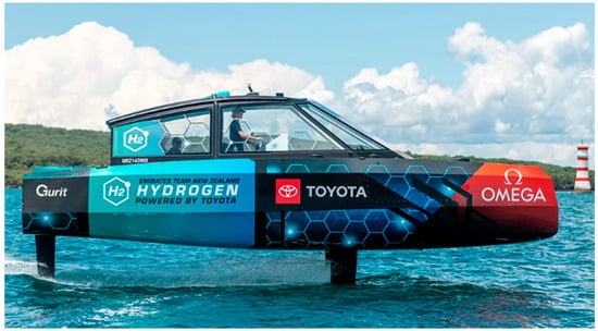
Figure 13.
Chase boat “Chase Zero“ [82]. For more detailed information about Chase Zero, please refer to Table S12 in the Supplementary Materials [83,84].
In terms of performance, the Chase Zero is equipped with two 80 kW Proton Exchange Membrane Fuel Cells provided by Toyota, which give it impressive range and high energy efficiency. These fuel cells were originally designed for the Mirai car, using a catalyst to combine the hydrogen stored in the vehicle with oxygen from the air, converting the hydrogen into 400 volts of direct current. The electricity generated by the fuel cells is stored in two 42 kWh batteries or directly fed to two 220 kW Emrax electric motors [84]. Additionally, the Chase Zero is equipped with four high-pressure carbon fiber tanks capable of storing hydrogen.
The successful operation of Chase Zero not only demonstrates the maturity and practicality of fully electric vessel technology but also provides the global shipping industry with a vision of a zero-emission future.
- (4)
- Suiso Frontier
The Suiso Frontier, designed and built by Kawasaki Heavy Industries of Japan (Kobe, Japan), is part of a hydrogen supply chain pilot project. The ship was launched in 2019, and in January 2021, Kawasaki Heavy Industries announced the completion of the LH2 (liquid hydrogen) terminal. As the world’s first liquid hydrogen carrier, Suiso Frontier represents a significant breakthrough in the hydrogen industry for maritime transport. By using hydrogen fuel cells and liquid hydrogen storage technology, the vessel not only provides a transportation solution for the future large-scale application of hydrogen energy but also lays the foundation for achieving low-carbon, sustainable shipping goals. Figure 14 shows the appearance and structure of “Suiso Frontier”.

Figure 14.
Transport ship “Suiso Frontier“ [85]. For more detailed information about Suiso Frontier, please refer to Table S13 in the Supplementary Materials [86,87,88].
The Suiso Frontier is equipped with a 1.5 MW PEM fuel cell (PEMFC) and features a 1250 m3 vacuum-insulated, double-layered liquefied hydrogen storage tank capable of carrying approximately 90 tons of liquid hydrogen. The design and construction of the vessel aim to offer a way to transport liquefied hydrogen, which is hydrogen gas cooled to −253 °C to become liquid hydrogen. Its volume is only 1/800th of its original gaseous volume, and it can transport liquid hydrogen without any cooling agents.
However, the Suiso Frontier also faces some challenges. First, hydrogen storage and transport technology are still in the relatively early stages, and the production and storage costs of liquid hydrogen are high, which may limit its widespread application. Secondly, the development of hydrogen infrastructure will take time, especially within the global shipping network.
Overall, the Suiso Frontier represents a major breakthrough in the shipping industry’s efforts to reduce carbon footprints and promote green energy, laying the foundation for a more environmentally friendly and efficient global shipping future [88].
- (5)
- Three Gorges Hydrogen Ship 1
Figure 15 shows Double-hulled transport vessel “Three Gorges Hydrogen Ship 1” and fuel cell for “Three Gorges Hydrogen Ship 1”.
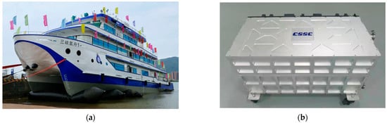
Figure 15.
(a) Double-hulled transport vessel “Three Gorges Hydrogen Ship 1“ (“三峡氢舟1” means “Three Gorges Hydrogen Ship 1”) [89]; (b) fuel cell for “Three Gorges Hydrogen Ship 1” [90]. For more detailed information about Three Gorges Hydrogen Ship 1, please refer to Table S14 in the Supplementary Materials [89,90,91,92].
On 17 March 2023, China’s first hydrogen fuel cell-powered working vessel, “Three Gorges Hydrogen Boat 1”, was officially launched, with classification by China Classification Society (CCS).
The “Three Gorges Hydrogen Boat 1” uses a hydrogen fuel cell and lithium battery power system. By refueling with 35 MPa compressed hydrogen, the hydrogen fuel cells convert the chemical energy of hydrogen and oxygen directly into electrical energy, providing power to the entire vessel and achieving zero pollution emissions throughout its operation. The vessel is equipped with one Proton Exchange Membrane Fuel Cell system and one lithium iron phosphate battery system with a power capacity of 1800 kWh as the main power source, connected to a DC grid. It has two fuel cell compartments, each containing four 70 kW RMZA-70K fuel cell modules. Additionally, the vessel adopts high-pressure hydrogen storage technology, capable of carrying approximately 250 kg of hydrogen, which provides about 4000 kWh of electrical energy [92].
The development of this vessel has propelled China’s hydrogen-powered shipping industry from a blank slate to the preliminary formation of a systematic standard. The implementation of this project will provide an important theoretical foundation and data support for the future promotion of hydrogen fuel cell vessels, as well as an important experimental platform for hydrogen fuel cell vessel testing and experiments in China.
- (6)
- HyDrOMer
In April 2022, HELION (Toulouse, France) and the French shipyard Piriou (Brittany region, France) signed a fuel cell contract to integrate the HELION fuel cell system into the “HyDrOMer”, a hydrogen hybrid dredger built by Piriou. HELION will supply the vessel with a 200 kW FC-RACK marine fuel cell, installed within a 15-foot container. This system is powered by compressed hydrogen stored in four 20-foot containers onboard (capable of carrying 200 kg of hydrogen). This setup supports the vessel’s operations while minimizing harmful emissions. Figure 16 shows the appearance and structure of “HyDrOMer”.
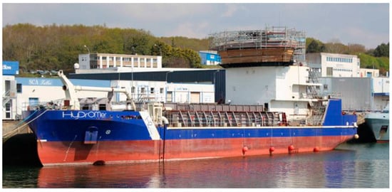
Figure 16.
Trailing suction dredger “HyDrOMer“ [93]. For more detailed information about HyDrOMer, please refer to Table S15 in the Supplementary Materials [47,94].
The HyDrOMer is the world’s first dredger operating with part of its installed power provided by hydrogen fuel cells. It generates electricity through the reaction of hydrogen and oxygen to drive electric motors, powering the vessel. Its marine power system also incorporates an energy storage system, a hydrogen storage system, and a range system, and is equipped with four Volvo Penta D16559kWe IMO Tier III generators (Volov Penta, Gothenburg, Sweden) and two 50 kWh lithium-ion batteries, providing a maximum total power of up to 1.5 MW. This allows it to operate efficiently while reducing fuel consumption and carbon dioxide emissions by an average of 20%.
The vessel is equipped with a dredging pump with a capacity of 6000 cubic meters per hour, installed at the bottom of the hull. The pump is connected to the dredging pipe for filling the hopper and to the bow coupling for beach replenishment through the “rainbow spraying” method. The dredging pump can fill the hopper to its maximum capacity in just 20 min [94].
Overall, the HyDrOMer vessel, with its advanced marine power system, not only enhances energy efficiency but also makes a positive contribution to environmental protection. It holds great potential for future applications and widespread promotion.
- (7)
- MF-Hydra
The MF Hydra was built in 2021, and its core power comes from two 200 kW FCwave fuel cell modules provided by Ballard, combined with a 1200 kWh lithium battery to form an efficient and environmentally friendly hybrid power system. The innovation of MF Hydra lies in its use of a liquid hydrogen storage solution. The ferry is equipped with an 80 cubic meter hydrogen storage tank, and the stored liquid hydrogen offers significant advantages over compressed hydrogen, including higher density, safer low-pressure storage, and lower transportation costs for long distances. This design will reduce MF Hydra’s annual carbon emissions by 95%. Figure 17 shows the appearance and structure of “MF-Hydra”.
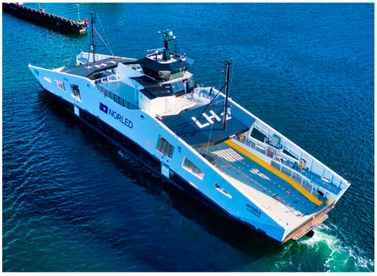
Figure 17.
Passenger ship “MF-Hydra“ [95]. For more detailed information about MF-Hydra, please refer to Table S16 in the Supplementary Materials [96,97,98].
In terms of propulsion, MF Hydra uses two electric motors driving fixed-pitch propellers, with two 440 kW generators providing power to the Schottel thrusters, enabling it to navigate steadily at a speed of 9 knots on the triangular route between Hjelmeland, Skipavik, and Nesvik [96,98].
The advanced fuel cell modules for MF Hydra were provided by Ballard (Burnaby, BC, Canada), while the hydrogen energy system was built by Germany’s Linde Engineering (Pullach, Germany). The system integration and installation were carried out by Norway’s Westcon (Haugesund, Norway) and SEAM (Dothan, AL, USA). After systematic dock testing and a two-week sea trial, MF Hydra officially received operational approval from the Norwegian Maritime Authority in March 2023. It is believed that MF Hydra will provide passengers with an unprecedented zero-emission sailing experience while also promoting the shipping industry towards a greener and more sustainable future.
- (8)
- Eastern Hydrogen Port
The “Dongfang Hydrogen Port” was built in 2024 and is China’s first container ship powered by hydrogen fuel cells. It can carry 64 standard containers at a time, with a maximum one-way voyage of 120 km. This marks a technological breakthrough for China in the field of hydrogen-powered vessels. Figure 18 shows the appearance and structure of “Eastern Hydrogen Port”.
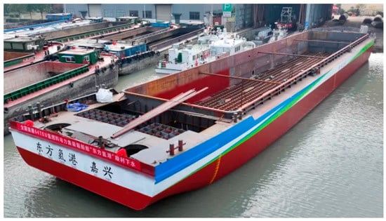
Figure 18.
Container ship “Eastern Hydrogen Port“ (“东方氢港” means “Eastern hydrogen port”) [99]. For more detailed information about Eastern Hydrogen Port, please refer to Table S17 in the Supplementary Materials [100,101].
In terms of design, the Dongfang Hydrogen Port is equipped with two 240 kW Honghan C240-PEM high-power hydrogen (Guohong Hydrogen Energy, Beijing, China) fuel cell units, combined with a traditional electric drive system. It is also equipped with two 220 kW individual motors as the main propulsion motors, ensuring stable operation in various navigation environments. The power system can automatically adjust the power output based on conditions such as speed and load, offering strong adaptability and intelligent management features.
Additionally, the hydrogen storage system has been precisely designed to store 550 kg of hydrogen, making it the largest hydrogen storage system currently used on a vessel. The power system of this ship effectively reduces noise and vibration, providing a quieter and more comfortable environment, making the Dongfang Hydrogen Port an important demonstration for the future of green shipping.
Through the observation of the above typical ship cases and the analysis of the data in Figure 19, it is clear that with continuous technological advancements, the power output of marine fuel cells is steadily increasing. The increase in battery power is not only reflected in the energy output of individual cells but also in improvements in system integration and management efficiency, particularly in the innovations in hydrogen storage and supply technologies. The ongoing expansion of the ship’s hydrogen storage capacity allows it to carry more hydrogen, thus meeting the demands for longer operational times and greater cruising distances. These advancements provide more possibilities for the shipping industry, enhancing both the economic efficiency of ships and contributing positively to environmental protection [102].
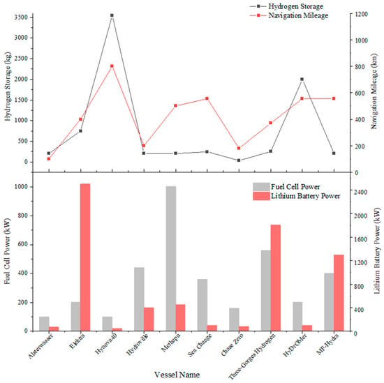
Figure 19.
Relationship among fuel cell power, lithium battery power, hydrogen storage, and navigation mileage.
Therefore, the gradual maturity of marine fuel cell and hydrogen storage technologies is not only making ship power systems more efficient and environmentally friendly but also paving the way for the global shipping industry to transition toward a path of low-carbon sustainable development.
4. Design and Optimization of Marine Fuel Cell Power Systems
4.1. Composition of Marine Fuel Cell Power Systems
The marine fuel cell power system is primarily used for the propulsion and power supply of ships. Its core components include the fuel cell system, hydrogen storage system, battery management system, power conversion system, and energy storage system. These systems work closely together, collaborating to form a complete solution for marine fuel cell power. This system can effectively improve the ship’s power efficiency, reduce pollution emissions, and enhance the ship’s range and reliability. Below is a detailed expansion of the main components:
- (1)
- Fuel Cell System
The fuel cell system is the core component of the ship’s fuel cell power system. It typically consists of the fuel cell stack, hydrogen/oxygen supply system, gas humidification system, hydrogen/oxygen recirculation system, cooling water circulation system, and load control system, among others. The system includes the following four main loops: the cathode air supply loop, anode hydrogen supply loop, cooling water circulation loop, and the electrical loop connected to the load. The principle of the fuel cell system is shown in Figure 20 [103,104].
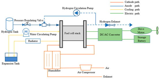
Figure 20.
Schematic diagram of fuel cell system [103,104].
In the anode hydrogen supply loop, hydrogen flows out from the high-pressure hydrogen tank, passes through a pressure-regulating proportional valve, and enters the fuel stack to participate in the electrochemical reaction. To improve economic efficiency, some systems additionally install a hydrogen circulation pump in the hydrogen supply loop, allowing excess hydrogen after the reaction to flow out through the anode flow path and mix with the incoming hydrogen. This not only improves the hydrogen utilization rate but also humidifies the anode hydrogen to a certain extent. To avoid nitrogen accumulation in the anode, a hydrogen exhaust system is usually added to the anode hydrogen loop, incorporating a hydrogen purge process. This involves periodically opening the exhaust valve at the hydrogen outlet to blow out accumulated nitrogen from the anode flow path, increasing the hydrogen concentration in the anode gas. This is the anode hydrogen supply loop.
In the cathode air supply loop, air is compressed by an air compressor to increase the gas pressure, then humidified to a certain degree before entering the fuel stack to participate in the reaction. The exhaust gas, carrying the water produced by the reaction, is then passed through the humidifier. After humidification, the air is released as exhaust [103].
The fuel cell cooling loop can be in the form of air cooling, water cooling, or insulated cooling, with water cooling being more common. Typically, the cooling loop includes a water tank, circulating water pump, and radiator, among other auxiliary equipment. The heat released during the fuel stack’s reaction process and the water vapor produced are cooled and recycled by the cooling water circulation system. By adjusting the cooling water flow, the temperature of the fuel stack can be controlled. The system also provides cooling water to the gas humidification system, maintaining the fuel system at a suitable temperature during operation and reducing the risk of damage to the fuel cell stack due to high temperatures caused by the heat generated in the reaction.
Finally, the fuel cell is connected to the load through the electrical loop, providing power to the load.
- (2)
- Hydrogen Storage System
The hydrogen storage system is a crucial component of the ship’s fuel cell power system, primarily responsible for storing and supplying the hydrogen required for the vessel. Hydrogen storage technologies can be classified into two types: physical-based hydrogen storage technology and material-based hydrogen storage technology.
Physical-based hydrogen storage technology refers to methods that alter the physical conditions of hydrogen storage to increase its density and enable storage. These technologies involve only physical transformation processes, with no hydrogen medium involved. They are cost-effective, easily release hydrogen, and achieve high concentration.
Material-based hydrogen storage, on the other hand, involves reactions between hydrogen and a hydrogen storage medium to form stable compounds, or it is achieved through adsorption. This category includes organic liquid hydrogen storage, metal hydride hydrogen storage, methanol hydrogen storage, and others [105].
Currently, ship-based hydrogen storage methods primarily include high-pressure gaseous hydrogen storage, cryogenic liquid hydrogen storage, and metal hydride hydrogen storage. When selecting a hydrogen storage method for fuel cell vessels, various factors must be considered, including safety, convenience, feasibility, and whether the hydrogen storage capacity is sufficient to meet the required cruising range. Table 2 presents the advantages and disadvantages of different hydrogen storage methods as well as application examples.
Table 2.
Comparison of hydrogen storage methods [106,107].
- (3)
- Battery Management System (BMS)
In the maritime field, BMS is the core component that coordinates the operation of fuel cells and other types of new energy sources for power supply. It is a key part of the hybrid power system. The BMS is used to control and manage the vessel’s electrical grid, and monitor and regulate the operation of the fuel cell system, energy storage batteries, and the distribution of electrical energy. It can monitor and coordinate the operation of the fuel cell and battery packs according to the real-time power demands.
Figure 21 shows the energy management strategy of hydrogen fuel cell. Fuel cells and lithium batteries are commonly used in energy management strategies for energy storage systems. These strategies are mainly divided into rule-based control strategies and optimization-based control strategies. Rule-based strategies are further divided into deterministic rules and fuzzy rules, while optimization-based strategies are classified into instantaneous optimization and global optimization.
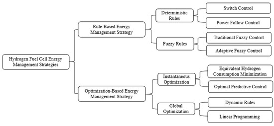
Figure 21.
Energy management strategy of hydrogen fuel cell.
Among them, deterministic rules include SOC switching control, power-following control, and state machine control.
SOC Switching Control: This strategy prioritizes lithium batteries as the main power source, with hydrogen fuel cells serving as an auxiliary power source. Theoretically, as long as the lithium battery’s State of Charge (SOC) is sufficiently high, it can handle most tasks. When the lithium battery’s SOC drops below a certain threshold, the hydrogen fuel cell charges the lithium battery at maximum power. When the SOC is between the minimum and maximum values, the hydrogen fuel cell charges the lithium battery at maximum efficiency. When the SOC exceeds a certain value, the hydrogen fuel cell stops charging.
Power-Following Control: This strategy uses the fuel cell as the primary power source. During the startup phase, the lithium battery helps to improve the startup efficiency. During the cruising phase, the hydrogen fuel cell operates at its maximum efficiency point, providing power and charging the lithium battery, while maintaining the lithium battery SOC within a narrow range around 80%. During acceleration, the hydrogen fuel cell continues to provide energy at its maximum efficiency point, and the lithium battery also provides energy. If there is extended deceleration, the lithium battery may reach a low SOC.
State Machine Control: Also known as the hydrogen fuel cell full-load control mode, this strategy combines both SOC switching control and power-following control. It takes into account the vehicle’s power demand, the lithium battery’s state, and the hydrogen fuel cell’s state, which are all complex and interrelated. Therefore, a more complex rule is required, such as a state machine, to differentiate between these conditions. For example, in power-following control, the power demand during acceleration is divided into two ranges: 51–70% and 71–100% power. When the demand is in the 51–70% range, the hydrogen fuel cell provides energy at its maximum efficiency point, and the lithium battery contributes the remaining energy. When the demand is in the 71–100% range, the hydrogen fuel cell provides maximum power output depending on the lithium battery’s state, and based on the lithium battery’s SOC, it is determined whether the lithium battery will provide energy or be charged [108].
In practical use, the interaction thresholds between marine fuel cells and energy storage batteries need to be dynamically adjusted based on the specific ship type, load characteristics, and safety redundancy. Typically, when the fuel cell and energy storage battery are at the SOC (State of Charge) boundaries, the charging trigger threshold is set at a battery SOC of ≤30–40%, at which point the fuel cell begins charging. The charging stop threshold is set at a battery SOC of ≥80–90%, at which point charging is halted. The emergency discharge threshold is set at a SOC of ≤20%, at which point non-critical load power supply is forcibly limited.
The power distribution thresholds for the ship’s fuel cell and energy storage batteries are as follows: the fuel cell’s baseline output power for the load is set to 40–60% of its rated value; the transient response threshold is when the load fluctuation exceeds ±10% of the rated power, and the energy storage battery compensates for this fluctuation; the peak power threshold is when the instantaneous output of the energy storage battery does not exceed 2–3 times its C-rate [109].
There are two mechanisms for dynamically adjusting these thresholds: the adaptive mechanism during navigation phases and the lifecycle degradation compensation. When the vessel is docked or cruising at low speed, the fuel cell output threshold is automatically lowered to 30% of the rated power, with the energy storage battery supplying power. When the vessel accelerates or operates at full load, the battery power compensation threshold is relaxed to ±15%, allowing for short-term over-limit operation. Additionally, when the fuel cell efficiency decreases by 5%, the SOC charging trigger threshold increases by 3–5%. When the energy storage battery capacity degrades to 80% of its State of Health (SOH), the peak power threshold is reduced by 0.5C [110,111,112].
The BMS also manages parameters such as hydrogen flow rate, battery voltage, and temperature, and performs fault diagnostics, optimizing operational efficiency to ensure the safety of the system. It ensures that energy from the fuel cell, energy storage batteries, and other energy sources is allocated efficiently, thus optimizing the fuel cell’s lifecycle and improving the system’s economic and operational efficiency. Figure 22 shows the workflow of the battery management system.

Figure 22.
Battery management system workflow diagram.
- (4)
- Power Conversion System (PCS)
The power conversion system (PCS) is primarily responsible for converting the direct current (DC) power generated by the fuel cell system into alternating current (AC) power required by the ship or directly supplying DC power to drive the motor that propels the vessel. This system includes components such as inverters, frequency converters, and transformers, which are used to monitor and adjust the voltage, current frequency, and power in real time to meet the changing power demands of the ship [113].
The ship’s power conversion system is a critical component of the ship’s electrical power system. It is responsible for converting and distributing energy between different power sources to ensure the vessel’s power supply, energy management, and the normal operation of electrical equipment.
- (5)
- Electric Motor and Drive System
The electric motor is a crucial component that converts electrical energy into mechanical energy to propel the ship forward. The performance of the electric motor directly impacts the ship’s power output, speed, and energy efficiency. The fuel cell and energy storage batteries provide the electrical power, while the electric motor drives the ship’s propeller to generate propulsion.
Currently, most fuel cell ships use Permanent Magnet Synchronous Motors (PMSMs) as the drive motor. Their high power density ensures the vessel can meet long-term propulsion demands [114]. Additionally, some small or special-purpose fuel cell vessels may use induction motors, especially in cost-sensitive applications or where efficiency is not the highest priority. However, due to their high efficiency and performance, Permanent Magnet Synchronous Motors have become the mainstream choice for fuel cell vessels.
Compared to traditional diesel engine propulsion, electric motor propulsion has lower emissions and noise, effectively reducing environmental pollution. The fuel cell system not only improves energy utilization efficiency but also provides smooth power output during the voyage. Overall, the combination of electric motor propulsion and the fuel cell system enhances the environmental friendliness of the vessel and reduces operational costs, making it a key direction for the future of green shipping.
- (6)
- Energy Storage System
During operations such as propulsion/reverse, maximum power acceleration, and stopping/steering, the ship’s load demand power can fluctuate significantly over short periods. The fuel cell’s output characteristics cannot fully meet the system’s power variation needs. Therefore, an energy storage system is required to improve the dynamic response capability of the power system, acting as a backup source while enhancing the durability of the fuel cell. The fuel cell system and energy storage system are connected via a DC/DC converter and the DC bus. Through corresponding energy management methods, their outputs are controlled to ensure the stable operation of the fuel cell hybrid power system.
Additionally, by controlling the hybrid power system’s output converter, the system can allocate power reasonably while maintaining stable bus voltage and enabling the automatic recovery of the energy storage system, thereby freeing the vessel from reliance on shore power.
The main types of shipboard energy storage equipment include flywheels, lithium batteries, and supercapacitors. The key characteristics of these devices are compared in Table 3 [115,116].
Table 3.
Comparison diagram of different energy storage devices [115,116].
As shown in Figure 23, lithium-ion batteries have developed rapidly in recent years, demonstrating significant advantages in the field of marine fuel cells. Fuel cell vessels can choose suitable lithium batteries as auxiliary energy sources based on actual operating conditions, making them an important technology for the shipping industry’s green transformation. In terms of environmental protection, lithium batteries can replace traditional diesel engine units, eliminating emissions such as sulfur oxides and particulate matter. When combined with fuel cells, photovoltaics, and wind power, they enable zero-carbon operation. In terms of performance, their energy density reaches 100–130 W/kg, enabling millisecond-level dynamic response capability. They can smooth out 40% of peak load, ensuring a quick response to the vessel’s load power while maintaining the ability to operate independently. Economically, the cycle life of lithium-ion batteries is continuously improving. High cycle efficiency and low maintenance requirements significantly optimize the entire lifecycle cost, accelerating the return on investment. With low-temperature self-heating technology, their capacity retention in −30 °C environments exceeds 85%, supporting applications in polar research vessels [117,118]. The application of lithium batteries in ferries, tugboats, research vessels, and other scenarios will continue to expand, helping to achieve the IMO energy efficiency targets.
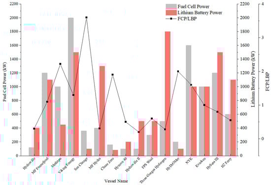
Figure 23.
Comparison of fuel cell power and lithium battery power of different ships [119,120,121,122].
4.2. Propulsion Mode of Marine Fuel Cell Power System
In practical applications, ships operating in marine environments often need to cope with fluctuating operating conditions. Fuel cells typically have a slow response time when dealing with changes in output power, which may not meet the instantaneous energy demands of electric motors, leading to issues where the fuel cell cannot provide power in time. To improve the stability and flexibility of the power supply system, an energy storage system is usually introduced to assist the fuel cell in providing power. The working modes of the fuel cell and energy storage system can be classified into the following three operating conditions [123,124]:
- When the output power of the fuel cell power generation system can meet the power requirements of the ship’s operating conditions, the fuel cell supplies power independently.
- When the fuel cell operates within its rated output power range and the output power exceeds the current demand, the surplus electrical energy can be distributed via the main generator’s distribution panel. Part of the electrical energy is supplied to the propulsion motor, while the remaining energy is stored by the energy storage system and simultaneously powers the ship’s electrical grid.
- In cases where the fuel cell’s output is insufficient to meet the operational demands, the system switches to a combined power supply mode with both the fuel cell and the energy storage system (or a parallel traditional diesel engine) to jointly meet the propulsion motor’s power needs.
Based on a detailed analysis of the ship’s performance under different operating conditions, four operating modes for the marine fuel cell power propulsion system can be summarized: hydrogen fuel cell independent power supply mode; fuel cell and energy storage device networking power supply mode; fuel cell and energy storage device dual-drive mode; and fuel cell, energy storage device, and diesel generator parallel power supply mode [124]. This power propulsion design, based on the collaborative operation of the fuel cell and energy storage system, can effectively handle complex conditions at sea, while enhancing energy efficiency and the overall performance of the ship. Figure 24 shows the structure diagram of marine PEMFC system.
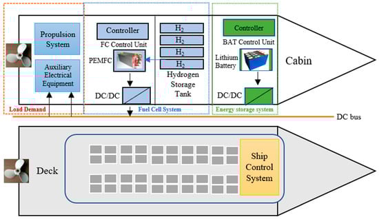
Figure 24.
Marine PEMFC system diagram [125].
- (1)
- Fuel Cell Independent Power Supply Mode
When the ship’s power demand is low, the hydrogen fuel cell can provide sufficient energy to meet the ship’s needs. At this point, the fuel cell can operate independently, powering the propulsion system and the ship’s electrical grid. The hydrogen fuel cell system is connected to the ship’s DC grid through a DC/DC converter, which transforms the fluctuating DC power generated by the fuel cell into stable DC power. This stable DC power is then converted into AC power by an inverter to drive the propulsion motor and supply power to the ship’s electrical load. Figure 25 is the schematic diagram of fuel cell single drive mode.
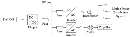
Figure 25.
Fuel cell single drive mode [126,127].
- (2)
- Fuel Cell Supplies Power to the Energy Storage Device and the Network Connection Mode
When the power and energy required for the ship’s navigation are small, and the output power of the fuel cell significantly exceeds the ship’s energy demand, the fuel cell can supply some of the electrical energy to the ship’s grid and use a bidirectional DC/DC converter to charge the energy storage device. The surplus electrical energy generated by the fuel cell is stored in the battery for use in the fuel cell and battery joint-drive mode or when the battery is used alone. Figure 26 is the schematic diagram of the mode of fuel cell supplying power to the energy storage device and networking at the same time.

Figure 26.
Fuel cell power supply mode for energy storage device and networking at the same time [126,128].
- (3)
- Fuel Cell and Energy Storage Device Dual-Drive Mode
When the ship experiences frequent load changes during navigation and the output energy of the fuel cell exceeds the ship’s needs, the fuel cell may not meet the transient energy demand of the electric motor due to its slower response speed. In this case, the system switches to a fuel cell and energy storage device joint-networking power supply mode to enhance the stability and flexibility of the power supply system. For example, lithium batteries, supercapacitors, and other energy storage devices can be combined to form the ship’s power system. The rapid response capability of the energy storage system compensates for the shortcomings of the fuel cell, and the dual power sources improve the system’s overall durability.
While the fuel cell outputs power, the energy storage device works in tandem to supply power to the motor, meeting the ship’s propulsion power and energy demands. When the fuel cell’s output exceeds the ship’s power needs and the energy storage device is not fully charged, the surplus power from the fuel cell can be stored in the energy storage device. This allows the electric ship to avoid using shore power and only requires quick hydrogen refueling to meet its operational needs within a given cycle. Figure 27 is the schematic diagram of dual-drive mode of fuel cell and energy storage device.
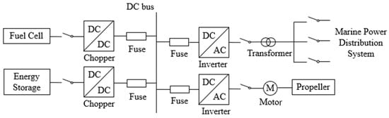
Figure 27.
Dual-drive mode of fuel cell and energy storage device [126,127].
- (4)
- Fuel Cell, Energy Storage Device, and Internal Combustion Engines in Parallel Power Supply
Although fuel cell technology is becoming more mature, current fuel cells still face some technical limitations, such as slow dynamic response speed and low output power of individual cells. To better meet the power requirements of vessels, internal combustion engines can be integrated into the vessel’s power system to achieve hybrid power propulsion. When the vessel requires a larger power and energy output, a parallel power supply system consisting of fuel cells, energy storage devices, and internal combustion engines can be employed. This system is managed and coordinated by an electrical station management system to ensure efficient collaboration among the various systems, thereby meeting the vessel’s power demand.
The auxiliary role of internal combustion engines in marine fuel cells mainly lies in providing additional power support and electricity supply for the fuel cells. In the vessel’s energy system, the internal combustion engine typically acts as part of the main propulsion system, working in coordination with the fuel cells. Fuel cells generate electricity through chemical reactions to meet the vessel’s primary power demand, while internal combustion engines provide additional power when necessary, especially during high load conditions or when the fuel cell cannot meet the instantaneous high power demand. Moreover, internal combustion engines can provide stable power supply to fuel cells, maintaining system stability when the fuel cell’s power output fluctuates. By combining these technologies, diesel engines and fuel cells can complement each other, improving the vessel’s energy efficiency and range, while reducing fuel consumption and emissions. Figure 28 is the schematic diagram of parallel power supply of fuel cell, energy storage device and internal combustion engine. Table 4 is a summary of current propulsion modes of fuel cell ship power system
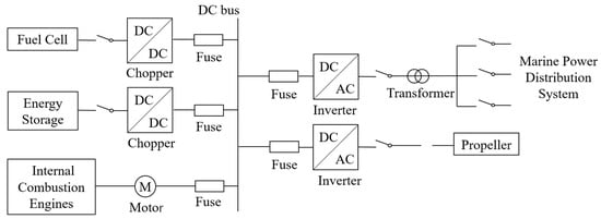
Figure 28.
Parallel power supply mode of fuel cell, energy storage device and diesel generator [126,128].
Table 4.
Current propulsion mode of fuel cell ship power system.
4.3. Optimization Method of Marine Fuel Cell Power System
Optimizing the marine fuel cell power system can not only improve the performance of fuel cells, reduce energy losses, extend range, and lower operating costs, but also significantly reduce carbon emissions and environmental pollution in the shipping industry. Additionally, optimizing the power system can enhance the reliability and safety of ships, preventing risks such as fuel leakage and pollution that are commonly associated with traditional power systems. Therefore, the optimization of the marine fuel cell power system is of great significance. This section primarily elaborates on the optimization of the power system in the following aspects:
- (1)
- Fuel Cell System:
The fuel cell stack is the core component of the system. Among them, the materials and manufacturing processes of the membrane electrode assembly (MEA) are critical to the performance of the fuel cell. The choice of materials and their processes (such as coating uniformity and inter-layer adhesion) directly determine the fuel cell’s power density, cost, and lifespan. By selecting corrosion-resistant and high-temperature-tolerant electrode materials, the long-term stability of the fuel cell can be improved. For example, replacing the Nafion membrane in PEMFCs with a more advanced polybenzimidazole proton exchange membrane allows the use of non-pure hydrogen and methanol as fuels, thereby expanding the range of fuel options [129].
Additionally, different flow field structures, dynamic/steady-state loading conditions, control strategies, and operating conditions all impact the stack’s performance. Flow field structures directly affect gas distribution and water management. Dynamic loading conditions influence the stack’s response speed and stability, while steady-state loading conditions determine its long-term operational stability and efficiency. Control strategies, such as precise control of current density, humidity, and temperature, affect stack performance and extend its lifespan [130]. Therefore, by adjusting relevant control conditions for the stack, the fuel cell’s power generation efficiency can be improved, further enhancing the overall performance of the marine fuel cell system.
- (2)
- Energy Storage System:
Increasing the energy density of the battery is an important goal in optimizing this power system. By developing batteries with higher energy density, more electrical energy can be stored within the same volume or weight, thereby increasing the ship’s range. Currently, lithium-ion batteries are the most commonly used battery technology in electric vessels, and researchers are actively exploring other novel batteries such as solid-state batteries, magnesium batteries, and sodium-ion batteries, which have theoretical energy densities far higher than traditional lithium batteries. Solid-state batteries, with their high energy density and safety, have become a key direction in the development of battery technology. If these technologies mature and are commercialized, they will greatly promote the development of electric vessels [131].
- (3)
- Multi-Stage Hybrid Power Systems:
Due to the current slow response of fuel cell technology and its incomplete maturity, it may not provide sufficient power immediately during load changes or rapid starts, which limits its application in some high-dynamic-demand scenarios. To improve the overall efficiency and power output of the system, integrating the fuel cell system with diesel–electric propulsion systems or other energy sources to form a hybrid power system is a viable solution. Depending on the navigation state, the optimal power source can be selected: fuel cells are mainly used at low loads, while internal combustion engines can serve as auxiliary power sources at high loads or in special situations. By optimizing energy management strategies, the output efficiency of fuel cells can be improved, overall fuel consumption reduced, and the vessel’s range extended.
For example, the “Heyue” cruise ship uses a “power battery + fuel oil + solar photovoltaic” hybrid power system, which enables the concept of “where there is light, there is power, and where there is power, there is storage.” This effectively solves the range anxiety of purely electric vessels. The Norwegian “Viking Lady” uses a traditional diesel–electric propulsion system alongside fuel cell technology [51,132].
- (4)
- Use of Intelligent Energy Management Systems (EMSs):
By installing advanced sensors and monitoring systems on the vessel, the intelligent energy management system (EMS) can collect real-time data on the ship’s speed, load, current/voltage, and more. It can monitor and regulate the distribution of various energy sources on board, dynamically adjusting energy distribution based on the vessel’s operational state. This optimizes the load distribution between the fuel cell and other power sources, ensuring that the fuel cell system operates under optimal conditions and maximizes the fuel cell’s efficiency.
5. Application Analysis of Marine Fuel Cell in the Same Scenario
This section compares and analyzes the application of marine fuel cells with those used in other scenarios (automotive and aviation applications). Comparing the automotive, aviation, and other fields can reveal differences in size and structural design, manufacturing processes, and power requirements of fuel cell technology in different contexts, helping the industry optimize design and application. Additionally, a cost–benefit analysis of marine fuel cells compared to fuel cells in other sectors is conducted to assess the economic viability and market potential of the technology. Cross-sector comparison and analysis will allow a deeper understanding of the advantages and challenges of marine fuel cells, promoting their widespread application in the shipping industry and other sectors.
5.1. Application Analysis of Marine Fuel Cells and Automotive Fuel Cells
Fuel Cell Electric Vehicles (FCEVs) are a type of new energy vehicle that uses hydrogen as fuel, generating electrical energy through the electrochemical reaction in a hydrogen fuel cell to drive an electric motor. These vehicles not only achieve zero emissions but also offer high energy efficiency and long driving range.
In 1966, the world’s first hydrogen fuel cell vehicle Electrovan was designed by General Motors in the United States, capable of providing a stable power output of 32 kW, marking the beginning of the development of hydrogen fuel cell vehicles [133]. In the early 21st century, Japan and South Korea took over the research and development leadership in hydrogen fuel cell vehicles. Toyota and Honda, respectively, launched prototype fuel cell vehicles, signifying further maturity of fuel cell technology. Many car manufacturers also started to enter this field for research and development. In 2014, Toyota officially launched the world’s first mass-produced fuel cell vehicle, the Toyota Mirai [134]. That same year, Hyundai also introduced its fuel cell vehicle, the Hyundai ix35 Fuel Cell (Hyundai Motor Company, Seoul, Republic of Korea), which was sold in some markets [135]. By the 2020s, fuel cell technology gradually found new applications in commercial vehicles, buses, trucks, and other fields. Table 5 describes the application of marine/vehicle fuel cells.
Table 5.
Application instructions for ship/vehicle fuel cells [136].
Therefore, this section will analyze the differences between marine fuel cells and vehicle fuel cells from the following four aspects, providing guidance for the development of marine fuel cells.
- (1)
- Differences in Working Principles and Power Systems
The working principle of fuel cell vehicles is as follows: Hydrogen (H2) from the high-pressure hydrogen storage tank is transported to the fuel cell stack through the hydrogen supply system, where it undergoes an electrochemical reaction with oxygen (O2) delivered by the air compressor, generating water and electrical energy. The generated electricity is sent to the motor controller, where it is converted into alternating current to drive the electric motor. Under the influence of three-phase alternating current, the motor generates torque and a certain speed, which is reduced and amplified by the reduction mechanism, driving the vehicle. Along with the auxiliary power source, complementary power supply is achieved. A fuel cell vehicle is more like an extended-range vehicle, meaning it is an electric vehicle with the addition of a fuel cell as the main power source. By adopting the “fuel cell and energy storage device dual-drive mode” described earlier, the vehicle’s driving range is extended, alleviating the range anxiety of pure electric vehicles [137,138]. Figure 29 shows the principle and structure of vehicle fuel cell.
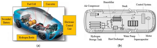
Figure 29.
(a) Layout of fuel cell vehicle power system onboard [139]; (b) structural diagram of hydrogen fuel cell vehicle [139].
The structure of the fuel cell power system for vehicles is shown in the diagram and mainly consists of the fuel cell, lithium battery, main inverter, auxiliary inverter, and other components. The fuel cell and the power lithium battery together provide energy to the main and auxiliary inverters. The main inverter converts the electrical energy in the intermediate DC bus into three-phase AC power, which is supplied to the traction motor, while the auxiliary inverter powers devices such as the compressor and water pump. The fuel cell serves as the primary power source for the entire vehicle, while the lithium battery has a fast charge/discharge response. When the vehicle’s energy demand changes significantly, the power lithium battery quickly releases or absorbs energy.
During the vehicle’s braking process, the traction motor becomes a generator, and the lithium battery stores the energy recovered from braking. The total traction power is the sum of the main and auxiliary inverter powers. When the vehicle’s traction power exceeds the fuel cell power, the lithium battery provides power support as an auxiliary DC source. When the traction power is less than the fuel cell power, the lithium battery absorbs the excess power as a DC load. In cases where the operating conditions change and rapid power adjustment is needed, the power lithium battery responds quickly until the fuel cell output power is fully adjusted [140]. Figure 30 shows the topological structure of vehicle fuel cell.
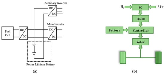
Figure 30.
(a) Working principle diagram of automotive fuel cell [139]; (b) topology structure diagram of automotive fuel cell [141].
Based on the propulsion methods described in Chapter 4 for marine fuel cell power systems, it can be observed that there are significant similarities between the driving modes of both systems. The only difference is that, at present, marine fuel cells do not have a power recovery system during the braking phase, meaning the remaining power cannot be fed back into the energy storage device.
In automotive fuel cells, a braking energy recovery system has already been applied. This system converts excess kinetic energy into electrical energy during braking and feeds it back into the energy storage device (such as lithium batteries or supercapacitors), thereby improving energy efficiency and extending the driving range. However, in marine fuel cell power systems, due to technical limitations or design considerations, a similar energy recovery mechanism is not yet commonly implemented. This means that when a vessel slows down or brakes, the remaining power is not effectively converted and stored, but instead wasted in the form of heat or other forms.
This absence leads to suboptimal energy use efficiency in marine fuel cell systems, especially in frequent stop-and-go sailing environments. The unrecaptured energy will further increase fuel consumption and impact overall economic and environmental performance. Therefore, in future designs of marine fuel cell systems, incorporating energy recovery technologies similar to those in electric vehicles will be an important direction for improving system efficiency and reducing energy consumption.
- (2)
- Differences in application environments.
Marine Fuel Cells: Ships typically operate in open waters and face harsh weather conditions such as winds, waves, salt mist, and seawater corrosion. During navigation, ships are prone to rocking and vibrations, with the presence of humid water vapor and salt-laden air. These conditions can cause damage to the fuel cell system’s pipelines, leading to damage to the fuel stack, and even hydrogen leakage and explosion accidents. Therefore, marine fuel cells must have strong anti-interference capabilities and be able to operate stably over long periods, providing sufficient power to support long-distance voyages [142].
Automotive Fuel Cells: Automotive fuel cells have lower environmental requirements and operate in relatively stable conditions. They are mainly used for urban transportation and short- to medium-distance daily driving. Unlike marine environments, they do not need to deal with seawater, salt mist, or other special conditions but require fast hydrogen refueling and a higher driving range [143]. Table 6 is the environmental adaptability test items of marine/vehicle fuel cells.
Table 6.
Table of environmental adaptability test items [144].
Based on the contents of the above table, it can be observed that the application environment requirements for marine fuel cells are more stringent compared to those for automotive fuel cells, and more environmental adaptability projects are involved. Marine fuel cells need to operate in special marine environments, which often pose higher challenges and variability.
- (3)
- Hydrogen Storage and Refueling
Marine Fuel Cells: Fuel cell vessels face significant challenges such as long routes and the scarcity of hydrogen refueling ports, which impose notable limitations on their range. Therefore, selecting the appropriate hydrogen storage method is particularly important for these vessels. Table 7 provides a more precise classification of hydrogen storage methods based on vessel types, with the storage methods for ships being more complex than those for vehicles.
Table 7.
Table of hydrogen storage methods for ships.
Marine hydrogen storage systems have the characteristics of lower weight requirements and higher volume requirements. Therefore, at this stage, high-pressure hydrogen storage and metal hydride hydrogen storage technologies are becoming increasingly widespread in ships. These storage methods effectively meet the unique hydrogen storage demands of vessels, providing sufficient hydrogen storage capacity while ensuring that the ship can maintain a long range during operation.
Currently, the feasible hydrogen refueling modes for waterborne applications can be broadly categorized into the following five types:
- Shore-to-ship refueling;
- Hydrogen trailer refueling;
- Barge-to-ship refueling;
- Ship-to-ship refueling;
- Replacement of hydrogen fuel tanks.
Regarding hydrogen refueling infrastructure for marine applications, the necessary facilities are not yet widespread, and the investment costs for building hydrogen transportation pipelines are high. Additionally, specialized vessels designed for hydrogen transportation require further research and development. Both the construction costs and hydrogen transportation costs are higher than those for land-based automotive hydrogen applications [145].
Automotive Fuel Cells: Fuel cell vehicles are smaller in size and have a shorter range, with relatively convenient land-based hydrogen refueling infrastructure. Therefore, the current high-pressure hydrogen storage method meets the requirements for automotive hydrogen energy. The construction of land-based hydrogen refueling stations is progressing steadily, and a certain scale has already been achieved [146].
- (4)
- Power Demand Differences
Marine Fuel Cells: Due to the large size of ships and their requirement for long-range capabilities, marine fuel cell systems must have higher power density and greater energy conversion efficiency to support high-load operations. The required power is typically above 100 kW, with multiple fuel cell systems connected in parallel to provide stable long-term power output. Marine fuel cell systems often integrate other energy sources like wind power, solar power, and diesel, making the power system hybrid (fuel cell + diesel engine + battery) to allow switching energy sources as needed, ensuring stability and range during the voyage.
Automotive Fuel Cells: The power demand for automotive fuel cells is relatively low, typically around 100 kW, but with greater fluctuations in output power. This requires rapid response capabilities, high energy conversion efficiency, and a longer driving range to meet the high-frequency travel demands of urban transportation. In addition to meeting the driving needs, automotive fuel cells must also consider quick acceleration and smooth startup, usually paired with a battery pack to provide necessary short-term power output and fast response capabilities [147].
Currently, the technical standards and engineering practices for hydrogen fuel cell vehicles have been largely refined and established at an initial scale. When applying these technologies to ships, some of the lessons learned from automotive applications can be leveraged. However, it is crucial to recognize that the operational conditions for marine vessels differ significantly from those of automotive environments, each presenting unique characteristics. Numerous technical challenges remain to be addressed and overcome.
5.2. Comparison of Marine Fuel Cell and Aviation Fuel Cell Applications
In recent years, hydrogen energy, widely regarded as “the ultimate energy source of the 21st century”, has received significant attention. Many top-level strategic plans related to hydrogen energy in aviation have been issued: the European Union released the “Hydrogen Aviation” research report, the United Kingdom released the “National Hydrogen Strategy,” and the United States released the “Hydrogen Program Development Plan.” Countries have been increasing investments in technologies such as hydrogen turbine engines and hydrogen fuel cells, aiming to secure a leading position in the hydrogen aviation sector [148,149,150,151].
Aviation fuel cells refer to fuel cell systems used in the aviation field to provide power to aircraft. Compared to traditional aviation gas turbine engines or piston engines, fuel cells, as a clean and efficient power source, have potential advantages in terms of environmental protection and fuel utilization efficiency.
Fuel cell systems are significantly different from traditional gas turbine systems in terms of structure. When using fuel cells as the power system for aircraft, almost all aircraft components need to be completely redesigned. One of the major changes involves fuel delivery and storage. Currently, aircraft using hydrogen fuel cells generally require large amounts of hydrogen storage containers, which increases the fuel storage space within the fuselage, thus enlarging the overall size of the aircraft. This is a key limitation for aviation fuel cells. Figure 31 shows the flow chart of aviation fuel cell power generation.

Figure 31.
Aviation fuel cell electric fan engine [152].
However, aviation fuel cells have also made certain progress. In 2016, H2FLY successfully conducted 32 flight tests over 4 days with its developed HY4 aircraft, verifying the scalability of H2FLY’s fuel cell power system and demonstrating its fast refueling capability. In December 2021, the U.K. Aerospace Technology Institute released the Fly-Zero concept for a liquid hydrogen-powered long-range medium-sized aircraft and published the detailed design in early 2022. The Fly-Zero aircraft is equipped with two hydrogen fuel turbofan engines, with fuel stored in a pair of cryogenic liquid hydrogen tanks in the rear fuselage and two smaller liquid hydrogen tanks located on both sides of the front fuselage [153,154]. Figure 32 shows the first flight of H2FLY aircraft.
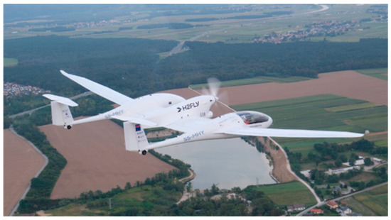
Figure 32.
H2FLY achieves maiden flight with liquid hydrogen-powered electric aircraft [155].
This section will analyze the differences between marine fuel cells and aviation fuel cells from four aspects, providing guidance for the development of marine fuel cells.
- (1)
- Application Environment Differences
Table 8 shows the application differences between marine fuel cells and aviation fuel cells under different environments.
Table 8.
Comparison table of environmental differences [156].
- (2)
- Fuel Selection
Table 9 shows the differences in fuel selection between marine fuel cells and aviation fuel cells.
Table 9.
Comparison table of fuel selection [157].
- (3)
- Power Requirements
Table 10 shows the differences in power requirements between marine fuel cells and aviation fuel cells.
Table 10.
Comparison table of power requirements [158].
- (4)
- System Design
Table 11 shows the differences in system design between marine fuel cells and aviation fuel cells.
Table 11.
Comparison table of system design [159].
Figure 33 shows the diagram of fuel cell hybrid propulsion system for aviation.
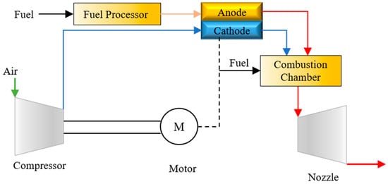
Figure 33.
Diagram of fuel cell hybrid propulsion system for aviation [160].
Current aviation power technologies and research equipment need further improvement. The existing structure of aviation engines is not suitable for hydrogen combustion. When hydrogen fuel burns, it reacts rapidly with oxygen, producing higher combustion temperatures and faster flame propagation. This leads to the formation of excessive nitrogen oxides and makes the occurrence of backfire more likely, preventing the current structure of aviation engine combustion chambers from achieving stable hydrogen combustion. Similarly to marine fuel cells, hydrogen energy, as a clean and efficient new energy source, has not yet been officially deployed in either sector. The challenges faced in the application of hydrogen fuel involve not only the technical problems of power systems but also aspects related to hydrogen production, storage, and transportation.
5.3. Comparison of Marine Fuel Cell and Locomotive Fuel Cell Applications
As hydrogen energy is increasingly emphasized by various countries, and hydrogen fuel cells are gradually being used in the transportation sector, the power drive systems for locomotives are also changing. In recent years, manufacturers have paid more attention to fuel cell technology and increased their investment in the research and development of fuel cell locomotives.
The traditional power source for locomotives is mainly derived from the electric grid or thermal engines. However, the power system for locomotives has already been electrified, meaning that different forms of energy are converted into electricity, which then drives the traction motors. This still causes significant air pollution.
Unlike traditional diesel locomotives, fuel cell locomotives use fuel cells as their power source. The electricity generated from the fuel cells is used for traction, and no direct pollutants are emitted, making the operation clean, environmentally friendly, and efficient. This makes fuel cell locomotives an inevitable choice for future mainline railways.
Since the 21st century, research on the application of hydrogen energy in rail vehicles has been increasing both domestically and internationally. In 2002, the U.S. developed the world’s first fuel cell locomotive with a power of 17 kW. In 2006, East Japan Railway Company (Tokyo, Japan) developed the world’s first fuel cell hybrid locomotive, which used two 95 kW induction motors as traction motors, two 65 kW fuel cells as the main power source, and a 19 kWh lithium battery as an auxiliary power source. In 2007, the Burlington Northern Santa Fe Railway Company (BNSF) (Fort Worth, TX, USA) in the U.S. worked with a vehicle project company based in Colorado to develop the world’s first hydrogen energy hybrid locomotive, which was equipped with two sets of Proton Exchange Membrane Fuel Cells with a total power of 250 kW, and a set of lead-acid batteries with an instantaneous power of over 1 MW. Additionally, Alstom in France developed the Coradia iLint, the world’s first commercially available hydrogen fuel cell passenger train. The University of Birmingham in the U.K. successfully developed the HydroFLEX hydrogen-powered train, and Canadian Pacific Railway (Calgary, AB, Canada) developed the H20EL hydrogen-powered freight locomotive, which was planned to be put into operation in 2022 [161,162,163]. Figure 34 shows the hydrogen-powered passenger train Coradia iLint.
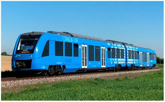
Figure 34.
Hydrogen-powered passenger train Coradia iLint [164].
Compared to other countries, China’s research on fuel cells in the rail transportation sector is still in its early stages. China’s first fuel cell locomotive, “Lantian,” was successfully developed by Southwest Jiaotong University in January 2013. This locomotive uses a 150 kW fuel cell as the traction power source and two 120 kW Permanent Magnet Synchronous Motors as traction motors. The fuel cell locomotive is shown in Figure 35.
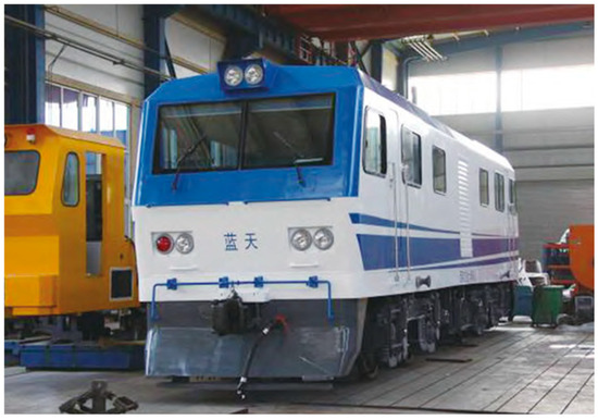
Figure 35.
“The Blue sky” fuel cell locomotive (“蓝天” means “The Blue Sky locomotive”) [162].
In 2020, China State Railway Group Co., Ltd. (Beijing, China) released the “Outline of the Railway Pioneer Plan for Building a Transportation Power in the New Era”, which proposed “improving the locomotive product spectrum and developing the next generation of electric, diesel, hybrid, new energy, and multi-source locomotives.” In 2021, the National Railway Administration (Beijing, China) issued the “14th Five-Year Plan for Railway Science and Technology Innovation”, which emphasized “promoting the development of hybrid and low-carbon power sources.” The development and application of hybrid locomotives received significant attention. In January 2021, CRRC Datong Company (Datong, China) launched the fuel cell locomotive “Lantian”, which uses a “hydrogen fuel cell + lithium titanate battery” hybrid power system with a total vehicle power of 700 kW. In September 2022, CRRC Zhuzhou Electric Locomotive Co., Ltd. (Zhuzhou, China) began trial operation of a hydrogen energy hybrid shunting locomotive, equipped with a 400 kW hydrogen fuel cell system, achieving a total vehicle power of 2400 kW. This is currently the largest hydrogen fuel cell system and the highest total vehicle power of China’s hydrogen energy rail transportation vehicles, with the largest onboard hydrogen storage capacity. In 2024, the first Chinese hydrogen energy intelligent intercity train set, CINOVA H2, independently developed by CRRC Qingdao Sifang Locomotive and Rolling Stock Co., Ltd. (Qingdao, China), was officially unveiled at the International Railway Technology Exhibition in Berlin, Germany. The development and application of fuel cell locomotives have provided strong support for China’s railway transportation to utilize clean energy and implement the “dual carbon” strategy.
The main structure of a fuel cell locomotive can be divided into two major parts: mechanical and electrical. The mechanical part mainly consists of the body, traction device, bogie, and braking system. The electrical system includes the fuel cell, traction inverter, traction motor, locomotive control system, and auxiliary systems, among others. Figure 36 shows the structural schematic diagram of the fuel cell locomotive.

Figure 36.
The structural schematic diagram of the fuel cell locomotive [163].
Currently, fuel cell locomotives convert chemical energy directly into electrical energy through the fuel cell stack. However, they are easily influenced by the hydrogen fuel gas concentration, flow rate, and reaction time, leading to issues such as soft output characteristics, slow dynamic response, and the inability to achieve energy recovery. Power batteries, such as lithium batteries, have higher power density and efficient energy recovery advantages. Therefore, the rail transit industry widely adopts a “hydrogen fuel cell + power battery” hybrid power system, where the advantages of both are complementary. Hybrid locomotives can achieve both high power density and high energy density, fully utilizing the strengths of each power source. Figure 37 shows the structural schematic diagram of the fuel cell and battery hybrid locomotive.
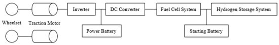
Figure 37.
The structural schematic diagram of the fuel cell and battery hybrid locomotive [163].
The section analyzes the differences between marine fuel cells and locomotive fuel cells from the following three aspects to provide guidance for the development of marine fuel cells:
- (1)
- Application Environment and Power Requirements
Marine Fuel Cells: Ships primarily operate in the ocean, facing the impact of marine conditions such as waves, wind, and tides. They need to have high stability and durability to cope with complex maritime conditions.
Locomotive Fuel Cells: Locomotives are similar to vehicles, as they typically cover much greater daily distances than cars and face a variety of terrains and station stops. Therefore, the power requirements of locomotives are often focused on frequent starts and stops as well as high-load operation. Accordingly, locomotive fuel cells place more emphasis on rapid response and high power density. This enables them to adapt to changing terrains and shorter refueling/recharging times, which is something that marine fuel cells can learn from locomotives.
- (2)
- Technical Adaptability
Marine Fuel Cells: Marine fuel cells face greater technical challenges, particularly in terms of voyage range and the stability of the power system. Key technical difficulties include efficient hydrogen storage and refueling, corrosion-resistant design, and the long-term stable operation of ships in harsh marine environments.
Locomotive Fuel Cells: In high-frequency operations, the durability and efficiency of fuel cells are crucial, especially in high-speed rail or urban rail transit systems. The main technical challenges for locomotive fuel cells focus on achieving high power density and rapid response capability. Fuel cells must maintain efficient and stable performance under varying conditions. Additionally, high manufacturing and operational costs, as well as relatively short service life, present obstacles to the widespread adoption of fuel cell-powered locomotives. The wide and rapid fluctuations in locomotive loads significantly impact fuel cell longevity. Moreover, regenerative braking systems are required to recover braking energy.
- (3)
- Hydrogen Storage and Refueling Methods
Marine Fuel Cells: Hydrogen on ships is typically stored in either liquid or high-pressure gas form. It is essential to ensure the safe and efficient supply of hydrogen during long voyages at sea. Additionally, the hydrogen storage system must take into account factors such as the available space, weight, and safety on the ship.
Locomotive Fuel Cells: For locomotives, hydrogen is mainly stored in high-pressure gas form. Dedicated hydrogen refueling stations are built at different locations, making it relatively convenient for locomotives to refuel with hydrogen.
This section compares locomotive fuel cells with marine fuel cells, mainly because locomotives have more similarities with marine transportation, including long-distance coverage, large cargo capacity, relatively low average speeds (for freight trains), and fewer restrictions on the mass of the drive system. Moreover, in a country like China with an extensive railway network, this comparison becomes even more relevant. Therefore, the analysis of locomotive fuel cells is particularly important.
6. Existing Problems of Marine Fuel Cell Technology
In recent years, the hydrogen energy industry has been strongly promoted by many countries around the world. Significant progress has been made in hydrogen fuel cell technology, green hydrogen production technology, and hydrogen fuel storage and refueling technologies. However, the following issues still persist with the application of fuel cells in ship power propulsion systems:
- (1)
- Immaturity of Marine Fuel Cell Technology:
In the operation of fuel cell systems, uneven distribution of substances is a key factor leading to the decline in fuel cell performance, efficiency, and durability. Many transport processes occur simultaneously within the fuel cell, such as the supply of reactant gases, discharge of byproducts, and charge transfer, all of which negatively impact the fuel cell’s performance and health. Currently, fuel cell modules and fuel cell power systems are primarily used in automotive applications, whereas there are significant differences between the working environment and operational requirements of ships and vehicles.
Current fuel cell power outputs generally do not exceed 350 kW, and their lifespan typically does not exceed 20,000 h. However, meeting the energy demands of ships requires a large number of individual cells, which is significantly different from the performance of marine diesel engines. Given the limited space aboard ships, the integration of large-power, long-lifetime hydrogen fuel cell systems for marine applications still requires breakthroughs. There is an urgent need for research into marine fuel cell systems to advance the engineering applications of hydrogen-powered ships [165].
In China, research on marine fuel cells is mainly conducted at universities and certain research institutes, focusing primarily on Proton Exchange Membrane Fuel Cells. However, research on key fuel cell components such as bipolar plates, membrane electrodes, and catalysts is still in the experimental stage, with little focus on engineering applications.
- (2)
- Hydrogen Production, Storage, and Refueling Issues Yet to be Solved:
The production, storage, and refueling of hydrogen for marine use are major bottlenecks restricting the development of fuel cells.
Hydrogen Production: Hydrogen production technology mainly relies on coal-based methods, with numerous challenges to green hydrogen production. The key materials and components involved in electrolysis for hydrogen production are prohibitively expensive, resulting in high production costs. While hydrogen production from renewable sources such as solar, wind, and biomass energy is technically feasible, it lacks economic competitiveness when compared to coal-based hydrogen production, due to low energy density, poor stability, and the need for further improvements in hydrogen production efficiency.
Hydrogen Storage: Hydrogen can be stored in gaseous, liquid, or solid forms. To meet the needs of ships, a balance must be found between hydrogen storage density, safety, and cost, and high-performance storage technologies suitable for ships must be developed. Although hydrogen has the highest mass energy density of any fuel, its volumetric energy density is extremely low. For example, the volumetric energy density of 35 MPa compressed hydrogen is only about 10% of the volumetric energy density of diesel [166]. Therefore, when fuel cells replace diesel engines as the power source, the volume of high-pressure gas bottles required for hydrogen storage will be much larger than the current fuel storage tanks for diesel. Additionally, hydrogen has a low density, is prone to leakage, and is highly flammable and explosive, requiring stricter requirements for the fuel tank volume and safety when hydrogen is used as the fuel for fuel cells.
Hydrogen Refueling: Hydrogen storage and refueling technologies have been industrialized in the automotive fuel cell sector, but for ships, the challenges are greater due to their long range, high hydrogen consumption, complex environmental factors, and stringent safety requirements. Marine hydrogen refueling technology is not yet at a mature stage. Furthermore, fuel refueling restrictions, such as the difficulty of selecting refueling facility locations and regulatory hurdles, need to be overcome. The mobile refueling method used internationally (via tanker trucks) involves a high degree of operational variability, which makes safety supervision difficult, and mobile hydrogen refueling has been banned in China. Thus, there is a need to research marine hydrogen refueling technology to address these challenges and plan for the establishment of hydrogen refueling stations at ports.
- (3)
- Safety and Standards Inconsistencies:
Currently, the standards and regulations for marine hydrogen fuel cells are not fully developed. Although many countries have practical examples of fuel cell applications, the International Maritime Organization has yet to establish industry guidelines for hydrogen-powered vessels.
Following are examples of inconsistent standards: (1) Lack of uniformity in hydrogen storage and transport standards: While there are international safety standards for hydrogen, there is no unified standard for hydrogen storage and transportation specifically for maritime applications, particularly regarding the design, inspection, and maintenance of hydrogen storage tanks. (2) Marine fuel cell technology standards have not been established: Although some basic fuel cell technology standards exist in international shipping, the standardization of marine fuel cell systems is still in its infancy. There are no unified regulations for the installation, operation, maintenance, and repair processes of fuel cell systems, resulting in poor system compatibility and difficulty in maintenance. (3) Unclear environmental adaptability standards: The environmental adaptability of marine fuel cells has not been adequately standardized or validated. Ships operate in a harsh environment of high salinity, high humidity, and extreme temperatures, posing significant challenges to the stability and long-term operation of fuel cell systems. There is a lack of systematic testing standards and methods to assess the reliability and lifespan of fuel cell systems under these conditions. (4) Lack of cross-country regulatory coordination: There are significant differences in fuel cell technology standards across different countries and regions, and there is no unified regulatory framework internationally. This lack of coordination affects the acceptance of hydrogen-powered vessels in international transport and shipping markets.
In China, the China Classification Society and the China Maritime Safety Administration (CMSA) began developing related guidelines for marine fuel cells in 2015. In 2017, CCS published the “Alternative Fuel Guidelines for Ships”, and in 2022, CCS issued the “Guidelines for Fuel Cell Power Generation Systems on Ships”, which provides guidance and regulations for the use of hydrogen fuel cells. However, there are still several gaps, such as unclear requirements for the use of fuel cells as the primary power source for ships and for certifying marine products. In the same year, CCS released the “Interim Rules for the Technology and Inspection of Hydrogen Fuel Cell-powered Vessels,” followed by three product inspection guidelines for hydrogen fuel cells, hydrogen bottles, and reforming devices. These guidelines serve as a supplement to the “Guidelines for Fuel Cell Power Generation Systems on Ships”, providing manufacturers with the necessary verification procedures to meet CCS specifications and environmental adaptability requirements before their products can be installed on ships. By 1 December 2024, China had initiated seven specialized verification projects for hydrogen-powered vessels, and with the aforementioned interim rules and guidelines, a preliminary system of standards was established. These verification projects and guidelines lay a foundation for the demonstration application of hydrogen-powered ships. Compared to conventional vessels, hydrogen-powered vessels require higher standards for overall layout, structure, and safety zones [167,168,169,170].
Norway has the most comprehensive and systematic exploration of hydrogen fuel cell applications in maritime transport, forming a vertically and horizontally integrated development model. Vertically, from parliamentary legislation to government funding to corporate research and development, Norway has established clear greenhouse gas reduction targets, continually raising the standards for achieving them, and has set an informal goal of climate neutrality by 2030. Horizontally, classification societies provide the industry with standards, guidance, and certification.
In 2021, DNV (Det Norske Veritas), the Norwegian classification society, in collaboration with industry alliances, published the Hydrogen Fuel Ship Handbook. This handbook addresses uncertainties surrounding hydrogen as a marine fuel and provides a roadmap for safely operating Proton Exchange Membrane Fuel Cells. It offers detailed guidance on how to manage the complex requirements of design and construction, covering critical aspects such as safety, risk mitigation, hydrogen system construction details, and the implementation stages of maritime applications. This serves as a knowledge base for the safe operation of hydrogen in shipping. In September 2024, DNV released the Maritime Outlook for 2050 report, which argues that before carbon-neutral fuels become viable, the priority should be to develop and apply new energy-saving technologies for shipping, which are essential for emissions reduction in the sector [171,172].
The American Bureau of Shipping (ABS) has also gradually recognized the increasing use of fuel cells in marine and offshore industries. In 2019, ABS released the Guidelines for Fuel Cell Power Systems in Ships and Offshore Applications, which covers all types of fuel cells, focusing on their use in new construction and retrofit projects, as well as the deployment of fuel cell-based propulsion and auxiliary systems while following safety principles. The guidelines were developed based on the IMO draft interim guidelines for IGF fuel cells, providing authoritative guidance for the large-scale adoption of fuel cells in ships. With the widespread application of hybrid power systems in the shipping and offshore sectors, ABS published the Guidelines for Hybrid Power Systems in Ships and Offshore Units in February 2022. This set of guidelines defines a series of recommendations for hybrid power technologies, including lithium-ion batteries, supercapacitors, fuel cell power systems, and DC distribution systems. It also provides different configurations and solutions for power generation and energy storage technologies for shipowners and operators. In 2023, ABS released the 2023 version of the Guidelines for Fuel Cell Power Systems in Ships and Offshore Units, aimed at further standardizing the design, construction, and testing requirements for fuel cell-powered vessels [173,174,175].
7. Summary and Outlook
7.1. Summary
This paper outlines the working principles and fundamental classifications of hydrogen fuel cell technology and elaborates on the current developmental context of maritime fuel cell technology. By analyzing typical hydrogen-powered vessel case studies, it summarizes the present status of marine fuel cell propulsion systems and proposes technical optimization measures. Finally, through a comparative analysis of maritime fuel cells with those used in automotive and aviation applications, the study identifies future directions for the advancement of marine fuel cell technology.
As an emerging green power solution, maritime fuel cell technology represents a critical strategic initiative to address global energy shortages and reduce environmental pollution. Hydrogen fuel cells, with their notable advantages such as high specific energy, zero emissions, and low noise, can serve dual roles as propulsion systems and electrical power sources for vessels, positioning them as a highly regarded alternative to internal combustion engines.
This technology has garnered significant attention from governments and shipbuilding enterprises worldwide. Furthermore, marine fuel cell propulsion systems integrate multiple devices, components, and subsystems, spanning a broad range of industries. This integration has the potential to drive rapid growth in maritime transportation, equipment manufacturing, and other related sectors. Despite challenges in practical implementation, continued technological progress and infrastructure improvements promise a bright future for the widespread adoption of maritime fuel cells. They are poised to play a vital role in achieving carbon neutrality goals within the maritime industry.
7.2. Outlook
With the continuous deepening of the green shipping concept, fuel cell technology, with its unique advantages, is becoming a key direction for research and development in the field of marine power propulsion. Currently, the application of fuel cell technology in large ocean-going vessels mainly focuses on auxiliary power propulsion systems. Due to the technical barriers that have not been fully overcome, it is still unable to effectively compete with traditional internal combustion engines in terms of overall performance and economy. Nevertheless, with the continuous rapid development of fuel cell technology and the increasingly stringent shipping emission standards, the potential for large-scale application of this technology in the maritime industry cannot be underestimated. In order to accelerate the research, development, and promotion of marine fuel cell technology, the following prospects are envisioned:
- (1)
- Further Improve the Performance of Marine Fuel Cell Systems:
By analyzing performance evaluation methods for fuel cell stacks, in-depth research should be conducted on optimization strategies for fuel cell stack performance, such as the impact of MEA materials and manufacturing processes on stack performance, operating mechanisms under different working conditions, steady-state and dynamic load operation modes, and the transfer processes of reactants, products, heat, and momentum under various flow field structures, which are strongly coupled with internal mass transfer processes and electrochemical reactions. Additionally, relevant software can be used to establish mass transfer models to simulate stack temperature distribution, flow patterns, and more, ultimately enhancing the fuel cell’s lifespan and performance.
- (2)
- Promote Infrastructure Development:
Marine fuel cells involve multiple technical links, such as hydrogen production, storage, transportation, and refueling. With government guidance and support, the construction of large-capacity port and offshore hydrogen refueling stations should be accelerated, focusing on coastal regions. This will gradually form a scale and regional network of shore-based hydrogen fuel infrastructure, providing an important foundation for the widespread application of fuel cell technology in the maritime sector. At the same time, efforts should be made to accelerate the use of shore-based hydrogen fuel for vessels at ports, improving the utilization rate of shore-based hydrogen fuel facilities.
- (3)
- Improve Hydrogen Energy Vessel Regulations, Standards, and Norms:
Due to the interrelated and interdependent development of different technical links, there is an urgent need to establish a set of key technical standards for marine hydrogen energy to promote the standardization of marine fuel cells in an orderly manner. Additionally, the legal and regulatory frameworks for hydrogen fuel cell vessels should be improved. National-level medium- and long-term plans for hydrogen energy vessels should be developed to support the future growth of this sector. Efforts can be made to increase the localization rate of core components, form mass production capacity, lower product costs, and optimize the design of vessel adaptability. Using national projects, local government subsidies, and state-owned enterprise hydrogen energy plans can assist in implementing demonstration vessel operations and advancing pilot projects in multiple scenarios, thereby expanding the demonstration effect and accelerating market applications of fuel cell vessels in the maritime sector.
- (4)
- Expand the Scope of Application:
To date, most efforts have been dedicated to land-based developments, such as SOFCs for power stations and PEMFCs for transportation. Currently, only a few countries have applied these technologies to small vessels, such as the Water-Go-Round, Energy Observer, and Sea Change. It is necessary to design and develop fuel cells tailored for future shipping demands, particularly for commercial surface vessels, enabling their widespread application to passenger ships and ferries. Examples include the already operational Three Gorges Hydrogen Boat No. 1, MF-Hydra, and Dongfang Hydrogen Port.
The development of fuel cell vessels requires time and technological cultivation. As fuel cell technology continues to mature and costs decrease, fuel cell vessels will play a role in larger-scale ocean shipping. With continuous breakthroughs in hydrogen production, storage, transportation, and refueling technologies, along with improved infrastructure, fuel cell vessels will demonstrate enormous potential for application in various shipping fields. Marine fuel cells will become a key force in driving green shipping and achieving carbon neutrality goals.
Supplementary Materials
The following supporting information can be downloaded at: https://www.mdpi.com/article/10.3390/jmse13040721/s1, Table S1. Relevant information table of 212 submarine; Table S2. Relevant information table of “Viking lady”; Table S3. Relevant information table of “Alsterwasser”; Table S4. Relevant information table of “Elektra”; Table S5. Relevant information table of “Energy Observer”; Table S6. Relevant information table of “Energy Observer Ⅱ”; Table S7. Relevant information table of “Hydroville”; Table S8. Relevant information table of “AIDAnova”; Table S9. Relevant information table of “MF Fannefjord”; Table S10. Relevant information table of “Viking Energy”; Table S11. Relevant information table of “Sea Change”; Table S12. Relevant information table of “Chase Zero”; Table S13. Relevant information table of “Suiso Frontier”; Table S14. Relevant information table of “Three Gorges Hydrogen Ship 1”; Table S15. Relevant information table of “HyDrOMer”; Table S16. Relevant information table of “MF-Hydra”; Table S17. Relevant information table of “Eastern Hydrogen Port”.
Author Contributions
Investigation, Z.Z., X.Z. and D.C.; resources, Z.Z., X.Z. and D.C.; writing—original draft preparation, Z.Z., X.Z., M.Y., M.C. and D.C.; writing—review and editing, Z.Z., X.Z. and D.C.; visualization, Z.Z., X.Z. and D.C.; supervision, D.C.; project administration, D.C. and Y.J.; funding acquisition, D.C. All authors have read and agreed to the published version of the manuscript.
Funding
The authors gratefully acknowledge financial support from National Key R & D Program of China (2023YFB4301703, 2022YFB4301405), National Natural Science Foundation of China (No. 22279136).
Data Availability Statement
No new data were created or analyzed in this study.
Acknowledgments
The authors would like to acknowledge colleagues from Cui Da’an’s research group at Dalian Maritime University for their fruitful discussions.
Conflicts of Interest
The authors declare no conflicts of interest.
Abbreviations
The following abbreviations are used in this manuscript:
| IMO | International Maritime Organization |
| CO | Carbon monoxide |
| CO2 | Carbon dioxide |
| H2 | Hydrogen |
| O2 | Oxygen |
| e⁻ | Electron |
| H+ | Hydrogen ion |
| H₂O | Water |
| CHP | Combined heat and power |
| PEMFC | Proton Exchange Membrane Fuel Cell |
| SOFC | Solid Oxide Fuel Cell |
| PAFC | Phosphoric Acid Fuel Cell |
| H₃PO₄ | Phosphoric acid |
| MW | Megawatt |
| AFC | Alkaline Fuel Cell |
| Pt | Platinum |
| MCFC | Molten Carbonate Fuel Cell |
| Ni | Nickel |
| GW | Gigawatt |
| EU | European Union |
| HDW | Howaldtswerke Deutsche Werft |
| U.S. | United States |
| U.K. | United Kingdom |
| CMB | Compagnie Maritime Belge |
| LNG | Liquefied natural gas |
| AIP | Air-Independent Propulsion |
| CEA | Commissariat à l’Énergie Atomique et aux Énergies Alternatives |
| TEU | Twenty-foot Equivalent Unit |
| PSV | Platform supply vessel |
| ZEI | Zero-Emission Industry |
| LH | Liquid hydrogen |
| CCS | China Classification Society |
| BMS | Battery management system |
| SOC | State of Charge |
| SOH | State of Health |
| PCS | Power conversion system |
| AC | Alternating current |
| DC | Direct current |
| PMSM | Permanent Magnet Synchronous Motor |
| UPS | Uninterruptible Power Supply |
| MEA | Membrane electrode assembly |
| EMS | Energy management system |
| FCEVs | Fuel Cell Electric Vehicles |
| CMSA | The China Maritime Safety Administration |
| DNV | Det Norske Veritas |
| ABS | The American Bureau of Shipping |
References
- Lan, J.J. Research on Green Development of Shipping Enterprises from the Perspective of Ship Fuel Transformation Based on Evolutionary Game Theory. Master’s Thesis, Fujian Normal University, Fuzhou, China, 2023. [Google Scholar]
- 2023 Environmental Protection Industry Carbon Neutrality Special Report: Shipping Carbon Emissions Exceed 1 Billion Tons, Policies Accelerate Shipping Decarbonization. Available online: https://www.vzkoo.com/read/20230320398a5510871ea20910b128e0.html (accessed on 3 March 2025).
- The Global Green Shipping Development Report Has Been Released, Achieving the Net-Zero Emissions Target 50 Years Ahead of Schedule. Available online: https://www.xindemarinenews.com/topic/yazaishuiguanli/54189.html (accessed on 3 March 2025).
- International Convention for the Prevention of Pollution from Ships (MARPOL). Available online: https://www.imo.org/en/about/Conventions/Pages/International-Convention-for-the-Prevention-of-Pollution-from-Ships-(MARPOL).aspx (accessed on 3 March 2025).
- Qian, W.; Yi, R.; Xie, X. Current Status and Development on Hydrogen Fuel Cell Applications for Marine Vehicles. Guangdong Chem. Ind. 2022, 49, 114–116. [Google Scholar] [CrossRef]
- Peng, Y.T.; Xu, Z.S. Development of Hydrogen Fuel Cell Propulsion Technology for Ships. Strateg. Study CAE 2019, 21, 18–21. [Google Scholar] [CrossRef]
- Wang, X.; Zhu, J.; Han, M.F. Industrial Development Status and Prospects of the Marine Fuel Cell: A Review. J. Mar. Sci. Eng. 2023, 11, 238. [Google Scholar] [CrossRef]
- Guo, J.T. The Challenges of “Bringing Hydrogen Fuel onto Ships”. Chin. Shipp. News 2021, 1–2. [Google Scholar] [CrossRef]
- Fuel Cell Basics|Department of Energy. Available online: https://www.energy.gov/eere/fuelcells/fuel-cell-basics (accessed on 5 March 2025).
- Hydrogen Fuel Cell Stack and System. Available online: https://www.pengky.cn/hydrogen_energy/12-cell-stacks-systems/cell-stacks-systems.html (accessed on 3 March 2025).
- Analysis of Hydrogen Fuel Cell Power Generation Efficiency. Available online: https://www.htech360.com/a/23498 (accessed on 3 March 2025).
- Chen, X. Cogeneration Fuel Cell System Efficiency Analysis. Machinery 2024, 24–26. [Google Scholar]
- Yang, J.X.; Lin, Z.J. The Maximum Electricity Efficiency of Hydrogen Fueled Fuel Cell System. J. Chin. Univ. Sci. Technol. 2016, 46, 994–998. [Google Scholar]
- “Zero Emissions” Clean Energy: Hydrogen Fuel Cells. Available online: https://www.news.cn/science/2022-08/23/c_1310655223.htm (accessed on 3 March 2025).
- Ali, A.B.M.; Nemah, A.K.; Al Bahadli, Y.A.; Kianfar, E. Principles and Performance and Types, Advantages and Disadvantages of Fuel Cells: A Review. Case Stud. Chem. Environ. Eng. 2024, 10, 3–7. [Google Scholar] [CrossRef]
- The Heart of Fuel Cell Vehicles—Detailed Explanation of the Fuel Cell Stack Module. Available online: https://zhuanlan.zhihu.com/p/293034097 (accessed on 26 February 2025).
- Xiong, X.P. A Study on Nafion Composite Membranes for High Temperature Proton Exchange Membrane Fuel Cell. Master’s Thesis, Tianjin University, Tianjin, China, 2008. [Google Scholar]
- Chandan, A.; Hattenberger, M.; El-Kharouf, A.; Du, S.; Dhir, A.; Self, V.; Pollet, B.G.; Ingram, A.; Bujalski, W. High Temperature (HT) Polymer Electrolyte Membrane Fuel Cells (PEMFC)—A Review. J. Power Sources 2013, 231, 264–268. [Google Scholar] [CrossRef]
- Sammes, N.; Bove, R.; Stahl, K. Phosphoric Acid Fuel Cells: Fundamentals and Applications. Curr. Opin. Solid State Mater. Sci. 2004, 8, 372–378. [Google Scholar] [CrossRef]
- [Science Popularization China]—Phosphoric Acid Fuel Cells. Available online: https://www.kepuchina.cn/article/articleinfo?business_type=100&ar_id=213670 (accessed on 3 March 2025).
- Hamada, A.T.; Orhan, M.F.; Kannan, A.M. Alkaline Fuel Cells: Status and Prospects. Energy Rep. 2023, 9, 6398–6403. [Google Scholar] [CrossRef]
- Hou, L.P.; Zhang, B.B. The System Structure and Research Progress of Solid Oxide Fuel Cells. Xi’an Gongcheng Daxue Xuebao 2007, 21, 268–270. [Google Scholar] [CrossRef]
- The Most Advanced and Challenging Fuel Cell Technology—SOFC, with Its Electrolyte, Cathode, and Anode All Made of Ceramics. Available online: https://news.cnpowder.com.cn/60806.html (accessed on 3 March 2025).
- Huijsmans, J.; Kraaij, G.; Makkus, R.; Rietveld, G.; Sitters, E.; Reijers, H.T. An Analysis of Endurance Issues for MCFC. J. Power Sources 1999, 86, 117–121. [Google Scholar]
- Kulkarni, A.; Giddey, S. Materials Issues and Recent Developments in Molten Carbonate Fuel Cells. J. Solid State Electrochem. 2012, 16, 3123–3146. [Google Scholar] [CrossRef]
- Science Popularization|What Is a Proton Exchange Membrane? Available online: https://h2.in-en.com/html/h2-2438811.shtml (accessed on 3 March 2025).
- Phosphoric Acid Fuel Cell. Available online: https://baike.baidu.com/item/%E7%A3%B7%E9%85%B8%E7%87%83%E6%96%99%E7%94%B5%E6%B1%A0/6031948 (accessed on 3 March 2025).
- 10.6 Phosphoric Acid Fuel Cell. Available online: https://www.zhihu.com/market/pub/120050560/manuscript/1289618204717846528 (accessed on 3 March 2025).
- Alkaline Fuel Cells: Current Status and Development Prospects of Anion Exchange Membrane Fuel Cells. Available online: https://x.aipatent.com/detail/d4eef2f0-21cb-11ec-97f6-51413f99eaf3 (accessed on 3 March 2025).
- Ferriday, T.B.; Middleton, P.H. Alkaline Fuel Cell Technology—A Review. Int. J. Hydrogen Energy 2021, 46, 18490–18494. [Google Scholar]
- Column: Fuel Cells in 2070|Molten Carbonate Fuel Cells (MCFC) 50 Years from Now (1). Available online: https://www.sohu.com/a/429234280_120810173 (accessed on 3 March 2025).
- Molten Carbonate Fuel Cell. Available online: https://www.kepuchina.cn/article/articleinfo?business_type=100&ar_id=282304 (accessed on 3 March 2025).
- 2023 Fuel Cell Ride the Boat. Available online: https://www.sohu.com/a/749663355_120717004 (accessed on 9 March 2025).
- Billion-Dollar Scale by 2025: Accelerating Hydrogen-Powered Ship Applications. Available online: https://news.bjx.com.cn/html/20200708/1087146.shtml (accessed on 3 March 2025).
- Hydrogen Powered Ships, the Future of Green Shipping. Available online: https://h2.in-en.com/html/h2-2432124.shtml (accessed on 10 March 2025).
- Sürer, M.G.; Arat, H.T. Advancements and Current Technologies on Hydrogen Fuel Cell Applications for Marine Vehicles. Int. J. Hydrogen Energy 2022, 47, 19865–19875. [Google Scholar] [CrossRef]
- German Type 212A Submarine|The Horn of the “Wolfpack” Revival (Part 1). Available online: https://www.sohu.com/a/394058033_120588544 (accessed on 3 March 2025).
- Research and Development Trends of Fuel Cell Submarines. Available online: https://www.istis.sh.cn/cms/news/article/134/11780 (accessed on 3 March 2025).
- FCS Alsterwasser Hamburg Riverboat Passenger Ship Zero Emission Hydrogen Fuel Cell Alster Touristik Gmbh. Available online: https://www.blue-growth.org/Blue_Growth_Technology_Innovation/Hydrogen_Ferries_Cruise_Ships_Cargo_Vessels_Fuel_Cells/FCS_Alsterwasser_Alster_Touristik_Hydrogen_FuelCell_Ships_Hamburg_Riverboat.htm (accessed on 3 March 2025).
- The World’s First Fuel Cell Ship “Viking Lady” Is Launched. Available online: http://www.hycfw.com/Article/35701 (accessed on 3 March 2025).
- “Viking Lady” First Installed with a Hybrid Fuel System. Available online: https://www.eworldship.com/html/2012/Manufacturer_0319/47011.html (accessed on 3 March 2025).
- The World’s First Dual-Fuel Hydrogen-Powered Passenger Ship Is Born. Available online: https://www.eworldship.com/html/2017/OperatingShip_1210/134542.html (accessed on 3 March 2025).
- MIDC|HydroVille—Dual Fuel H2 ICE (2017). Available online: https://www.midc.be/hydroville (accessed on 3 March 2025).
- Our Vessel|Energy Observer. Available online: https://www.energy-observer.org/about/vessel (accessed on 3 March 2025).
- The World’s First Energy-Self-Sufficient Hydrogen-Powered Ship Embarks on a Global Voyage. Available online: https://www.cinnet.cn/zh-hans/news/5006-quan-qiu-shou-sao-neng-yuan-zi-gei-qing-dong-li-chuan-kai-qi-shi-jie-hang-xing.htm (accessed on 3 March 2025).
- Vessel Characteristics: Ship HYDROMER (Hopper Dredger) Registered in France—Vessel Details, Current Position and Voyage Information—IMO 9975260MMSI 9975260Call Sign FMXJ|AIS Marine Traffic. Available online: https://www.marinetraffic.com/en/ais/details/ships/shipid:8088825/mmsi:228452900/imo:9975260/vessel:HYDROMER (accessed on 3 March 2025).
- VESSEL REVIEW|Hydromer—Hydrogen-Ready Hopper Dredger to Serve France’s Occitanie Region. Available online: https://www.bairdmaritime.com/marine-projects/dredging/vessel-review-hydromer-hydrogen-ready-hopper-dredger-to-serve-frances-occitanie-region (accessed on 3 March 2025).
- Yara Birkeland|Press Kit|Yara International. Available online: https://www.yara.com/news-and-media/media-library/press-kits/yara-birkeland-press-kit/ (accessed on 3 March 2025).
- Type 212 Submarine. Available online: https://baike.baidu.com/item/212%E5%9E%8B%E6%BD%9C%E8%89%87/12643770 (accessed on 3 March 2025).
- Exploring the Deep Sea Behemoth: An Analysis of Famous Submarine Cross-Section Diagrams. Available online: http://www.hycfw.com/Article/195051 (accessed on 3 March 2025).
- Viking Lady—Eidesvik. Available online: https://eidesvik.no/vessels/viking-lady/ (accessed on 3 March 2025).
- Viking Lady. Available online: https://www.wartsila.com/marine/customer-segments/references/offshore/viking-lady (accessed on 3 March 2025).
- Viking Lady Offshore Supply Vessel—Ship Technology. Available online: https://www.ship-technology.com/projects/viking-lady/ (accessed on 3 March 2025).
- Learning from Fuel Cell Ships: The World’s First Fuel Cell Tour Boat Alsterwasser. Available online: https://zhuanlan.zhihu.com/p/136091863 (accessed on 3 March 2025).
- Specifications of the FCS Alsterwasser Passenger Vessel|Download Table. Available online: https://www.researchgate.net/figure/Specifications-of-the-FCS-Alsterwasser-passenger-vessel_tbl1_307207048 (accessed on 3 March 2025).
- The World’s First Zero-Emission Tugboat Uses Hydrogen Fuel. Available online: http://h2.china-nengyuan.com/news/149178.html (accessed on 3 March 2025).
- A Detailed Illustrated Explanation of the World’s First Zero-Emission Hydrogen-Powered Tugboat “Elektra”. Available online: http://wap.eworldship.com/index.php/eworldship/news/article?id=181359 (accessed on 3 March 2025).
- The World’s First Zero Emission Hydrogen Powered Pusher Elektra. Available online: https://www.sohu.com/a/539319933_120056227 (accessed on 5 March 2025).
- Navio Francê, Energy Observer, Primeiro Do Mundo Movido a Energias Renováveis, Está No Brasil—O Mundo Diplomático. Available online: https://omundodiplomatico.com.br/2023/11/18/navio-frances-energy-observer-primeiro-do-mundo-movido-a-energias-renovaveis-esta-no-brasil/ (accessed on 3 March 2025).
- The World’s First Catamaran Yacht Powered by Wind and Solar Renewable Energy + Onboard Electrolysis of Seawater to Produce Hydrogen. Available online: https://www.sohu.com/a/410052400_463957 (accessed on 3 March 2025).
- Energy Observer Launches New Version of Liquid Hydrogen Cargo Ship: Energy Observer 2. Available online: http://www.china-nengyuan.com/news/178135.html (accessed on 3 March 2025).
- Energy Observer 2 a Zero-Emission Hydrogen Cargo Ship—Energy News. Available online: https://energynews.biz/energy-observer-2-a-zero-emission-hydrogen-cargo-ship/ (accessed on 3 March 2025).
- Zero-Emission Energy Observer 2 Cargo Ship Concept Unveiled|Electric Hybrid Marine Technology. Available online: https://www.electrichybridmarinetechnology.com/news/environmental/zero-emission-energy-observer-2-cargo-ship-concept-unveiled.html (accessed on 3 March 2025).
- Energy Observer 2 Shows That Zero-Emission Cargo Ship Tech Is Here—Offshore Energy. Available online: https://www.offshore-energy.biz/energy-observer-2-shows-that-zero-emission-cargo-ship-tech-is-here/ (accessed on 3 March 2025).
- Energy Observer 2, a Demonstrator Vessel That Runs on Liquid Hydrogen|Energy Observer. Available online: https://www.energy-observer.org/resources/energy-observer-2-liquid-hydrogen (accessed on 3 March 2025).
- Hydroville: Primul Vas Din Lume Cu Motor Pe Hidrogen|Seaman. Available online: https://seaman.ro/hydroville-primul-vas-din-lume-cu-motor-pe-hidrogen/ (accessed on 3 March 2025).
- Hydroville Passenger Ferry—Ship Technology. Available online: https://www.ship-technology.com/projects/hydroville-passenger-ferry/ (accessed on 3 March 2025).
- AIDAnova Itinerary, Current Position, Ship Review|CruiseMapper. Available online: https://www.cruisemapper.com/ships/AIDAnova-1854 (accessed on 3 March 2025).
- AIDAnova Kreuzfahrten > Kabinen > Position > Daten > Angebote > AIDA. Available online: https://aida.de/schiffe/aidanova (accessed on 3 March 2025).
- Pioneering AIDAnova|First Gas-Powered Cruise Ship. Available online: https://www.meyerwerft.de/en/ships/aidanova.jsp (accessed on 3 March 2025).
- The Ferry Site. Available online: https://www.ferry-site.dk/ferry.php?id=9477127 (accessed on 3 March 2025).
- MF Fannefjord—Corvus Energy. Available online: https://corvusenergy.com/projects/fannefjord/ (accessed on 3 March 2025).
- M/F «FANNEFJORD». Available online: https://batomtaler.skipsrevyen.no/mf-fannefjord/1112127 (accessed on 3 March 2025).
- Viking Energy Makes History as First Ammonia-Powered Offshore Vessel—Eidesvik. Available online: https://eidesvik.no/viking-energy-makes-history-as-first-ammonia-powered-offshore-vessel/ (accessed on 3 March 2025).
- Platform Supply Vessel Viking Energy. Available online: https://www.wartsila.com/encyclopedia/term/platform-supply-vessel-viking-energy (accessed on 3 March 2025).
- Wärtsilä and Eidesvik Offshore Collaborate on the World’s First Ammonia-Fueled PSV Retrofit Project. Available online: https://www.wartsila.cn/media/news/26-08-2024-%E7%93%A6%E9%94%A1%E5%85%B0%E4%B8%8Eeidesvik-offshore%E5%90%88%E4%BD%9C%E5%85%A8%E7%90%83%E9%A6%96%E4%B8%AA%E6%B0%A8%E7%87%83%E6%96%99psv%E6%94%B9%E8%A3%85%E9%A1%B9%E7%9B%AE (accessed on 3 March 2025).
- Setting a New World Record! Eidesvik Launches the World’s First Ammonia-Fueled PSV Retrofit. Available online: https://www.eworldship.com/html/2024/ShipOwner_0902/205882.html (accessed on 3 March 2025).
- The First Hydrogen-Fueled Ship in the, U.S. Officially Ready to Set Sail. Available online: http://h2.china-nengyuan.com/news/210924.html (accessed on 3 March 2025).
- Sea Change—Zero Emission Industries. Available online: https://www.zeroei.com/sea-change (accessed on 3 March 2025).
- The World’s First Hydrogen Fuel Cell Commercial Ferry. Available online: https://www.allamericanmarine.com/hydrogen-vessel-launch/ (accessed on 3 March 2025).
- The First Zero-Emission Hydrogen Fuel Cell Ship in the U.S. Delivered and Operated! Accelerating Decarbonization and Energy Transition in the U.S. Maritime Industry. Available online: https://www.sohu.com/a/484738197_155167 (accessed on 3 March 2025).
- Emirates Team New Zealand’s New Hydrogen Motorboat Reaches 50 Knots. Available online: https://robbreport.com/motors/marine/hydrogen-motorboat-reaches-50-knots-1234808520/ (accessed on 3 March 2025).
- Emirates Team New Zealand Reach Range And Speed Milestones in ‘Chase Zero’—Emirates Team New Zealand. Available online: https://emirates-team-new-zealand.americascup.com/en/news/552_EMIRATES-TEAM-NEW-ZEALAND-REACH-RANGE-AND-SPEED-MILESTONES-IN-CHASE-ZERO.html (accessed on 3 March 2025).
- Hydrogen-Powered Foiling Chase Boat by ETNZ Takes Flight in America’s Cup. Available online: https://www.designboom.com/technology/hydrogen-powered-foiling-chase-boat-emirates-team-new-zealand-americas-cup-04-08-2022/ (accessed on 3 March 2025).
- Comprehensive Overview of the Latest Developments in LH2 Transport Vessels. Available online: https://m.thepaper.cn/baijiahao_29378913 (accessed on 3 March 2025).
- Hydrogen Storage and Transport Milestone! Japan Completes the World’s First Liquid Hydrogen Maritime Transport Trial. Available online: https://xueqiu.com/1431647517/212625284 (accessed on 3 March 2025).
- World’s First Liquid Hydrogen (LH2) Transport Vessel Successfully Completes First Shipment! Available online: https://www.sohu.com/a/529303349_175033 (accessed on 3 March 2025).
- The Suiso Frontier—HESC. Available online: https://www.hydrogenenergysupplychain.com/about-the-pilot/supply-chain/the-suiso-frontier/ (accessed on 3 March 2025).
- China’s First 500 KW Hydrogen Fuel Cell-Powered Ship “Three Gorges Hydrogen Vessel 1” Launched. Available online: https://newenergy.in-en.com/html/newenergy-2420778.shtml (accessed on 3 March 2025).
- China’s First 500 KW Hydrogen Fuel Cell-Powered Ship “Three Gorges Hydrogen Vessel 1”. Available online: https://www.imarine.cn/106612.html (accessed on 3 March 2025).
- China’s First Hydrogen Fuel Cell-Powered Demonstration Ship “Three Gorges Hydrogen Vessel 1” Completes Its Maiden Voyage. Available online: https://www.ctg.com.cn/sxjt/xwzx55/zhxw23/2024081106380059291/index.html (accessed on 3 March 2025).
- From 0 to 1: The Birth of the Hydrogen Vessel. Available online: https://www.ctg.com.cn/sxjt/xwzx55/zhxw23/1451796/index.html (accessed on 3 March 2025).
- Marine-Marchande. Available online: https://www.marine-marchande.net/Flotte/Dragues/Hydromer.htm (accessed on 3 March 2025).
- A Step Closer to Real Ship Applications! This Type of Hydrogen Fuel Cell Receives AiP. Available online: https://h2.in-en.com/html/h2-2415538.shtml (accessed on 3 March 2025).
- Linde Begins Supplying Liquid Hydrogen for the World’s First Hydrogen-Powered Ferry. Available online: http://www.china-nengyuan.com/news/193657.html (accessed on 3 March 2025).
- World’s First Hydrogen-Powered Ship Is Powered by Ballard Fuel Cells. Available online: https://blog.ballard.com/marine/worlds-first-liquid-powered-hydrogen-ship-mf-hydra-is-powered-by-ballards-fuel-cells (accessed on 3 March 2025).
- “MF Hydra”: World’s First Liquid Hydrogen-Powered Ferry Gets Operational. Available online: https://interestingengineering.com/transportation/mf-hydra-worlds-first-liquid-hydrogen-powered-ferry (accessed on 3 March 2025).
- The World’s First Hydrogen-Powered Ferry Starts Operation. Available online: https://www.eworldship.com/html/2023/OperatingShip_0406/191270.html (accessed on 3 March 2025).
- China’s First Inland Hydrogen Fuel Cell-Powered Container Ship with 64 TEU Launched. Available online: http://www.cbcu.com.cn/xingwen/2024122044317.html (accessed on 3 March 2025).
- The First Inland Hydrogen Fuel Cell-Powered Container Ship with 64 TEU Successfully Launched! Jiaxing Port Area Continues to Expand Hydrogen Energy Innovation Applications. Available online: https://jxgq.jiaxing.gov.cn/art/2024/12/20/art_1591220_59026562.html (accessed on 3 March 2025).
- The First Hydrogen-Powered Container Ship in China, “Dongfang Hydrogen Port”, Successfully Launched! Available online: https://www.imarine.cn/170249.html (accessed on 3 March 2025).
- Ye, W.Q.; Song, Y.Q. An Initial Exploration of Marine Fuel Cell Technology. J. Wuhan. Univ. Technol. 2015, 667–670. [Google Scholar] [CrossRef]
- Yang, J.B.; Lin, C.F. Research on the Design of Marine Fuel Cell Module Systems. Chin. Water Transp. 2017, 46–47. [Google Scholar]
- Xu, J.W. Research and Design of Marine Fuel Cell Power Systems. Master’s Thesis, China Ship Science Research Center, Jiangsu, China, 2011. [Google Scholar]
- An Overview of the Principles and Current Status of Hydrogen Storage Technology. Available online: https://www.htech360.com/a/16030 (accessed on 3 March 2025).
- Van Hoecke, L.; Laffineur, L.; Campe, R.; Perreault, P.; Verbruggen, S.W.; Lenaerts, S. Challenges in the Use of Hydrogen for Maritime Applications. Energy Environ. Sci. 2021, 14, 815–843. [Google Scholar] [CrossRef]
- Rivard, E.; Trudeau, M.; Zaghib, K. Hydrogen Storage for Mobility: A Review. Materials 2019, 12, 1973. [Google Scholar] [CrossRef]
- Ren, J. Research on Bidirectional Converter and Multi-Mode Control Strategy Applied to Battery Charge-Discharge System. Master’s Thesis, Huazhong University of Science and Technology, Wuhan, China, 2019. [Google Scholar]
- Han, J.; Charpentier, J.-F.; Tang, T. An Energy Management System of a Fuel Cell/Battery Hybrid Boat. Energies 2014, 7, 2799–2820. [Google Scholar] [CrossRef]
- Yin, Z.X.; Liu, Y.T.; Chu, J.S. Calculation and Analysis of Marine Battery Capacity. Ship Boat 2020, 52–55. [Google Scholar]
- Late Night Long Read—Understanding Fuel Cell Energy Management Strategies in One Article! Available online: https://zhuanlan.zhihu.com/p/23838484571 (accessed on 3 March 2025).
- Banaei, M.; Boudjadar, J.; Ebrahimy, R.; Madsen, H. Optimal Control Strategies of Fuel Cell/Battery Based Zero-Emission Ships: A Survey. In Proceedings of the IECON 2021—47th Annual Conference of the IEEE Industrial Electronics Society, Toronto, ON, Canada, 13–16 October 2021; IEEE: Piscataway, NJ, USA, 2021; pp. 1–6. [Google Scholar]
- Working Principle of PCS Energy Storage Inverter: Charging Mode and Discharging Mode. Available online: https://www.infypower.cn/industry-consultation/209 (accessed on 3 March 2025).
- Jeon, H.; Kim, S.; Yoon, K. Fuel Cell Application for Investigating the Quality of Electricity from Ship Hybrid Power Sources. J. Mar. Sci. Eng. 2019, 7, 241. [Google Scholar] [CrossRef]
- Fang, S.D.; Wang, H.D.; Zhang, J.J. A Review of Shipboard Large-Scale Energy Storage Systems. Chin. J. Ship Res. 2022, 17, 22–35. [Google Scholar]
- Overview of the Application of Supercapacitor and Lithium Battery Technology in Ship Electric Propulsion Systems. Available online: https://www.ritarpower.cn/scdscj/3719.html (accessed on 3 March 2025).
- Research on the Characteristics and Application Prospects of Marine Battery Technology. China Plant Eng. 2025, 1, 1–3.
- Ku, H.-K.; Seo, H.-R.; Kim, J.-M. Lithium-Ion Battery Energy Storage System for Power Quality Improvement in Electrical Propulsion Ships. Trans. Korean Inst. Power Electron. 2015, 20, 351–355. [Google Scholar] [CrossRef]
- Wang, Z.; Lei, G. Comparative Analyses of Fuel Cells and Lithium Battery in the Field of Marine. Mar. Electr. Electr. Technol. 2021, 18–20. [Google Scholar] [CrossRef]
- Kongsberg Maritime and Partners Are Working to Create Zero Emission Propulsion Systems for the Maritime Industry—Kongsberg Maritime. Available online: https://www.kongsberg.com/maritime/feature_articles/2021/12/hyseas-iii/ (accessed on 3 March 2025).
- The First Electron-Hydrogen Dayboat Using the REXH2 Solution. Available online: https://www.eo-dev.com/applications/hynova-40-first-rexh2-commercial-boat (accessed on 3 March 2025).
- FPS Waal—En Route to Zero-Emissions. Available online: https://blog.ballard.com/marine/fps-waal-on-route-to-zero-emissions (accessed on 3 March 2025).
- Yu, L.; Ding, F.; Yang, H.R.; Zhang, Z.Y.; Guo, H.; Wang, F. Layered Control Strategy for Fuel Cell Hybrid Power Ships. Ship Eng. 2025, 47, 107–113. [Google Scholar]
- Haxhiu, A.; Abdelhakim, A.; Kanerva, S.; Bogen, J. Electric Power Integration Schemes of the Hybrid Fuel Cells and Batteries-Fed Marine Vessels—An Overview. IEEE Trans. Transp. Electrif. 2022, 8, 1885–1905. [Google Scholar] [CrossRef]
- Yang, Z.H. Shipboard Fuel Cell Hybrid Power System Configuration Optimization and Energy Management. Master’s Thesis, Southwest Jiaotong University, Chengdu, China, 2022. [Google Scholar]
- Kang, J.L.; Li, X.; Wang, Y.; Zhou, J.; Zhuang, S.C. Applied Analysis of Marine Fuel Cell Propulsion Technology. Jieneng Jishu 2021, 415–420. [Google Scholar]
- Application of Hydrogen Fuel Cell Power Technology on Ships. Available online: https://www.htech360.com/a/17510 (accessed on 3 March 2025).
- Gao, Z.; Zhang, J.Y.; Jin, D.H.; Wen, J.Y.; Zhao, S.X.; Xu, L.Y. Research on the Design and Control of Fuel Cell Hybrid Power Systems. Tract. Agric. Transp. 2024, 73–82. [Google Scholar]
- Chen, D.F.; Pei, P.C.; Li, Y.H.; Ren, P.; Meng, Y.N.; Song, X.; Wu, Z.Y. Proton Exchange Membrane Fuel Cell Stack Consistency: Evaluation Methods, Influencing Factors, Membrane Electrode Assembly Parameters and Improvement Measures. Energy Convers. Manage 2022, 261, 2–13. [Google Scholar] [CrossRef]
- Lin, H. Numerical Simulation Study on Performance of High Temperature Proton Exchange Membrane Fuel Cell. Master’s Thesis, Tianjin University, Tianjin, China, 2013. [Google Scholar]
- Wan, R.M. Ouyang Minggao: The Development of Solid-State Batteries Will Determine the Main Technological Path. Chin. Automot. News 2025, 1–3. [Google Scholar]
- The First Voyage of “Heyue”—Yangtze River Cruise Ships Will Enter the Era of Autonomous Navigation. Available online: http://hb.news.cn/20240519/3d25e19724ef4f93828c194aadfe2ded/c.html (accessed on 3 March 2025).
- Fang, T.; Vairin, C.; von Jouanne, A.; Agamloh, E.; Yokochi, A. Review of Fuel-Cell Electric Vehicles. Energies 2024, 17, 2160. [Google Scholar] [CrossRef]
- Manoharan, Y.; Hosseini, S.E.; Butler, B.; Alzhahrani, H.; Senior, B.T.F.; Ashuri, T.; Krohn, J. Hydrogen Fuel Cell Vehicles; Current Status and Future Prospect. Appl. Sci. 2019, 9, 2296. [Google Scholar] [CrossRef]
- The World’s First Mass-Produced FCEV: Hyundai Ix35 Fuel Cell Version. Available online: https://info.xcar.com.cn/201503/news_1773960_1.html?zoneclick=100976 (accessed on 3 March 2025).
- Xu, Y.Y.; Zhou, W.Y.; Zheng, S.Q.; Wang, W.B.; Wang, L.M. Progress in the Application of Fuel Cells in New Energy Vehicles. Shandong Chem. Ind. 2024, 97–99. [Google Scholar]
- Zhang, W.; Xiang, H. Review on Basic Technology and Development of Fuel Cell Vehicle. Smart Power 2020, 48, 36–41. [Google Scholar] [CrossRef]
- Pramuanjaroenkij, A.; Kakaç, S. The Fuel Cell Electric Vehicles: The Highlight Review. Int. J. Hydrogen Energy 2023, 48, 9401–9425. [Google Scholar] [CrossRef]
- [Essential Information] Key Technologies of Fuel Cell Vehicles: This Is the Most Comprehensive Summary Article! Available online: https://auto.jgvogel.cn/c/2020-10-10/1060197.shtml (accessed on 3 March 2025).
- Sun, W.; Zhang, H.R.; Zhang, J.S.; Liu, L.L.; Zhang, Y.J. Review on Regenerative Braking Energy Recovery in New Energy Vehicles. Chin. J. Automot. Eng. 2023, 13, 471–476. [Google Scholar]
- Fuel Cell Power System Configuration and Key Components. Available online: https://www.auto-testing.net/news/show-111845.html (accessed on 3 March 2025).
- Effects of Extreme Weather Events on Port Operations|Buluttan. Available online: https://www.buluttan.com/blog/severe-weather/effects-of-extreme-weather-events-on-port-operations (accessed on 5 March 2025).
- Analysis of Hydrogen Fuel Commercial Vehicle Application Scenarios and Development Suggestions. Available online: http://auto.people.com.cn/n1/2020/0820/c1005-31829696.html (accessed on 3 March 2025).
- Testing Items and Scope of Environmental Adaptability Test. Available online: https://zhuanlan.zhihu.com/p/443153397 (accessed on 10 March 2025).
- What Challenges Does Hydrogen Energy Face in Shipping? Available online: https://www.sohu.com/a/438521611_120056227 (accessed on 3 March 2025).
- Global Fuel Cell Vehicle and Hydrogen Infrastructure Development Status in 2023. Available online: https://igchina-expo.com/article/item-2609.html (accessed on 3 March 2025).
- Li, J.Q.; Fang, C.; Xu, L.F. Current Status and Trends of the Research and Development for Fuel Cell Vehicles. J. Automot. Saf. Energy 2014, 5, 17–29. [Google Scholar] [CrossRef]
- EU FCH Proposes Hydrogen-Powered Aviation R&D Roadmap Recommendations. Available online: http://www.casisd.cas.cn/zkcg/ydkb/kjqykb/2020/202009/202010/t20201015_5716998.html (accessed on 3 March 2025).
- UK Releases National Hydrogen Strategy. Available online: http://www.casisd.cas.cn/zkcg/ydkb/kjzcyzxkb/2021/kjzczx_202110/202111/t20211129_6273183.html (accessed on 3 March 2025).
- U.S. Department of Energy Releases the “Hydrogen Program Development Plan”. Available online: http://www.casisd.cn/zkcg/ydkb/kjqykb/2021/202101/202102/t20210209_5891513.html (accessed on 3 March 2025).
- Cao, G.J.; Wang, Y.H.; Sun, X.J. Analysis of the Current Development Status of Hydrogen Aviation. Aerosp. Power 2022, 29–33. [Google Scholar]
- Zhang, Y.J.; Peng, J.; Qian, Y.P.; Suo, J.Q.; Ming, P.W.; Wen, Q.; Wang, A.F.; Zhao, X.Y. Key Technologies and Challenges of Hydrogen Energy in Aviation. Aerosp. Power 2021, 20–23. [Google Scholar]
- H2FLY Conducts the World’s First Manned Liquid Hydrogen Electric Aircraft Test Flight. Available online: https://www.aerospacepower.cn/article/2118 (accessed on 3 March 2025).
- The Future of Aerospace: Reports from the FlyZero Project—DER-IC. Available online: https://www.der-ic.org.uk/the-future-of-aerospace-reports-from-the-flyzero-project (accessed on 3 March 2025).
- World’s First Flight of Liquid Hydrogen Aircraft—H2FLY. Available online: https://www.h2fly.de/2023/09/07/h2fly-and-partners-complete-worlds-first-piloted-flight-of-liquid-hydrogen-powered-electric-aircraft/ (accessed on 3 March 2025).
- Wu, F.; Ye, F.; Guo, H.; Ma, C.F. The Application of Fuel Cells in Aerospace. Battery Bimon. 2007, 238–239. [Google Scholar]
- Chiara Massaro, M.; Pramotton, S.; Marocco, P.; Monteverde, A.H.A.; Santarelli, M. Optimal Design of a Hydrogen-Powered Fuel Cell System for Aircraft Applications. Energy Convers. Manag. 2024, 306, 4–6. [Google Scholar] [CrossRef]
- Jiang, Q.; Ji, Z.X.; Guo, F.F.; Liu, H.; Li, C.J.; Shen, Y.L.; Cheng, K.L.; Zhang, S.L. Review of Aviation Fuel Cell and Hybrid Electric Propulsion Systems. J. Propuls. Technol. 2022, 43, 7–13. [Google Scholar]
- Zhang, Y.P.; Liang, F.L.; Mao, J.K.; Jiang, X.Y. Optimization Design of SOFC and Lithium Battery Hybrid Power System for Aviation. TNUAA 2024, 56, 863–869. [Google Scholar]
- Guo, F.F. Research on Integrated Optimization and Performance of Fuel Cell Hybrid Propulsion System on Aircraft. Ph.D. Thesis, Harbin Institute of Technology, Harbin, China, 2024. [Google Scholar]
- Fan, Y.X.; Yuan, L.; Jiang, D.F.; Liao, Z.Y.; Li, W. Overview of Development Status and Key Technologies of New Energy Hybrid Electric Locomotive. Electr. Locomot. Mass Transit Veh. 2023, 1, 2–8. [Google Scholar] [CrossRef]
- Wu, S.T. Feasibility Analysis and Prospect of Hydrogen Fuel Application in Railway Transportation. Shanghai Energy Sav. 2024, 784–792. [Google Scholar]
- Wu, S.T. Research Status and Development Prospects of Fuel Cell Locomotives and Hybrid Locomotives. Railw. Locomot. Mot. Car 2019, 1–3. [Google Scholar]
- Alstom’s Hydrogen Train Coradia ILint Completes Successful Tests in the Netherlands||Alstom. Available online: https://www.alstom.com/press-releases-news/2020/3/alstoms-hydrogen-train-coradia-ilint-completes-successful-tests (accessed on 30 March 2025).
- Fuel Cell Expert Discussion: Cost and Lifetime? Proportion of System Localization? Available online: https://www.htech360.com/a/20805 (accessed on 3 March 2025).
- Tong, L.; Yuan, Y.P.; Li, X.; Yan, X.P. Innovative Developmental of Hydrogen-Powered Ships in China. Chin. J. Eng. Sci. 2022, 24, 128–137. [Google Scholar]
- Guidelines for Alternative Fuels in Ship Applications 2017. Available online: https://www.ccs.org.cn/ccswz/specialDetail?id=201900001000008970 (accessed on 3 March 2025).
- Announcement by the Maritime Safety Administration of the People’s Republic of China on the Release of the “Interim Rules for Hydrogen Fuel Cell Powered Ships Technology and Inspection (2022)”. Available online: https://www.msa.gov.cn/page/article.do?articleId=D79C2BD8-1B64-4463-9202-F8378747E679 (accessed on 3 March 2025).
- Guidelines for Fuel Cell Power Generation Systems in Ship Applications 2022. Available online: https://www.ccs.org.cn/ccswz/articleDetail?id=202206100135805736&columnId=202007171176731956 (accessed on 3 March 2025).
- New Regulations Update|China Classification Society Releases Product Guidelines for “Hydrogen Fuel Cells”, “Hydrogen Cylinders”, and “Reforming Devices”. Available online: https://www.ccs.org.cn/ccswz/specialDetail?id=202204240879335808 (accessed on 3 March 2025).
- DNV and Industry Consortium Publish Handbook for “Hydrogen-Fueled Vessels”||Ocean News & Technology. Available online: https://oceannews.com/news/milestones/dnv-and-industry-consortium-publish-handbook-for-hydrogen-fueled-vessels/ (accessed on 3 March 2025).
- Maritime Forecast to 2050 by DNV. Available online: https://www.dnv.com/maritime/publications/maritime-forecast/ (accessed on 3 March 2025).
- ABS||American Bureau of Shipping Releases “Guidelines for Fuel Cell Power Systems in Ships and Offshore Applications”. Available online: http://www.gdasi.org.cn/index.php/xydt/1535.html (accessed on 3 March 2025).
- ABS Issues Guidance on Hybrid Electric Power Systems|Offshore. Available online: https://www.offshore-mag.com/vessels/article/14188603/abs-issues-guidance-on-hybrid-electric-power-systems (accessed on 3 March 2025).
- ABS Publishes Fuel Cell Guidance to Support Industry Decarbonization Objectives. Available online: https://ww2.eagle.org/en/news/press-room/abs-publishes-fuel-cell-guidance-to-support-industry-decarbonization-objectives.html (accessed on 5 March 2025).
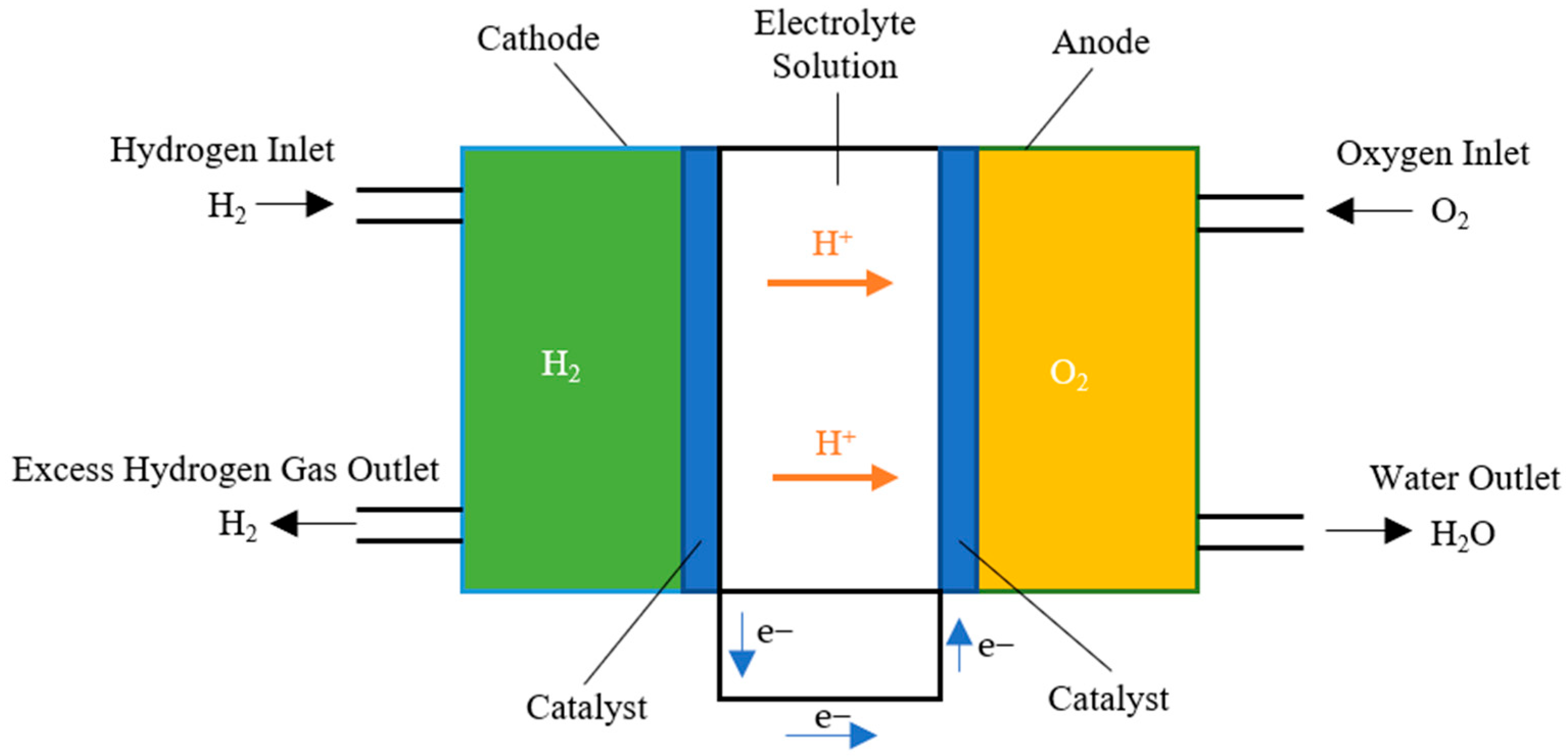
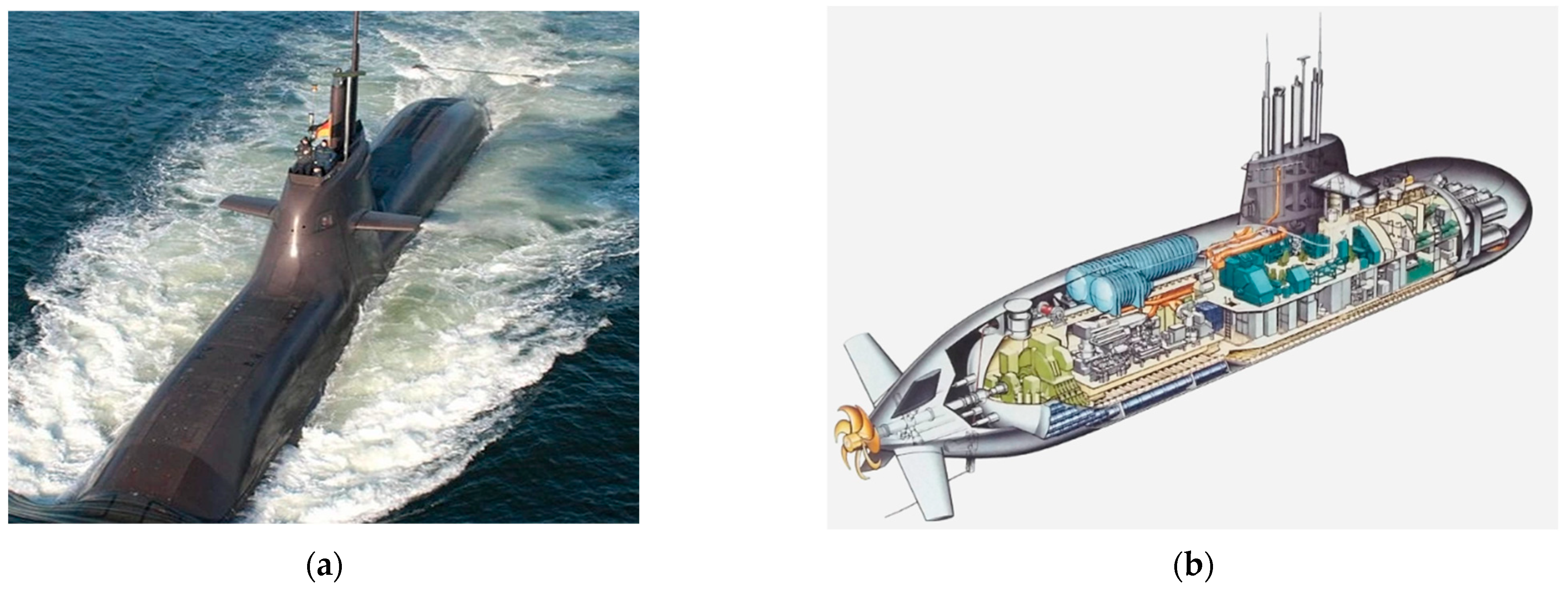

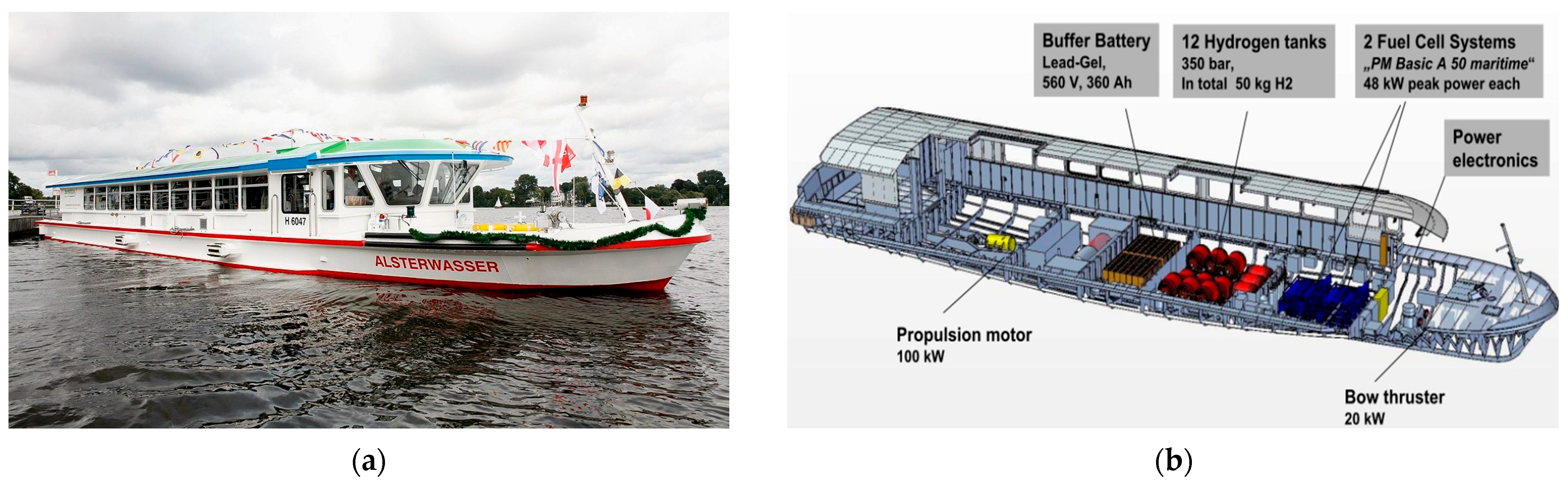
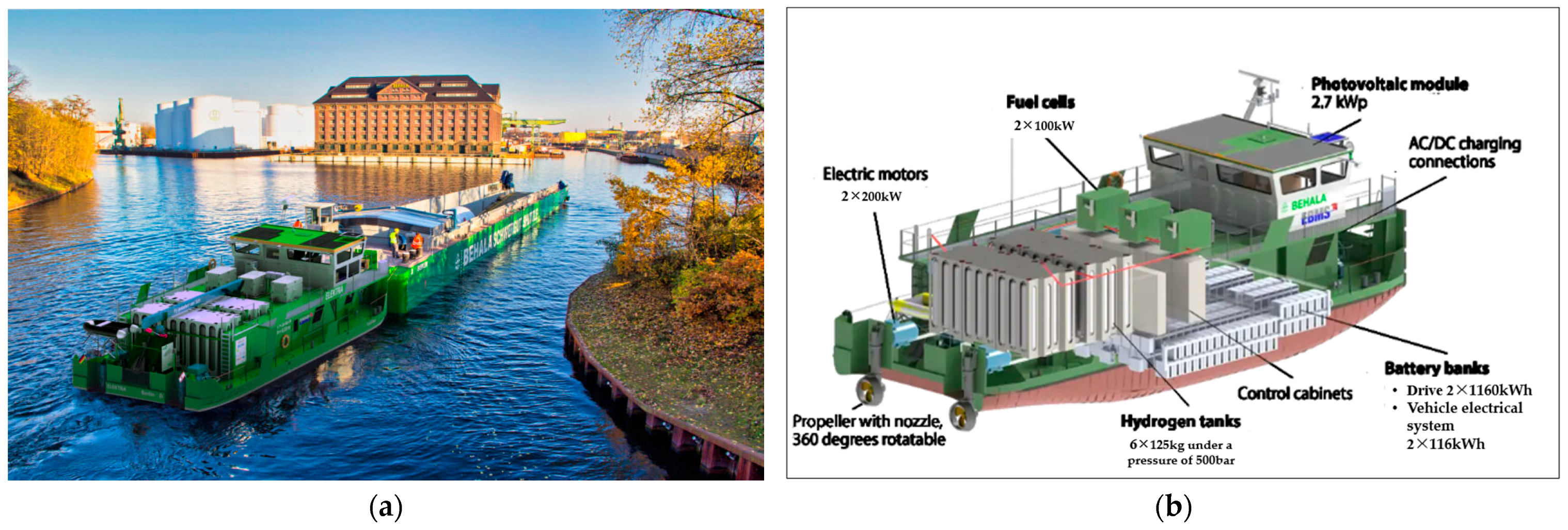
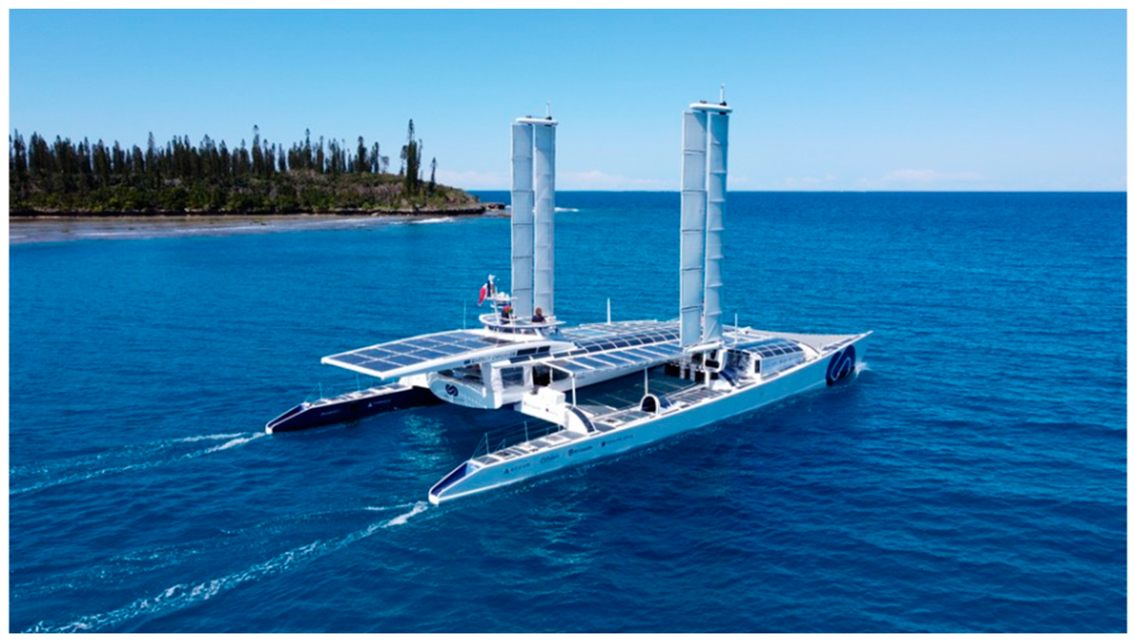


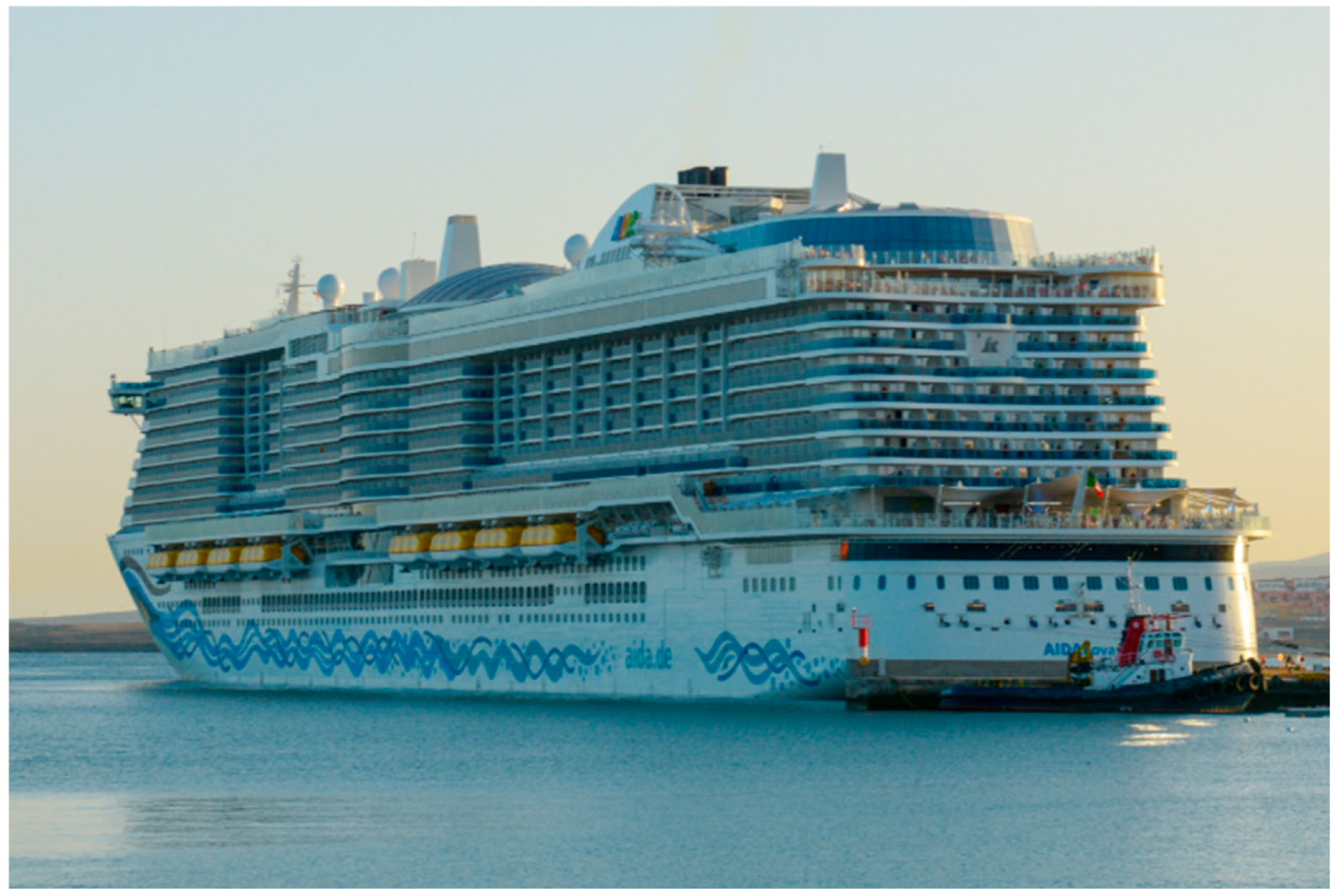

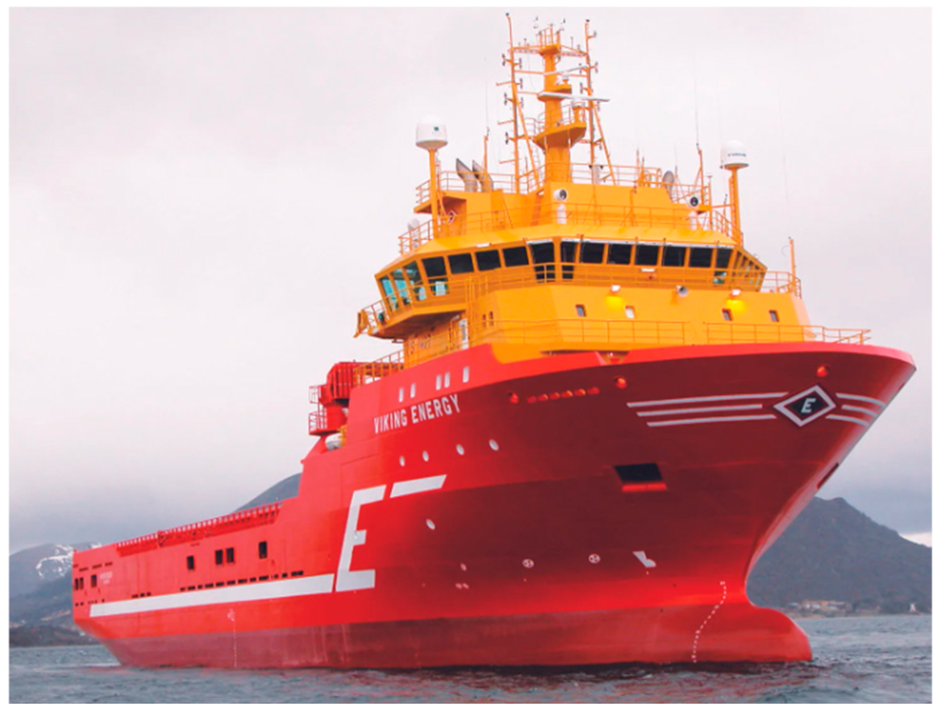


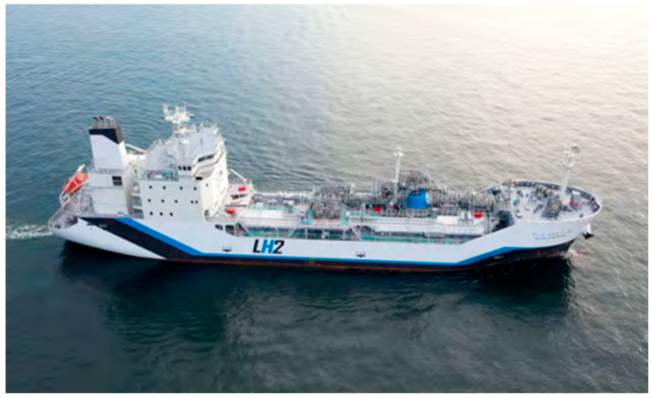
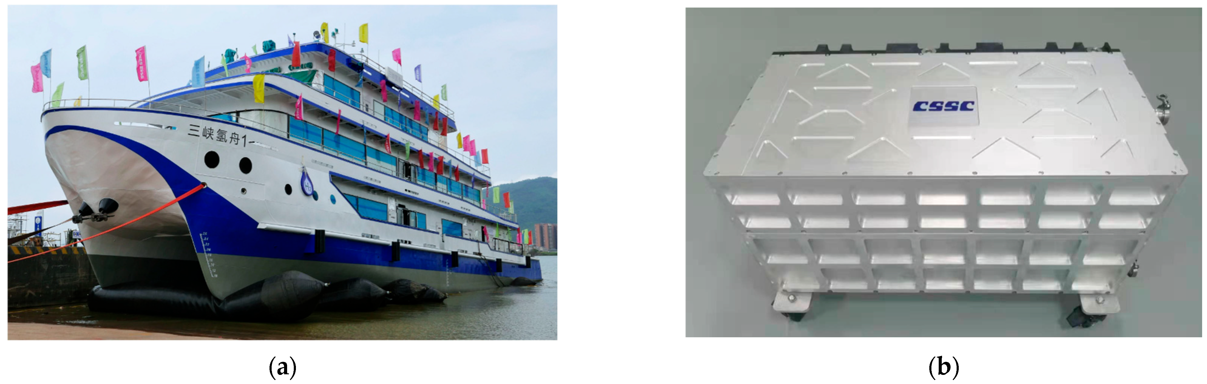


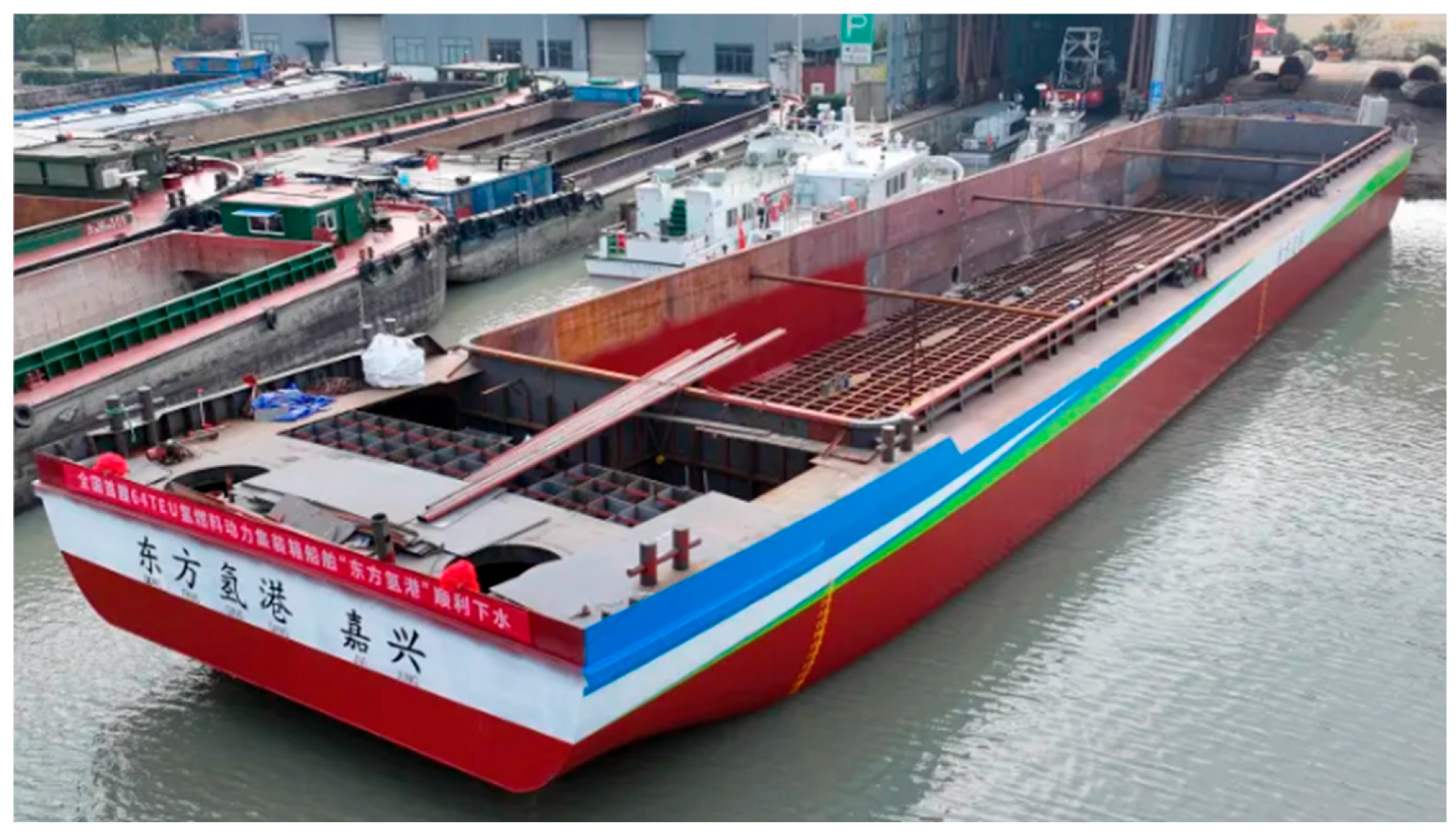
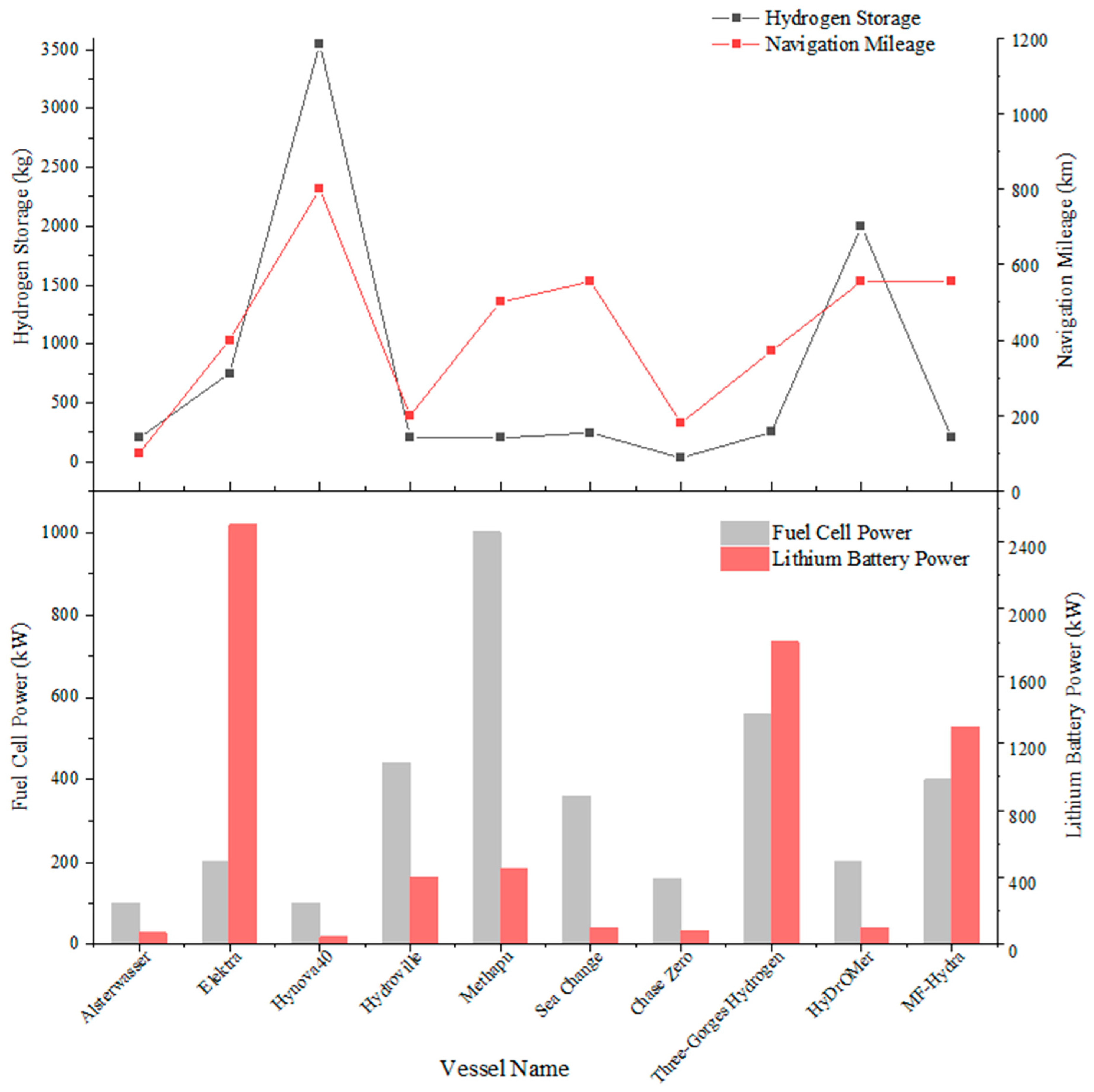
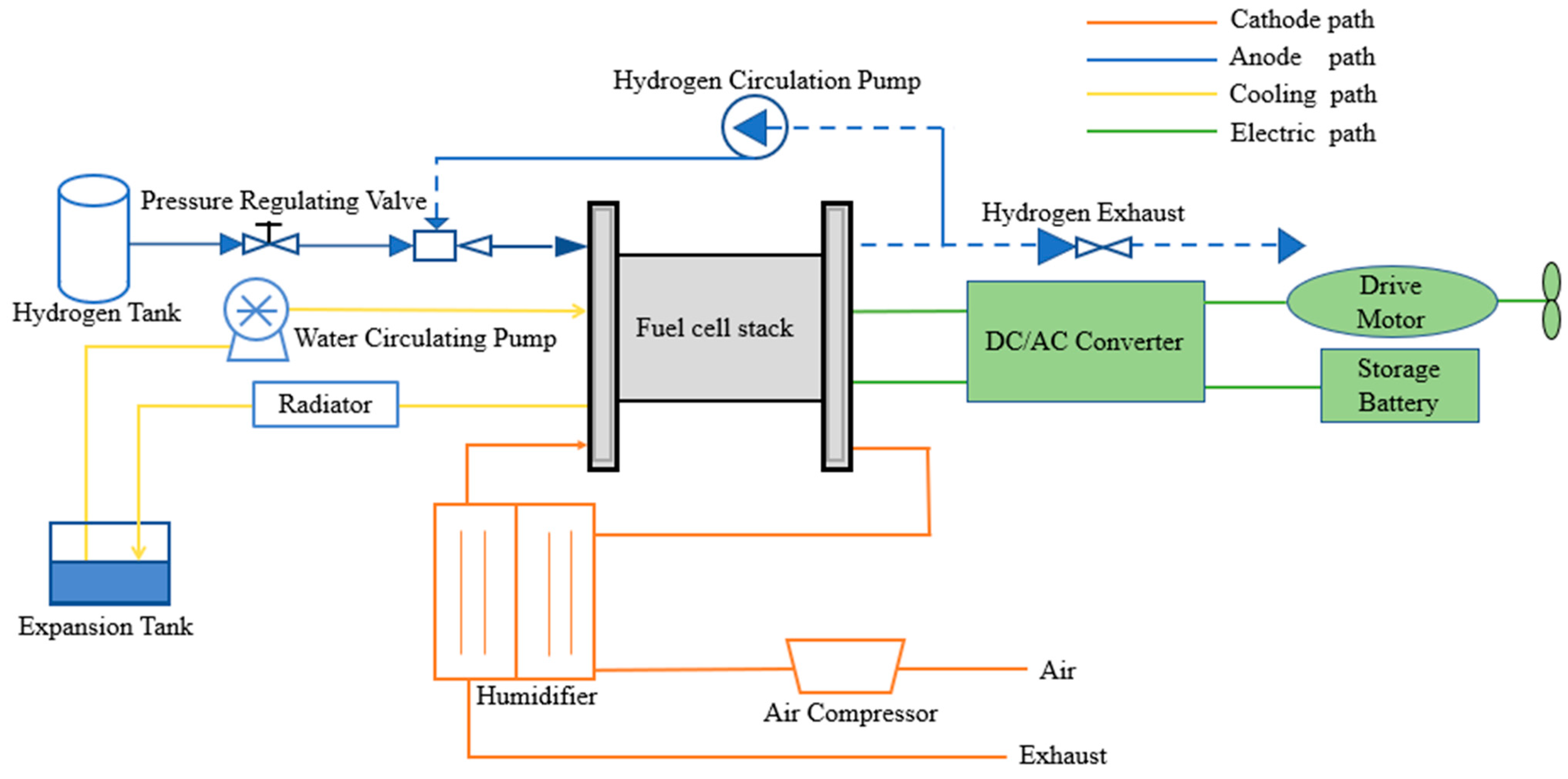

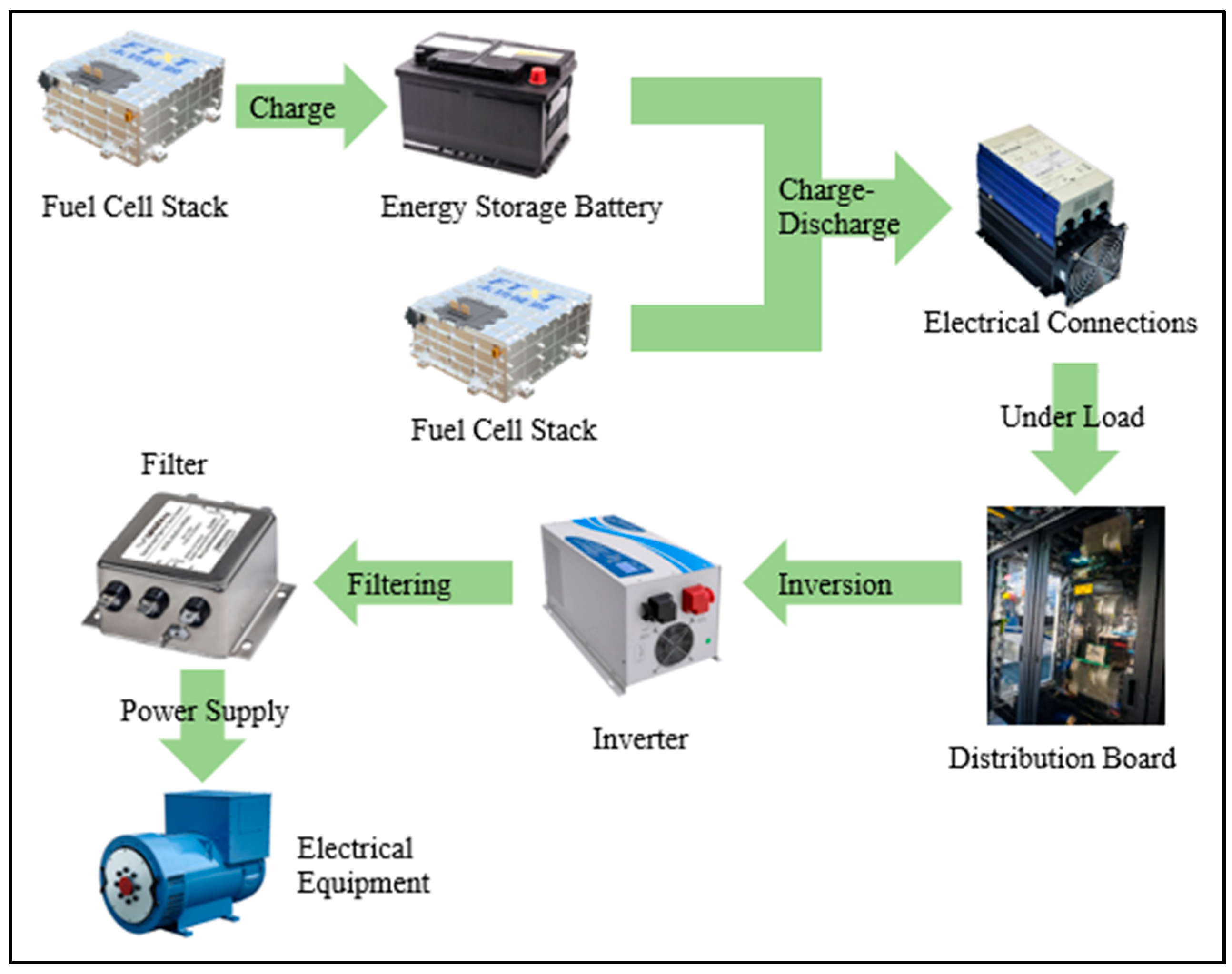
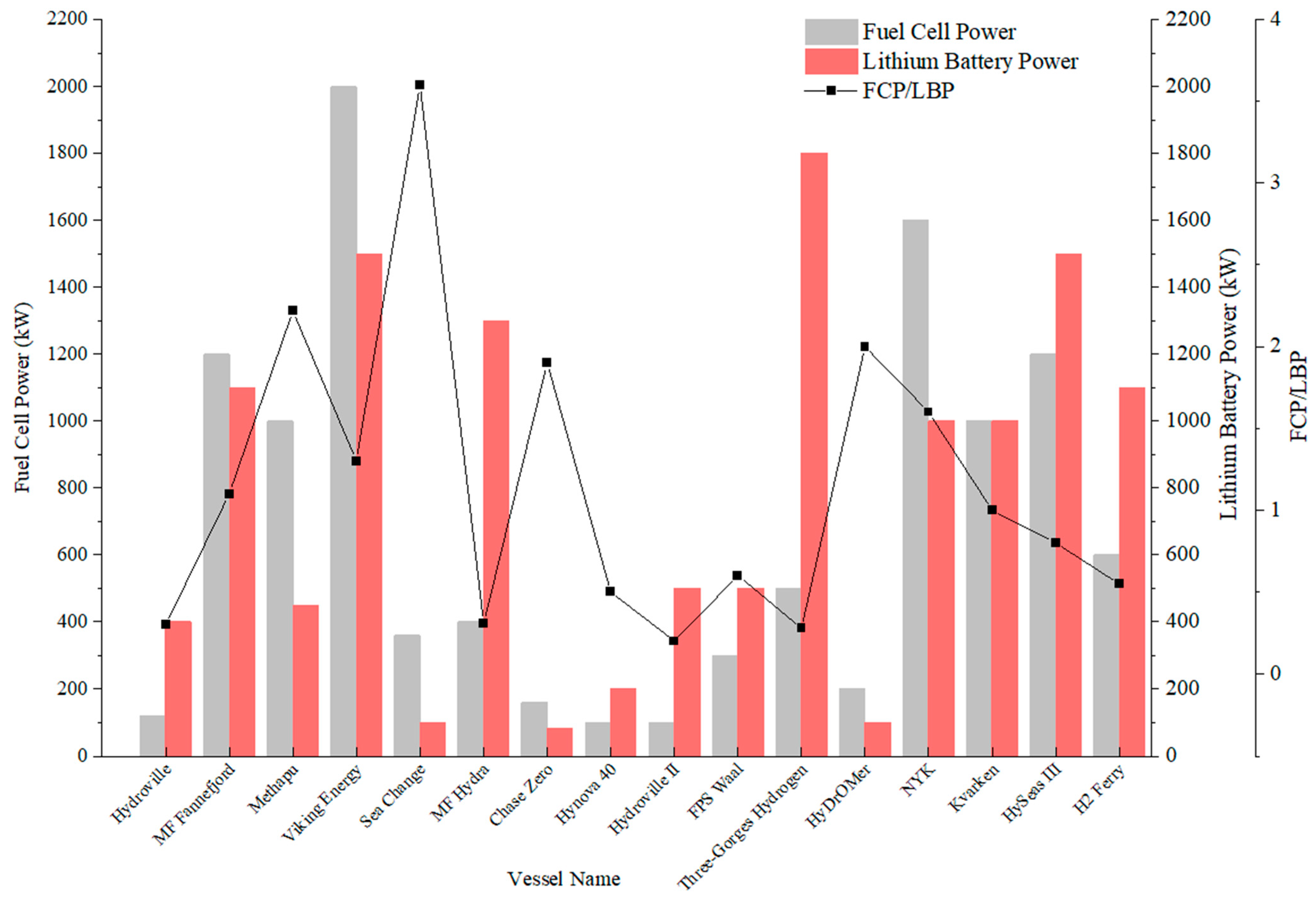
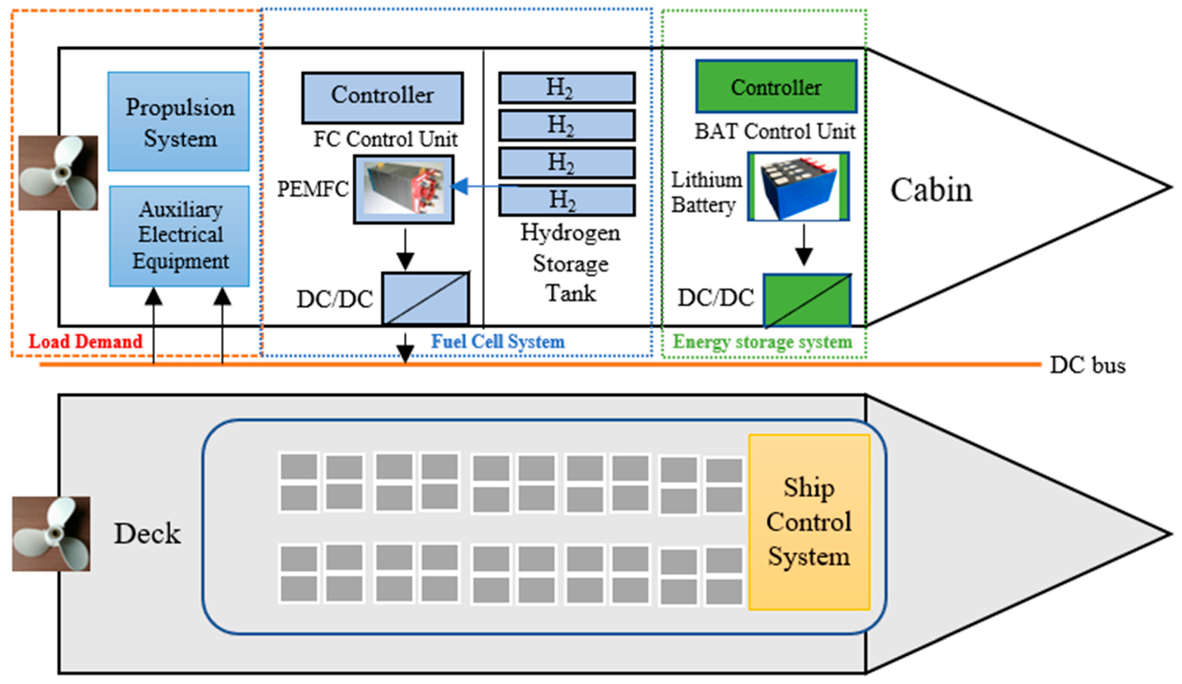
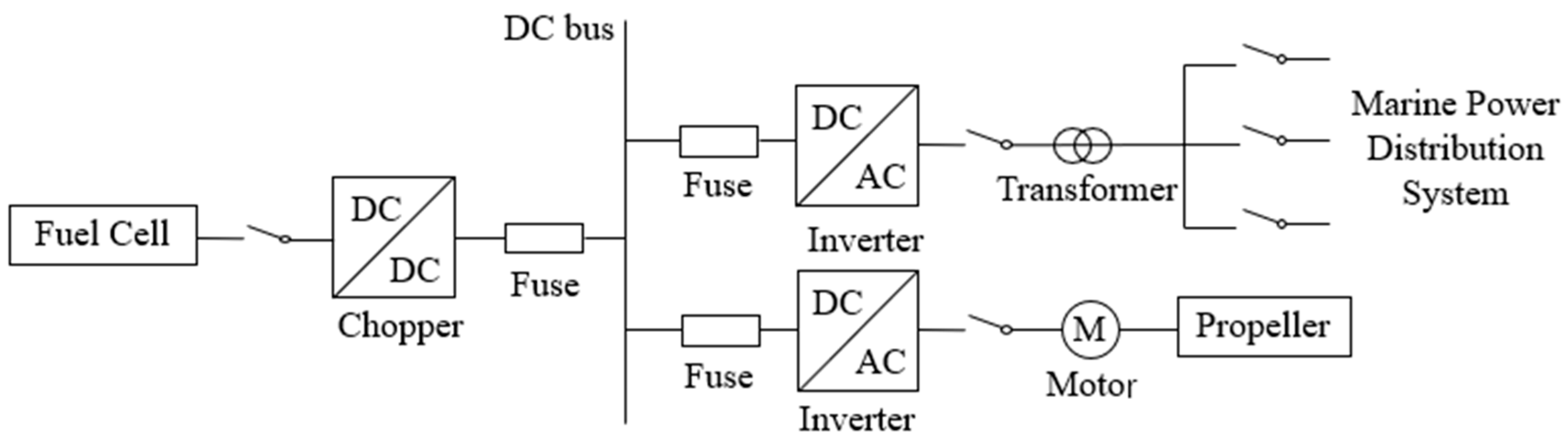
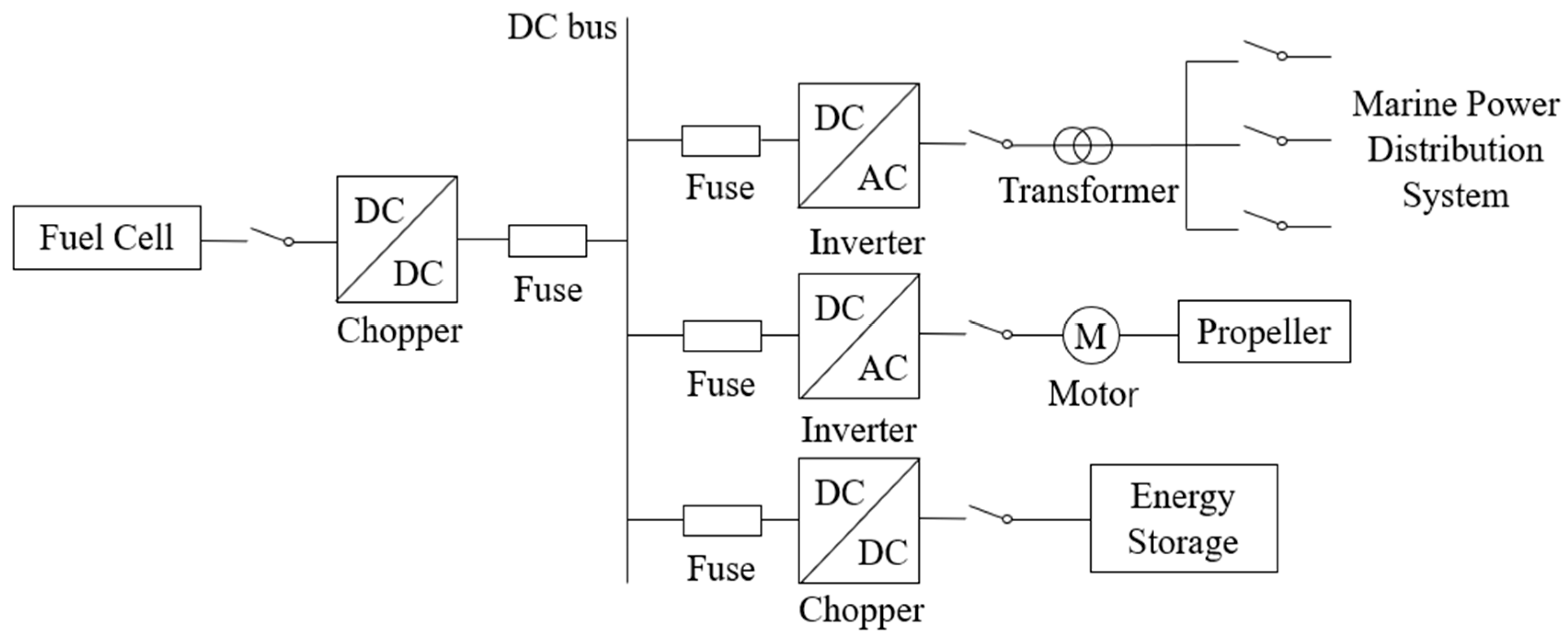
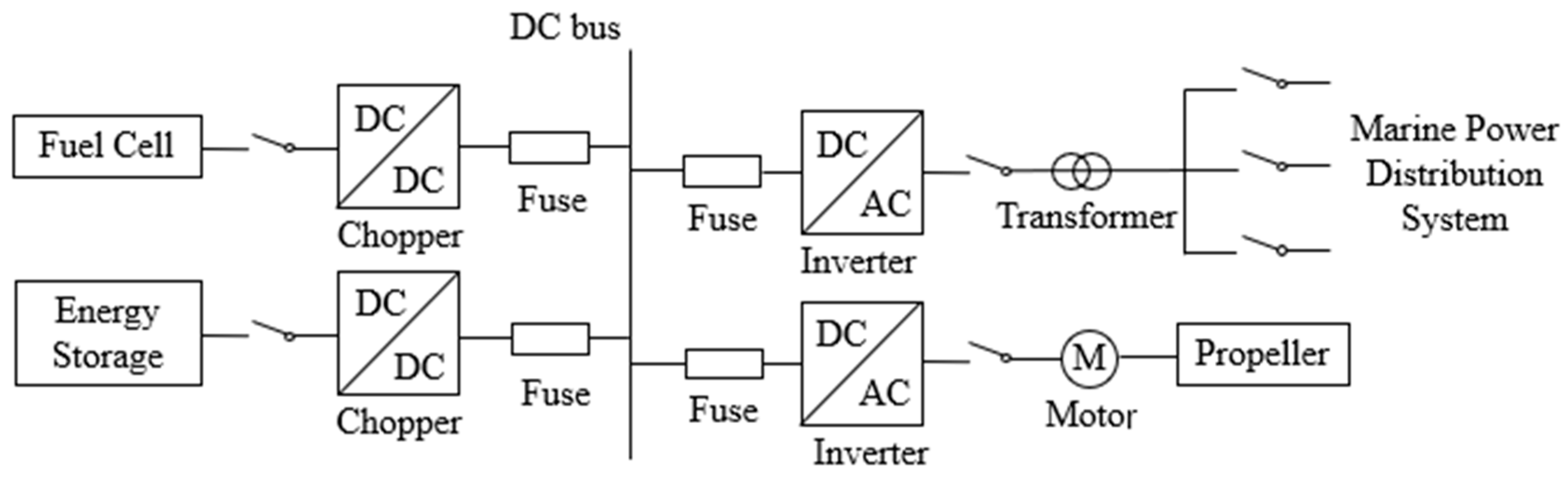
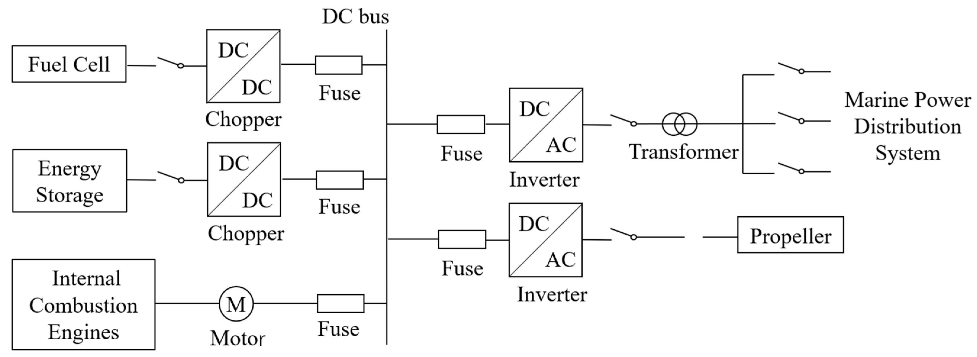


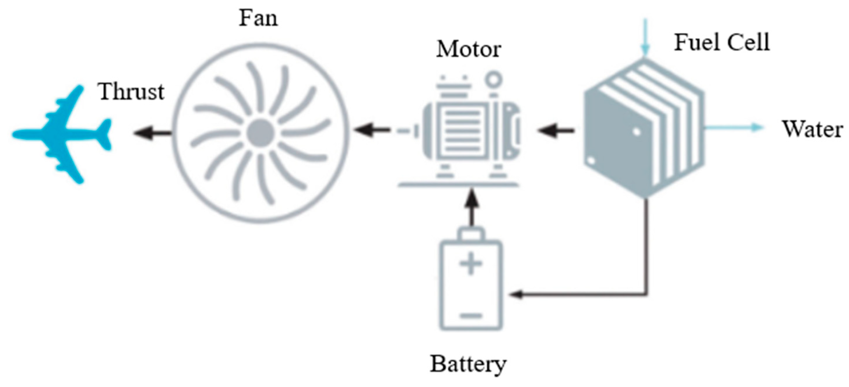
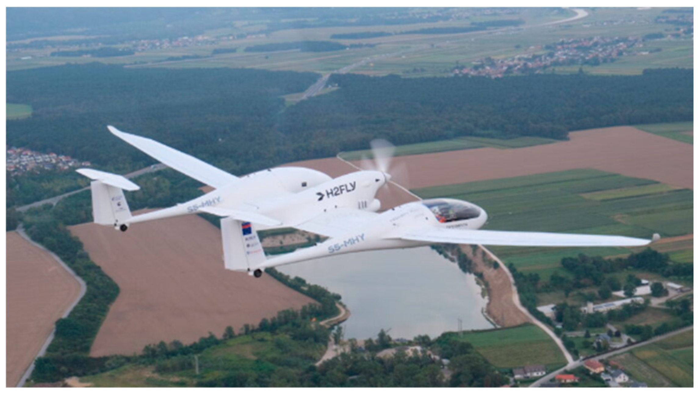
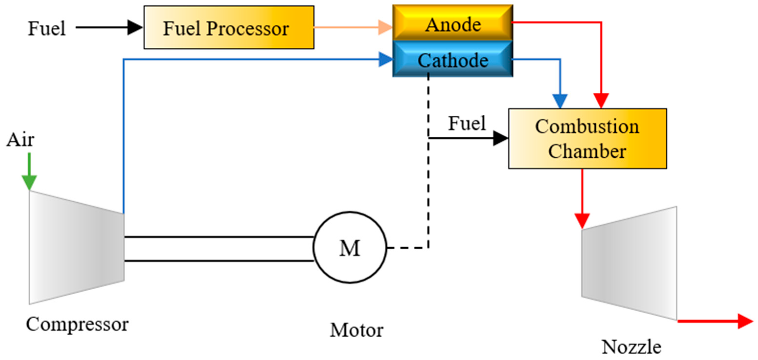
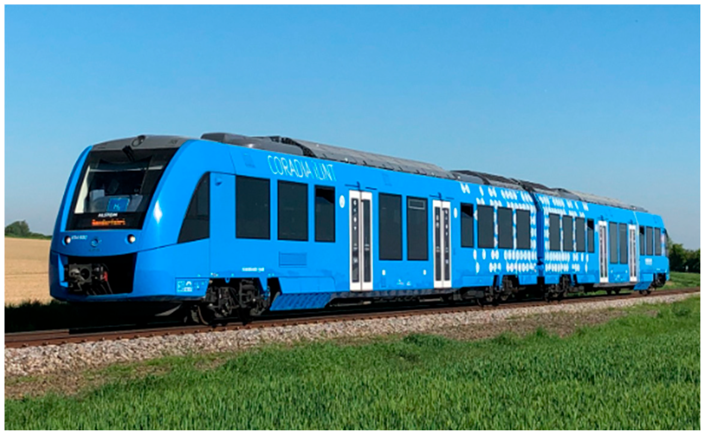
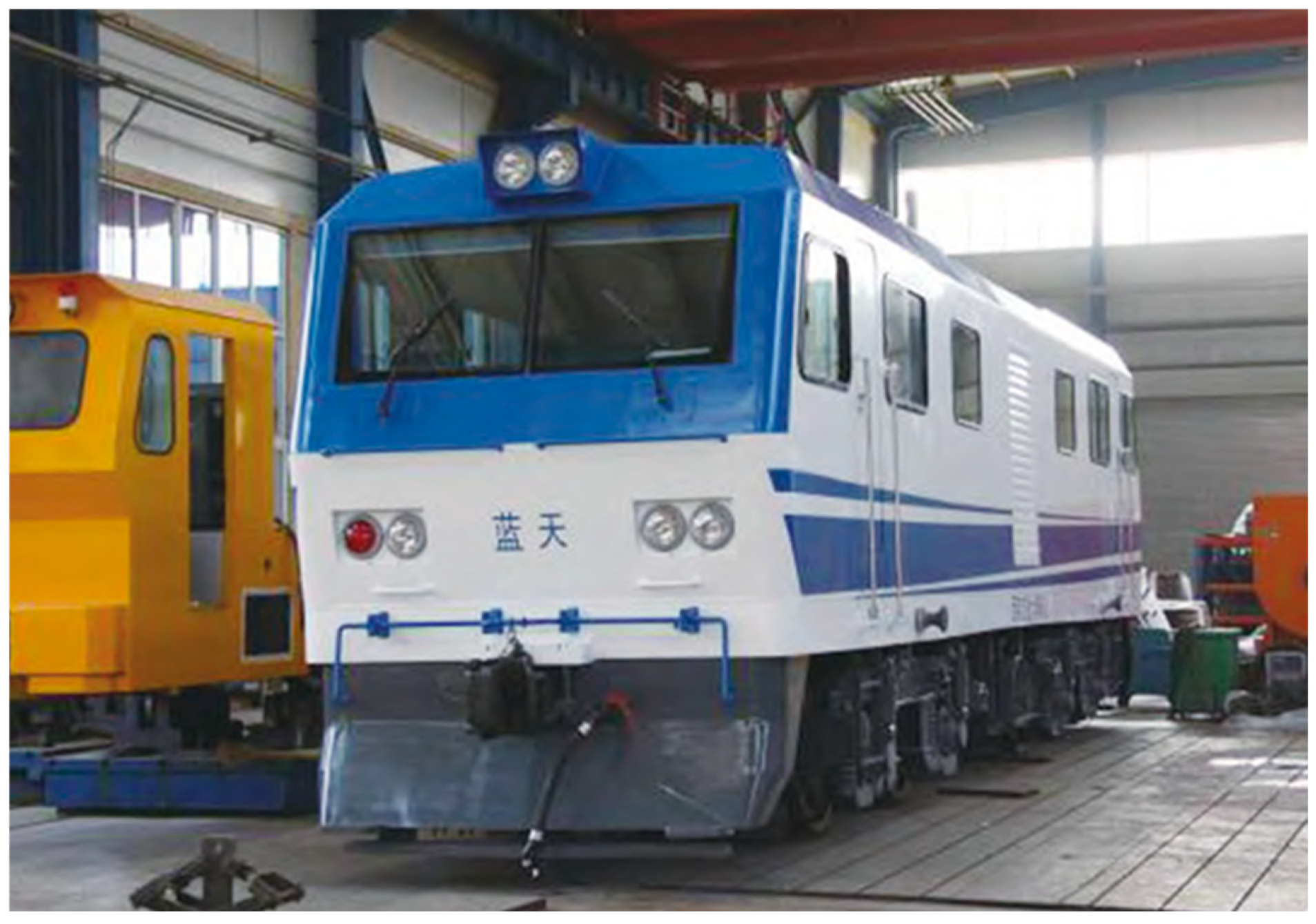
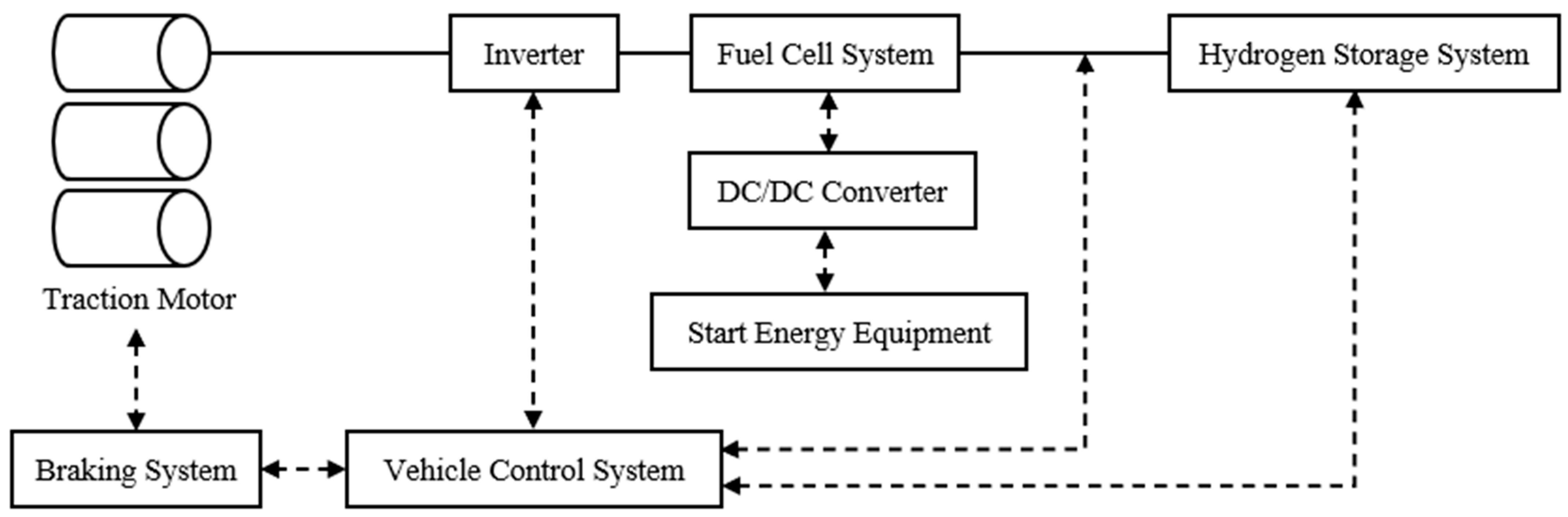
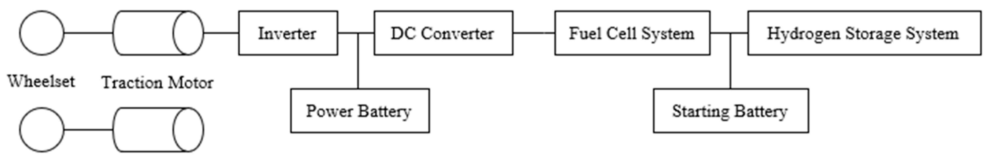
Disclaimer/Publisher’s Note: The statements, opinions and data contained in all publications are solely those of the individual author(s) and contributor(s) and not of MDPI and/or the editor(s). MDPI and/or the editor(s) disclaim responsibility for any injury to people or property resulting from any ideas, methods, instructions or products referred to in the content. |
© 2025 by the authors. Licensee MDPI, Basel, Switzerland. This article is an open access article distributed under the terms and conditions of the Creative Commons Attribution (CC BY) license (https://creativecommons.org/licenses/by/4.0/).