Article

Studying the Impact of the Load Distribution Ratio on the Unsteady Performance of a Dual-Stage Pump-Jet Propulsor

by
Jiansheng Zhang
1,
Ning Liang
1,
Jianwei Zhang
1,
Linlin Cao
1,*,
Dazhuan Wu
1,
Wei Zhao
2 and
Hanqiao Han
2
1
College of Energy Engineering, Zhejiang University, Hangzhou 310027, China
2
Wuhan Second Ship Design and Research Institute, Wuhan 430064, China
*
Author to whom correspondence should be addressed.
J. Mar. Sci. Eng. 2025, 13(4), 726; https://doi.org/10.3390/jmse13040726
Submission received: 16 February 2025 / Revised: 31 March 2025 / Accepted: 2 April 2025 / Published: 5 April 2025
(This article belongs to the Section Ocean Engineering)

Abstract

:
This study investigated the impact of different load distribution ratios between two rotors on the unsteady performance of dual-stage pump-jet propulsors using Computational Fluid Dynamics (CFDs) and experimental methods. The Shear Stress Transport (SST) k-ω model was employed to solve turbulence problems, and the numerical simulation method used was validated. The following conclusions were drawn: Different load distribution ratios of the dual-stage rotors have no significant impact on the overall propulsion performance of the propulsor. As the load distribution ratio is aft-shifted, the axial unsteady force of the entire propulsor continuously decreases, with a reduction of up to 53.6%. This is due to the gradual reduction in the energy of the first-stage rotor, leading to a more uniform Blade-Passing Frequency Velocity Harmonic Coefficient (BPFVHC) in front of the second-stage rotor, thereby gradually reducing the unsteady force of the second-stage rotor. The experimental results also indicate that the aft-shifted load model can reduce the sound pressure level of the propulsor. Compared to the prototype propulsor, the sound pressure level at the Blade-Passing Frequency decreases by 6.67 dB, or about 78.5%, in sound energy. This study has important implications for the low-excitation design of dual-stage pump-jet propulsors.

1. Introduction

Propellers are crucial propulsion devices for ships and underwater vehicles, among which pump-jet propulsors (PJPs) represent a more advanced generation [1]. PJPs feature a specialized structure that includes a stator, a rotor (or impeller), and a duct. Due to their multiple components and complex design, PJPs have become a research focus in underwater vehicle propulsion, offering reduced noise and improved energy efficiency, making them ideal for modern underwater applications [2,3,4,5].
The dual-stage PJP is a novel propulsor derived from the PJP. Compared to the traditional PJP, which consists of a stator, a rotor, and a duct, the dual-stage propulsor comprises five components: two-stage rotors, two-stage stators, and a duct. Similarly to counter-rotating propulsors, the core concept of the dual-stage propulsor is to divide a single rotor into two rotors, which can effectively reduce blade load and rotational speed, thereby achieving reduced vibration noise and improved cavitation resistance under the same advanced speed conditions [6]. Studies have shown that compared to traditional single-rotor pumps with the same design parameters, counter-rotating propulsors have higher efficiency, more compact size, more stable performance curves, and better cavitation resistance [7,8,9,10]. Therefore, introducing the dual-stage propulsor concept into PJPs also holds promise for improving vibration and noise performance.
However, propulsors often operate in inflow fields that vary with time and space during actual operation, inducing load changes on the rotor blades and subsequently causing unsteady forces on the drive shaft. These unsteady forces are not only the main excitation source of the direct radiated noise from the rotor [11] but also transmit through the shaft system to the vehicle’s surface, causing vibrations and acoustic radiation in the stern and even internal structures [12]. For underwater vehicles, the level of radiated noise is not only a key indicator of their acoustic performance but also a source of interference affecting the performance of sonar equipment. Therefore, it is crucial to reduce the unsteady performance of PJPs.
Currently, methods to study propulsor unsteady forces mainly include theoretical calculations, model tests, and numerical simulation methods. Model testing is a commonly used approach, with the most influential unsteady forces test conducted by Jessup et al. [13] in a water tunnel. Recently, Tong et al. [14] also measured the unsteady forces of post-rudder propellers using a self-developed high-resolution unsteady dynamometer. However, due to the small magnitude of the unsteady forces (with pulsations typically being one-thousandth of the thrust) and the continuous rotation of the blades, experimental measurements are challenging. Therefore, an increasing number of researchers are using numerical simulation methods to study unsteady propeller forces. Currently, commonly used numerical simulation methods in PJP research include the Reynolds-Averaged Navier–Stokes (RANS) method [15,16] and hybrid models based on Reynolds-Averaged Navier–Stokes/Large Eddy Simulations (RANS/LESs), such as Scale-Adaptive Simulation (SAS), Delayed Detached Eddy Simulation (DDES), Improved Delayed Detached Eddy Simulation (IDDES) [17,18], and the LES method [19,20]. Depending on the research object, researchers use different numerical methods. To study the unsteady forces of propulsors, the RANS method is often chosen by many researchers due to its fast and accurate calculation advantages [21,22,23]; for studying broadband unsteady forces and vortex structures, the Detached Eddy Simulation (DES) hybrid model and LES method are also widely used by many researchers [24,25,26]. The main advantage of the RANS method lies in its high computational efficiency, making it one of the most widely used turbulence modeling approaches in the field of fluid machinery [27]. In the context of underwater propulsors, it is also a commonly adopted method. Particularly in this study, which focuses on tonal unsteady forces in the propulsor, RANS is capable of accurately capturing the tonal unsteady forces generated by the combined effects of non-uniform wake and blade rotation. The discrepancy between RANS simulation results and experimental measurements is typically within 5%, indicating a high level of computational accuracy. Moreover, compared to LES, RANS significantly reduces mesh requirements and computational costs.
In the study of vibration and noise reduction for propellers, reducing the unsteady forces on the rotor is the most crucial and fundamental method. The control methods for the unsteady forces of PJPs can be mainly divided into four aspects: wake formation [28], wake control [29,30], blade response [21,31], and transmission path [32,33]. Shi et al. [34] found that the sound pressure level characteristics of flow-induced noise and unsteady forces are identical using CFD, the coupled Finite Element Method (FEM), and Boundary Element Method (BEM). The main peaks in the sound pressure level of flow-induced noise correspond to the typical modal frequencies and characteristic frequencies of unsteady forces. Li et al. [24] used Embedded Large Eddy Simulation (ELES) to study the effects of duct parameters on the unsteady forces of PJPs, revealing the variation patterns of unsteady forces with duct parameters. Currently, many scholars have conducted research on the unsteady forces of PJPs, but most remain at the stage of experimental measurement and numerical analysis, describing phenomena. There are relatively few studies on reducing the unsteady forces of PJPs and even fewer on reducing the unsteady forces of dual-stage PJPs, necessitating further research.
This study addresses the gap in research on reducing the unsteady forces of dual-stage PJPs. Focusing on dual-stage PJPs and aiming to reduce unsteady forces, it explores the impact of load distribution ratios between the two rotors on unsteady performance. The structure of this paper is as follows: Section 2 describes the research object, numerical simulation methods, and their validation; Section 3 uses spectral analysis and other methods to investigate the effects of different load distribution ratios between the two rotors on the unsteady performance of the dual-stage PJP, including unsteady forces and radiated noise; finally, Section 4 presents the conclusions and future work.

2. Numerical Calculation Method

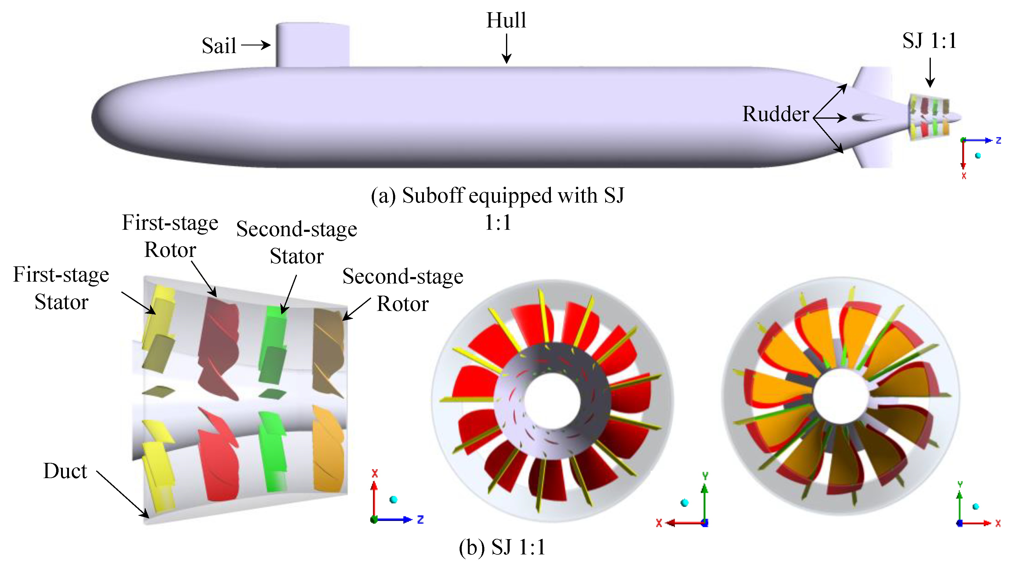
2.1. Research Object

The subject of this study is a fully appended suboff standard model and its corresponding dual-stage PJP, which is independently designed, as shown in Figure 1. The suboff model has been widely used in numerous studies, with a hull length Lsub of 4.356 m, a hull diameter Dsub of 0.508 m, and complete appendages, including a sail and four rudders. The dual-stage PJP consists of five components: a first-stage stator, a first-stage rotor, a second-stage stator, a second-stage rotor, and a duct. The initial model is named SJ 1:1 because both rotors share the same load distribution ratio. All cases in this study were conducted at a design speed of V = 18 knots (9.259 m/s).
The design of the dual-stage PJP is similar to that of a conventional pre-swirl stator pump jet based on the lifting line theory and CFD iteration. The blade design adopts the radial independence assumption, where the stator and rotor are divided into several annular sections along the radial direction, and each section is designed separately. The stators and rotors of the dual-stage PJP were designed using ANSYS BladeGen 2024 R1; the duct was modeled using CATIA P3 V5-6R2020; and the final assembly with the SUBOFF model was completed in CATIA P3 V5-6R2020. The specific design process is given as follows: First, appropriate meridional planes are determined, which define the axial start and end positions of the blades. Then, using the lifting line theory and predetermined radial load distribution, the inlet and outlet angles of the blades at several characteristic sections are calculated. At the initial design stage, the specific inflow velocity distribution is unknown, which may result in a discrepancy between the actual thrust of the preliminary rotor design and the design value. However, CFD calculations can provide accurate velocity distributions and assist in subsequent design iterations. After several iterations, the model gradually approaches the initial design intent, resulting in the final SJ 1:1 model. The main parameters are shown in Table 1. The notable characteristic of this model lies in the closely balanced torque of the two-stage rotors, signifying a power ratio of 1:1.
This study primarily investigates the impact of load distribution ratios on the unsteady performance of dual-stage PJPs. The primary difference between the dual-stage propulsor and the conventional pre-swirl stator pump-jet lies in its two rotors, making the load distribution ratio between the two rotors a significant feature. Different load distribution ratios affect the working capacity of each rotor and the overall unsteady performance of the propulsor. Therefore, based on the initial SJ 1:1 model, four additional models with load distribution ratios of 2:1, 1.5:1, 1:1.5, and 1:2 were designed, resulting in a total of five models with which to understand the variation in unsteady force under different load distribution ratios. The number of blades for the first-stage and second-stage rotors was 11 (NR = 11), and the number of blades for the first-stage and second-stage stators was 13 (NS = 13). Due to the numerous components of the dual-stage PJP and various factors affecting blade load distribution, such as radial loading methods and camber distribution, it was essential to isolate the impact of load distribution ratios on the unsteady performance of the propulsor. Therefore, when adjusting each model, only the inlet and outlet angles of the stators and rotors were modified to achieve the desired load distribution ratios. The blade outlet angle of each model is shown in Table 2. Although the angle intervals are not uniform, they result from the actual design process required to maintain consistent proportional changes in the load distribution ratio across all cases.

2.2. Numerical Simulation Methods

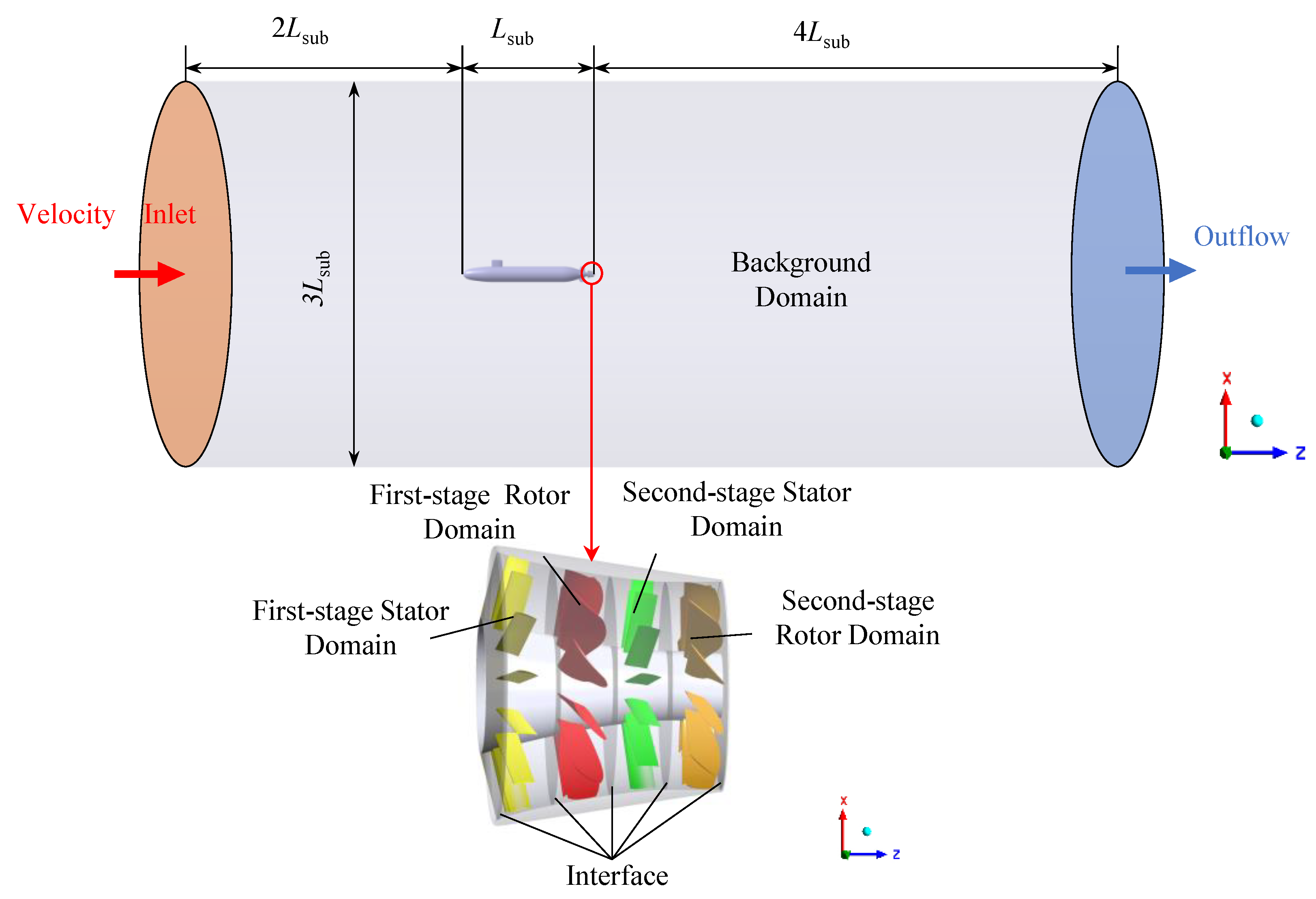
2.2.1. Computational Domain and Mesh Generation

The vehicle studied in this paper needed to advance in open water, necessitating a large computational domain. As shown in Figure 2, the computational domain was divided into three stationary domains (one background domain and two stator domains) and two rotating domains (two rotor domains). Data transfer between these domains was achieved through interfaces. The inlet and outlet of the background domain were located 2 Lsub upstream of the bow and 4 Lsub downstream of the stern, respectively. The cross-section was circular with a diameter of 3 Lsub.
The background domain was meshed with polyhedral grids using Fluent meshing software, and the stator and rotor domains were meshed with structured hexahedral grids using Turbo Grid software, as shown in Figure 3. The height of the near-wall layer mesh was independently set to maintain y+ at around 60, meeting the conditions for resolving the boundary layer flow using the SST k-ω model with the ω equation. To ensure computational accuracy and efficiency, the total number of mesh cells was 14.53 million, with 7.3 million in the background domain, 1.29 million in the first-stage stator domain, 2.32 million in the first-stage rotor domain, 1.32 million in the second-stage stator domain, and 2.3 million in the second-stage rotor domain.

2.2.2. Computational Methods and Boundary Conditions

The dual-stage PJP in this study operated underwater in non-cavitating conditions with a low Mach number, allowing the flow to be considered a single-phase incompressible flow. Therefore, the SST k-ω turbulence model was used to solve the RANS equations [35]. The SST k-ω turbulence model employed a blending function to apply the Wilcox k-ω model within the boundary layer and a suitably transformed k-ε model in the turbulence core region outside the boundary layer. The SST k-ω turbulence model can accurately predict a wider range of flows and can effectively predict the onset of fluid separation and the size of the separation zone under adverse pressure gradient conditions in particular. Due to the inevitable flow separation in the internal and surrounding flow fields of the propulsor during operation, the SST k-ω turbulence model is also widely used in the study of PJPs [4,22,36].
The finite volume commercial code ANSYS FLUENT 2024 R1 was utilized to solve the continuity, momentum, and turbulence equations. The numerical simulation in this study was divided into steady-state and transient calculations. The steady-state calculation was used for the rapid assessment of the hydrodynamic performance of the dual-stage propulsor and provided initial values for the transient calculation. The convergence of the steady-state calculation was determined primarily by velocity and residuals, achieving a steady state with residuals less than 10−4 after 3000 iterations. The decay process of the residuals is shown in Figure 4. The rotor domains were rotating domains, while the other domains were stationary, with the rotation of the rotor domains realized through a moving reference frame. A transient calculation was used to evaluate the transient performance of the dual-stage propulsor, such as unsteady force characteristics. To accelerate the convergence process, the transient calculation first used large time steps (10 deg) to compute 36 rotor rotation cycles, then small time steps (1 deg) to compute 15 rotation cycles, ensuring sufficient time resolution. Data from the last 6 cycles were used for subsequent analysis.
Regarding boundary conditions, the inlet boundary and background domain wall were both set to velocity inlet conditions, with the velocity magnitude matching the design speed but in the opposite direction. As the rotors operated under deep-sea conditions, cavitation was not considered in this study. Therefore, the outlet boundary was set as a pressure outlet with a reference pressure of 1 for the atmosphere. All the walls of the suboff and dual-stage PJP were set to no-slip conditions. The rotational speed of the rotor hub surfaces was set to 0 rpm, which is consistent with the actual conditions.

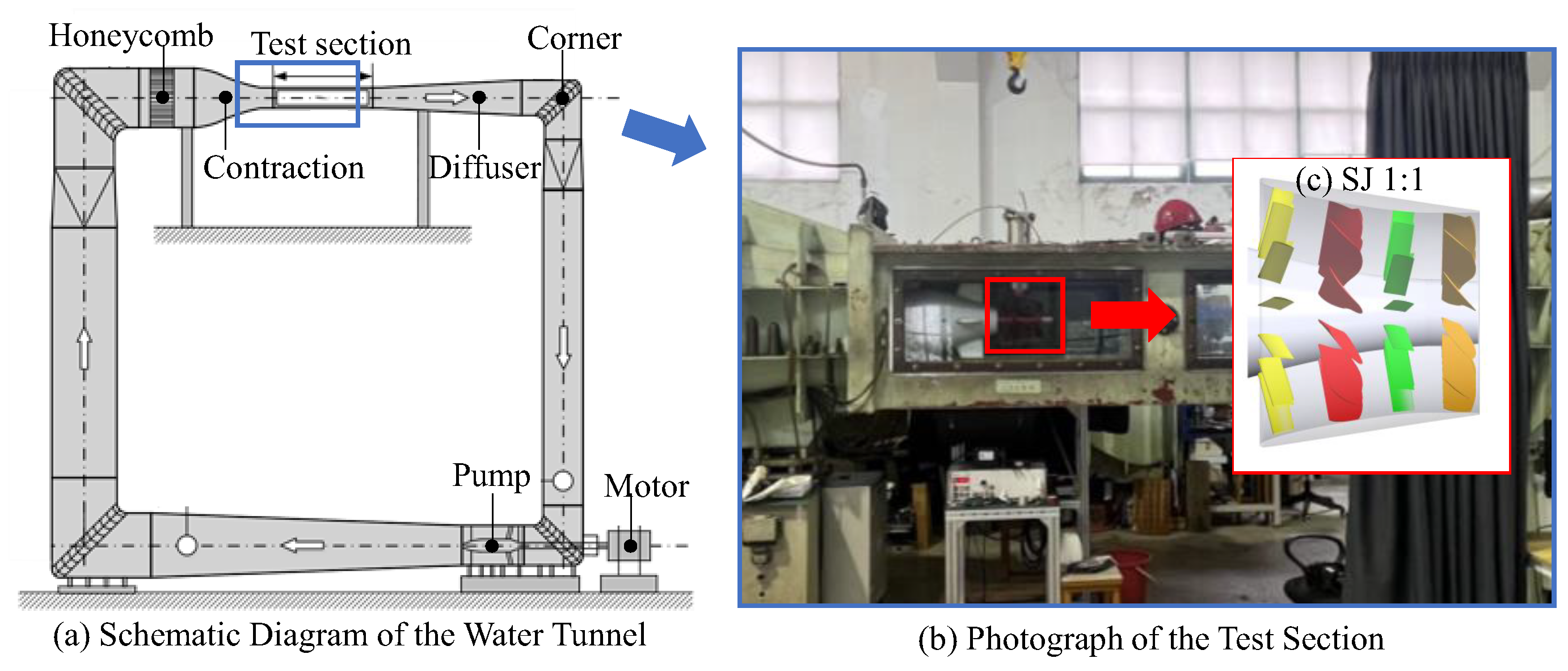
2.3. Numerical Method Validation

This study focuses on the unsteady performance of the PJPs; thus, the numerical simulation methods were primarily validated through verification related to the suboff and the propulsor.

2.3.1. Suboff Validation

Due to the significant impact of wall boundary layer resolution accuracy on the drag of the suboff, the dimensionless distance y+ of the first mesh layer on most regions of the suboff surface was maintained at around 60 in the calculations. The overall y+ distribution of the suboff is shown in Figure 5. This meets the criterion proposed by Menter [37], which suggests that a y+ value below 300 is sufficient to achieve acceptable predictive accuracy in simulations of industrial flows. Besides the boundary layer, the global mesh density also significantly affects the calculated drag value of the suboff, and the effect of the total mesh number on drag was studied. The drag value at a similar speed (17.79 knots) to this study, provided by Liu [38], was used as a reference. The calculations used the same boundary conditions and computational domain as shown in Section 2.2.2, with the difference being the removal of the dual-stage PJP. As shown in Table 3, the calculated drag values approached the reference value as the mesh number increased, with overall deviations remaining small, indicating the reliability of the calculated values. Therefore, to balance computational accuracy and cost, the mesh size equivalent to Mesh 2, with a total of 7.45 million cells, was selected for subsequent calculations and analyses.

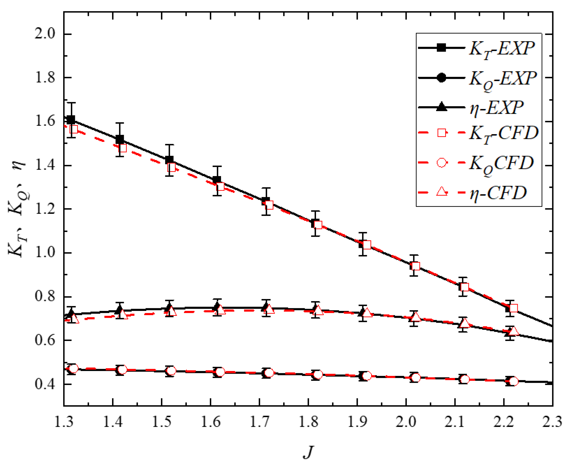
2.3.2. Propulsor Verification

The propulsor verification was mainly divided into the verification of the steady-state hydrodynamic performance and the verification of the transient time step.
The verification of the steady-state hydrodynamic performance of the propulsor was primarily achieved by comparing the experimental results with numerical simulation results to validate the accuracy of the numerical simulation. First, model tests were conducted in a large cavitation tunnel, measuring key parameters such as thrust, torque, and the efficiency of the propulsor under different operating conditions. These experimental data provide reliable reference standards for numerical simulations. By comparing and analyzing the experimental results with the numerical simulation results, the accuracy and reliability of the numerical simulations were assessed. This method can effectively verify the accuracy of the numerical simulations, ensuring that they accurately reflect the hydrodynamic performance of the propulsor under actual operating conditions, thereby providing a scientific basis for subsequent internal flow field analysis and the design optimization of the propulsor. The experiments in this study were conducted in the large cavitation tunnel at the Shanghai Ship and Shipping Research Institute, as shown in Figure 6a. The dual-stage PJP used in the experiments is presented in Figure 6b. The tunnel flow speed was continuously adjustable within the range of 3~12 m/s. The flow speed in the working section was measured by a Venturi flowmeter, with an uncertainty of 0.5% FS (full scale). The rotational speed, thrust, and torque of the dual-stage PJP rotor were synchronously measured by a J25 dynamometer, with ranges of 0~4000 rpm, 0~3 kN, and 0~150 Nm, respectively, and an uncertainty of 0.1% FS. The thrust of the stator and duct was measured by a five-component force balance, with a range of 0~400 N and an uncertainty of 0.01%.
Both the experiments and simulations adjusted the advance coefficient by fixing the rotor speed and varying the inflow velocity. The comparison between the experimental and simulation results is shown in the figure, with the dimensionless parameters defined in the equations.
J = V n D
K T = T ρ n 2 D 4
K Q = Q ρ n 2 D 5
  η = J 2 π K T K Q
In the equations, J represents the advance coefficient; V represents the inflow velocity; n represents the rotor speed (rps); K T and K Q represent the thrust coefficient and torque coefficient, respectively; and T and Q represent the total thrust and rotor torque, respectively.
As shown in Figure 7, the overall propulsion performance of the dual-stage PJP obtained from experiments and simulations matches well. The simulated K T , K Q , and η results fall within the 5% error bars of the experimental values, indicating that the simulation method used is reliable, laying a solid foundation for subsequent flow field analysis.
For transient calculations, the time step is a crucial factor affecting the solution accuracy, and it also significantly impacts the solving speed. Therefore, it is necessary to perform independent time step verification. In the study of rotating machinery like propulsors, the time step is usually related to the rotor’s rotation angle. This study used the physical times corresponding to rotor rotations of 2 deg, 1 deg, and 0.5 deg as different time steps for independence verification. The settings remained consistent with those described previously. The independence verification of the time step was primarily conducted by comparing the amplitude of the unsteady force, which has the most significant impact on transient performance. The results are shown in Table 4.
As shown in Table 4, the time step significantly affects the axial excitation force of each rotor, with the axial force of the second-stage rotor being more sensitive to changes in the time step. The results calculated with 2 deg per step time step clearly underestimate the amplitude of the axial excitation force. Although there is still some discrepancy between the results of 1 deg and 0.5 deg, considering the computational cost, this study selected a 1 deg per step time step for subsequent calculations. This choice, although sacrificing some accuracy in the axial excitation force calculation, represents a good balance between computational economy and accuracy.

3. Results and Discussion

3.1. Hydrodynamic Performance

The steady-state hydrodynamic performance of the five models is shown in Table 5. It can be observed that as the loads were aft-shifted, the overall head and propulsive efficiency of the propulsor changed very little, and the overall hydrodynamic performance remained relatively close.
Figure 8 shows the total pressure variation along the flow direction for each component of the propulsor under different load distribution ratios. This further visually demonstrates the energy growth distribution of each component. It can be observed that the overall working capacity of the five propulsors is relatively consistent, which corresponds with the total rotor head results in Table 5. However, the working capacity of the first-stage and second-stage rotors varies. The energy growth pattern also aligns with the design expectations: as the loads are aft-shifted, the working capacity of the first-stage rotor gradually decreases while that of the second-stage rotor gradually increases.

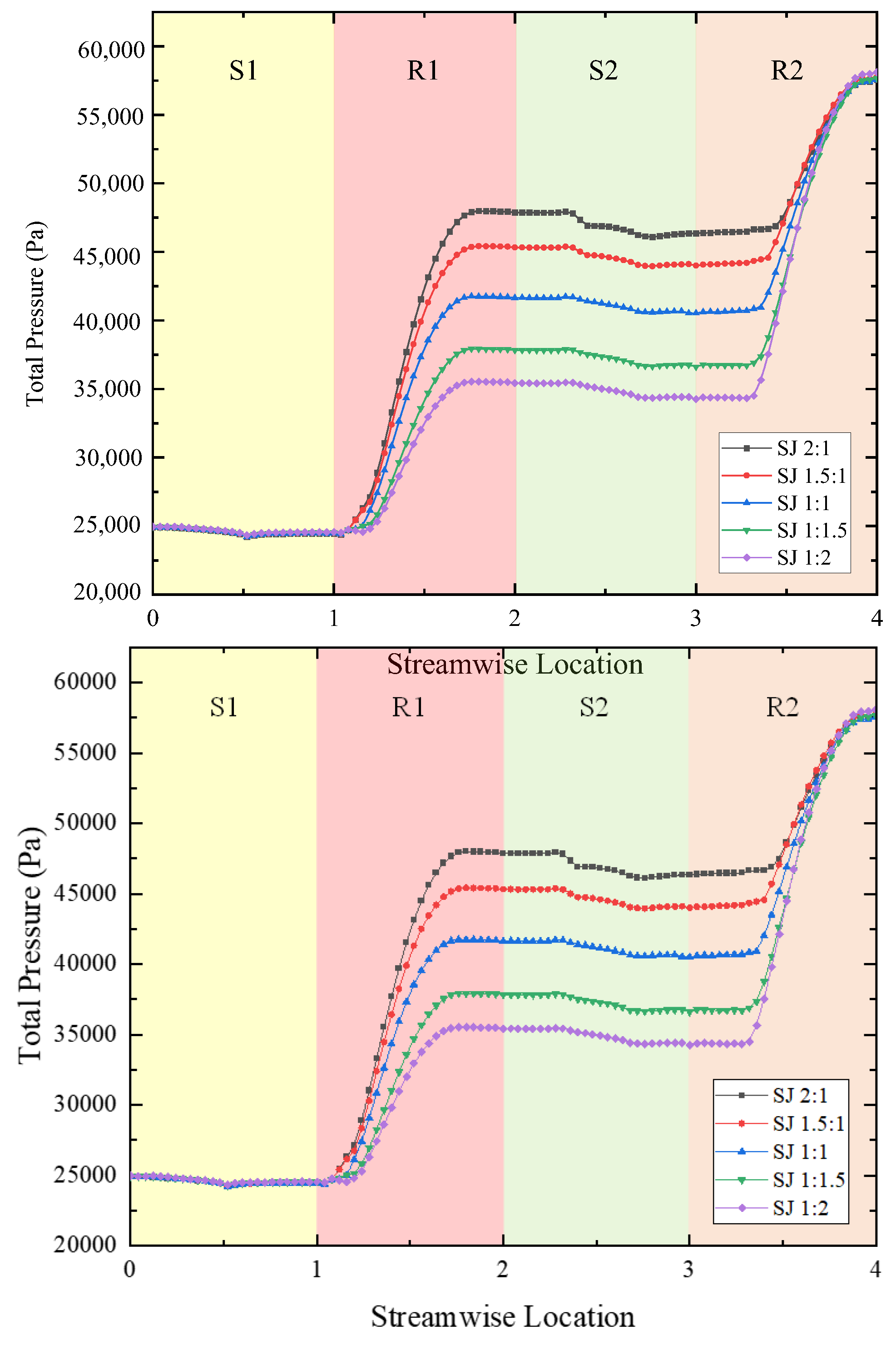
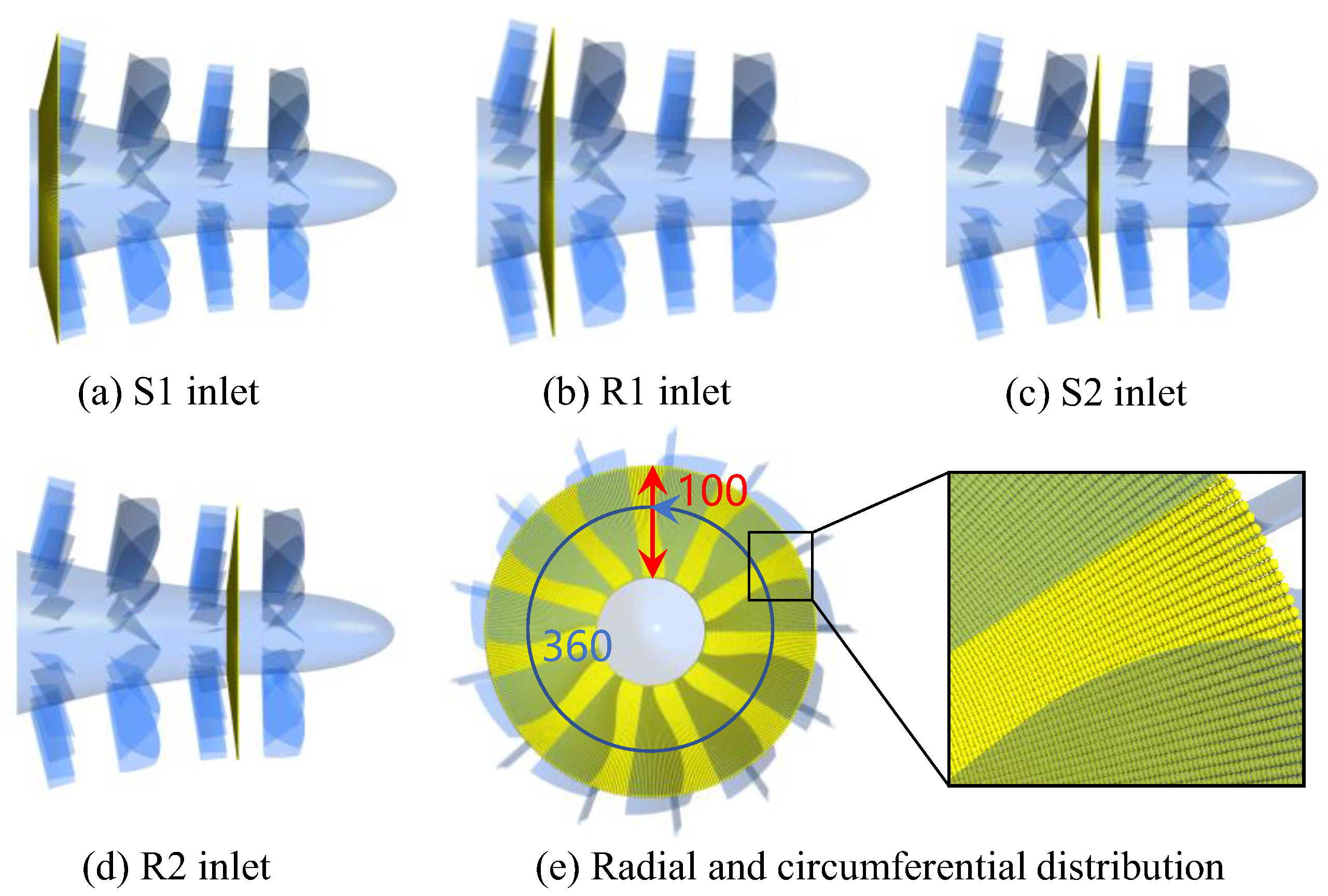
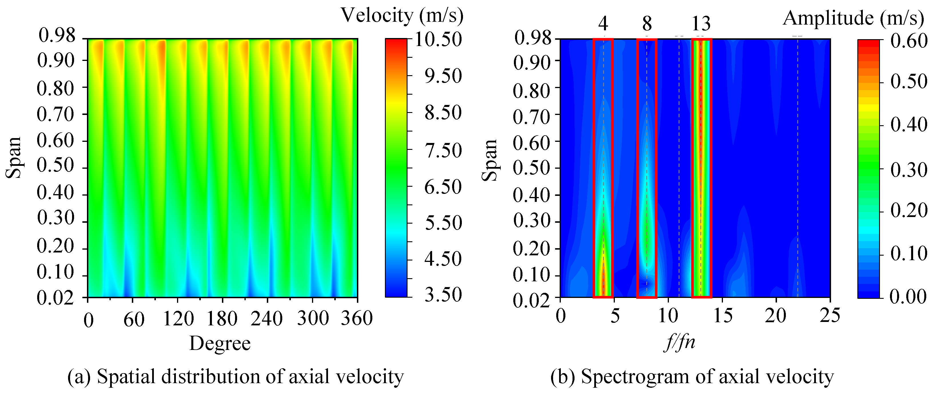
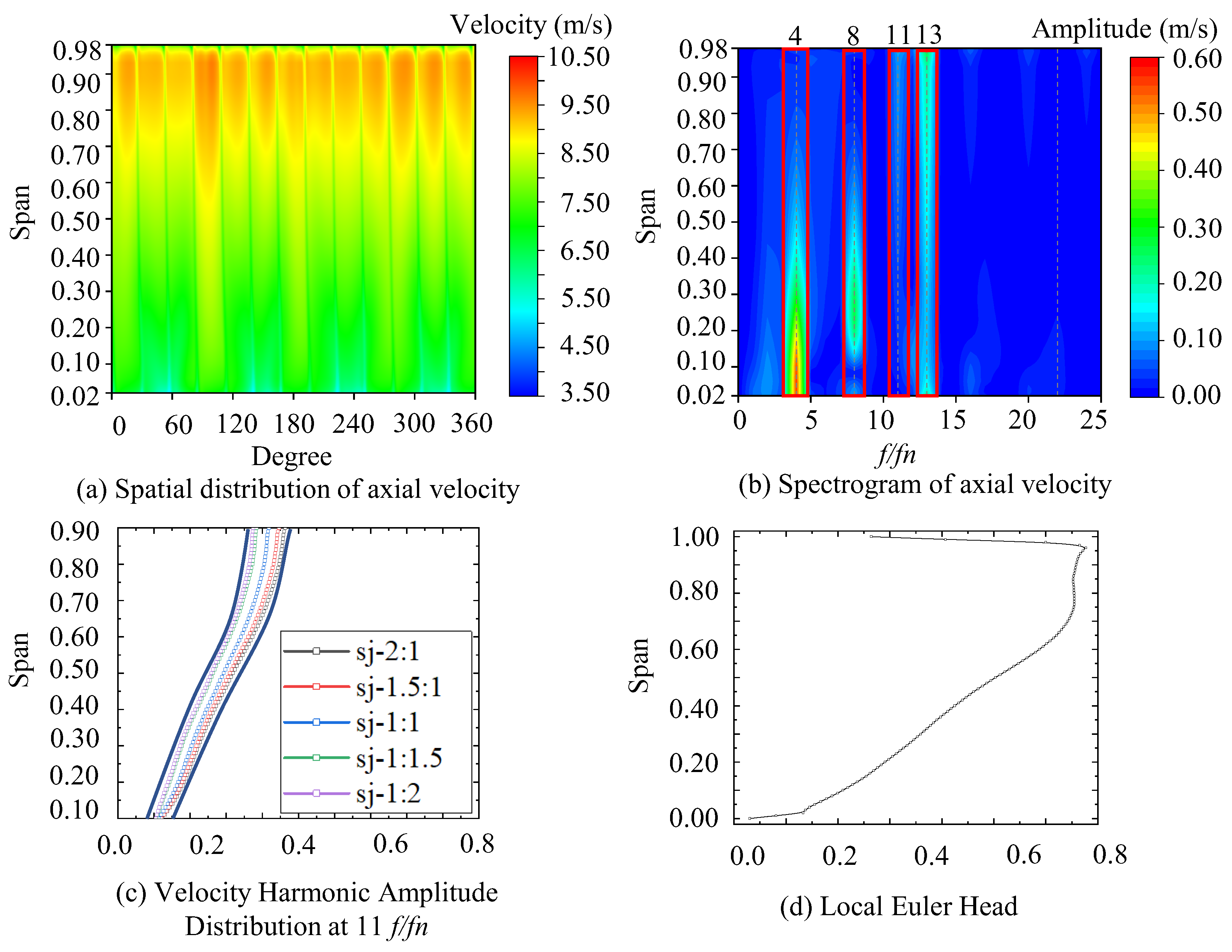
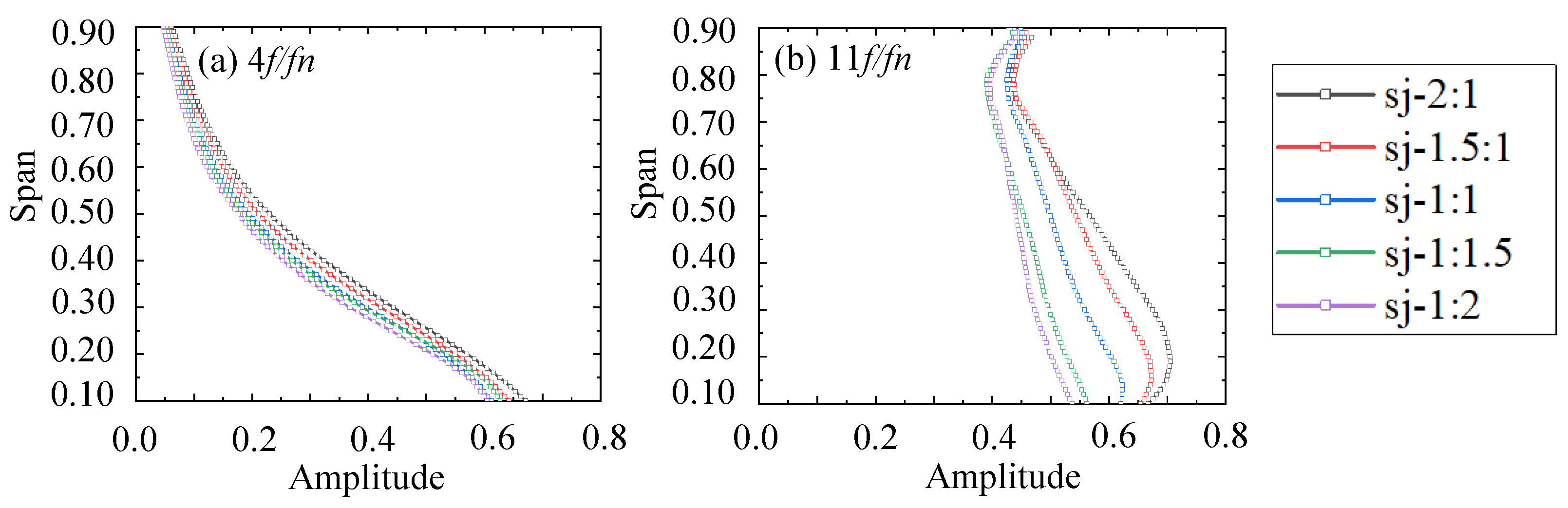
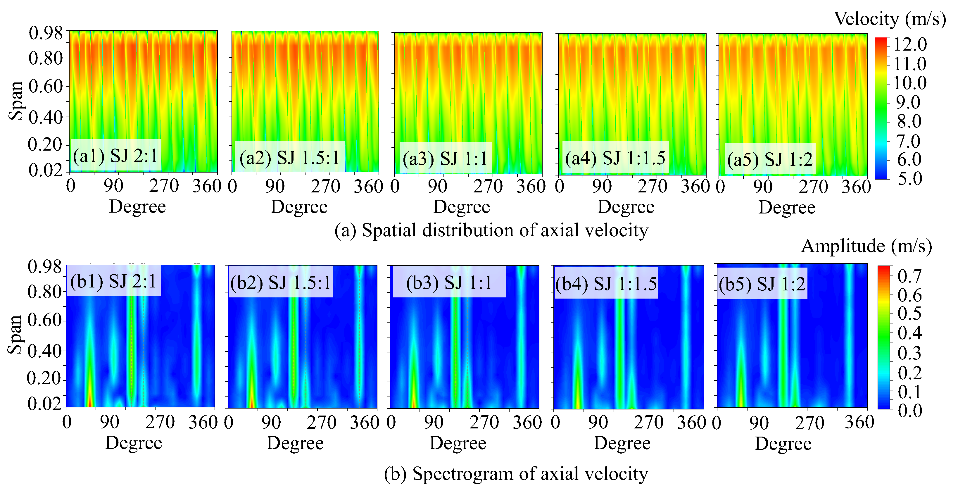
3.2. Spatio-Temporal Distribution of the Flow Field

The energy conversion of the propulsor is primarily driven by the rotation of the rotors. Due to differences in the actual flow field, the flow velocity can vary significantly, and the inflow conditions directly affect the load distribution on the rotor blades, thereby influencing the excitation force. The statistical analysis of the spatial distribution of the flow field in front of each propulsor component was conducted. The axial positions of the monitoring planes were set at the inlets of each component stage, with the four component sections named P1, P2, P3, and P4, respectively. Radially, 97 points were evenly distributed from span 0.02 to span 0.98 at intervals of span 0.01. Circumferentially, 360 points were evenly distributed from 1° to 360° at intervals of 1°. Therefore, each section contained a total of 34,920 points. The axial velocities at each section were extracted and analyzed. The layout of the monitoring planes and the positions of the monitoring points are shown in Figure 9.
First, the flow field at the inlet of the first-stage stator, referred to as P1, was analyzed. Since only the inlet and outlet angles of the first-stage rotor and the second-stage rotor were adjusted when designing the propulsor with different load distribution ratios, the inlet of the first-stage stator remained unchanged. Therefore, the flow field at the inlet of the first-stage stator is basically consistent under different load distribution ratios. Figure 10 shows the axial velocity distribution at the inlet of the first-stage stator and the spectral analysis, which involved performing a spatial Fast Fourier Transform (FFT) on each span to obtain the axial velocity spectrum. Spectral analysis can extract the spatial characteristics of each span. From the axial velocity spectrum, it can be observed that the axial velocity pulsations are mainly concentrated in the 4th, 8th, and 13th harmonic components. The fourth and eighth harmonic components are primarily concentrated at lower radii, with their influence being particularly significant below span 0.5. This indicates that the wake generated by the rudders has a more pronounced effect in the lower-radius region, leading to evident axial velocity pulsations. In contrast, the 13th harmonic component, influenced by the stator, has significant effects across the entire radial range, from low to high radii. This suggests that the interference effect associated with the stator blade number influences the 13th harmonic component throughout the span, resulting in a substantial pulsation amplitude at different radial positions.
As the flow progresses downstream, the axial velocity in front of the first-stage rotor shows an overall increase compared to that in front of the first-stage stator. This increase is mainly due to the work performed by the first-stage rotor, which reduces the low-speed region near the hub and expands the high-speed region at larger radii. In the axial velocity spectrum (Figure 11), it is evident that besides the pronounced pulsations at the 4th, 8th, and 13th harmonic components—similar to those in front of the first-stage stator—an 11th harmonic component also emerges in front of the first-stage rotor. This corresponds to the interference effect caused by the rotor blade count. These observations suggest that, as the flow develops downstream, the influence of the rotor on the axial velocity of the fluid progressively increases, whereas the stator’s influence diminishes. Notably, the influence of the fourth and eighth harmonic components is consistently concentrated below span 0.5, indicating a strong correlation with the low-radius region throughout the flow development.
Since the differences in the flow field contours among the five load distribution ratios are relatively minor, the 11th harmonic component was extracted for further quantitative analysis of the impact of load distribution ratios on specific harmonic components in the flow field, as shown in Figure 11c. To quantify the uniformity and stability of the flow field, the axial velocity harmonic component corresponding to the rotor blade count is defined as the Blade-Passing Frequency Velocity Harmonic Coefficient (BPFVHC). In this study, since the blade count was 11, the BPFVHC corresponded to the 11th harmonic component. For the BPFVHC, which is related to the rotor blade count, the harmonic amplitude showed an increasing trend as the radius grew. As the rotor load distribution ratio was aft-shifted, discrepancies in the BPFVHC gradually became more apparent, particularly from the hub to the shroud. The Euler head, which represents the ideal head generated by the rotor and indicates the work imparted to the fluid by the rotor blades, serves as an important parameter for evaluating the energy conversion efficiency of the impeller and can illustrate the rotor’s working capability at different radii to a certain extent. The extracted Euler head of the first-stage rotor, representing the work distribution of the impeller along the span, as shown in Figure 11d, reveals that the axial velocity pulsation magnitude along the span is in good agreement with the spanwise distribution of the Euler head. Both the Euler head and axial velocity pulsation amplitude exhibit lower values near the hub and increase progressively with the radius.
As the flow progresses downstream, the axial velocity distribution and its corresponding spectrum in front of the second-stage stator are depicted in Figure 12. Following the energy transfer from the first-stage rotor, the overall axial velocity in front of the second-stage stator further increases, and the flow non-uniformity also intensifies. It can be observed that as the load distribution ratio is gradually aft-shifted, the low-speed region at lower radii progressively diminishes, while the high-speed region at higher radii also decreases, resulting in a more uniform overall velocity distribution. This pattern, primarily shaped by the cumulative influence of upstream components, aligns with the design intention across the five models to ensure the load is aft-shifted. Consequently, the work performed by the first-stage rotor gradually decreases while the second-stage rotor’s workload increases, leading to a progressively more uniform flow field. From the axial velocity spectrum, it is evident that compared to the area in front of the first-stage rotor, the most notable change is the significant reduction in the 13th harmonic component associated with the stator blade count. Conversely, the BPFVHC corresponding to the rotor blade count and its multiples significantly increase, mainly due to the stronger influence of the rotor on the fluid as it approaches the rotor. As a result, the BPFVHC becomes the dominant factor in the flow field. Furthermore, at lower radii, the fourth harmonic component and its multiples, related to the rudder count, continue to exert a considerable influence.
To further analyze the specific flow field differences under the five load distribution ratios at position P3, the key fourth harmonic components and BPFVHC were extracted, as shown in Figure 13. It was observed that the overall distribution trend of the fourth harmonic component at P3 was similar to that at P2, gradually decreasing with the increasing span. However, the differences under various load distribution ratios were more pronounced than at P2, with the harmonic amplitude gradually decreasing as the load was aft-shifted. The distribution trend of the BPFVHC was similar to that of the fourth harmonic, both decreasing with an increasing span. However, compared to the fourth harmonic, the BPFVHC exhibited higher overall amplitudes, resulting in significant axial velocity pulsations across the entire span. As the load distribution ratio was aft-shifted, the BPFVHC also gradually decreased. Moreover, it was observed that the lower the radius, the greater the differences between the various load distribution ratios. This is because the absolute value of the axial velocity at low radii is relatively small, making it more susceptible to load changes. Therefore, it can be concluded that the smaller the amount of work performed by the first-stage rotor, the more uniform the flow field was at the tail outlet.
Figure 14a shows the axial velocity flow field distribution in front of the second-stage rotor (P4). Compared to P3, P4 exhibits an increase in axial velocity at both low and high radii. This is primarily because P4 is closer to the second-stage rotor, where the suction effect of the rotor is more pronounced. Comparing the flow fields under the five load distribution ratios at P4, a similar trend to P3 can be observed: the low-speed region at low radii gradually decreases as the load is aft-shifted, while the high-speed region at high radii also diminishes, resulting in a progressively uniform overall velocity distribution. Compared to the P3 section, observing the axial velocity spectrum at the P4 section in Figure 14b reveals that harmonic pulsations at low radii are more abundant, and due to the rectification effect of the stator, the 13th harmonic component associated with the stator blade count reappears.
Comparing the harmonic components of velocity pulsations under different load distribution ratios at the P4 section in Figure 15, it can be observed that for both the fourth harmonics and BPFVHC, the velocity pulsations gradually decrease and become more uniform as the rotor load distribution ratio is aft-shifted. In summary, as the rotor load distribution ratio is aft-shifted, both the absolute axial velocity and its harmonic pulsation amplitudes decrease progressively, resulting in a more uniform and orderly flow field in front of the second-stage rotor.
Based on the previous analysis of the spanwise flow field distribution at fixed axial positions for each component, cylindrical surfaces at spans of 0.2, 0.5, and 0.8 were selected as characteristic planes to further investigate the impact of load distribution ratios on the flow field along the flow direction. By extracting the axial velocity distribution at these positions and comparing the trends of axial velocity variation under different load distribution ratios, the regulatory effect of the load distribution ratios on the axial flow field characteristics was revealed. The generated axial velocity distribution data supplemented the spanwise flow field study and provided support for understanding the mechanisms by which load distribution ratios influence the flow field.
Figure 16 shows the axial velocity distribution at spans 0.2, 0.5, and 0.8 for the 1:2 and 2:1 load distribution ratio. Axial velocity generally increases along the flow direction through S1, R1, S2, and R2, reflecting the continuous energy transfer undertaken by both rotors. All models exhibit periodic flow patterns, indicating effective modulation by stators and rotors. Under the 2:1 ratio, a pronounced low-speed wake appears between R1 and S2 due to stronger rotor work and blade geometry near the hub. In contrast, the 1:2 model, with weaker R1 work and smaller exit angles, shows a more uniform flow near S2. In the R2 region, the 2:1 model’s rotor lacks sufficient load to overcome S2’s wake, while the 1:2 model enhances R2’s performance by expanding the high-speed suction region and improving flow uniformity. At span 0.5, the rotor outlet angle decreases, weakening flow separation and low-speed wakes. Despite some residual interference from upstream wakes, the 2:1 model’s stronger R2 effectively suppresses S2’s wake, improving downstream uniformity. At span 0.8, closer to the tip, overall velocity increases. Low-speed wakes persist, but the expanded suction-side high-speed zone in the 1:2 model more effectively suppresses S2’s wake than at lower spans. This highlights the significant benefit of rearward load redistribution, especially in tip regions.
In order to further observe how the velocity distribution on different span planes changes with load distribution ratios, local flow field regions near individual blades are displayed in detail. By combining the extracted vorticity distribution, the regulatory effect of load distribution ratios on the flow field can be more intuitively revealed. The display of local details highlights areas with large velocity gradients and the variation characteristics of the low-speed wake region, while the extraction of vorticity distribution effectively supplements the analysis of flow separation, wake strength, and turbulent regions. This helps to reveal the mechanism by which changes in load distribution ratios affect the flow field structure.
Figure 17 illustrates that as the load distribution is aft-shifted, the high-speed region on the suction surface of the mid-section of the second-stage rotor blades gradually expands, while changes in the pressure surface remain relatively insignificant. According to Bernoulli’s principle, the aft shift in the load distribution increases the flow velocity on the suction surface, leading to a further pressure reduction and an increased pressure difference between the suction and pressure surfaces. Since the thrust generated by the blades directly originates from the pressure difference between the suction and pressure surfaces, this trend indicates that the aft shift in the load leads to the greater thrust produced by the second-stage rotor. Observing the flow field distribution near the pressure surface at the leading edge of the blades reveals a distinct high-speed region, which gradually shrinks as the load distribution is aft-shifted. This phenomenon is primarily attributed to the reduced work of the first-stage rotor, resulting in a corresponding decrease in axial velocity entering the second-stage rotor. Under the condition of consistent rotational speed across different models, the circumferential velocity remains constant. According to the velocity triangle principle, the reduction in axial velocity alters the overall flow field velocity distribution, leading to the contraction of the high-speed region near the leading blade’s edge. This result indicates that changes in the load distribution ratio significantly affect the velocity distribution and energy transfer between the first- and second-stage rotors, as well as the internal flow field characteristics of the second-stage rotor.
Figure 18 presents the vorticity distribution characteristics on the span 0.8 cylindrical surface of the second-stage rotor under different load distribution ratios. The results indicate that high vorticity is primarily concentrated near the blade’s trailing edge, and as the load distribution ratio is aft-shifted, the vorticity intensity near the trailing edge shows a significant decreasing trend. A combined analysis with the velocity field distribution reveals that the range of the low-speed region near the trailing edge shrinks correspondingly, further highlighting the strong coupling relationship between local vorticity intensity and velocity distribution. Further analysis shows that in the SJ 2:1 model, a high-vorticity region nearly parallel to the blade appears in the flow passage, primarily caused by the extension and superposition of the second-stage stator wake effect into the rotor flow field. In contrast, for the SJ 1:2 model, the vorticity intensity at the same location significantly weakens, and the velocity field distribution shows that the low-speed region in this area almost completely disappears. This phenomenon primarily results from the aft shift in the load distribution, which increases the workload of the second-stage rotor, expands the high-speed region on the suction surface, and effectively covers and weakens the low-speed region induced by the stator wake. This finding demonstrates that aft-shifting the load distribution can significantly weaken the disturbance caused by the stator wake effect on the rotor flow field, improve the flow uniformity in the rotor region, and thereby optimize the flow field of the second-stage rotor.
Figure 19 presents the flow field and vorticity distribution characteristics on the span 0.25 cylindrical surface of the second-stage rotor near the hub. The overall distribution trend is similar to that at span 0.75, showing that the high-speed region on the suction surface expands as the load distribution ratio is aft-shifted, effectively covering the low-speed region induced by the stator wake drag. This phenomenon aligns closely with the changes in vorticity distribution, where the high-vorticity region in the flow passage gradually diminishes. However, since the span 0.25 region is closer to the hub, the blade’s setting angle is significantly larger compared to span 0.75. As the load distribution is aft-shifted, the low-speed region near the trailing edge gradually expands, while the high-vorticity region at the trailing edge also intensifies. This phenomenon highlights the importance of appropriately distributing the load ratio in dual-stage PJPs. While a moderate aft shift in the load can effectively optimize the flow field distribution, weaken the non-uniform disturbances caused by the stator wake effect, and improve the overall flow performance, an excessive aft shift may deteriorate the flow field due to the large blade setting angle. This can exacerbate flow separation near the trailing edge, increase vorticity intensity, and degrade the unsteady performance of the dual-stage propulsor. Therefore, controlling the load distribution ratio appropriately and avoiding excessive loading on the second-stage rotor is key to ensuring the stability and optimal unsteady performance of the dual-stage PJP.

3.3. Effect of Rotor Load Distribution on Unsteady Force

The unsteady force of the propulsor is a major source of vibration and noise for underwater vehicles, making its formation and suppression mechanisms significant in propulsor design. Since the rotor is the rotating component of the propulsor and contributes significantly to the unsteady force, this study primarily focuses on the tonal unsteady force of the rotor.
The unsteady calculations of the dual-stage PJP were conducted based on the steady-state results. The time step for the calculations was set to the time for the impeller to rotate by 1 deg. Data from six revolutions of the impeller, after achieving computational stability, were processed using FFT and other data processing methods.
Figure 20 presents the time domain diagram of the axial force for each component. It can be observed that, under the five different load distributions, the overall fluctuation trends of the axial forces for each component are quite consistent, differing only in mean values and the extent of fluctuations. As the energy distribution was aft-shifted, the mean F z , R 2 (Axial Force on the Second-Stage Rotor) gradually increased while the fluctuation range decreased. The mean F z , R 1 (Axial Force on the First-Stage Rotor) gradually decreased, and its fluctuation range also decreased. Similarly, the fluctuation ranges of F z , S 1 (Axial Force on the First-Stage Stator) and F z , S 2 (Axial Force on the Second-Stage Stator) also gradually decreased. Additionally, it is noteworthy in terms of frequency that R1, S2, and R2 all exhibited 22 peaks and troughs within one cycle, indicating that the second Blade-Passing Frequency (BPF) is the dominant frequency of axial force fluctuations. In summary, as the load was aft-shifted, the fluctuation range of the axial force gradually decreased.
To further quantify the variation pattern of unsteady forces with different load distribution ratios, a Fast Fourier Transform (FFT) was performed on the unsteady time domain curves of the dual-stage PJP, and the peaks of the frequency domain curves were extracted for comparison. Considering the significant changes in the absolute values of the thrust of the first- and second-stage rotors under different load distribution ratios and that the overall working capacity of the propulsor remained essentially consistent, the impact of load changes on the overall unsteady force fluctuations of the propulsor was investigated. The amplitude of the unsteady force for each component was divided by the total thrust of the two-stage rotors to obtain the ratio of the unsteady force of each component compared to the total thrust, as shown in Figure 21. Since the unsteady force peaks of different components occurred at different frequencies (1BPF, 2BPF), the larger value of the first- and second orders was selected for comparing the variation trend of the unsteady force for each component. It can be observed that as the load distribution ratio is aft-shifted, the unsteady force of each component decreases gradually.
To further intuitively capture the impact of changes in the load distribution ratio on the overall unsteady force of the propulsor, the time-domain signals of the first- and second-stage rotors were superimposed and subjected to a Fast Fourier Transform to obtain the unsteady force spectrum of the propulsor’s rotating components (Figure 22); it was found that the prototype’s unsteady force at a load distribution ratio of 1:1 was 0.69 N, and this decreased to 0.32 N at a load distribution ratio of 1:2 and a reduction of 53.6%. Compared to the model with a load distribution ratio of 2:1, the unsteady force of the model with a load distribution ratio of 1:2 decreased by 64.4%. In summary, as the load distribution ratio was aft-shifted, the overall unsteady force of the propulsor decreased continuously.
It can be observed that the primary reason for the reduction in the unsteady axial force of the propulsor as the load distribution ratio is aft-shifted is the simultaneous reduction in the unsteady forces of both the first- and second-stage rotors. However, it is generally expected that as the axial force of the rotor increases, the unsteady force also increases. In contrast, in the dual-stage PJPs, as the axial force of the second-stage rotor gradually increases, its unsteady axial force exhibits the opposite trend. The magnitude of the rotor’s unsteady force has been found to be closely related to its upstream flow field [39]. Therefore, by comparing the impact of load distribution changes on the flow field in Section 3.2, it can be concluded that aft-shifting the load distribution significantly reduces the BPFVHC in front of the second-stage rotor, leading to a more uniform flow field and markedly improved the inflow conditions at the front of the second-stage rotor. As a result, even though the aft shift in the load increases the absolute axial force of the second-stage rotor, its unsteady axial force continues to decrease. Therefore, in designing dual-stage PJPs, the load can be appropriately aft-shifted, allowing the second-stage rotor to bear more load and thus achieving low noise and low vibration design objectives. Additionally, this indicates that, given the consistent overall working capacity, the results of steady velocity distribution, particularly the BPFVHC, can predict the axial unsteady force. This lays a foundation for the rapid prediction of unsteady performance in future propulsors or axial flow fluid machinery design.

3.4. Effect of Rotor Load Distribution on Radiated Noise Characteristics

Underwater noise is generated by vibrations caused by excitation forces, which are transmitted to the water, resulting in sound waves. The noise level is closely related to changes in unsteady forces. Therefore, measuring radiated noise with a hydrophone is an effective method for studying the unsteady characteristics of PJPs. To verify the impact of load distribution ratios on the unsteady performance of the dual-stage PJPs, radiated noise tests were conducted on two dual-stage PJPs, SJ1:1 and SJ1:2, in the large-scale cavitation tunnel at the Shanghai Ship and Shipping Research Institute.
To analyze the noise measurement, we utilized the 8104 hydrophone from Denmark’s B&K, with a frequency response range of 0.1 Hz to 120 kHz. The noise signal was amplified and band-pass-filtered by a 2692A charge amplifier and then fed into B&K’s PULSE real-time noise analysis system for processing. To prevent interference from turbulent pressure pulsations on the hydrophone, the hydrophone was placed in a water tank outside the test section sidewall of the tunnel. The water tank was sealed to the tunnel’s plexiglass window, with the acoustic refraction coefficient of the plexiglass matching that of the water, thereby avoiding sound wave loss when passing through different media. The hydrophone’s vertical height matched the PJP’s shaft, and its longitudinal position aligned with the center of the duct.
As shown in Figure 23, the radiated noise spectrum consists mainly of line spectra and broadband noise, with energy concentrated between 10 Hz and 1 kHz. In addition to the blade frequency at 106.45 Hz, line spectra near 50 Hz and 300 Hz are also prominent. The 300 Hz line spectrum appeared in background noise tests of similar experiments conducted in this tunnel [40], suggesting that it occurs due to electromagnetic interference, while the 50 Hz line spectrum may be related to the frequency of shed vortices. Since the comparison was performed between the unsteady performance of propulsors with different load distribution ratios, only the sound pressure level (SPL) at the blade frequency (106.45 Hz) was compared. It can be observed that the sound pressure level at the blade frequency for SJ1:1 is 123.08 dB, while for SJ1:2, it is 116.41 dB, marking a reduction of 6.67 dB. This indicates that the load distribution ratio between the front and rear rotors affects the radiated noise of the pump jet, and this trend is consistent with the excitation force of the impellers.

4. Conclusions

This study employed validated numerical simulation and experimental methods to analyze the impact of different load distribution ratios between the front and rear rotors of dual-stage PJPs on the overall unsteady performance of propulsors. Using FFT, flow field spectrum analysis, and other methods, the following conclusions were obtained:
  • Different load distribution ratios have no significant impact on the propulsion performance of dual-stage PJPs. Whether the load is front-heavy and rear-light or front-light and rear-heavy, the propulsion efficiency differs by no more than 1% when the overall propulsion capability is consistent, with only slight differences in the work growth trend observed for first- and second-stage rotors;
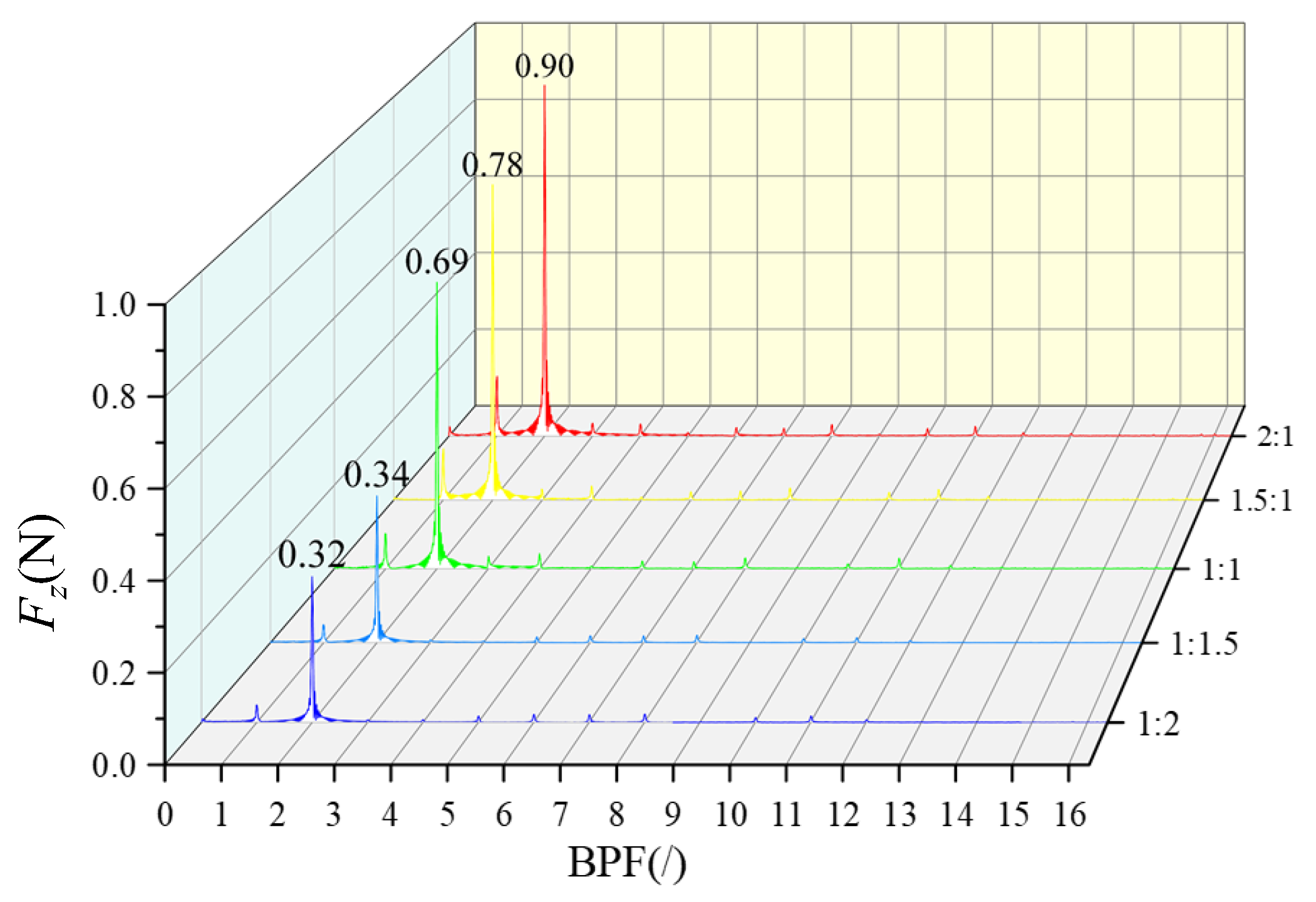
  • As the load distribution ratio is aft-shifted, the overall unsteady force of the propulsor decreases continuously. With a load distribution ratio of 1:1, the prototype unsteady force is 0.69 N; with a load distribution ratio of 1:2, the unsteady force decreases to 0.32 N, which is a reduction of 53.6%;
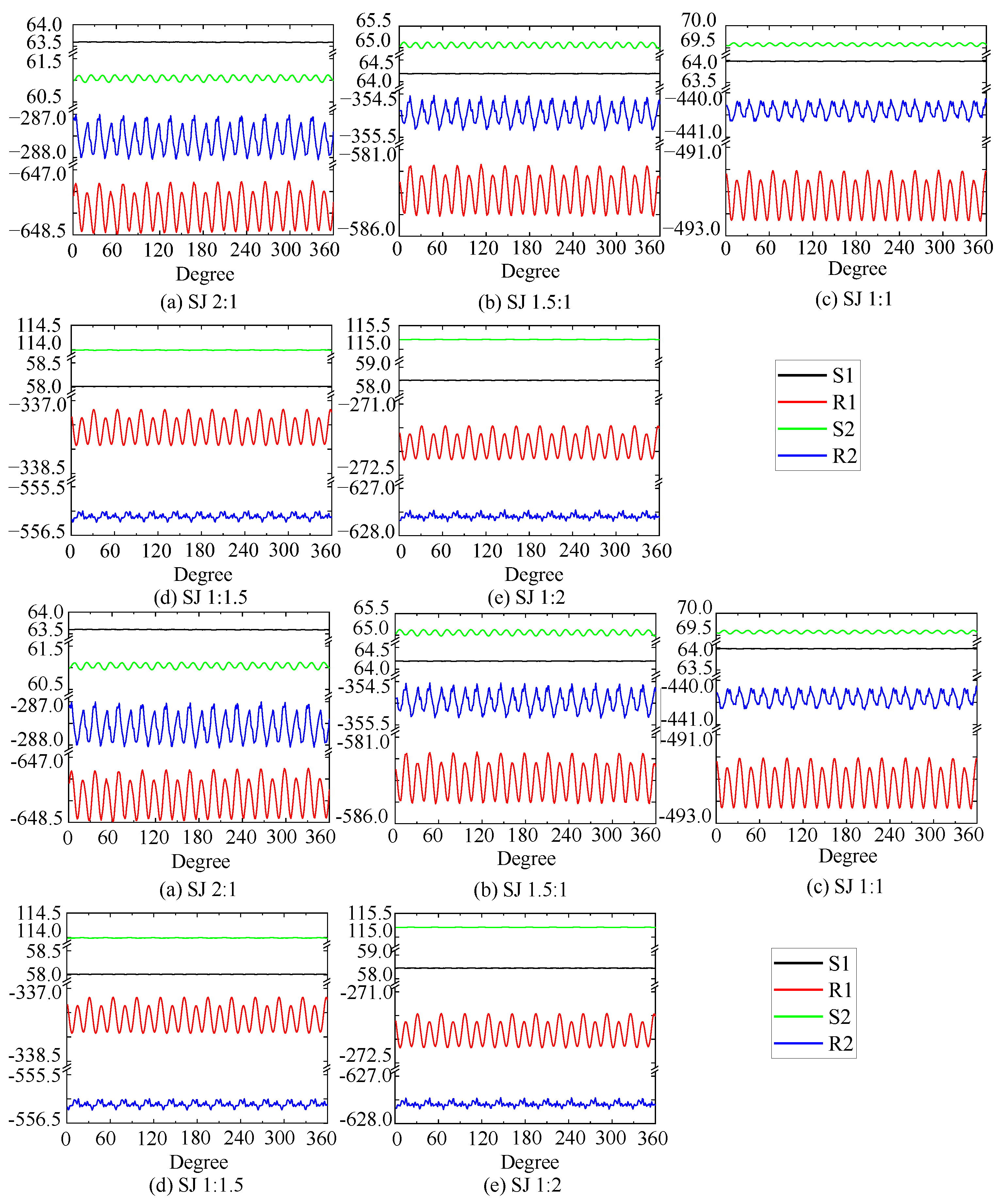
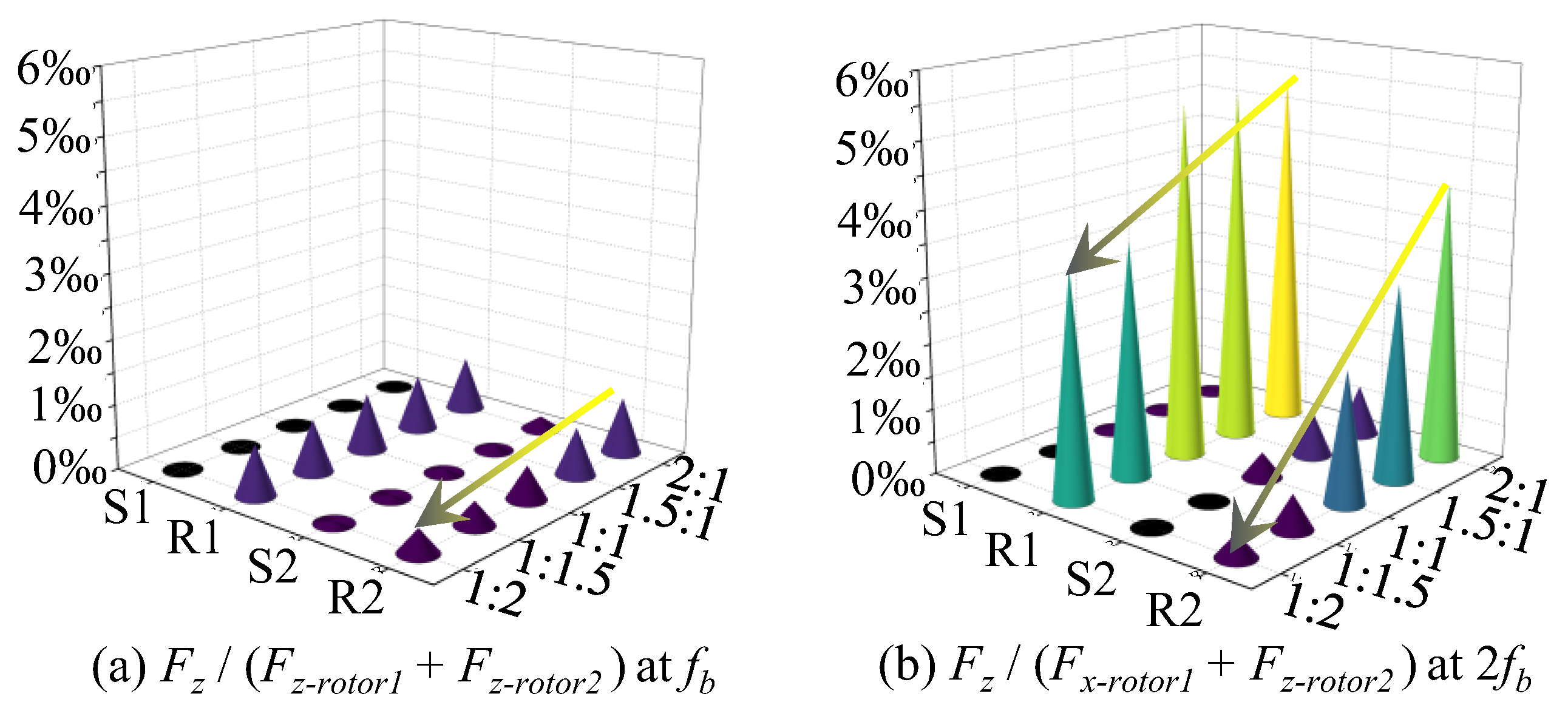
  • The principle behind the reduction in the unsteady axial force of the dual-stage PJPs with the aft shift in the load distribution ratio is the simultaneous decrease in the unsteady axial force of both the first- and second-stage rotors: the unsteady force of the first-stage rotor decreases due to the reduction in the axial force and unchanged inflow, while the decrease in the work performed by the first-stage rotor leads to a reduction in the BPFVHC, making the flow field more uniform and significantly improving the inflow conditions at the front of the second-stage rotor, thereby reducing its unsteady force;
  • The combined comparison of flow field spectrum analysis and unsteady force results under five different load distribution ratios can, to some extent, indicate that when the overall working capacity is consistent, the steady-state flow field distribution results, particularly for the BPFVHC, can predict axial unsteady force. This also lays a foundation for the rapid prediction of unsteady performance in future dual-stage PJPs or axial flow fluid machinery;
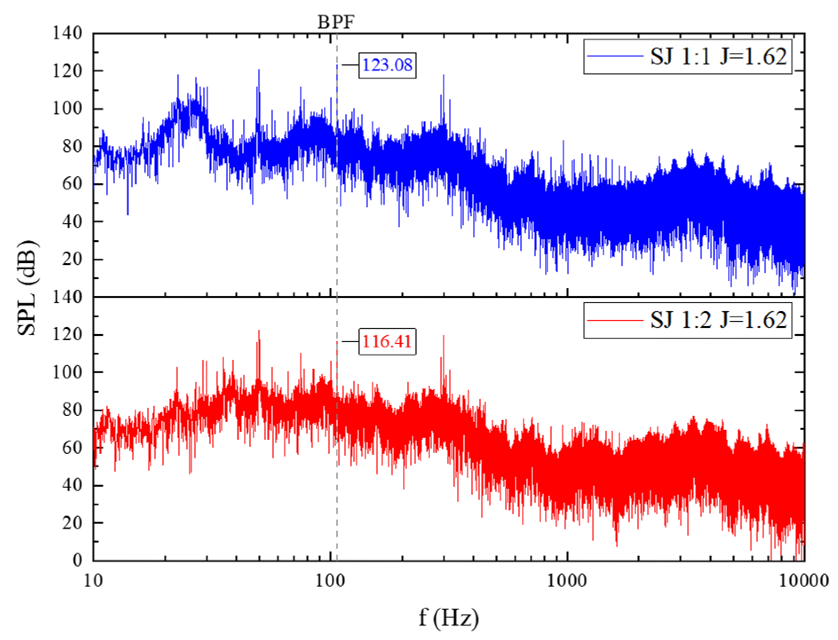
  • The sound pressure level results of radiated noise under different load distribution ratios are consistent with the excitation force results. The SJ1:2 pump-jet, compared to the SJ1:1 pump-jet, has a sound pressure level at blade frequency that is reduced by 6.67 dB. This indicates that aft shifting of the load distribution ratio is effective in reducing the unsteady performance of the dual-stage PJPs.
This study provides valuable guidance for the low-excitation design of dual-stage PJPs. During the study, the rotational speeds of both the first-stage and second-stage rotors were selected to ensure that the working points remained outside the cavitation regime, and no cavitation was observed in the corresponding experiments. Based on this research, the design method of reducing the first-stage rotor load and increasing the second-stage rotor load can significantly reduce the excitation force of the propulsor while maintaining almost unchanged propulsion performance, and it can also lower the sound pressure level of radiated noise. Therefore, this study is significant for low-excitation design.
It is important to note that the load distribution ratio is only one of the key parameters in the design of dual-stage pump-jet propulsors. Other influential factors—such as phase angles, blade count, and different rotor–stator blade array combinations—also play critical roles in determining unsteady excitation characteristics and overall performance. In this study, some of these aspects were simplified or kept constant to focus specifically on the effects of the load distribution. As a result, these findings are limited to the specific configuration investigated. Future work will explore multi-factor design approaches aimed at achieving low-excitation characteristics in dual-stage PJPs, which is expected to be a major focus and research hotspot. Nonetheless, the current study offers valuable design insights for the development of low-excitation dual-stage PJPs and other multi-stage rotating machinery.

Author Contributions

Conceptualization, J.Z. (Jiansheng Zhang), L.C., D.W. and N.L.; methodology, N.L. and L.C.; software, J.Z. (Jiansheng Zhang) and J.Z. (Jianwei Zhang); validation, J.Z. (Jiansheng Zhang) and H.H.; formal analysis, J.Z. (Jiansheng Zhang); investigation, J.Z. (Jiansheng Zhang) and W.Z.; resources, D.W.; data curation, J.Z. (Jiansheng Zhang); writing—original draft preparation, J.Z. (Jiansheng Zhang); writing—review and editing, L.C.; visualization, J.Z. (Jiansheng Zhang); supervision, L.C.; project administration, D.W.; funding acquisition, L.C. All authors have read and agreed to the published version of the manuscript.

Funding

This work was supported by the National Natural Science Foundation of China, grant number 52171326.

Data Availability Statement

The data presented in this paper are available upon contacting the corresponding author.

Acknowledgments

The authors would like to express their gratitude to Rui Wu, Heng Liu, and other staff members from the Shanghai Ship and Shipping Research Institute for their significant assistance during the experiments.

Conflicts of Interest

Authors Wei Zhao and Hanqiao Han were employed by the company Wuhan Second Ship Design and Research Institute. The remaining authors declare that the research was conducted in the absence of any commercial or financial relationships that could be construed as a potential conflict of interest.

Abbreviations

The following abbreviations are used in this manuscript:
CFDComputational Fluid Dynamics
SSTShear Stress Transport
PJPPump-jet propulsor
LsubLength of suboff
DsubDiameter of suboff
NS1Number of first-stage stator blades
NR1Number of first-stage rotor blades
NS2Number of second-stage stator blades
NR2Number of second-stage rotor blades
J Advance coefficient
K T Thrust coefficient
K Q Torque coefficient
η Propulsive efficiency
BPFBlade-passing frequency
FFTFast Fourier Transform
BPFVHCBlade-Passing Frequency Velocity Harmonic Coefficient
S1First-stage stator
R1First-stage rotor
S2Second-stage stator
R2Second-stage rotor
F x Vertical force
F y Lateral force
F z Axial force
F z , S 1 Axial force on the First-Stage stator
F z , R 1 Axial force on the First-Stage rotor
F z , S 1 Axial force on the Second-Stage stator
F z , R 2 Axial force on the Second-Stage rotor
fz,fb-R1Axial excitation force for the first blade-passing frequency of the first-stage rotor
fz,2fb-R1Axial excitation force for the second blade-passing frequency of the first-stage rotor

References

  1. Mccormick, B.W.; Elsenhuth, J.J. Design and performance of propellers and pumpjets for underwater propulsion. Aiaa J. 1963, 1, 2348–2354. [Google Scholar] [CrossRef]
  2. Ji, X.; Dong, X.; Yang, C. Attenuation of the tip-clearance flow in a pump-jet propulsor by thickening and raking the tips of rotor blades: A numerical study. Appl. Ocean. Res. 2021, 113, 102723. [Google Scholar] [CrossRef]
  3. Qiu, C.; Huang, Q.; Pan, G.; He, X. Multi-path deep learning framework on discrete pressure points to predict velocity field of pump-jet propulsor. Appl. Ocean. Res. 2022, 123, 103173. [Google Scholar] [CrossRef]
  4. Zhou, Y.K.; Pavesi, G.; Yuan, J.P.; Fu, Y.X.; Gao, Q.L. Effects of duct profile parameters on flow characteristics of pump-jet: A numerical analysis on accelerating and decelerating ducts distinguished by cambers and angles of attack. Ocean. Eng. 2023, 281, 114733. [Google Scholar] [CrossRef]
  5. Kim, J.W.; Kim, M.C.; Park, I.; Seol, H.; Kim, M.J.; Jin, W.S. Parametric study of the hydrodynamic characteristics of the pumpjet propulsor for the SUBOFF submarine. J. Mar. Sci. Eng. 2023, 11, 1926. [Google Scholar] [CrossRef]
  6. Hu, L. Study on Rotor-Rotor Interaction Contra and Hydraulic Optimal Design of Pump, Rotating Water-Jet. Master’s Thesis, Zhejiang University, Hangzhou, China, 2018. [Google Scholar]
  7. Furukawa, A.; Shigemitsu, T.; Watanabe, S. Performance test and flow measurement of contra-rotating axial flow pump. J. Therm. Sci. 2007, 16, 7–13. [Google Scholar] [CrossRef]
  8. Momosaki, S.; Usami, S.; Okuma, K.; Watanabe, S.; Furukawa, A. Experimental study on rotational speed control of contra-rotating axial flow pump. In Proceedings of the 3rd Asian Joint Workshop on Thermophysics and Fluid Science, Matsue, Japan, 10–14 September 2010; p. JP-02. [Google Scholar]
  9. Momosaki, S.; Usami, S.; Watanabe, S.; Furukawa, A. Numerical simulation of internal flow in a contra-rotating axial flow pump. IOP Conf. Ser. Earth Environ. Sci. 2010, 12, 12046. [Google Scholar] [CrossRef]
  10. Cao, L.; Watanabe, S.; Momosaki, S.; Imanishi, T.; Furukawa, A. Low Speed Design of Rear Rotor in Contra-Rotating Axial Flow Pump. Int. J. Fluid Mach. Syst. 2013, 6, 105–112. [Google Scholar] [CrossRef]
  11. Ross, D. Mechanics of Underwater Noise; Pergamon Press: Tarrytown, New York, USA, 1976. [Google Scholar]
  12. Merz, S.; Kinns, R.; Kessissoglou, N. Structural and acoustic responses of a submarine hull due to propeller forces. J. Sound. Vib. 2009, 325, 266–286. [Google Scholar] [CrossRef]
  13. Jessup, S.D. Measurement of Multiple Blade Rate Unsteady Propeller Forces; David Taylor Research Center: Bethesda, MD, USA, 1990. [Google Scholar]
  14. Tong, X.D.; Chen, H.Y.; Dong, X.Q.; Chen, Y. Experimental and numerical investigations on the unsteady thrust of a propeller in presence of an upstream rudder. Ocean. Eng. 2021, 237, 109644. [Google Scholar] [CrossRef]
  15. Yu, H.T.; Zhang, Z.G.; Hua, H.X. Numerical investigation of tip clearance effects on propulsion performance and pressure fluctuation of a pump-jet propulsor. Ocean. Eng. 2019, 192, 106500. [Google Scholar] [CrossRef]
  16. Yu, H.; Duan, N.; Hua, H.; Zhang, Z. Propulsion performance and unsteady forces of a pump-jet propulsor with different pre-swirl stator parameters. Appl. Ocean. Res. 2020, 100, 102184. [Google Scholar] [CrossRef]
  17. Li, H.; Huang, Q.; Pan, G.; Dong, X. The transient prediction of a pre-swirl stator pump-jet propulsor and a comparative study of hybrid RANS/LES simulations on the wake vortices. Ocean. Eng. 2020, 203, 107224. [Google Scholar] [CrossRef]
  18. Li, H.; Huang, Q.; Pan, G.; Dong, X.; Li, F. Effects of blade number on the propulsion and vortical structures of pre-swirl stator pump-jet propulsors. J. Mar. Sci. Eng. 2021, 9, 1406. [Google Scholar] [CrossRef]
  19. Yao, H.; Cao, L.; Wu, D.; Yu, F.; Huang, B. Generation and distribution of turbulence-induced forces on a propeller. Ocean. Eng. 2020, 206, 107255. [Google Scholar] [CrossRef]
  20. Yao, H.Y.; Cao, L.L.; Wu, D.Z.; Huang, B.; Qin, S.J.; Yu, F.X. Unsteady responses and correlation characteristics of propeller blades under turbulence excitation. Ocean. Eng. 2022, 266, 112631. [Google Scholar] [CrossRef]
  21. Zhang, Y.; Han, J.T.; Huang, B.; Zhang, D.H.; Wu, D.Z. Control method of line spectrum excitation force for pump-jet propeller: Random unevenly spaced rotor blades. Phys. Fluids 2023, 35, 097104. [Google Scholar] [CrossRef]
  22. Zhang, Y.; Han, J.T.; Huang, B.; Zhang, D.H.; Wu, D.Z. Excitation force on a pump-jet propeller: The effect of the blade number. Ocean. Eng. 2023, 281, 114727. [Google Scholar] [CrossRef]
  23. Zhang, Y.; Han, J.T.; Huang, B.; Zhang, D.H.; Wu, D.Z. Suppression method for exciting force of pump jet propellers based on sinusoidal unevenly spaced rotor blades. Ocean. Eng. 2022, 262, 112198. [Google Scholar] [CrossRef]
  24. Li, H.; Huang, Q.G.; Pan, G.; Dong, X.G.; Xu, L.H. Study on the thrust fluctuation and vortices of a pump-jet propulsor under different duct. Ocean. Eng. 2023, 271, 113788. [Google Scholar] [CrossRef]
  25. Li, S.Z.; Li, F.Z.; Huang, Q.G.; Pan, G.; Wang, S.X.; Tian, X.S. On the space-time decomposition and reconstruction of the pump-jet propulsor flow field. Ocean. Eng. 2023, 286, 115521. [Google Scholar] [CrossRef]
  26. Li, F.Z.; Huang, Q.G.; Sun, G.C.; Pan, G.; Li, H.; Bai, C.A. Numerical simulation of the flow field and radiation noise from a pump-jet propulsor under various stator pre-whirl angles. Appl. Ocean. Res. 2023, 135, 103558. [Google Scholar] [CrossRef]
  27. Fujun, W. Research Progress of Computational Model for Rotating Turbulent Flow in Fluid Machinery. Trans. Chin. Soc. Agric. Mach. 2016, 47, 1–14. [Google Scholar]
  28. Tian, C. Research on the Influence of the Wake Field of Underwater Vehicles on Propulsor Exciting Force Characteristics; Zhejiang University: Hangzhou, China, 2022. [Google Scholar]
  29. Qin, D.; Pan, G.; Lee, S.; Huang, Q.; Shi, Y. Underwater radiated noise reduction technology using sawtooth duct for pumpjet propulsor. Ocean. Eng. 2019, 188, 106228. [Google Scholar] [CrossRef]
  30. Li, F.Z.; Liu, G.S.; Huang, Q.G.; Sun, G.C.; Pan, G.; Qin, D.H. Influence of asymmetric pre-whirl stator spacing on unsteady characteristics of pump-jet propulsor. Ocean. Eng. 2023, 273, 113896. [Google Scholar] [CrossRef]
  31. Huang, X.C.; Shi, S.K.; Su, Z.W.; Tang, W.H.; Hua, H.X. Reducing underwater radiated noise of a SUBOFF model propelled by a pump-jet without tip clearance: Numerical simulation. Ocean. Eng. 2022, 243, 110277. [Google Scholar] [CrossRef]
  32. Zou, D.L.; Lv, F.R.; Ta, N.; Rao, Z.S. Study on bearing force of marine propeller induced by longitudinal vibration of propulsion-shafting. Ships Offshore Struct. 2020, 15, 162–173. [Google Scholar] [CrossRef]
  33. Zou, D.L.; Jiao, C.X.; Ta, N.; Rao, Z.S. Theoretical study on the axial excitation force transmission characteristics of marine propellers. Ocean. Eng. 2019, 189, 106364. [Google Scholar] [CrossRef]
  34. Shi, S.K.; Tang, W.H.; Huang, X.C.; Dong, X.Q.; Hua, H.X. Experimental and numerical investigations on the flow-induced vibration and acoustic radiation of a pump-jet propulsor model in a water tunnel. Ocean. Eng. 2022, 258, 2022258. [Google Scholar] [CrossRef]
  35. Menter, F.R. 2-equation eddy-viscosity turbulence models for engineering applications. Aiaa J. 1994, 32, 1598–1605. [Google Scholar] [CrossRef]
  36. Yang, J.; Feng, D.K.; Liu, L.W.; Wang, X.Z.; Yao, C.B. Research on the Performance of Pumpjet Propulsor of Different Scales. J. Mar. Sci. Eng. 2022, 10, 78. [Google Scholar] [CrossRef]
  37. Menter, F.R.; Kuntz, M.; Langtry, R. Ten years of industrial experience with the SST turbulence model. In Reviews in Turbulence, Heat and Mass Transfer; Springer: Berlin/Heidelberg, Germany, 2003; Volume 4. [Google Scholar]
  38. Liu, H. Summary of DARPA Suboff Experimental Program Data; Naval Surface Warfare Center, Carderock Division (NEWCCD): Bethesda, MD, USA, 1998. [Google Scholar]
  39. Zhang, J.; Cao, L.; Cui, J.; Ren, H.; Wang, Y.; Wu, D. Effects of non-uniform inflow on the spatial and temporal distribution of impeller excitation in axial flow pumps in water tunnels. J. Mech. Sci. Technol. 2023, 37, 5251–5262. [Google Scholar]
  40. Li, Q. Research on Acoustic Characteristics Analysis and Characteristic Line Spectrum Extraction Method of Propulsion Pump Noise; Zhejiang University: Hangzhou, China, 2021. [Google Scholar]
Figure 1. Suboff and SJ 1:1 models.
Jmse 13 00726 g001
Figure 2. Computational domain and boundary conditions.
Jmse 13 00726 g002
Figure 3. Computational domain mesh.
Jmse 13 00726 g003
Figure 4. Decay process of residuals of steady-state simulations.
Jmse 13 00726 g004
Figure 5. y+ Distribution on the surface of the suboff.
Jmse 13 00726 g005
Figure 6. Experimental setup of dual-stage PJP.
Jmse 13 00726 g006
Figure 7. Verification of the aft propulsion performance of the dual-stage PJP SJ1:1.
Jmse 13 00726 g007
Figure 8. Total Pressure Increase Process of dual-stage PJP.
Jmse 13 00726 g008
Figure 9. Axial and circumferential position distribution of monitoring points.
Jmse 13 00726 g009
Figure 10. Axial velocity at the inlet of the first-stage stator (P1).
Jmse 13 00726 g010
Figure 11. Axial velocity at the inlet of the first-stage rotor (P2).
Jmse 13 00726 g011
Figure 12. Axial velocity distribution at the inlet of the second-stage stator (P3).
Jmse 13 00726 g012
Figure 13. Key harmonic component distribution of axial velocity at the inlet of the second-stage stator: (a) 4th; (b) 11th.
Jmse 13 00726 g013
Figure 14. Axial velocity distribution at the inlet of the second-stage rotor.
Jmse 13 00726 g014
Figure 15. Key harmonic component distribution of axial velocity at the inlet of the second-stage rotor: (a) 4th; (b) 11th.
Jmse 13 00726 g015
Figure 16. Axial velocity distribution of the two-stage PJP: (a) span 0.2; (b) span 0.5; and (c) span 0.8.
Jmse 13 00726 g016
Figure 17. Axial velocity distribution of the second-stage rotor at span 0.8.
Jmse 13 00726 g017
Figure 18. Vorticity distribution of the second-stage rotor at span 0.8.
Jmse 13 00726 g018
Figure 19. Velocity and vorticity distribution of the second-stage rotor at span 0.2.
Jmse 13 00726 g019
Figure 20. Time domain curve of unsteady axial force of dual-stage PJP.
Jmse 13 00726 g020
Figure 21. Ratio of unsteady blade force to total rotor thrust for each component of the dual-stage PJP.
Jmse 13 00726 g021
Figure 22. Spectrum of unsteady rotor force of dual-stage PJP.
Jmse 13 00726 g022
Figure 23. Radiated noise spectrum of SJ1:1 and SJ1:2.
Jmse 13 00726 g023
Table 1. Main parameters for SJ 1:1.
ComponentsParametersValue
DuctDiameter (mm)232
First-stage statorNumber of first-stage stator blades, NS1 (/)13
First-stage rotorNumber of first-stage rotor blades, NR1 (/)11
Hub-to-diameter ratio (/)0.42
Tip clearance (mm)0.5
Direction of rotationCounterclockwise
Second-stage statorNumber of second-stage stator blades, NS2 (/)13
Second-stage rotorNumber of second-stage rotor blades, NR2 (/)11
Hub-to-diameter ratio (/)0.33
Tip clearance (mm)0.5
Direction of rotationCounterclockwise
Table 2. Blade outlet angle for each model.
Components (deg)SJ 2:1SJ 1.5:1SJ 1:1SJ 1:1.5SJ 1:2
First-stage stator68.0068.0068.0068.0068.00
First-stage rotor45.3743.3741.7240.9840.59
Second-stage stator72.0072.0072.0072.0072.00
Second-stage rotor42.5043.2544.6145.0146.25
Table 3. Effect of mesh number on suboff drag (V = 18 knots; reference drag: 846.23 N).
Number of Mesh Cells (Million)Drag (N)Deviation (/)
Mesh 14.33841.040.61%
Mesh 27.45842.530.44%
Mesh 313.19842.940.39%
Table 4. Effect of time step on the transient performance of the propulsor (V = 18 kn).
Rotor Rotation Angle(deg)fz,fb-R1 (N)/Fluctuation Range (/)fz,2fb-R1 (N)/Fluctuation Range (/)fz,fb-R2 (N)/Fluctuation Range (/)fz,2fb-R2 (N)/Fluctuation Range (/)
20.101/19%0.386/23%0.029/40%0.048/74%
10.082/36%0.503/10%0.048/39%0.187/38%
0.50.128/-0.561/-0.079/-0.304/-
Table 5. Hydrodynamic performance of each dual-stage PJP model.
SJ 2:1SJ 1.5:1SJ 1:1SJ 1:1.5SJ 1:2
Head (m)3.353.383.363.403.45
Propulsive efficiency (/)80.14%80.76%80.84%80.50%79.91%
First-stage rotor torque (Nm)48.8443.9636.7129.1924.69
Second-stage rotor torque (Nm)24.7029.6535.9644.1749.92
First-stage rotor thrust (N)636.47575.85486.30369.16307.24
Second-stage rotor thrust (N)301.27364.83443.66567.29633.57
First-stage rotor head (m)2.472.201.801.391.14
Second-stage rotor head (m)1.131.401.752.202.50
Torque ratio (/)1.981.481.020.660.49
Thrust ratio (/)2.111.581.100.650.48
Head ratio (/)2.201.571.030.640.45
Disclaimer/Publisher’s Note: The statements, opinions and data contained in all publications are solely those of the individual author(s) and contributor(s) and not of MDPI and/or the editor(s). MDPI and/or the editor(s) disclaim responsibility for any injury to people or property resulting from any ideas, methods, instructions or products referred to in the content.

