Abstract
Critical to evaluating the economic viability of a wave energy project is: (1) a robust estimate of the electricity production throughout the project lifetime and (2) an understanding of the uncertainty associated with said estimate. Standardization efforts have established mean annual energy production (MAEP) as the metric for quantification of wave energy converter (WEC) electricity production and the performance matrix approach as the appropriate method for calculation. General acceptance of a method for calculating the MAEP uncertainty has not yet been achieved. Several authors have proposed methods based on the standard engineering approach to error propagation, however, a lack of available WEC deployment data has restricted testing of these methods. In this work the magnitude and sensitivity of MAEP uncertainty is investigated. The analysis is driven by data from simulated deployments of 2 WECs of different operating principle at 4 different locations. A Monte Carlo simulation approach is proposed for calculating the variability of MAEP estimates and is used to explore the sensitivity of the calculation. The uncertainty of MAEP ranged from 2%–20% of the mean value. Of the contributing uncertainties studied, the variability in the wave climate was found responsible for most of the uncertainty in MAEP. Uncertainty in MAEP differs considerably between WEC types and between deployment locations and is sensitive to the length of the input data-sets. This implies that if a certain maximum level of uncertainty in MAEP is targeted, the minimum required lengths of the input data-sets will be different for every WEC-location combination.
1. Introduction
Assessing the electricity output of a wave energy converter (WEC) throughout the project lifetime is critical to evaluating the economic viability of a wave energy project. Mean annual energy production (MAEP), a WEC’s annual energy production averaged over sufficient duration to account for variations in wave climate, is a key metric used for such assessments. However, MAEP alone is insufficient for clarifying the viability of WEC projects. To gain a financial foothold, the risks associated with the WEC under-producing need quantification, and thus quantification of the uncertainty in the MAEP is also necessary.
In typical practice, WEC power production is characterized over discretized ranges of the met-ocean parameters significant wave height () and energy period () forming what is known as the performance matrix. A current challenge to the wave energy sector is generating equitable and standardized methods for assessing the performance of WEC technologies. One stream of this effort is in the development of technical specifications through the International Electrotechnical Commission. IEC/TS-62600-100ed1.0, 2012 [1] provides guidance on power performance assessment, specifically on the formulation of a performance matrix and MAEP calculations, based on measured data from a deployed WEC at a single location.
However, when applying the aforementioned methods to calculations of the deployed WEC’s MAEP, uncertainties arise from a variety of contributing factors and there is currently no accepted method for quantifying the uncertainty in MAEP calculations.
Addressing this problem requires a propagation of uncertainty from both the WEC deployment data and the historic met-ocean data. Following through with such an uncertainty analysis requires access to data from WEC deployments of sufficient duration and quality. Several WECs have undergone full or near-full scale sea trials, however the deployment have typically been less than a year and business interests of the proponent company usually preclude distribution of the data. One notable exception is Wave Star Energy who have released data from their sea trials at Hanstholm, Denmark [2]. However, even the Wave Star data is not of sufficient fidelity or duration to enable a thorough uncertainty analysis.
Thus, this work has two main aims: (1) to generate WEC power production data of sufficient duration and quality to afford an uncertainty analysis; and (2) to analyze the WEC power data in a way that quantifies the key contributing factors to the MAEP uncertainty arising from the performance matrix approach.
2. Background
Capture length, also known as “capture width”, is the established measure of the efficiency for WECs [3]. Capture length is defined from the average WEC power output (P) and the wave power transport (J), as follows:
WEC performance is characterized from data collected during operation in real seas. For performance characterization it is important that P is recorded, along with a measurement of the wave spectrum for each quasi-static period of operation (typically 20 min to 3 h). From the wave spectrum, parameters , , and J can be calculated. These wave parameters are related by:
where is the group velocity associated with .
The performance of the WEC is characterized by allocating the parametric data-set into bins, typically forming a bi-variate histogram1 with dimensions , and .
From the histogram, the ith bin represents one combination of the total N possible combinations defined by the chosen histogram bin boundaries. is the frequency of occurrence of ith bin such that , is the average wave power transport of all records in the ith bin, and is average capture length of all records in the ith bin. The matrix is known as the performance matrix.
Two different data-sets are used for the calculation of the average capture length, wave power transport, and frequency of occurrence matrices (, , ).
- The WEC deployment data-set consists of data collected during a WEC deployment. It is used to calculate the matrix.
- The historic met-ocean data-set is a long-term (10+ year) parametric wave data-set representative of the WEC deployment location. It is used to calculate the and matrices.
Even a multi-year WEC deployment is insufficient to capture the variability of the local wave climate. The much longer historic met-ocean data-set provides a better representation of the local climate variability, so is more appropriate for the calculation of the and matrices.
Finally, the MAEP at the deployment location can be calculated by Equation (3) where 8766 is the average number of hours per year [1].
3. Literature Review
Livermore [4] presents a method of MAEP uncertainty analysis based on standard error propagation, similar to that used in the wind energy industry. He breaks down the sources of MAEP uncertainty into four categories:
- Measurement uncertainty derives from the inherent limitations of the wave measurement instrument (WMI).
- Temporal extrapolation uncertainty derives from using a limited duration data-set to estimate conditions over a much longer period.
- Spatial extrapolation uncertainty derives from any methods used to transfer wave data to the location of the WEC (such as a wave propagation model).
- Device performance uncertainty derives from the limitations and assumptions used in the performance characterization methodology.
Items 1 to 3 apply to the historic met-ocean data-set. Item 4 applies to the WEC deployment data-set, but may include items 1 to 3. Livermore further seperates uncertainty into a number of sub-categories; these are provided in Table 1.

Table 1.
Categorization of uncertainty in mean annual energy production estimates for wave energy converters [4].
Livermore notes that the standard approach relies on two significant assumptions:
- that the individual errors are uncorrelated and can be approximated as normal distributions.
- that the central limit theorem is applicable to multiplication of uncertain variables as well as addition (which is only valid for small uncertainty levels).
He further notes that though challenging to apply, an alternative approach based on Monte Carlo simulation would not necessarily be subject to the above assumptions.
Guanche et al. [5] used a boot-strap re-sampling technique to investigate the sensitivity of a number of economic metrics to the variability in the wave climate (i.e., temporal extrapolation uncertainty). They found significant variability in these financial metrics due to variability of the wave climate. A qualitative recommendation is made for the use of a long met-ocean data-set in these calculations. They do not investigate the impact of uncertainty originating from the WEC performance characterization.
Mackay et al. [6,7] investigate the impact of sampling variability on WEC performance uncertainty. Sampling variability stems from the fact that a sample of finite length must be used to estimate the underlying wave spectrum. Because that sample represents only one realization of the underlying wave spectrum, it is expected that the sample will vary from the real spectrum (which would require an infinitely long sample to calculate). Where two samples are collected a short distance from one another, the expected variation between the samples depends on the distance between them and the wave heading. Livermore [4] does not directly address sampling variability, but it may be considered to fall into any of his 4 categories. Mackay et al. found that inclusion of sampling variability increased the intra-bin variability in L 10%–50% depending on the region of the matrix. They did not investigate how this variability translated to uncertainty in MAEP.
Kofoed et al. [8,9] provides a method for estimating the uncertainty in MAEP associated with device performance uncertainty, including for situations of limited data. The authors use standard methods for error propagation similar to Livermore and the authors mention that Monte Carlo simulation may be a more robust alternative. These works focus on the uncertainty of the performance matrix and do not consider the uncertainty in MAEP associated with historic met-ocean data-set.
Bailey et al. [10] use a numerical model of a self-reacting point absorber within a Monte Carlo simulation to investigate the variability in WEC power production within single - bin (device performance uncertainty). For their experiment they found a standard deviation in power production which is 26% of the mean and conclude that this variability is mostly due to variability in wave conditions within the bin. They did not investigate the impact of this variation on MAEP.
In this work we use a Monte Carlo approach to calculate the uncertainty in MAEP estimates and attempt to account for as many of the contributing uncertainties as possible. With this approach we aim to highlight the relative importance of each uncertainty source previously studied and provide a base-line estimate for the total uncertainty associated with the standard matrix approach for MAEP calculation.
4. Methods
This research is conducted in two phases. First, to address the lack of WEC performance data, several long-term WEC deployments were simulated using high fidelity time-domain numerical models. Second, we use the data from each WEC deployment, along with the associated met-ocean data to estimate the MAEP and conduct an assessment of the associated uncertainty.
4.1. Site Selection
Four Locations were selected for simulated WEC deployments. Within each location two sites have been identified: one at 45 m or greater water depth (referred to as ‘off-shore’) and another at approximately 25 m of water depth (referred to as ‘near-shore’). See Table 2 for location names, coordinates and depths.

Table 2.
Reanalysis wave data sources.
These locations have different climate dynamics and prevailing met-ocean conditions. In general Canadian Pacific and UK Atlantic locations are both subjected to strong swell while the Canadian Atlantic and UK North Sea locations are subjected to a combination of swell and local wind seas.
4.2. Wave Data Sources
Wave data was sourced from hind-cast and reanalysis models as fully directional wave spectra. The use of re-analysis data provided complete data-sets, unbiased by data intermittent typical of in-situ measurements. Sources for the wave data used at each location and site are provided in Table 2. The UK sources have 36 years of data available, while the Canadian sources have 10 years available.
4.3. Wave Data Analysis
The wave data, as collected from the different sources, were initially wave spectra defined in different frequency resolution and unit conventions. As a consequence, the met-ocean data was pre-processed to ensure consistency in frequency resolution and measurement units. This process was important because some wave parameters, such as spectral band-width, are known to be sensitive to the frequency resolution [15,16]. After processing, the frequency discretization ranges from 0.004 to 0.4775 Hz at constant 0.004 Hz bin-width. The direction discretization ranges from 0 to 359° at 15° bin-width.
From the spectra, all wave parameters recommended by IEC/TS-62600-101ed1.0 wave resource assessment technical specification were calculated.
4.4. WEC Simulations
Two WECs with different dynamic characteristics were selected for simulation. These two WECs were chosen for their different absorption principles and power matrix characteristics. The first WEC is a two-body self reacting point absorber (SRPA) and the second WEC is a pitching flap also known as an oscillating wave surge converter (OWSC). The point absorber’s dynamics and power production are known to be reasonably independent of wave direction, but more sensitive to spectral band-width; the pitching flap WEC’s dynamics and power production are known to strongly depend on the incident wave direction, but is less sensitive to spectral shape. Each of the two WECs are evaluated at all four aforementioned locations. The point absorber WEC is located in water depths of 40–140 m whereas the pitching flap WEC is located in water depths of ∼25 m. For the purposes of calculating frequency domain hydrodynamic coefficients by boundary element methods the point absorber is simulated at 65 m water depth while the flap is simulated at 25 m water depth.
For each time domain simulation of the WEC operation, the wave spectrum, from the wave data is converted into time-series of surface elevation at the WEC, and subsurface fluid kinematics , , via Airy wave theory and superposition of sinusoidal components with amplitudes , and uniformly distributed random phase, φ. The frequency axis ω spans components and the direction axis θ spans components.
For both WECs a survivability limit of = 5 m was applied. For wave heights above this limit it is assumed that the WEC enters a survivability mode in which it produces no power.
4.4.1. Self-Reacting Point Absorber
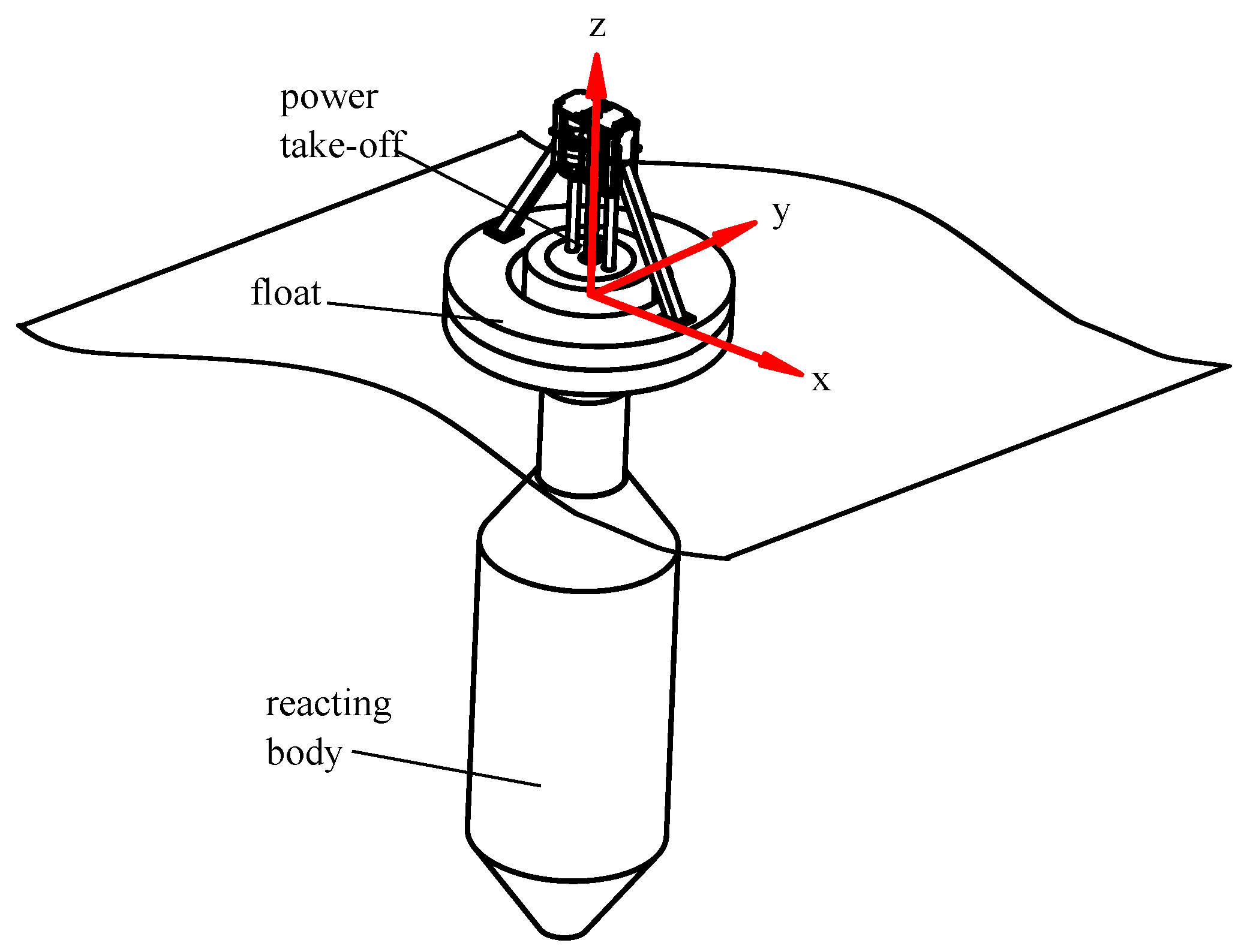
The two-body self-reacting point absorber is modelled on WaveBob™(WaveBob Ltd., Maynooth, Ireland), as shown in Figure 1. This WEC has been benchmarked numerically and experimentally by Beatty [17]. The WEC operates primarily in heave. Forces from incident waves cause the buoyant, toroidal shaped float to react against a second body, referred to as the reacting body. The relative reaction forces do useful work through a power take-off. The power take off force is typically adjusted to optimize the useful work extracted. Summary specifications of the WEC are given in Table 3. Time domain simulations of the point absorber WEC with optimized PTO damping for each sea-state are undertaken to provide the point absorber WEC power time-series. Details on the simulations are given in Appendix A.
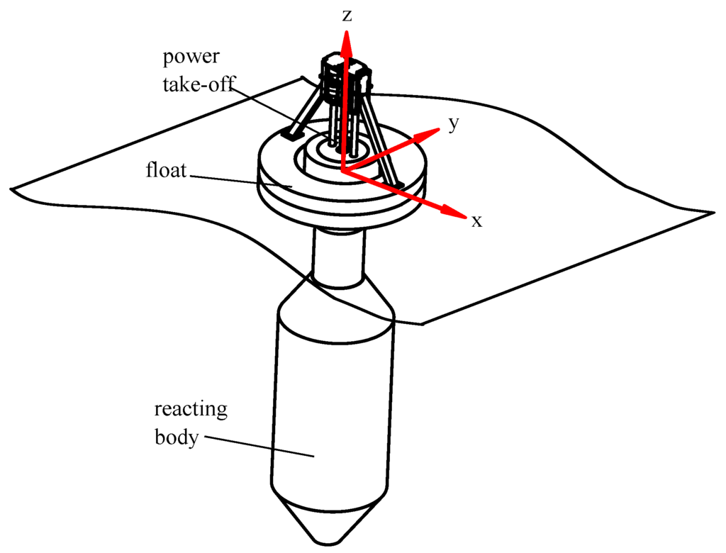
Figure 1.
Schematic of the two-body WEC configuration

Table 3.
Summary specifications of the two-body WEC.
4.4.2. Oscillating Wave Surge Converter
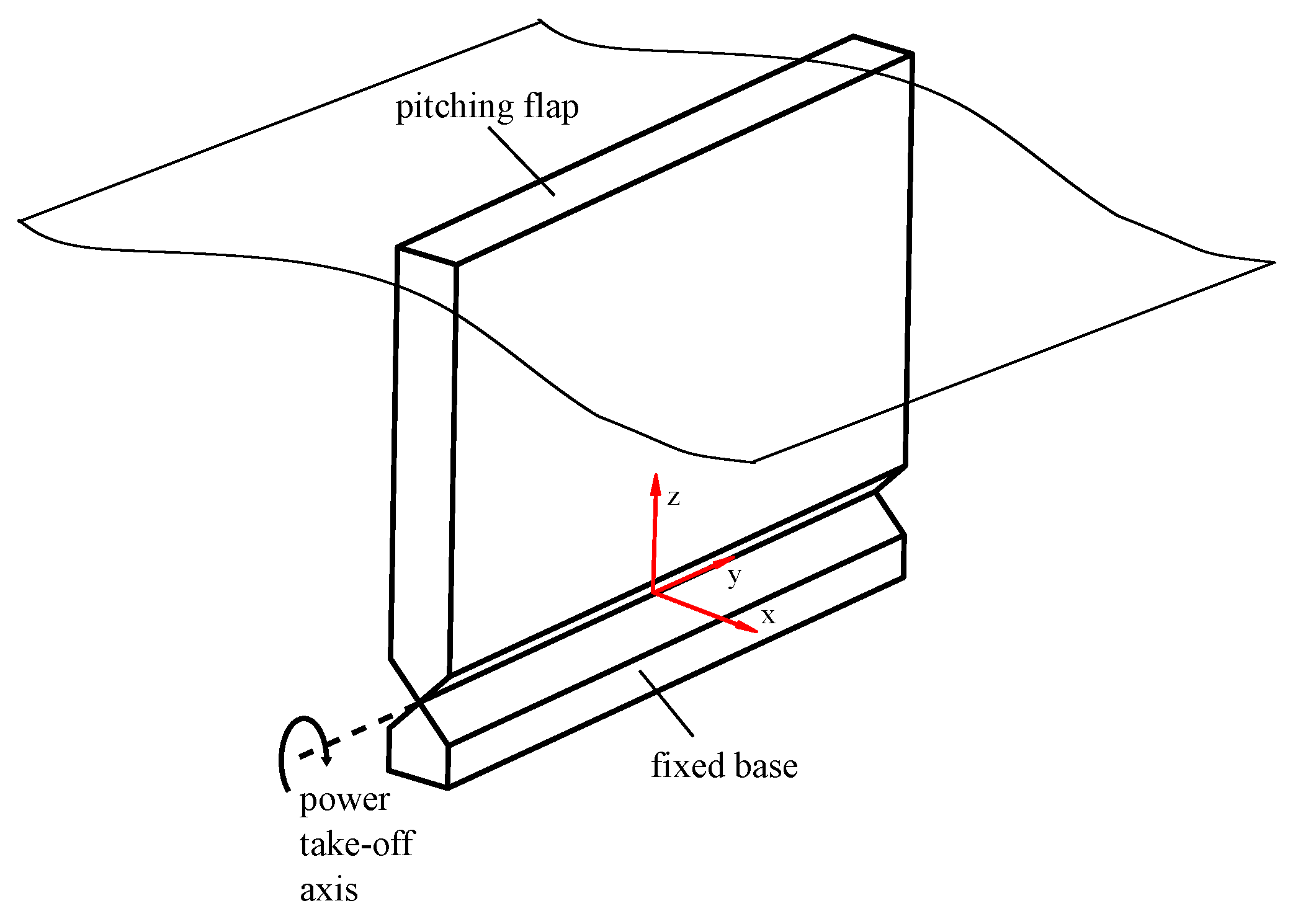
The oscillating wave surge converter is modelled on Oyster™(Aquamarine Power, Edinburgh, Scotland), as shown in Figure 2. The flap, driven by excitation forces from the waves that predominantly travel in the positive x direction, oscillates about a pivot aligned with the y axis as shown in Figure 2. A power take-off in the pivot joint extracts energy from the rotation of the flap relative to the fixed base. The flap’s physical properties are given by Table 4 identical to the OWSC studied by Hoff [18]. In this work, the flap is situated in a water depth of 25 m. The pivot is set to 8.9 m below the still water level and the top of the flap is coincident with the still water level.
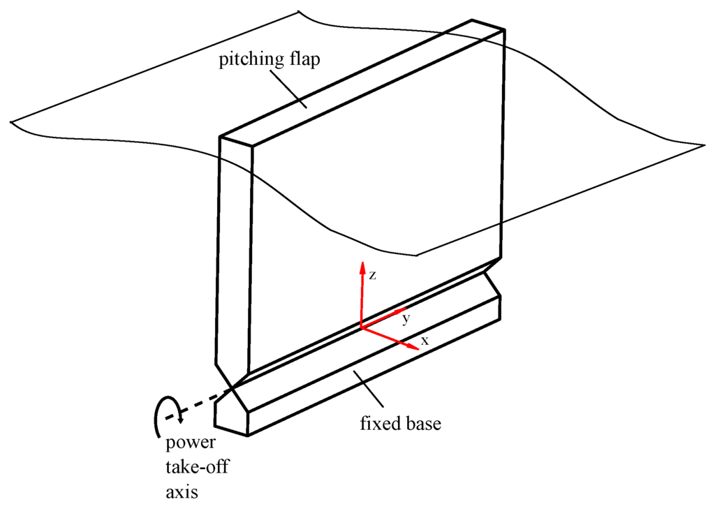
Figure 2.
Schematic of the Flap WEC configuration.

Table 4.
Summary specifications of the pitching flap WEC.
Time domain simulations of the OWSC with optimized PTO damping for each sea-state are undertaken to provide the OWSC power time-series. Details in on the simulations are given in Appendix B.
4.5. Monte Carlo Simulations & Uncertainty Analysis
MAEP is calculated for each WEC and location using Equation (3). To assess variations in MAEP estimates, Monte-Carlo simulation (MCS) is used. The MCS is employed to determine how uncertainty in the WEC deployment and historic met-ocean data time-series affect the uncertainty in the MAEP; in particular, the relative influence of climate, sampling and modelling on uncertainty of MAEP estimates. These categories apply to both the WEC deployment data and the historic met-ocean data and roughly correspond to the categories defined by Livermore [4]: historic resource estimation, future resource variability, model error and performance characterization.
The uncertainty sources which are captured in this analysis are indicated in Table 1. Instrument accuracy is not included directly, but does enter the analysis as part of the modelling error. Measurement interference, short-term data synthesis and data quality are not applicable to the current analysis, so are not included. The state of knowledge of how climate change will impact global and regional wave climates is still developing, so this uncertainty is not included. The uncertainty associated with wave model inputs is manifested in the model error. The uncertainty associated with availability, electrical losses performance degradation (bio-fouling) and curtailment are outside the current scope of study and not included. Only a single WEC is considered so array interactions are not included.
4.5.1. Climate Uncertainty in the Historic Met-Ocean Data
Climate uncertainty in the historic met-ocean time-series arises because a limited duration historical record is being used to estimate the wave climate over the lifetime of the proposed future WEC deployment. In the MCS, this uncertainty is handled by boot-strap re-sampling (with replacement) of the 36 year historic record at one-year lengths. Alternative realizations of the historic record are constructed by randomly assembling the 1 year data windows. This approach captures the dominant seasonal oscillation of the wave climate, but obscures multi-year correlation of wave conditions due to climactic oscillations such as the Pacific Decadal Oscillation and the North Atlantic Oscillation. It also assumes that the wave climate is well represented by the historic record; in this case a 36 year record is used, so this assumption is likely reasonable.
4.5.2. Sampling Uncertainty in the Historic Met-Ocean Data
Sampling uncertainty in the historic met-ocean time-series arises when a limited duration sample is used to estimate the underlying wave spectrum. One approach account for sampling variability is to perturb the variance density estimates in each bin of the spectrum by a random variable with two degrees of freedom, then re-calculate the wave parameters [19]. However, the computational expense of this approach impedes its use within the MCS. Consequently the sampling variance of the and time-series were calculated from the spectral moments (assuming the no correlation between the locations) [7,19]. Forristall [20] notes that for practical purposes the sampling distribution of can be approximated as normal; for the purposes of this work it is assumed that the same applies to the sampling distribution of . In the MCS, each and record in the time-series is perturbed randomly and independently based on the sampling variance. This approach ignores the potential correlation between the perturbations of and , but has been found to be acceptably accurate [6] and computationally efficient. The wave power is calculated from the perturbed parameters as in Equation (2).
4.5.3. Modelling Uncertainty in the Historic Met-Ocean Data
Modelling uncertainty in the historic met-ocean time-series arises because hind-cast model results define the historic met-ocean time series. If measurements were used, then measurement uncertainty, including the effect of missing data, would be applicable. In this application an approximate average scatter index (SI) for (0.20) and (0.12) is obtained from a performance assessment of the European Centre for Medium-Range Weather Forecasts (ECMWF) interim reanalysis (ERA-Interim) model [14]. Based on the authors’ experience with other wave models, a normal distribution provides a reasonable representation of the normalized error in each parameter. In the MCS, each and record in the historic time series is multiplied by the associated SI to get an associated estimate of the standard deviation. Then the standard deviation is used to randomly and independently perturb each and record. Wave power transport is then re-calculated as in Equation (2).
4.5.4. Climate Uncertainty in the WEC Deployment Performance Data
Climate uncertainty in the WEC deployment performance time-series arises because a limited duration deployment is being used to estimate the long-term performance of the WEC. Where the WEC is sensitive to met-ocean parameters not included as dimensions in the performance matrix, it will be necessary to have a population of records in each bin that is representative of the long term average wave climate. In the MCS, this uncertainty is handled by boot-strap re-sampling (with replacement) of the deployment record at one-month lengths (with months sampled in order). This approach ignores correlation of wave conditions at time-scales greater than one month, but is necessary to allow sufficient re-sampling of the 10 year deployment data-sets in the MCS.
4.5.5. Sampling Uncertainty in the WEC Deployment Performance
Sampling uncertainty in the WEC deployment performance time-series arises when the wave measurement instrument (WMI) is not situated at the exact location of the WEC (as is typical in areal WEC deployment). In the MCS, sampling variability of the deployment data is handled in the same way as with the historic met-ocean data-set.
4.5.6. Modelling Uncertainty in the WEC Deployment Performance Data
Modelling uncertainty in the WEC deployment performance time-series arises because a numerical model was used to estimate the production of the WEC. If measurements from a real WEC deployment were used, then measurement uncertainty, including the effect of missing data, would be applicable.
The experimental and validation work of Beatty [17] shows a standard deviation of the SRPA numerical model to measured power to be 25%. Because very few experimental sea-states are presented in Hoff’s work with the OSWC [18], the same uncertainty value for the SRPA was assumed to the OSWC model. In the MCS, each average power record in the deployment time-series is re-selected as a normal random variable with a mean equal to the modelled value and a standard deviation of 25% of the modelled value.
4.5.7. Monte Carlo Simulation Procedure
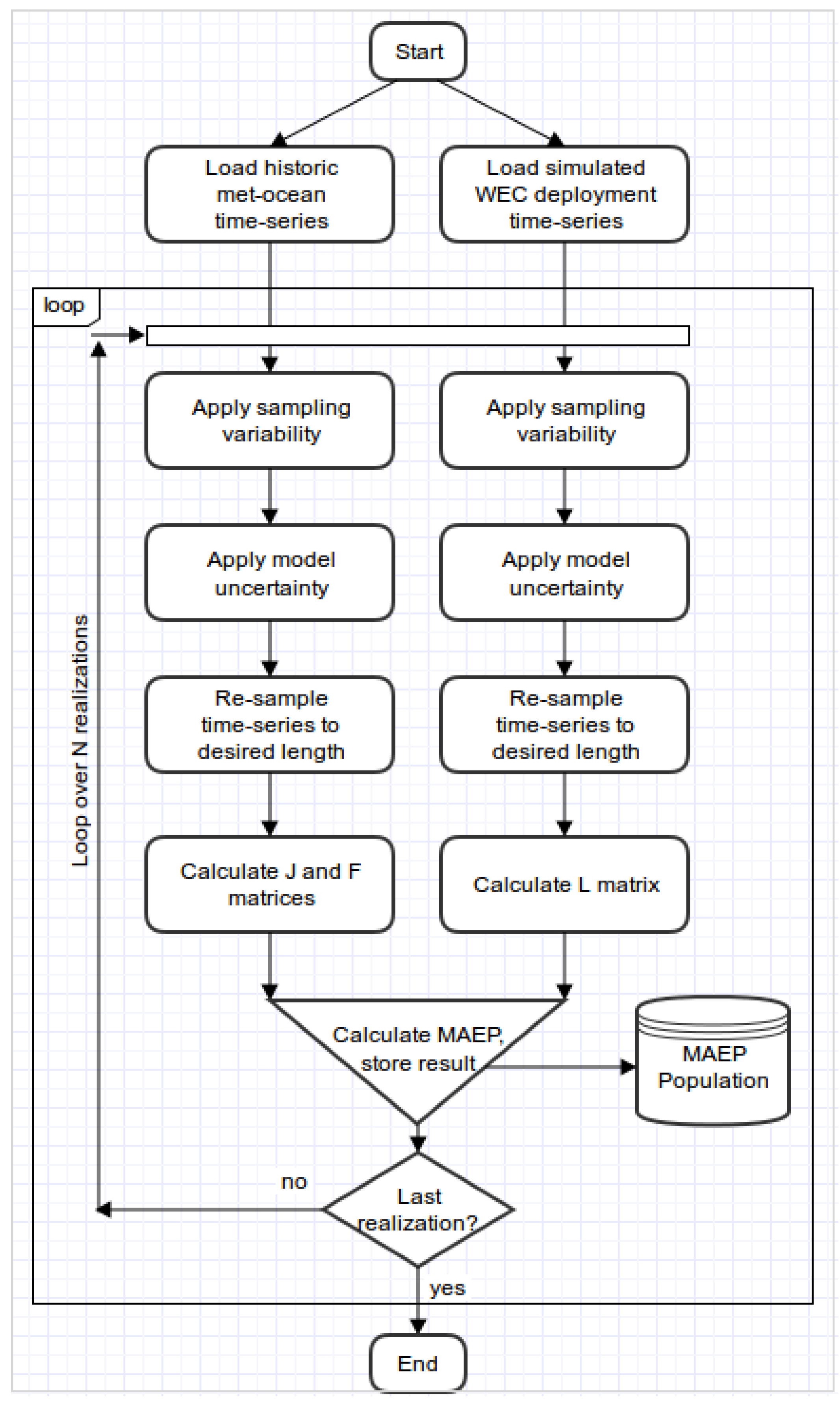
The MCS procedure is illustrated by the flow chart in Figure 3. The process starts by loading the historic met-ocean and WEC deployment data-sets, which are stored and used as inputs to the simulation loop. First each data-set is perturbed by the associated sampling variability. Following that each data-set is perturbed by the associated modelling uncertainty. Finally each data-set is boot-strap re-sampled to account for climate variability. From the perturbed/re-sampled historic met-ocean data set the mean wave power and frequency of occurrence matrices are calculated. From the perturbed/re-sample WEC deployment data-set the mean capture length matrix is calculated. The MAEP is then calculated as per Equation (3) and stored in a data-base. This procedure is then repeated N = 10,000 times to create a statistically robust population of MAEP realizations. Statistical methods can then be applied to the MAEP population to estimate confidence intervals, assess distribution shape and examine sensitivities. These statistical parameters are compared to the ‘true’ MAEP, calculated using Equation (3), where and is calculated from the complete, un-altered historic met-ocean data-set and calculated from the complete and un-altered WEC deployment data-set.
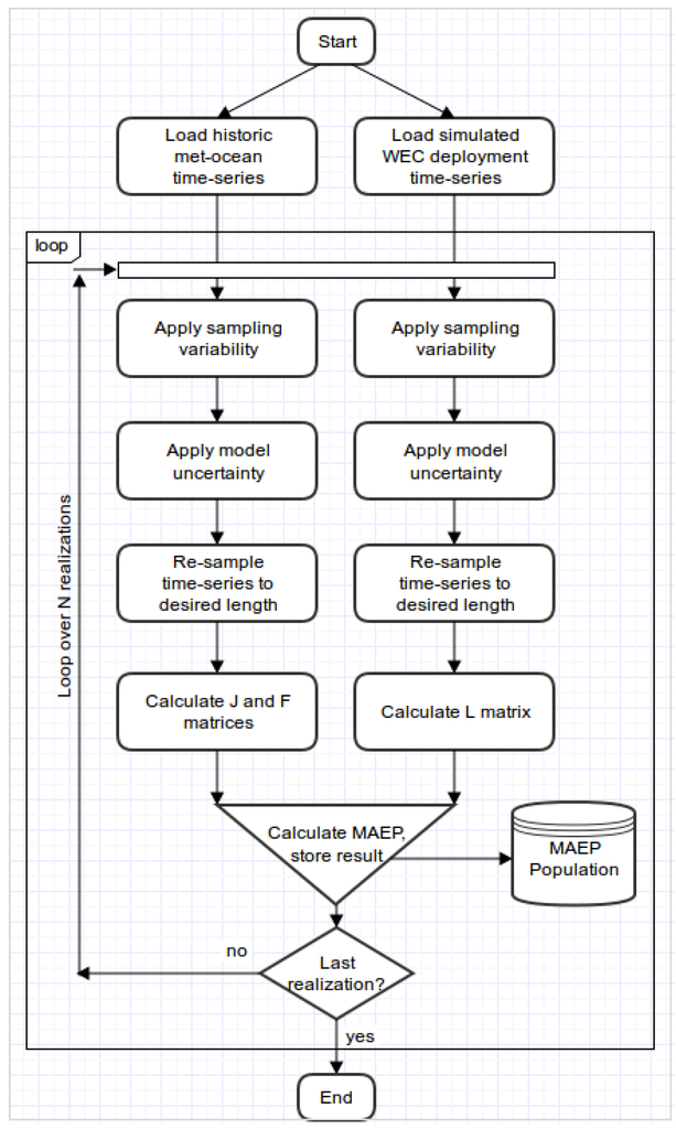
Figure 3.
Flow chart of Monte Carlo simulation execution.
The Canadian historic met-ocean data-sets lack sufficient length to enable the MCS, therefore the they are not included in the MAEP uncertainty analysis. They are, however, retained and published for future analysis.
5. Wave Data Analysis Results
5.1. Wave Matrices
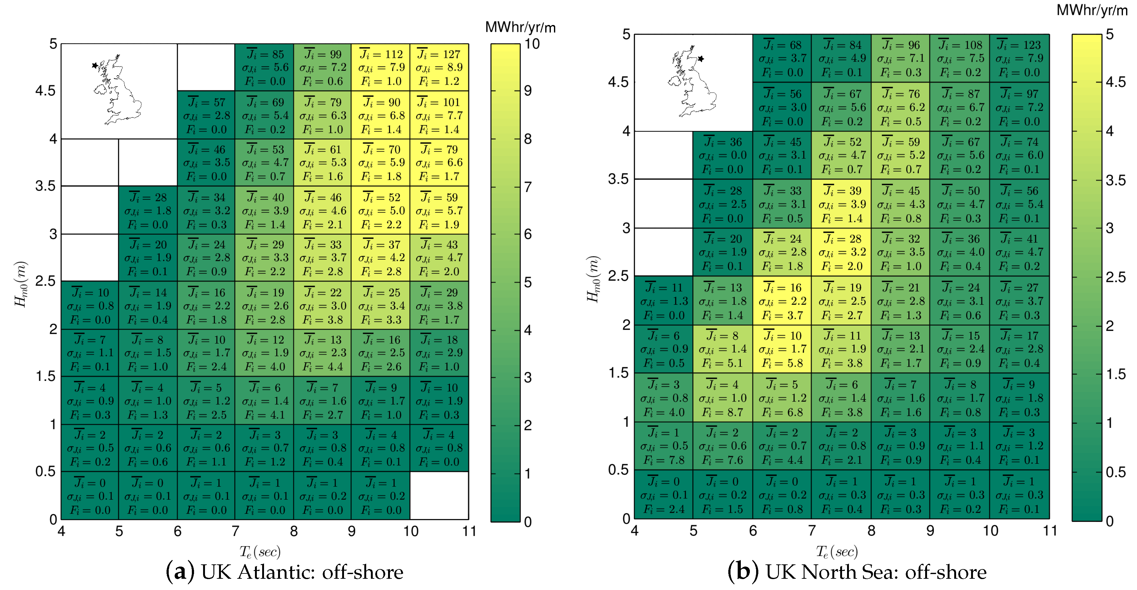
The method of bins was used to calculate the wave power transport and frequency of occurrence matrix for all four UK sites. In each bin the mean, minimum, maximum and standard deviation of wave power is calculated. Additionally, the average annual energy flux is calculated to indicate the relative importance of each bin. The results are presented in Figure 4 for the UK Atlantic and North Sea off-shore site.
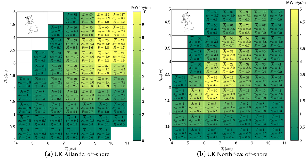
Figure 4.
Wave matrices for UK offshore sites. Text indicates mean and standard deviation of wave power (, , in kW/m) and frequency of occurrence ( as a percentage). Color indicates average wave energy in MWhr/yr/m.
Comparing Figure 4a,b we can see that bin-to-bin, the mean and standard deviation of J is similar, but not exactly the same between the figures, even in bins with a high frequency of occurrence. These small differences result from the distribution of records within the bin, which if not uniform over the bin, can skew the mean and standard deviation.
Bin-to-bin, the frequency of occurrence differs significantly between Figure 4a,b. At the Atlantic location (Figure 4a) is evenly distributed at about the 2%–4% level over a large range of bins. This range occurs because of the large expanse (fetch) of the Atlantic Ocean and its capacity to generate a large range of wave conditions (). In the North Sea location (Figure 4b) is more concentrated, in the low and region of the matrix (). This limited range occurs because of the limited expanse of the North Sea and its limited capacity to generate waves with large height and period.
At the Atlantic site (Figure 4a) the bins with largest annual energy flux occur at large wave heights and long periods (). By contrast, at the North Sea site (Figure 4b) the bins with the largest energy flux occur at moderate wave heights and long periods (). The difference in annual energy occurs due to the differing distribution frequency of occurrence distribution between the two sites.
The results for the near-shore sites are similar, with frequency of occurrence and annual energy flux shifted toward lower wave height values.
5.2. Average Wave Spectrum
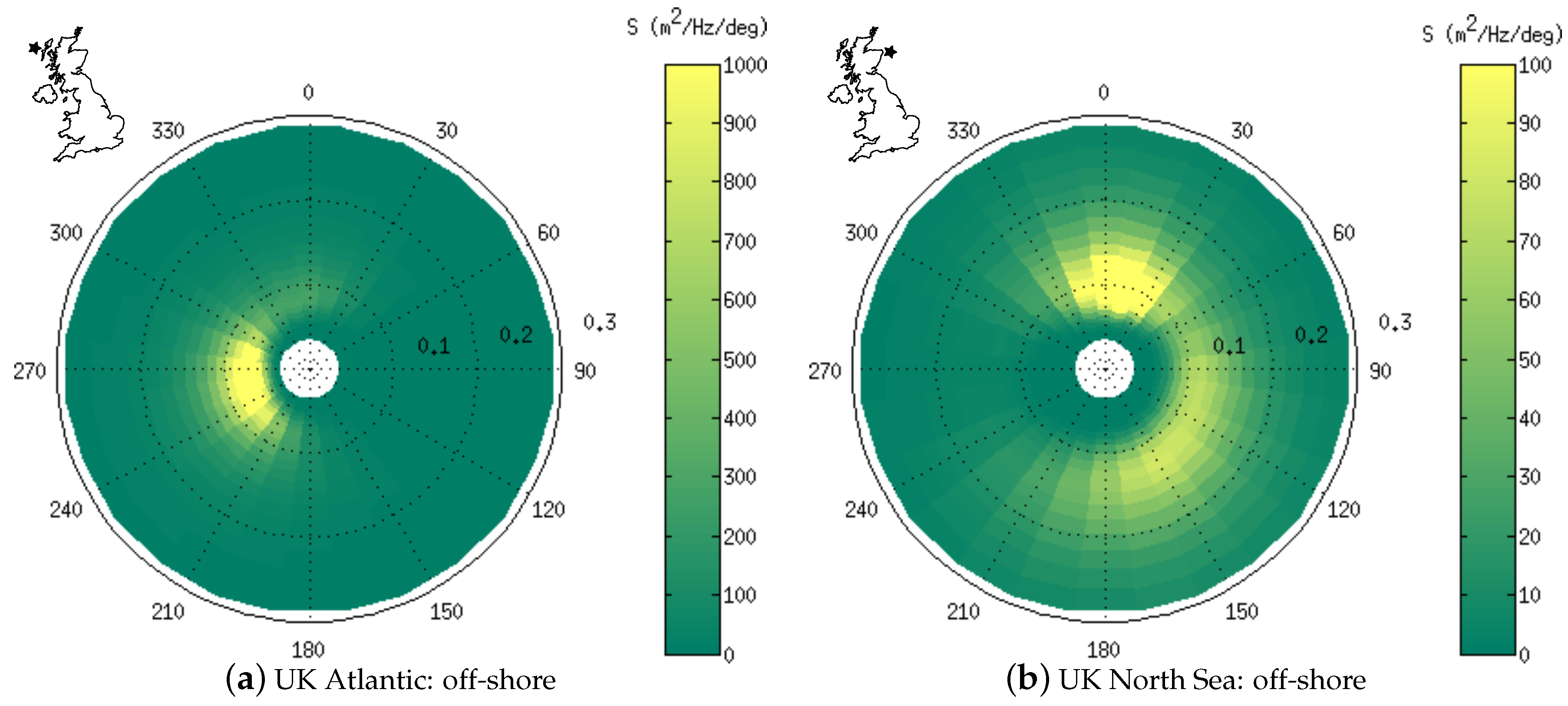
To illustrate the typical direction-frequency distribution of wave energy, the average wave spectrum was calculated for all four UK sites. Figure 5 shows the average spectra at the UK Atlantic and North Sea off-shore sites.
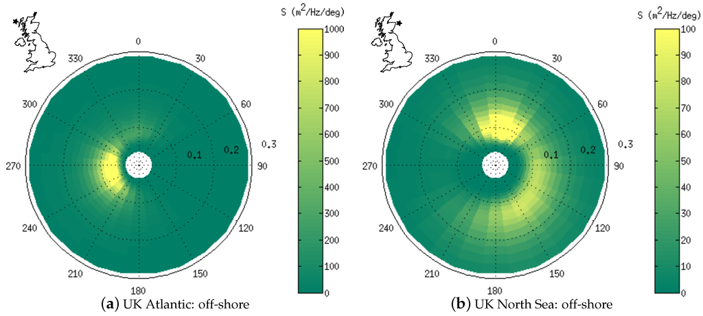
Figure 5.
Average wave spectra at the UK off-shore sites. The polar angle axis indicates the direction of the spectral bin in nautical convention; the radial axis indicates the frequency of the spectral bin in Hz.
At the Atlantic location (Figure 5a), the average wave energy is concentrated in directions ranging from about 210° to 300° and frequencies less than 0.1 Hz. This is because most of the wave energy arriving at the Atlantic location is not generated locally, so that sheltering and refraction filter the directional range and wave dispersion filters the frequency range.
At the North Sea location (Figure 5b), the variance is spread through directions ranging from 300° to 180° (CW) and frequencies from about 0.05 to 0.2 Hz. This is because most of the wave energy arriving at the North Sea site is generated locally (within the North Sea), so that the direction and frequency of any wave system is highly linked to the characteristics of the weather system which generated those waves.
The variance density at the North Sea site is about an order of magnitude less concentrated than at the Atlantic site.
6. WEC Simulation Results
Simulated WEC deployments were executed at each of the sites over the years 2004 to 2013. The SRPA model was simulated at hourly intervals, the OWSC was simulated at 3 h intervals. The WEC power time-series from each simulation was averaged to give an average absorbed power value () for each interval. These average power values are collected over the 10 year deployment to give a time-series of average power. The wave and power parameters associated with each simulated deployment collected together into a single data-base2.
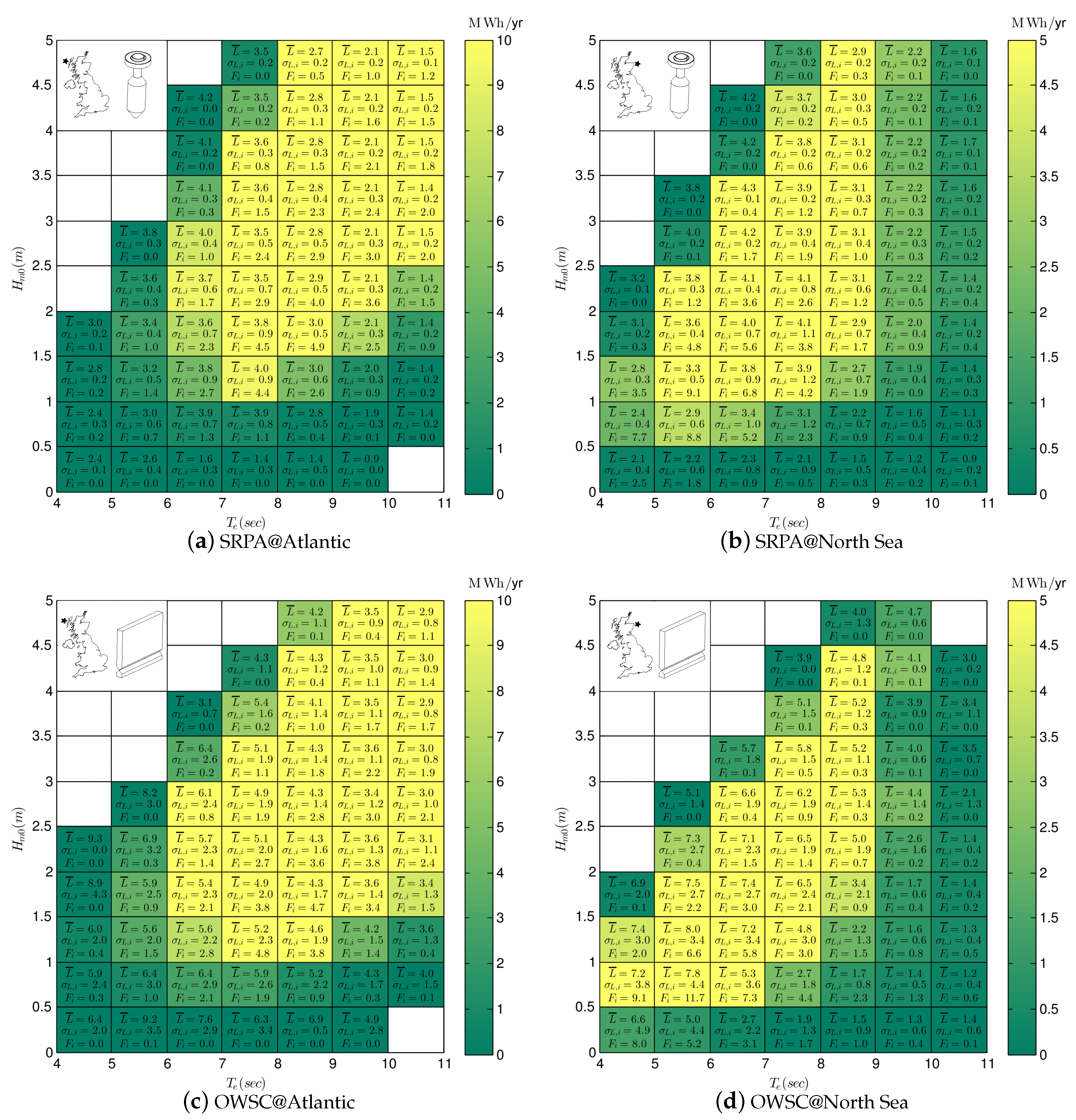
The method of bins was used to calculate the capture length and frequency of occurrence matrix for all four UK sites. In each bin the mean, minimum, maximum and standard deviation of capture length is calculated. Additionally, the average annual energy absorption is calculated to indicate the relative importance of each bin. The results are presented in Figure 6 for the SRPA and OWSC the UK Atlantic and North Sea sites.
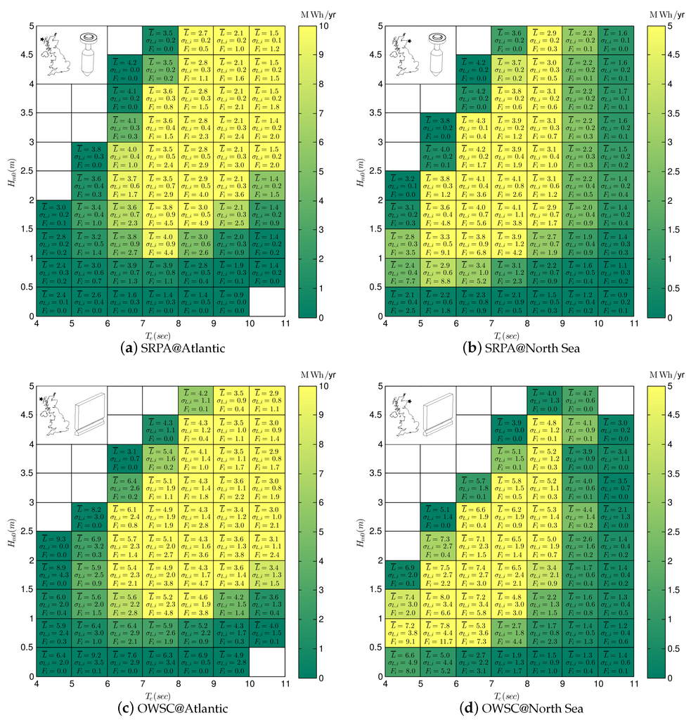
Figure 6.
WEC performance matrices. Text indicates mean and standard deviation of capture length (, , in m) and frequency of occurrence ( as a percentage). Colour indicates average annual energy absorption in MWhr/yr.
6.1. SRPA Performance Matrix
Comparing the SRPA results in Figure 6a,b, we can see that bin-to-bin, the mean and standard deviation of L is significantly different between the sites. It appears that this difference results from the typical distribution of wave energy within the spectrum at the two sites: in the Atlantic the wave energy is concentrated in low frequency portions of the spectrum, in the North Sea the variance is much more distributed in frequency (see Figure 5). The SRPA operates most efficiently when variance is concentrated near its optimal operating frequency, about 0.12 Hz [17]. Though the wave energy at the Atlantic is concentrated, it is in a part of the spectrum below the optimal operating frequency of the SRPA. At the North Sea site, the wave energy is much more distributed, but more of that variance is around the optimal operating frequency of the WEC. Consequently, the SRPA has a lower mean and variance of L at the Atlantic site compared to the North Sea site.
The large range of at the Atlantic site (Figure 6a) combined with the low gradient in L means that the bins with the largest energy absorption occur at relatively large wave heights and long periods (). By contrast, the limited range of at the North Sea site (Figure 6b) means that the bins with the largest energy absorption occur at moderate wave heights and periods ().
6.2. OWSC Performance Matrix
Comparing the OWSC results in Figure 6c,d, we can again see that bin-to-bin, the mean and standard deviation of L is significantly different between the sites. The OWSC has an optimal operating frequency around 0.10 Hz [18]. At the North Sea site more of the wave energy is concentrated around this optimal operating frequency, so on average the OSWC performs better than at the Atlantic site. However, there is much more variance in direction at the North Sea site, so is larger compared to the Atlantic site.
The large range of at the Atlantic site (Figure 6c) combined with the low gradient in L means that the bins with the largest energy absorption occur at relatively large wave heights and long periods (). By contrast, the limited range of at the North Sea site (Figure 6d) means that the bins with the largest energy absorption occur at moderate wave heights and periods ().
6.3. Comparison of Performance Between WECs
Comparing the capture length matrices of the SRPA (Figure 6a,b) and the OWSC (Figure 6c,d), the L of the OWSC is, as expected, larger owing to its’ larger horizontal dimension. The of the OWSC is also significantly larger. This appears due to the sensitivity of the OWSC to directionality. In these simulations the OWSC was located about 25 m of water depth. At this depth refraction has not completely dominated wave direction and multi-directional seas are still possible. If the OWSC had been located at the shoreline, where refraction is dominant, then variance in wave direction would be reduced and likely with it .
6.4. Comparison of Performance Locations
The differences in the L matrices for the same WEC between Atlantic and North Sea sites illustrates the difficulty in estimating MAEP at a second prospective location: the prevailing sea conditions affect the performance of the device, resulting in a distinctly different L matrix for each location. If the L matrix from location 1 is used to estimate performance at location 2, a biased estimate of MAEP is expected. To estimate MAEP at a second location requires a more detailed procedure for performance characterization [21].
7. MAEP Uncertainty Assessment Results
Using Monte Carlo simulation as described in Section 4.5, populations of MAEP estimates were generated for each WEC deployment. Each MAEP population was then used to perform a number of statistical calculations.
7.1. Distribution of MAEP
It was hypothesized that the MAEP population may follow a normal distribution. For each deployment, this hypothesis was testing using the Kolmogorov-Smirnov test. Where a sufficiently long met-ocean and WEC deployment data-set have been used, the null hypothesis of the normal distribution is generally not rejected at the 5% significance level; for the SRPA, this requires a minimum of about 2 years of met-ocean and 6 months of deployment data, for the OWSC, requires about 4 years of met-ocean and 12 months of deployment data. The difference appears to be due to the difference in between the devices.
Having established that the population of MAEP generally follows a normal distribution, in the following analysis we will use the standard deviation of MAEP () to describe the population variance.
7.2. Statistics of MAEP
Table 5 provides ‘true’ MAEP along with the mean (μ), standard deviation (σ) and the 5, 50 and 95 percentiles () of MAEP for WEC deployment. These results are for a historic met-ocean data length of 10 years and WEC deployment length of 12 months.

Table 5.
Results from the MCS for historic met-ocean data length of 10 years and WEC deployment length of 12 months. MAEP results in units of MW-hr.
For both WECs, the mean estimate of the MAEP tends to under-estimate the ‘true’ MAEP. This bias reduces as the length of met-ocean and deployment data-sets are increased. The bias appears to have two sources: (1) where an insufficiently long data-set is used, some of the bins in the matrix will remain empty and not contribute to the total MAEP; (2) when the wave parameters in the met-ocean data-set are perturbed by the modelling uncertainty, sometimes the perturbed value will land in a bin outside the defined range of the L matrix and consequently not contribute to the total MAEP.
For both WECs, the standard deviation of the MAEP estimates are considerably higher at the North Sea sites (relative to the mean estimate). The factors contributing to this result are investigated in the next section.
7.3. Assessment of Relative Contributions to MAEP Uncertainty
The relative contributions of the uncertainty sources to the MAEP uncertainties were assessed with MCS using 10 years of met-ocean data and 12 months of WEC deployment data. In this assessment, 7 different MCS were performed for each WEC deployment. In the first 6 MCS, only a single source of uncertainty was activated in the MCS. In the final MCS, all sources of uncertainty were activated. Table 6 shows the standard deviation of MAEP () for each test presented as a percentage of the ‘true’ MAEP.

Table 6.
Standard deviation of MAEP () as a percentage of ‘true’ MAEP for a deployment length of 12 months and a met-ocean data length of 10 years. First 6 rows are evaluated based on a MCS with only a single uncertainty source enabled. The seventh row is evaluated based on a MCS with all six sources of uncertainty enabled simultaneously.
Observing Table 6, the influence of climate variability on is large compared to the influences of sampling variability and modelling uncertainty. For the SRPA, the variability of the climate in the historic met-ocean data-set is the largest single uncertainty, for the OWSC it is the variability of the climate in the WEC deployment data-set. The dominance of climate variability implies that, using the performance matrix approach, there is minimum level of uncertainty in MAEP estimates which is unavoidable due to limited data availability.
7.4. Sensitivity to Data Length
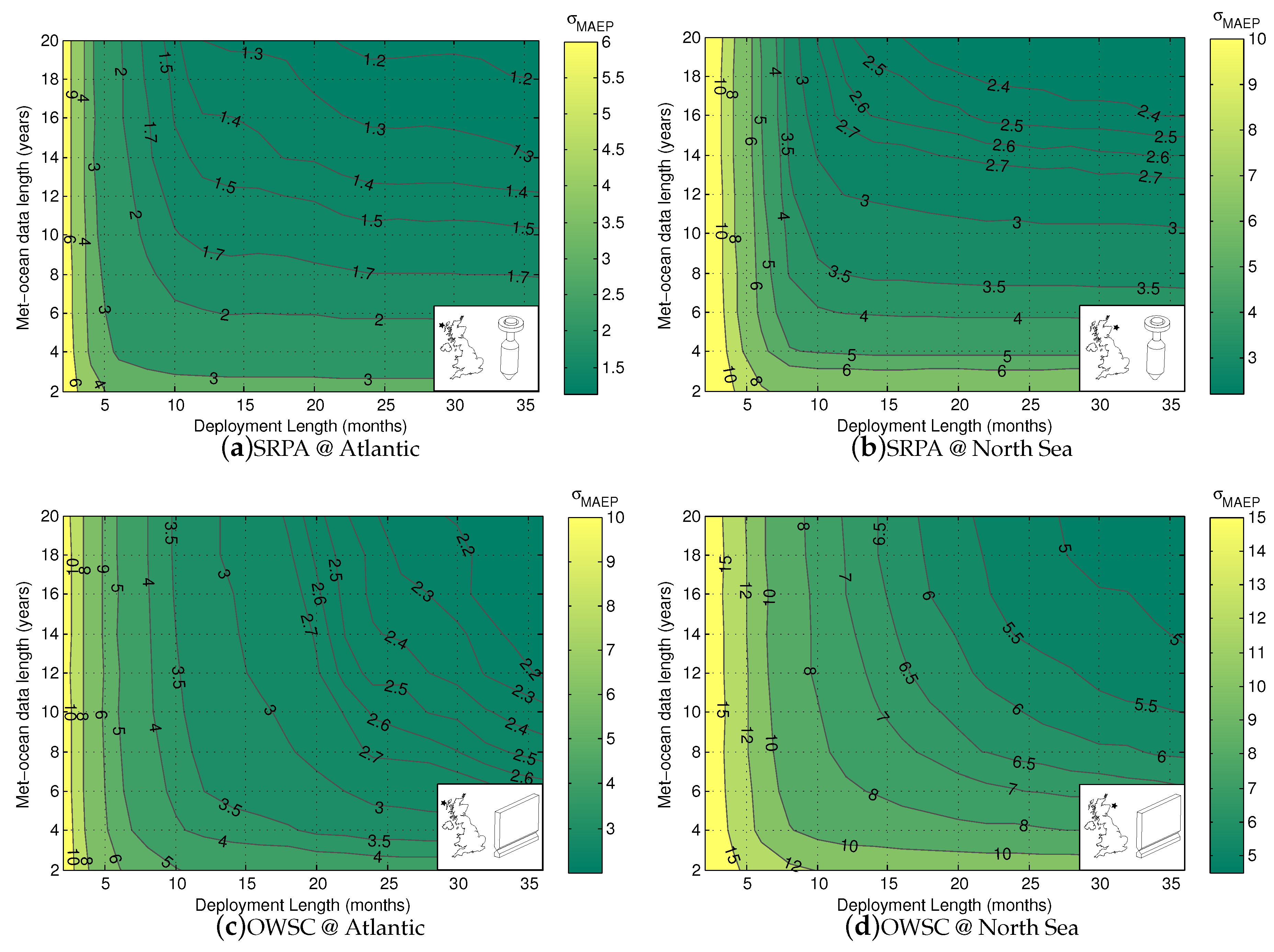
One of the outstanding questions in WEC performance assessment is: what lengths of the historic met-ocean and WEC deployment data-sets are required to yield robust estimates of MAEP? Insight on this issue may arise from checking the sensitivity of to data length. The was calculated for a large range of WEC deployment and historic met-ocean data-set lengths. For each deployment, 180 MCS were executed. The length of the WEC deployment was varied from 2 to 36 month at 2 month intervals. The length of the historic met-ocean data-set was varied from 2 to 20 years at 2 year intervals. The collated results for each deployment are presented as contour plots of in Figure 7, one for each WEC/location combination.
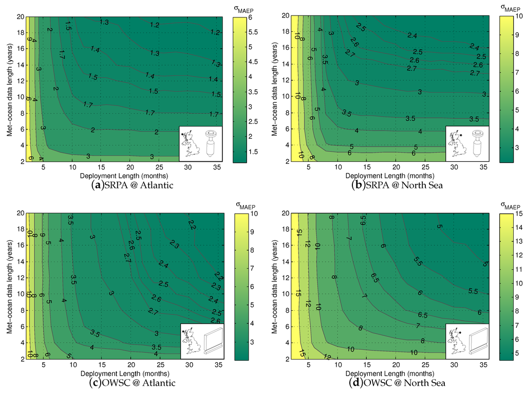
Figure 7.
Contours of as a percentage of the ‘true’ MAEP as a function of historic met-ocean and WEC deployment data length.
7.4.1. The SRPA
Figure 7a, for the SRPA at the Atlantic site, shows that decreases steeply in the deployment length direction between 2 and 12 months, after which the gradient is much milder. This result provides evidence to support the intuition that accurate characterization of WEC performance requires operating through the seasonally varied conditions of a complete year.
In the met-ocean length direction of Figure 7a, a mild gradient in is present for the full 2 to 20 years. This implies small but significant year to year changes in the J and F matrices, such that even with 20 years of data, they are not fully characterized.
Where the WEC deployment length is 12 months or longer, of the SRPA is more sensitive to met-ocean data length than WEC deployment data length. This agrees with the results presented in Table 6, where it was found that the climate variability of the met-ocean data set was the largest contributor to .
Comparing Figure 7a,b, for the SRPA at the Atlantic and North Sea sites, we see a significant difference in the contours. While the same general shape exists, is significantly larger for the North Sea site. This is likely due to the more distributed nature of wave energy at the North Sea site. Sea conditions are much less consistent at this site compared to the Atlantic, so there will be more variance in energy production over any given time-scale.
7.4.2. The OWSC
Figure 7c, for the OWSC at the Atlantic site, shows that decreases steeply in the WEC deployment length direction between 2 and 12 months, after which the gradient is more moderate, but still significant. This again suggests the necessity of a full year deployment for WEC performance characterization, but also indicates that the OWSC performance is sensitive to parameters which vary on time-scales longer than the seasons—potentially prevailing wave direction.
In the met-ocean length direction Figure 7c, a mild gradient in is present for the full 2 to 20 years. This result is similar to that found for the SRPA and implies small but significant year to year changes in the J and F matrices, such that even with 20 years of data, they are not fully characterized.
Where the WEC deployment length is longer than 20 months, is about equally sensitive to met-ocean data length (in years) and WEC deployment data length (in months). This agrees with the results presented in Table 6, where it was found that the climate variability of the met-ocean data-set and the WEC deployment data-set contributed similarly to .
Comparing Figure 7c,d, for the OWSC at the Atlantic and North Sea sites, we see a significant difference in the contours. While the same general shape exists, is larger for the North Sea site. This is likely due to the more distributed nature of wave energy at the North Sea site. Sea conditions are much less consistent at this site compared to the Atlantic, so there will be more variance in energy production over any given time-scale.
7.4.3. Discussion
The contours of vary significantly from location to location and device to device. For this reason, it seems inappropriate to set specific data-length requirements for either the historic met-ocean data-set or the WEC deployment data set within standards or best practice documents. Instead it seems reasonable to set a target level of . With this approach, the required lengths of the met-ocean and deployment data-sets would be different for each WEC-location combination. This recommendation goes against current standard practice which specifies a set minimum length for each data-set. The drawback of this approach is that it requires a detailed and computationally expensive modelling study as conducted in this work.
This study has assessed the variability of MAEP estimates, not the uncertainty in energy production associated with a prospective project. For the latter case one would need to combine two uncertainties (1) the uncertainty in the estimate of the MAEP based on the lengths of the available met-ocean and deployment data-sets and (2) the uncertainty that the average energy production during the project lifetime is equal to the MAEP, based on the life-time of the project.
8. Conclusions
Several WEC deployments were simulated using time-domain numerical models. Two WECs with fundamentally different operating principles were simulated: a self-reacting point absorber (SRPA) inspired by WaveBob™, and an oscillating wave surge converter (OWSC) inspired by the Oyster™. Each simulated deployment is ten years in length. Each WEC was simulated in four different deployment locations: the Canadian Pacific, the Canadian Atlantic, the UK Atlantic and the UK North Sea. Parametric wave data and WEC power data from all of the simulations has been made freely available.
The wave climate and the WEC performance were characterized by matrices as a function of wave parameters -. The wave climate was quantified in terms of wave power transport and frequency of occurrence; WEC performance was quantified in terms of capture length. Monte Carlo simulation methods were used to assess the relative contributions of climate variability, wave and WEC modelling uncertainty and wave and WEC sampling variability on the variability of MAEP estimates.
From the simulation study and subsequent data analysis the following conclusions are drawn:
- Wave occurrences at the UK Atlantic site are spread over a wide range of and and the energy in the average wave spectrum is concentrated in swell frequencies with a narrow directional window.
- Wave occurrences at the North Sea site are concentrated at the lower ranges of and and the energy in the average wave spectrum is spread through a wide swath of frequencies and directions.
- For the same sea-state, both WECs tends to operate with a higher capture length at the North Sea site compared to the Atlantic site.
- For the same sea-state, the OWSC tends to have a larger variability of capture length compared to the SRPA.
- For the same WEC, the capture length matrix for the simulated deployments is substantially different between the Atlantic and North Sea sites.
Monte Carlo Simulation techniques were used to study the uncertainty of mean annual energy production estimates, specifically the uncertainty associated with sampling, modelling and climate variability . From this investigation the following is concluded:
- Under most conditions, the MAEP populations are reasonably approximated by a normal distribution.
- MAEP estimates tend to under-predict MAEP due to missing data.
- Climate variability contributes most of the uncertainty to MAEP estimates.
- The MAEP of the SPRA is most sensitive to climate variability in the historic met-ocean data-set.
- The MAEP of the OWSC is most sensitive to climate variability in the WEC deployment data-set.
- The uncertainty in MAEP estimates vary significantly with the length of the historic met-ocean and WEC deployment data-sets used in the calculation.
- The uncertainty in MAEP estimates vary considerably between WECs and locations: variance in MAEP is higher for the OSWC and for the North Sea location.
- If a certain maximum level of uncertainty in MAEP is targeted, the minimum required lengths of the historic met-ocean and WEC deployment data-sets will be different for every WEC-location combination.
While this work provides new insight into the key factors contributing to the uncertainty in MAEP estimates, the work is limited by: (1) the sources of uncertainty considered; (2) the assumptions made in the Monte Carlo simulations and (3) the simplifications made in the WEC numerical models. Given the apparent sensitivity of MAEP uncertainty to climate variability, future work should critically assess of the implications of the temporal window size used in the boot-strap re-sampling of the WEC deployment and historic met-ocean data.
Acknowledgments
The authors gratefully acknowledge funding support from Marine Renewables Canada; in-kind contributions from Cascadia Coast Research Ltd., The University of Edinburgh and the University of Victoria West Coast Wave Initiative; and support for open access publishing from the Engineering and Physical Sciences Research Council (Edinburgh).
Author Contributions
C.E.H., S.J.B. and A.d.A. together identified the need for this work; S.J.B. developed and validated the SRPA model; A.d.A. and S.J.B. developed and validated the OWSC model (based on [18,22]); S.J.B. and C.E.H. executed the models using University of Victoria computational resources; C.E.H. conceived and designed and executed the statistical analysis with input from A.d.A. and S.J.B.; S.J.B. contributed Appendix A and Appendix B; C.E.H. wrote the paper; S.J.B. and A.d.A. performed critical editing.
Conflicts of Interest
The authors declare no conflict of interest.
Nomenclature
| Significant wave height (m) | |
| Wave energy period (sec) | |
| P | Average WEC power output (kW) |
| J | Wave power transport (kW/m) |
| L | Capture length (m) |
| g | Acceleration due to gravity (m/s2) |
| Wave group velocity (m/s) | |
| i | Linear index of a matrix bin |
| Overbar indicates that the enclosed parameters is a matrix of bin-averaged values | |
| S | The variance density (wave Spectrum) (m2/Hz/rad) |
| ω | Circular wave frequency (rad/s) |
| θ | Wave direction (°) |
| MAEP | Estimate of WEC mean annual energy production (MWh) |
| u, v, w | Water particle velocity in the x, y and z directions (m/sec) |
| Sinusoidal component amplitude (m) | |
| j | Index to bin location on the frequency axis of the wave spectrum |
| k | Index to bin location on the direction axis of the wave spectrum |
| Standard deviation of mean annual energy production (MWhr or %) | |
| μ | Mean estimate of mean annual energy production (MWhr) |
| The x percentile of MEAP (MWhr) |
Appendix A. SRPA Simulations
The equations governing the heave dynamics of the SRPA are given by:
where heave displacement, velocity, and acceleration of the float and reacting body are represented respectively by 2 × 1 vectors: , , and . is a 2 × 2 mass matrix combined with the infinite frequency added mass. The remaining terms are 2 × 1 vectors, where are excitation forces, are radiation forces, are Coulomb friction forces, are viscous drag forces, are hydrostatic forces, and finally are PTO forces. As per the Cummins approach [23], radiation and excitation forces are respectively modelled for each body j by the following convolution integrals:
where the radiation and excitation kernel functions are given by:
The convolution integral bounds are chosen to be wide enough so that kernel functions have approached zero in the time ranges (0 to 10 s for radiation, −10 to 10 s for excitation). A sliding friction force is included to account for the friction in the linear guide bearings on which the float and reacting bodies translate. The sliding friction force on body is modelled using the Coulombic model with constant force. The viscous drag force on body j is modelled using the the relative velocity formulation of the Morison drag force [24]:
where is the characteristic diameter, is the drag coefficient, and is taken as the fluid velocity at the depth location of the characteristic diameter. is taken as the float outer diameter and is taken as the largest diameter of the reacting body.
The mean power capture for each SRPA simulation is calculated by Equation (A7), where is instantaneous PTO force and is the instantaneous relative velocity.
A 4th order Runge-Kutta, fixed time-step, integrator with a time step of 0.065 s is used for the time simulations. The time domain model runs at approximately 10:1 real-time.
The power take-off is modelled as a passive damping term that couples the float to the reacting body. The choice of the PTO damping value was made by numerical optimization for each wave spectrum. The optimization problem maximizes power converted, taking the spectrum shape into account. The WEC dynamics in the objective function are calculated using a frequency domain model with experimentally determined, linearized, viscous drag terms, validated in Beatty et al. [17,25].
Appendix B. OWSC Simulations
The OWSC WEC time domain model, is given by Equation (B1).
where pitch rotational displacement, velocity, and acceleration of the OWSC are respectively: Θ, , and . is the pitch mass moment of inertia combined with the pitch added mass at infinite frequency. The remaining terms are external torques about the y axis: where is wave excitation torque, is the radiation torque, is viscous drag torque, is the hydrostatic stiffness torque, and finally is the PTO torque.
The excitation torque is calculated by superposition of the pitch excitation torques from each individual wave component:
where is the frequency and direction dependent excitation torque complex amplitude obtained from WAMIT for the flap geometry. The radiation torque is calculated using a state space model, with rational approximation to the radiation convolution, implemented in Simulink by Forehand [22].
The viscous drag torque is calculated using the method implemented by Babarit et al. [26]. This is done by splitting the face of the OWSC into panels, then the relative velocity form of Morison drag is calculated for each of the panels, yielding the equation:
with the position vector to the centre of panel l as,
and the drag force normal to the panel l,
where are the coordinates of the centroid of panel l, is drag coefficient, is the cross-sectional area of panel l, is the instantaneous velocity of panel l, and is the instantaneous fluid velocity due to the undisturbed wave field at panel l. The hydrostatic restoring torque is calculated using where C is the hydrostatic restoring coefficient taken from Hoff [18].
The power take-off is modelled as a passive damping term on the rotation of the flap relative to the fixed base. The PTO torque is calculated by , where the PTO damping coefficient is chosen for each sea-state by numerical optimization. The choice of the PTO damping value was made by numerical optimization for each wave spectrum. The optimization problem maximizes power converted, taking the spectrum shape into account. The OWSC dynamics in the objective function are calculated using a frequency domain model with linear hydrodynamic coefficients. Viscous drag was neglected in the dynamics model used for the PTO optimization.
The mean power capture for each simulation is calculated by Equation (B6), where is instantaneous PTO torque and is the instantaneous flap angular velocity.
The capture length for each OWSC simulation is again calculated by Equation (1). Non-linear end-stops were implemented at angles of ±90 degrees from equilibrium. A 3rd order Runge-Kutta, fixed time-step, integrator with a time step of 0.1 s was used for the time simulations.
At each location the OWSC was oriented to maximize wave energy exposure. The angle of the outward normal was calculated as the wave energy weighted average of the direction of maximum directionally resolved waved power (, see [13])
where i indicates each time-step in the data set.
References
- IEC/TS 62600-100 ed1.0. Power Performance Assessment of Electricity Producing Wave Energy Converters; International Electrotechnical Commission: Geneva, Switzerland, 2012. [Google Scholar]
- Wavestar A/S. Wavestar Prototype at Roshage—Performance Data for ForskVE Project No 2009-1-10305 Phase 1 & 2; Technical Report; Wavestar A/S: Brøndby, Denmark, 2013. [Google Scholar]
- Babarit, A. A database of capture width ratio of wave energy converters. Renew. Energy 2015, 80, 610–628. [Google Scholar] [CrossRef]
- Livermore, S. Wave and Tidal Energy Yield Uncertainty; Technical Report; Offshore Renewable Energy Catapult: Blyth, UK, 2015. [Google Scholar]
- Guanche, R.; de Andrés, A.; Simal, P.; Vidal, C.; Losada, I. Uncertainty analysis of wave energy farms financial indicators. Renew. Energy 2014, 68, 570–580. [Google Scholar] [CrossRef]
- Mackay, E.B.L. Wave Energy Resource Assessment. Ph.D. Thesis, University of Southampton, Southampton, UK, 2009. [Google Scholar]
- Mackay, E.; Ashton, I. Sampling Variability and Performance Assessment of WECs. In Proceedings of the European Wave and Tidal Energy Conference, Aalborg, Denmark, 2–5 September 2013.
- Kofoed, J.; Pecher, A.; Margheritini, L.; Holmes, B.; McCombes, T.; Johnstone, C.; Bittencourt, C.; Retzler, C.; Myers, L.E. Equitable Testing and Evaluation of Marine Energy Extraction Devices in Terms of Performance, Cost and Environmental Impact; Technical Report. Available online: http://tethys.pnnl.gov/sites/default/files/publications/EquiMar_D4.2.pdf (accessed on 25 August 2016).
- Kofoed, J.; Pecher, A.; Margheritini, L.; Antonishen, M.; Bittencourt, C.; Holmes, B.; Retzler, C.; Berthelsen, K.; Crom, I.L.; Neumann, F.; et al. A methodology for equitable performance assessment and presentation of wave energy converters based on sea trials. Renew. Energy 2013, 52, 99–110. [Google Scholar] [CrossRef]
- Bailey, H.; Robertson, B.; Buckham, B. Quantifying and Discritizing the Uncertainity in the Power Production Estimates of a Wave Energy Converter. In Proceedings of the 4th Annual Marine Energy Technology Symposium (METS), Washington, DC, USA, 25–27 April 2016.
- Robertson, B.; Hiles, C.; Luczko, E.; Buckham, B. Quantifying wave power and wave energy converter array production potential. Int. J. Mar. Energy 2016, 14, 143–160. [Google Scholar] [CrossRef]
- Swail, V.; Cardone, V.; Ferguson, M.; Gummer, D.; Harris, E.; Orelup, E.; Cox, A. The MSC50 Wind and Wave Reanalysis. In Proceedings of the 9th International Workshop on Wave Hindcasting and Forecasting, Victoria, BC, Canada, 25–29 September 2006.
- Hiles, C.; de Andres, A.; Beatty, S. Long-Term Simulated Wave Energy Converter Deployments; Technical Report; Marine Renewables Canada: Victoria, BC, Canada, 2016. [Google Scholar]
- Dee, D.P.; Uppala, S.M.; Simmons, A.J.; Berrisford, P.; Poli, P.; Kobayashi, S.; Andrae, U.; Balmaseda, M.A.; Balsamo, G.; Bauer, P.; et al. The ERA-Interim reanalysis: configuration and performance of the data assimilation system. Q. J. R. Meteorol. Soc. 2011, 137, 553–597. [Google Scholar] [CrossRef]
- Saulnier, J.B.; Clément, A.; Falcão, A.F.d.O.; Pontes, T.; Prevosto, M.; Ricci, P. Wave groupiness and spectral bandwidth as relevant parameters for the performance assessment of wave energy converters. Ocean Eng. 2011, 38, 130–147. [Google Scholar] [CrossRef]
- Hiles, C.; Guitierrez, A.D.D.A.; Beatty, S.; Buckham, B. A case study on the matrix approach to WEC performance characterization. In Proceedings of the 11th European Wave and Tidal Energy Conference, Nantes, France, 6–11 September 2015.
- Beatty, S.J. Self-Reacting Point Absorber Wave Energy Converters. Ph.D. Thesis, University of Victoria, Victoria, BC, Canada, 2015. [Google Scholar]
- Hoff, J.V. Hydrodynamic Modelling of the Oscillating Wave Surge Converter. Ph.D. Thesis, The Queen’s University of Belfast, Belfast, UK, 2009. [Google Scholar]
- Krogstad, H.E.; Wolf, J.; Thompson, S.P.; Wyatt, L.R. Methods for intercomparison of wave measurements. Coast. Eng. 1999, 37, 235–257. [Google Scholar] [CrossRef]
- Forristall, G.Z.; Heideman, J.C.; Leggett, I.M.; Roskam, B.; Vanderschuren, L. Effect of Sampling Variability on Hindcast and Measured Wave Heights. J. Waterw. Port Coast. Ocean Eng. 1996, 122, 216–225. [Google Scholar] [CrossRef]
- IEC/TS 62600-102 ed1.0. Wave Energy Converter Power Performance Assessment at a Second Location Using Measured Assessment Data; International Electrotechnical Commission: Geneva, Switzerland, 2012. [Google Scholar]
- Forehand, D.; Kiprakis, A.; Nambiar, A.; Wallace, R. A Fully-Coupled Wave-to-Wire Model of an Array of Wave Energy Converters. IEEE Trans. Sustain. Energy 2015, 7, 118–128. [Google Scholar] [CrossRef]
- Cummins, W. The Impulse Response Function and Ship Motions; Technical Report; David Taylor Model Basin, Department of the Navy: Philadelphia, PA, USA, 1962.
- DNV. Recommended Practice DNV-RP-C205 Environmental Conditions and Environmental Loads; Det Norske Veritas: Akershus, Norway, 2010. [Google Scholar]
- Beatty, S.J.; Hall, M.; Buckham, B.J.; Wild, P.; Bocking, B. Experimental and numerical comparisons of self-reacting point absorber wave energy converters in regular waves. Ocean Eng. 2015, 104, 370–386. [Google Scholar] [CrossRef]
- Babarit, A.; Hals, J.; Kurniawan, A.; Muliawan, M.; Moan, T.; Krokstad, J. Numerical Estimation of Energy Delivery From a Selection of Wave Energy Converters—Final Report; Technical Report; Ecole Centrale de Nantes: Nantes, France; NTNU Trondheim: Trondheim, Norway; Statkraft: Oslo, Norway, 2011. [Google Scholar]
- 1.The approach may be extended into an arbitrary number of dimensions. In that case, the methodology is based on an “N-variate histogram”.
- 2.Data files for each simulated deployment are available for public download at www.cascadiacoast.com/projects under the Open Database License.
© 2016 by the authors; licensee MDPI, Basel, Switzerland. This article is an open access article distributed under the terms and conditions of the Creative Commons Attribution license ( http://creativecommons.org/licenses/by/4.0/).

