1. Introduction
The deep sea is a huge treasure that still remains to be explored. With the rapid development of marine technology, the interest in deep sea exploration is increasing both in the scientific and business community [
1]. There are various types of deep-sea exploration equipment, of which the most widely used are underwater vehicles with streamlined revolved body, such as UUV, AUV, ROV, etc. [
2,
3,
4,
5].
With the increasing working depth of underwater vehicle, the deep-sea sealing problem of the power output shaft has become one of the key technologies that need to be broken in the marine science and technology field. The deep sea environment is characterized by high corrosive, high hydrostatic pressure. Traditional mechanical seals have complex structures and serious mechanical losses. At the same time, it is easy to leak grease, which will damage the sea environment.
In recent years, more and more underwater vehicles have adopted a permanent magnet coupling (PMC) on the power output shaft to achieve non-contact torque transmission, which converts the dynamic seal into the static seal, and greatly improves the stability of the underwater propulsion unit [
6,
7]. The existing permanent magnet coupling is mainly divided into two forms: axial PMC and radial PMC, of which the radial PMC is generally chosen for underwater propulsion [
8,
9]. The maximum pull-out torque is one of the most important properties of PMC because it directly determines the power output capability of the propulsion unit. Therefore, how to improve the maximum pull-out torque has always been a research focus of PMC. In paper [
10], the effect of pole pairs, inner and outer permanent magnets thickness and outer rotor yoke thickness on the maximum pull-out torque of radial PMC is analyzed by three-dimensional finite element method (3D-FEM). In paper [
11], the pull-out torque and magnet volume for three types of iron less cylindrical permanent magnet couplings are optimized using a nonlinear optimization method. Paper [
12] optimizes the design of an axial-field magnetic coupling by using multi-objective genetic algorithms. In addition, new magnetic circuit structures are constantly being used, such as the use of single-sided or bilateral Halbach arrays to increase the maximum pull-out torque of PMC [
13,
14].
The existing PMC with traditional structure does not take into consideration the special needs of the underwater propulsion, and thus has many limitations in performance improvement. For the PMC used in underwater propulsion, its design should be coupled with the geometric structure of the vehicle, so as to maximize its performance. The traditional radial PMC is cylindrical and placed in the tail section, which does not match the shape of the tail and cannot make full use of the space. The line type of underwater vehicle is shown in
Figure 1a, and there is a conical segment of the tail. In this paper, a new class of conical permanent magnet coupling (CPMC) for underwater vehicles is proposed, which is mounted in the tail, as shown in
Figure 1b. The CPMC can make full use of the tail space to improve pull-out torque capability.
Considering the special structure of the CPMC, the pull-out torque can be calculated by 3D-FEM. However, the 3D-FEM is quite time consuming, not suitable for design and preliminary optimization of CPMC. The pull-out torque calculation methods for axial and radial PMCs have been extensively studied. Paper [
15] proposes a three-dimensional analytical method for calculating the pull-out torque of radial PMC. In paper [
16], simple analytical formulas are derived for computing the pull-out torque, and its accuracy is verified by 3D-FEM and measurements. Paper [
17] presents torque analysis of radial PMC based on analytical magnetic field calculations and a Maxwell stress tensor method. In paper [
18], the authors developed a 3D analytical method for calculating the pull-out torque of radial PMC based on the expression of one pair magnet.
In this paper, an equivalent three-dimensional analytical method is proposed, and the effects of design parameters such as half-cone angle, pole pair, pole arc coefficient and permanent magnet thickness on the maximum pull-out torque and pull-out torque density of CPMC are analyzed, which lays the foundation for the design and optimization of CPMC.
3. Performance Analysis of Proposed CPMC
Numerical simulation is a precise and high-efficient investigation approach of the PMC. Considering the special structure of the CPMC, the 3D-FEM is usually employed to compute its electromagnetic characteristics. All of the numerical simulations are carried out by using electromagnetic field analysis software Infolytica/MagNet. A cylindrical area of 200 mm in diameter and 150 mm in length is used as the computational domain for the CPMC. The CPMC is placed at the center of the computational domain. In order to ensure the calculation accuracy, mesh refinement is carried out on the air gap, permanent magnet and the yoke of CPMC. The adaptive mesh is generated using the meshing tool in Infolytica/MagNet, as shown in
Figure 3. The maximum element size of the air gap, permanent magnets and yokes are 0.5 mm, 2 mm and 2 mm, respectively, and the total number of elements in the volume mesh is 337,100.
By establishing a suitable finite element analysis model, the magnetic field distribution and electromagnetic force of CPMC can be accurately calculated. However, the 3D-FEM is quite time consuming, it is suitable for analyzing a given prototype rather than for design and optimization. As a new type of permanent magnet coupling, it is very important to develop an analytical method to calculate its pull-out torque transmitted by the CPMC.
3.1. Electromagnetic Characteristics of CPMC
By utilizing electromagnetic field analysis software Infolytica/MagNet, the flux distribution of the whole CPMC at the aligned position and the maximum pull-out torque position, can be observed from
Figure 4a,b, respectively. It can be seen that the magnetic field saturation mainly occurs at the rotor yoke and near the front end face of CPMC. The main reason is that when the pole arc coefficient is 1, there is a very serious magnetic leakage between poles.
Figure 5 displays the pull-out torque and axial force of the initially designed CPMC. Obviously, the CPMC generates axial force while transmitting torque, which is one of the characteristics of CPMC. When the inner and outer rotor permanent magnets with the same magnetization direction are aligned, the torque is zero, and there is a maximum axial repulsive force. When the inner and outer rotor deflection angle is at half pole angle, the pull-out torque is maximum, and there is still a repulsive force at the axial direction.
3.2. Equivalent Three-Dimensional Analytical Method
3.2.1. Model Assumptions
To obtain an equivalent three-dimensional analytical solution of the torque transmitted by CPMC, the following assumptions have to be made:
The permanent magnet is uniformly magnetized.
The yoke material (steel 10) is infinite permeable (), and no magnetization saturation occurred.
End-effect and magnetic flux leakage are neglected.
Ignoring the influence of isolation shell.
The permeability of all materials is assumed to be isotropic and homogenous.
3.2.2. Equivalent Model
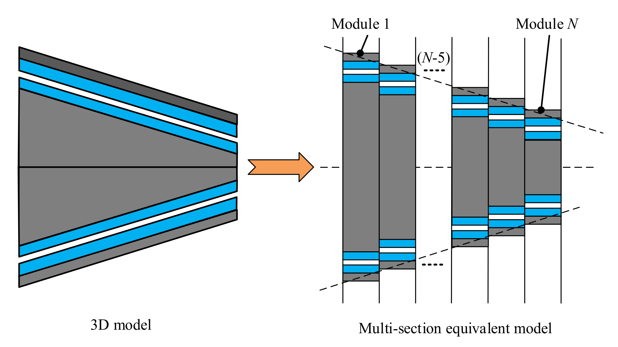
The CPMC can’t directly use a two-dimensional model to simplify the calculation as a traditional cylindrical permanent magnet coupling. However, the three-dimensional analytical model is very complicated because the permanent magnets of the CPMC are irregular in shape. In the calculation of some performances of permanent magnet motors, a multi-section two-dimensional model is used to approximate the three-dimensional model [
19,
20,
21]. Similarly, we establish an equivalent 3D analysis model here by axial segmentation, as shown in
Figure 6. The CPMC is divided into
N modules along the axial direction, and each module is a common cylindrical permanent magnet coupling. The pull-out torque of the CPMC is approximately equal to the sum of the torque generated by the
N modules.
3.2.3. Torque Calculation
The analytical solution of the torque of permanent magnet couplings has been extensively studied For a common cylindrical permanent magnet coupling, the torque can be calculated by Maxwell equation [
8,
14]:
where,
n means the
nth module,
is the deflection angle of internal and external rotors,
is the permeability of vacuum,
is the air gap radius,
is the axial length,
and
are the radial and tangential components of the air gap flux density of the nth module, respectively.
When
N is large enough, the torque of CPMC can be expressed as follows:
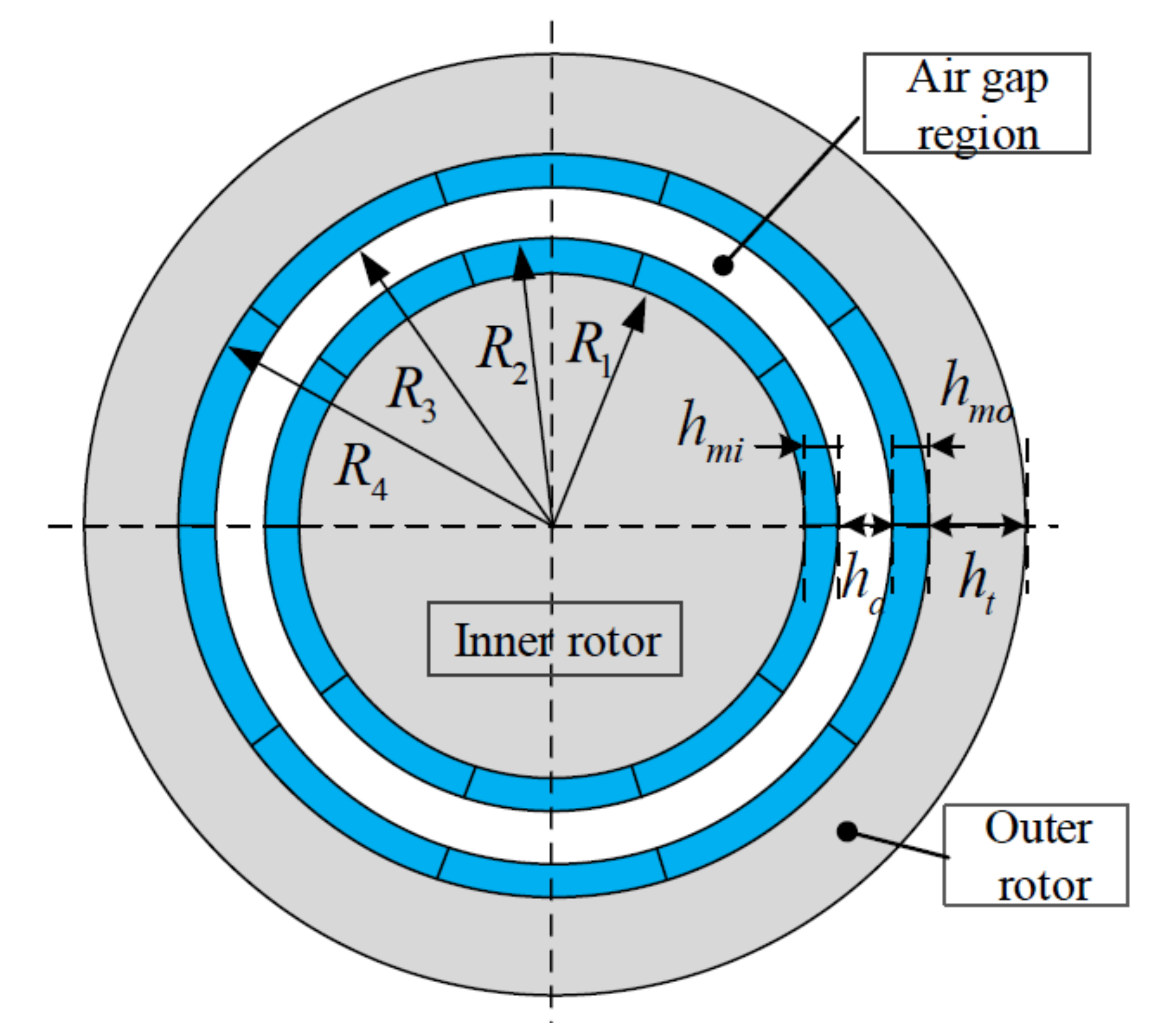
The dimension parameters of cylindrical permanent magnet coupling are shown in
Figure 7. The air gap flux density is jointly excited by the inner and outer rotor permanent magnets, so it can be expressed as:
where,
,
,
,
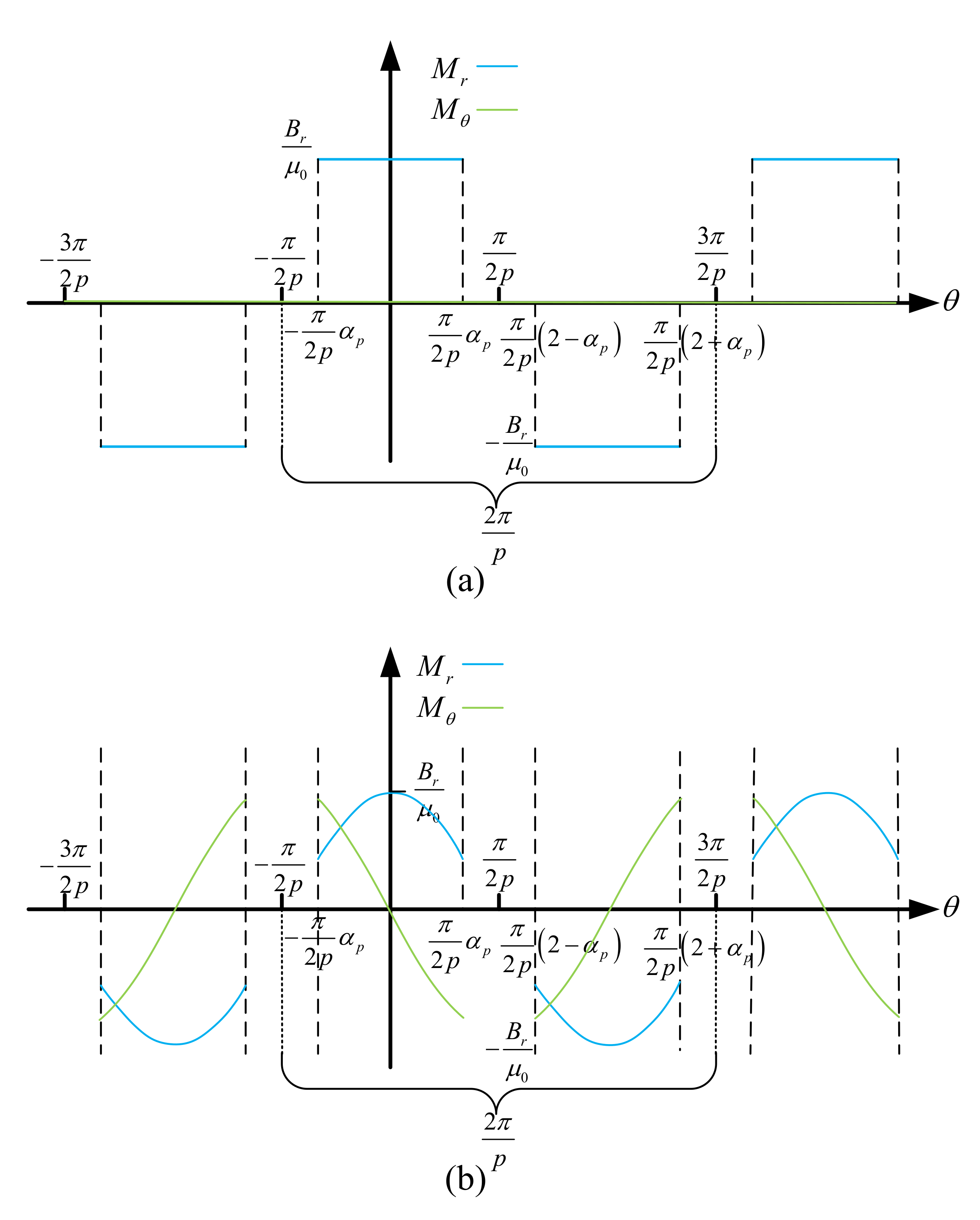
are the radial and tangential components of flux density of the air gap flux density when the inner and outer rotors are separately excited. Each flux density component can be calculated through an analytical method [
22]. When the magnetization mode of the permanent magnets is different, the analytical expression of the magnetization components
and
are different, the waveform is shown in
Figure 8.
The complete solution for the flux density components in the air gap can be deduced from the general solution of Laplacian/quasi-Poissonian equations with specified boundary conditions.
where,
The size parameters are as follows:
3.2.4. Comparison with 3D-FEM
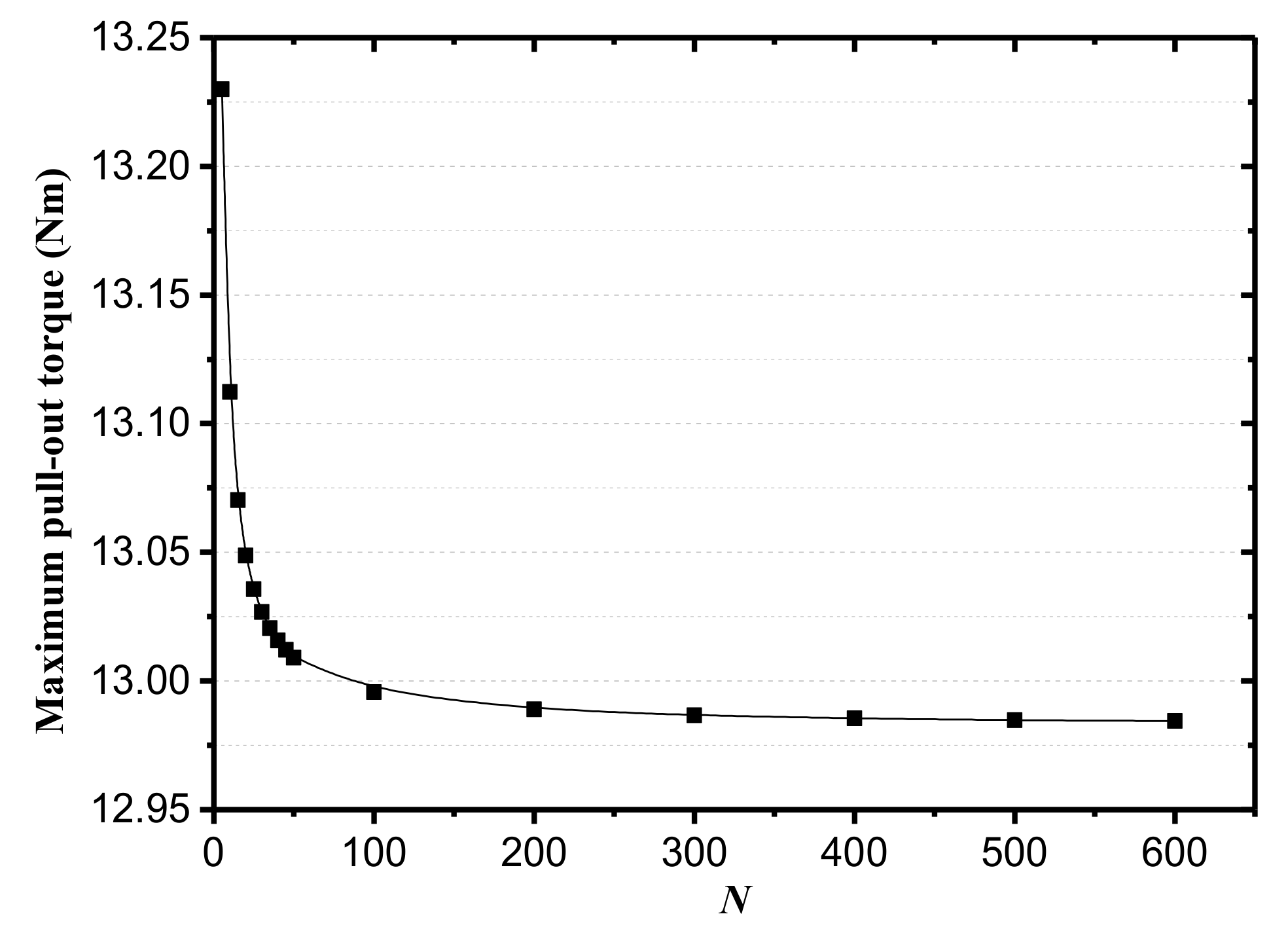
The CPMC is divided into
N modules and the number of
N affects the analytical calculation results. When
N changes from 5 to 600, the maximum pull-out torque of the initially designed CPMC calculated by analytical method is shown in
Figure 9. As can be seen from the figure that
N of 200 and 600 gave substantially the same results. Considering the accuracy and time economy, set
N equal to 200 for the following calculations.
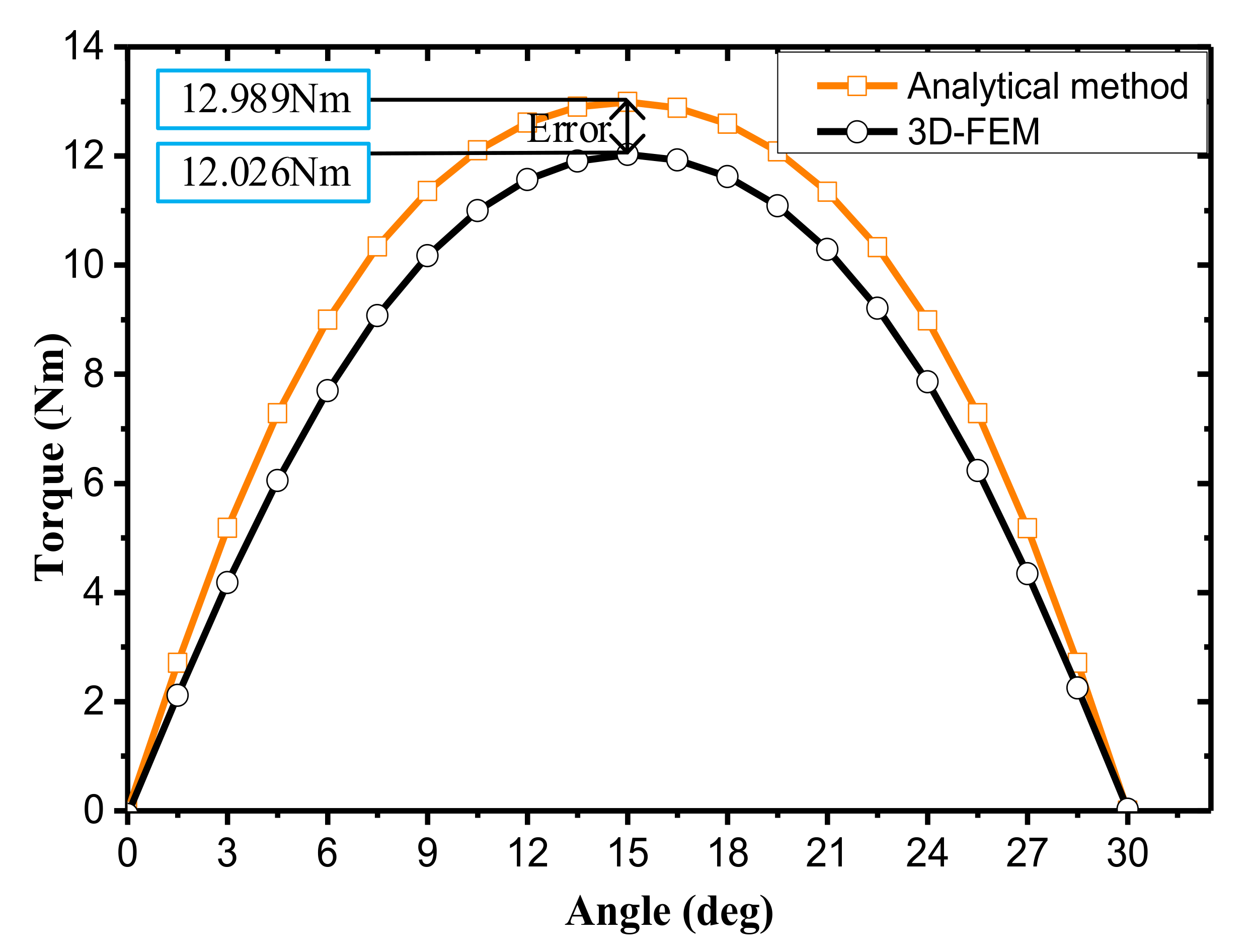
The proposed analytical method and 3D-FEM are used to calculate the pull-out torque of CPMC at different deflection angles, and the pull-out torque curve of half cycle is obtained, as shown in
Figure 10. It can be seen that the torque curve obtained by the two methods have the same trend, and the results calculated by the equivalent three-dimensional analytical method are slightly larger than the 3D-FEM results. When the inner and outer rotor deflection angle is 15°, the maximum pull-out torque is obtained. The relative error between the calculation results of the two methods is 7.4%, which proves the validity and accuracy of the analytical method. The main reason for the error is that the equivalent multi-section method ignores the effects of yoke magnetic field saturation, end effect and magnetic flux leakage.
4. Design Consideration and Optimization
In engineering applications, we most concerned about the maximum transmission torque (
), because it directly determines the power output capability of the propulsion unit. Since permanent magnets are relatively expensive, it is also necessary to increase the
generated by per unit volume of permanent magnets and define the torque density
, as follows:
where,
is the volume of the permanent magnets of CPMC. Considering that the
is very meaningful for making full use of permanent magnets and reducing the cost of CPMC. In the next study, the influence of design parameters on
and
of the initially designed CPMC will be analyzed by equivalent three-dimensional analytical method.
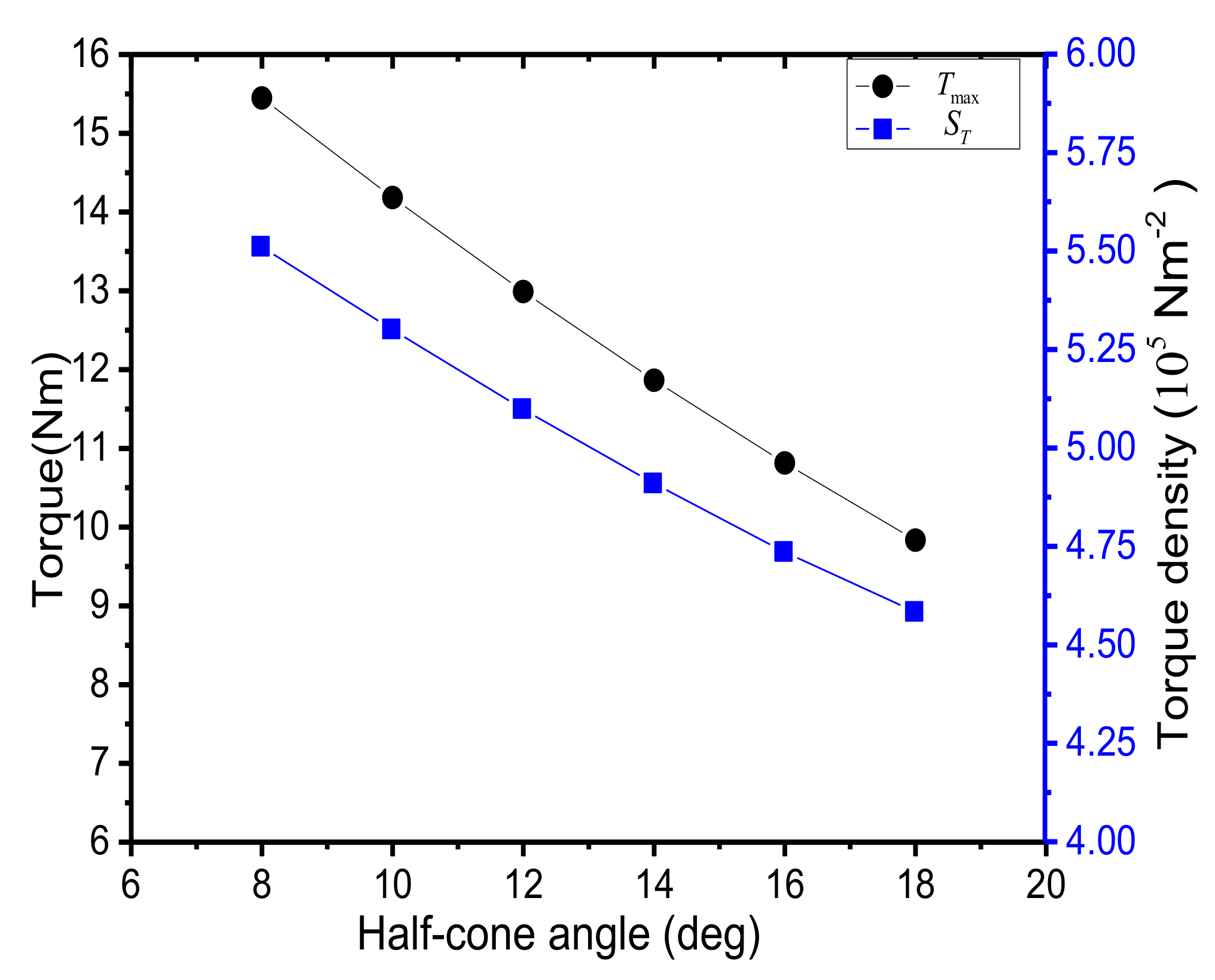
4.1. Influence of Half-Cone Angle
Keeping the diameter of the front end face and axial length unchanged, the variation of the
and
of the CPMC with the half-cone angle is studied by analytical method, as shown in
Figure 11. It can be seen that as the half-cone angle increases, the
and
are continuously reduced. In practical applications, the size of the half-cone angle is often determined by the shape of the tail section of the underwater vehicle.
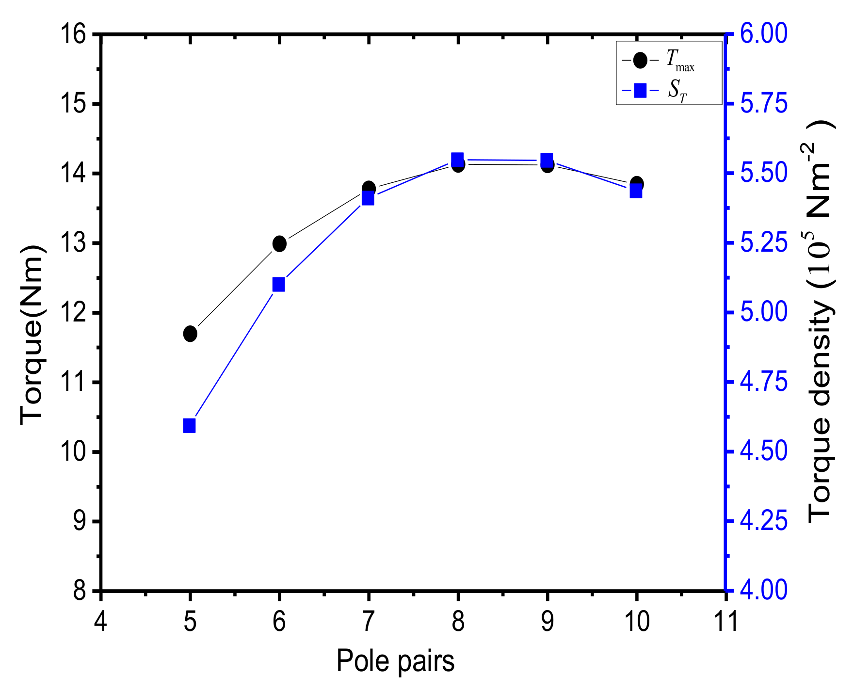
4.2. Influence of Pole Pairs
Keeping the size parameters constant, the
and
of the CPMC versus different pole pairs are calculated with the pole pair increasing from 5 to 10. As shown in
Figure 12, both the
and
increase first and then decrease as the number of polo pairs increases, and have a maximum value when the pole pair is 8.
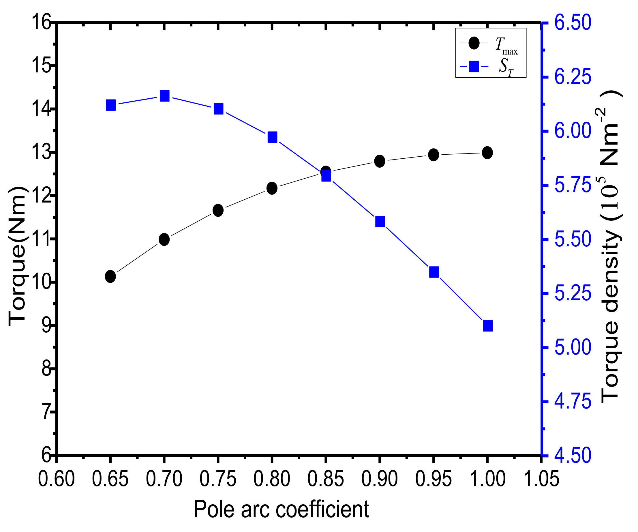
4.3. Influence of Pole Arc Coefficient
The change of pole arc coefficient means a change of the volume of the permanent magnet, and a larger volume of permanent magnets often means a bigger pull-out torque.
Figure 13 shows the variation of
and
versus the pole arc coefficient. The
increases with the increase of the pole arc coefficient, and the
increases first and then decreases as the pole arc coefficient increases, and have a maximum value when the pole arc coefficient is 0.7.
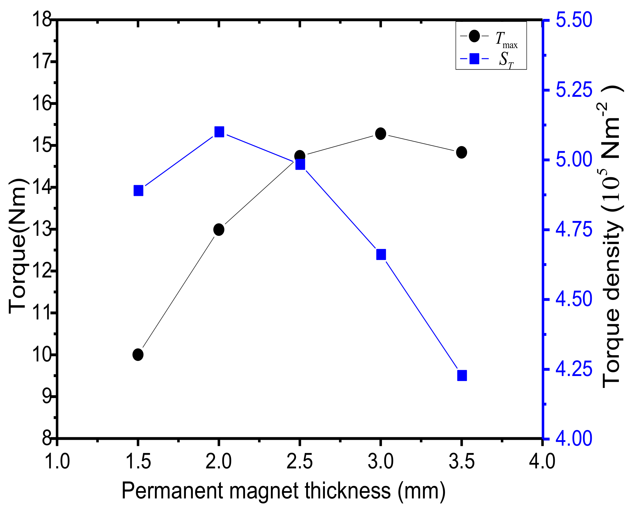
4.4. Influence of Permanent Magnet Thickness
Assuming that the thickness of internal and external permanent magnets is the same, the thickness of rotor yoke is at least 1.5 times that of permanent magnets. Keeping other parameters unchanged, and only changing the thickness of permanent magnet, the variation of
and
are shown in
Figure 14. The maximum value of
and
are obtained with different thicknesses.
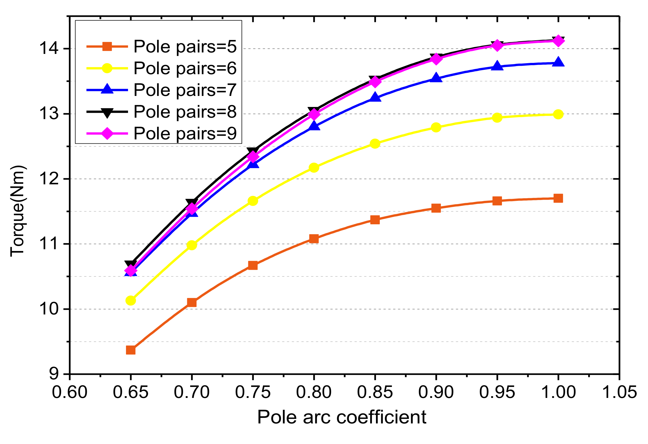
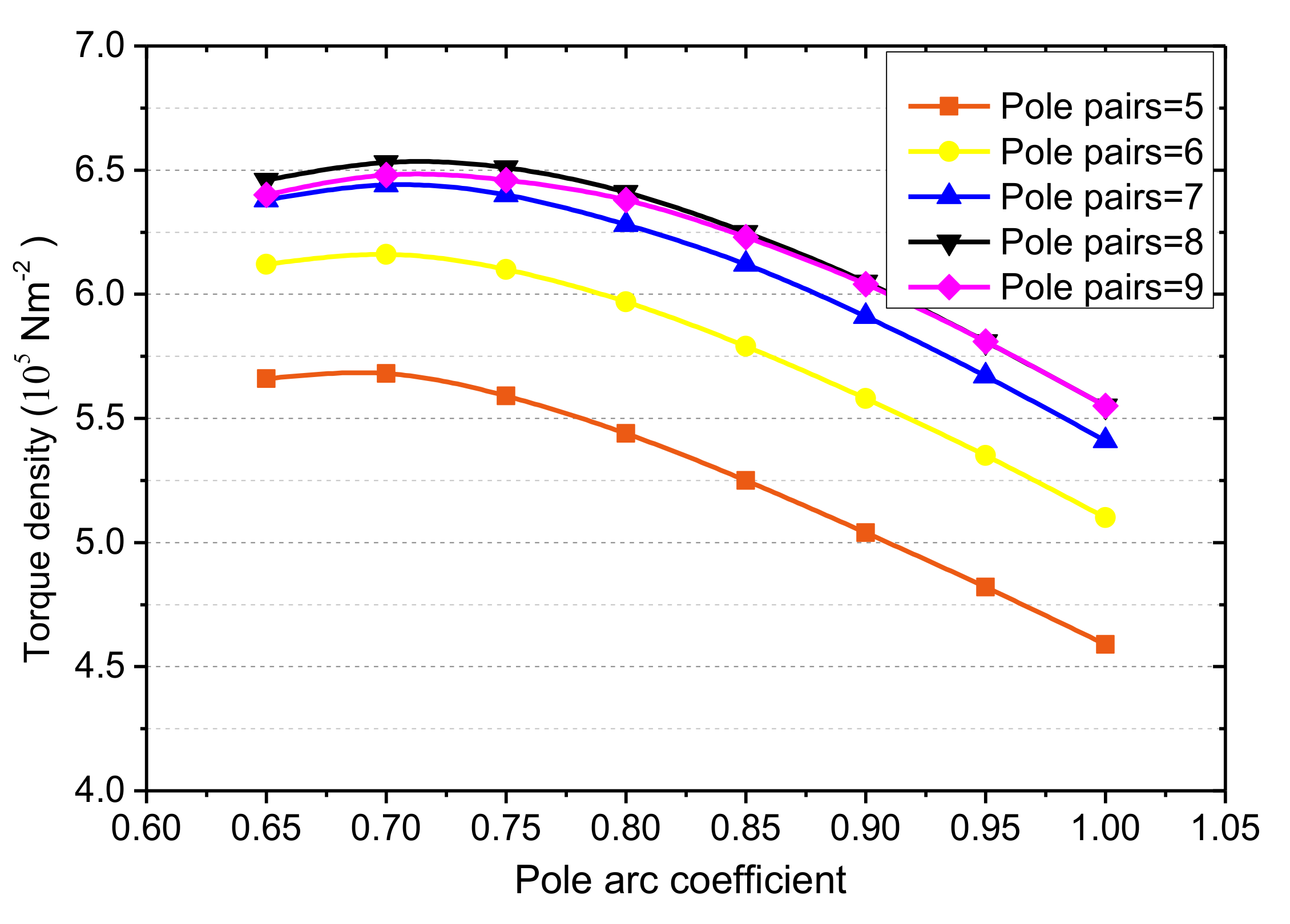
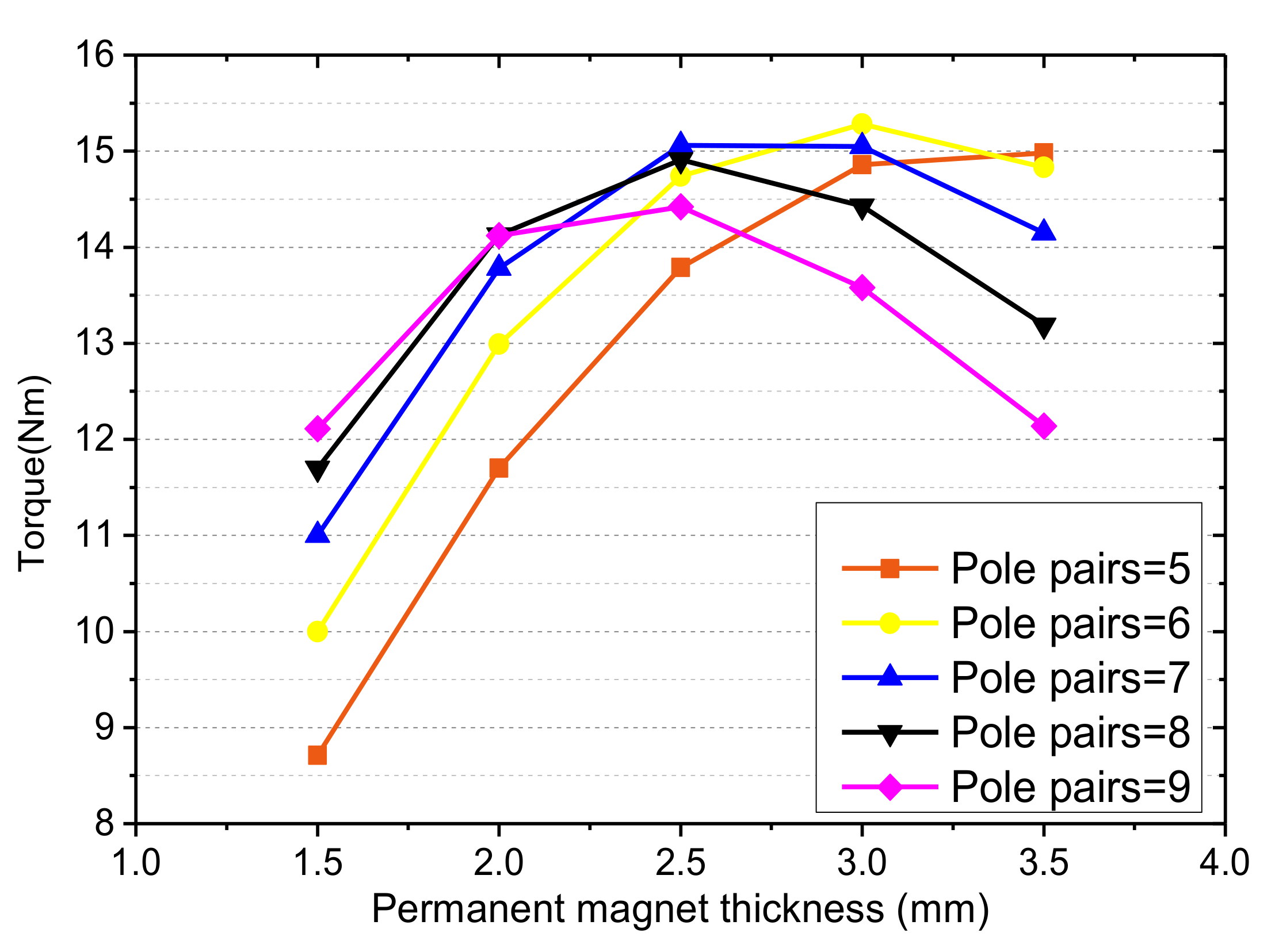
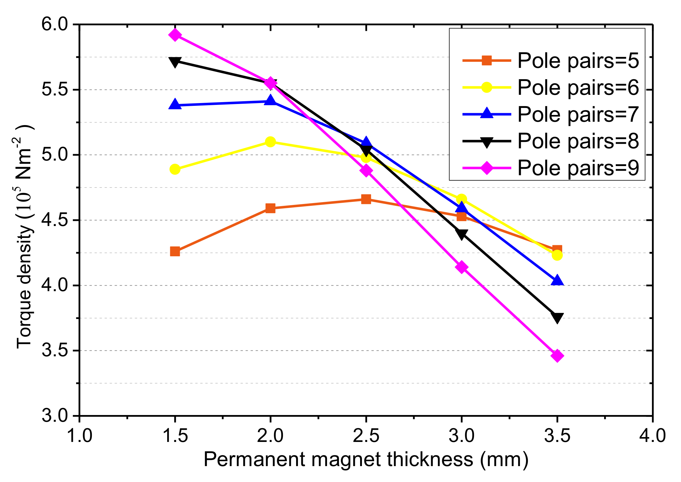
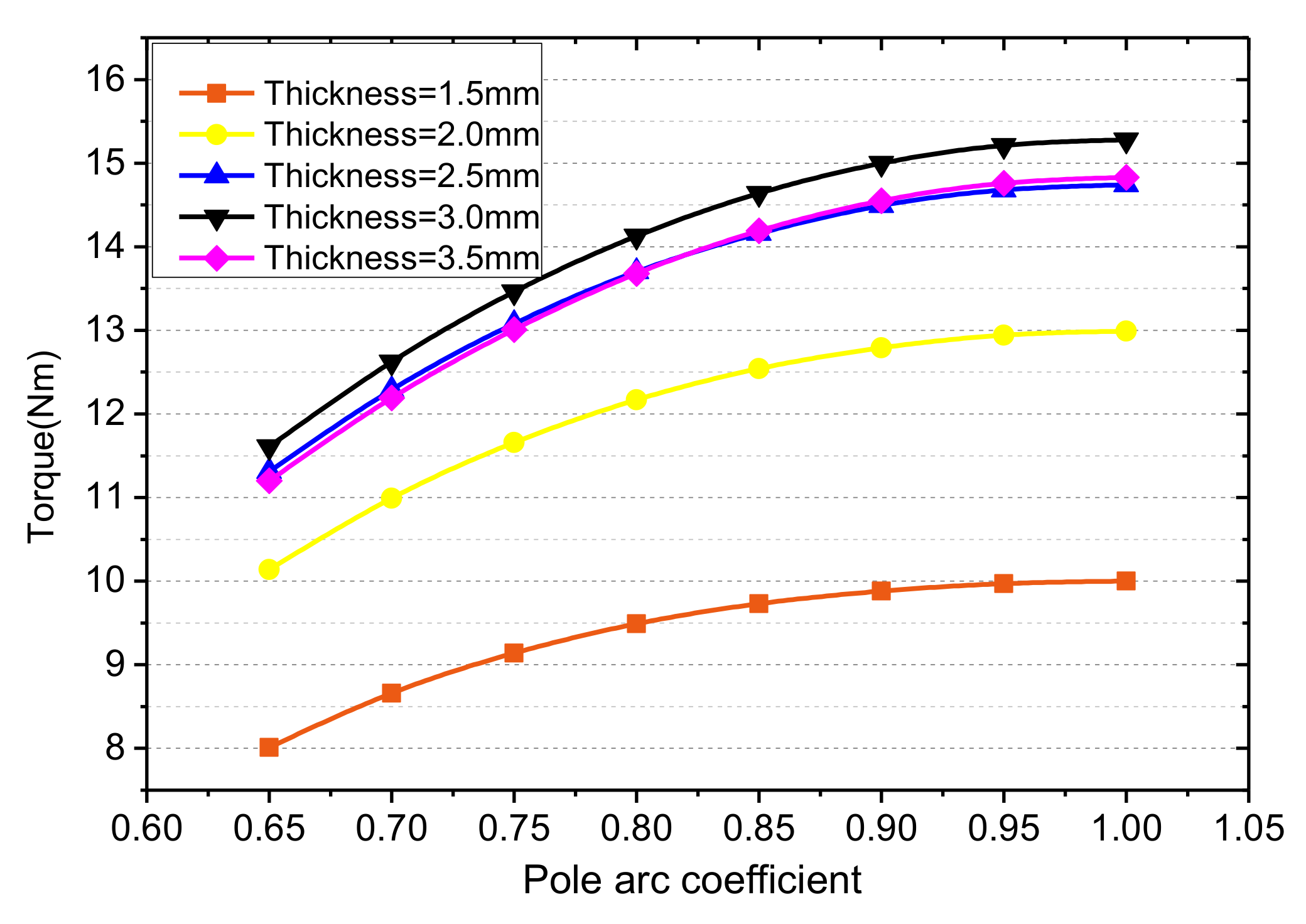
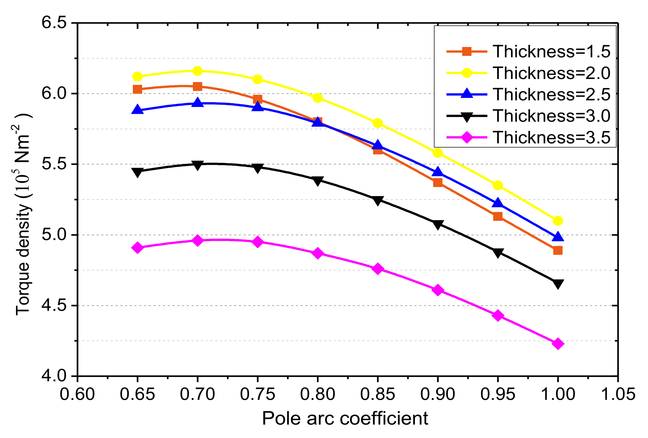
4.5. Interaction Between the Pole Pair, Pole Arc Coefficient and Permanent Magnet Thickness
The half-cone angle of the CPMC designed for underwater propulsion is 12°, which is determined by the vehicle’s profile. The analytical method can be used to analyze the interaction between the pole pairs, pole arc coefficient and permanent magnet thickness (as shown in
Figure 15,
Figure 16,
Figure 17,
Figure 18,
Figure 19 and
Figure 20), which is the basis for the optimal design of CPMC. The pole pair number is a discrete value within a limited range and determining the pole pair in advance can simplify the optimization process.
It can be seen from the figures below that under different pole arc coefficients, the CPMC with a pole pair of 8 always has the maximum and . The CPMC with a pole pair of 8 also has good performance at different permanent magnet thickness. Hence, for the CPMC studied in this paper, the pole pairs be 8 is more suitable for further study. Then, the CPMC optimization design problem can be simplified to an optimization problem of two independent variables the permanent magnet thickness and the pole arc coefficient .
4.6. Preliminary Optimization Design
In this paper, the non-dominated sorting genetic algorithm-II (NSGA-II) was utilized to solve the multi-objective optimization of CPMC. NSGA-II is one of the most widely used multi-objective optimization algorithms, which has the characteristics of high efficiency, minimum user interaction, solutions uniformly distributed and so on [
23,
24].
Generally, NSGA-II is a method of searching for the Pareto optimal solutions according to several certain known models (surrogate models). In this paper, these surrogate models are established by using Kriging method, such as maximal pull-out torque (
) and torque density (
). The constraint conditions were given based on the actual size of the CPMC. The multi-objective function could be defined as:
NSGA-II could find a set of Pareto optimal solution and corresponding design parameters of the CPMC.
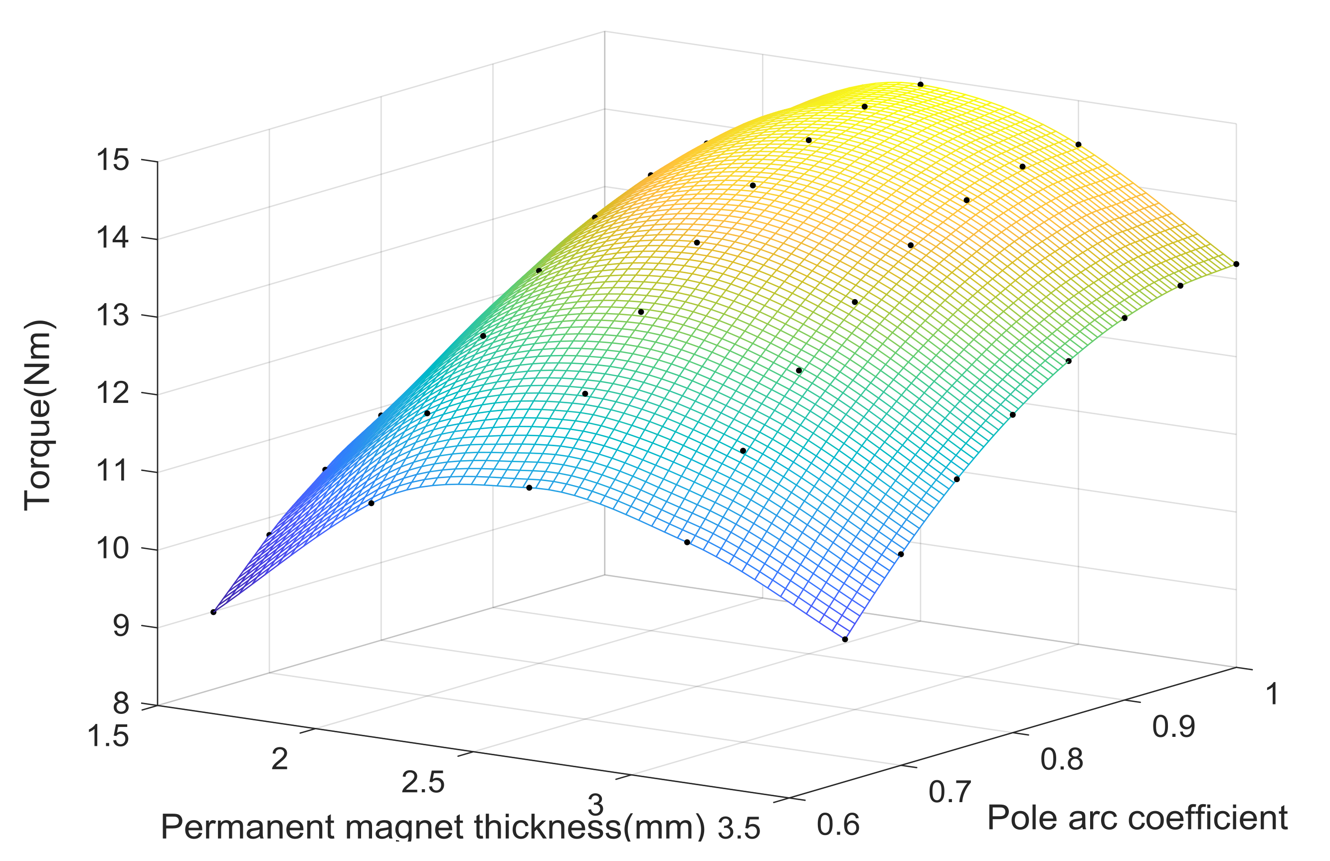
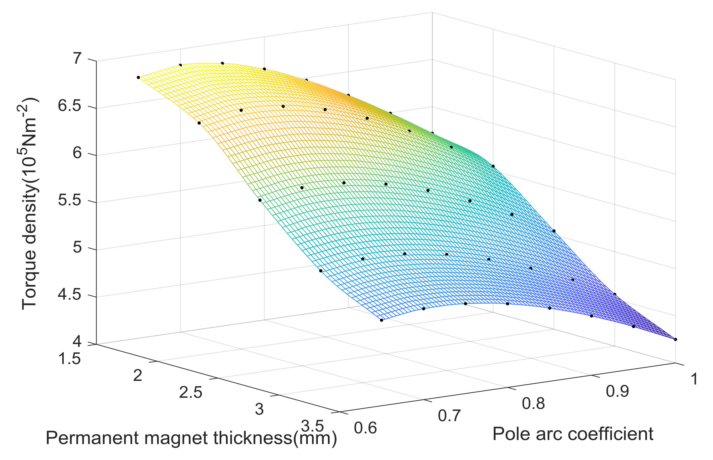
The
changes from 1.5 mm to 3 mm with a 0.5 mm interval and the pole arc coefficient
changes from 0.65 to 1.0 with a 0.05 interval. 40 samples were analyzed by using the equivalent three-dimensional analytical method. The objective
and
is shown in
Table 2 and
Table 3. The response surfaces of two sub objective function are built as shown respectively in
Figure 21 and
Figure 22.
The optimization procedure uses 100 individuals evolving during 50 generations, the mutation probability is 0.05, and the recombination probability is 0.5.
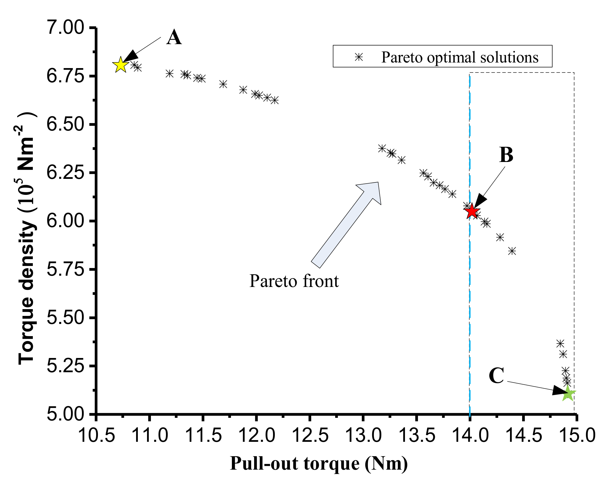
Figure 23 shows the Pareto front of the maximum pull-out torque and torque density of CPMC. The points A and C are the optimum design points which can be obtained by single-objective optimization. For the CPMC, it is necessary to achieve a given pull-out torque, while making the torque density as large as possible. Setting the pull-out torque to 14 Nm, the optimum design points is marked with the red five-pointed star B. The optimum design parameters and objective values obtained by NSGA-II are shown in
Table 4. The pull-out torque of the preliminary optimized model is improved by 17.545% and the torque density increased from
to
when compared with that of the initially designed CPMC.


