Article

Influence of Central Platform on Hydrodynamic Performance of Semi-Submerged Multi-Buoy Wave Energy Converter

1
College of Mechanical and Energy Engineering, Jimei University, Xiamen 361021, China
2
Key Laboratory of Energy Cleaning Utilization and Development of Fujian Province, Xiamen 361021, China
3
Key Laboratory of Ocean Renewable Energy Equipment, Xiamen 361021, China
*
Author to whom correspondence should be addressed.
J. Mar. Sci. Eng. 2020, 8(1), 12; https://doi.org/10.3390/jmse8010012
Submission received: 27 November 2019 / Revised: 6 December 2019 / Accepted: 12 December 2019 / Published: 23 December 2019

Abstract

:
The influence of the central platform on hydrodynamic performance of a wave energy converter (WEC) has remained elusive. To approach this dearth of relevant theoretical research, this paper presents a semi-submerged multi-buoy WEC and the results of the numerical analysis at different dimension parameters of the central platform of the WEC. The WEC consists of three oscillating buoys hinged with a central platform through multiple actuating arms. Numerical analysis revealed that there exists a relationship between the hydrodynamic performance of device and the geometry of the central platform. At the given wave condition, different central platform size would obviously affect the hydrodynamic performance and wave energy capture width ratio of the semi-submerged multi-buoy WEC. Additionally, appropriately increasing central platform draft would help to improve the wave energy capture capability of the oscillating buoys.

1. Introduction

Due to the urgency to act against climate change caused by the growing carbon dioxide in the atmosphere, renewable energy has received extensive attention around the world [1]. Wave energy is the integration of kinetic and potential energy of a water point relative to displacement of hydrostatic surface [2]. Compared to traditional energy sources, it produces fewer waste products such as chemical pollution and carbon dioxide, which means the negative influence upon the environment is minimal. The research on wave energy conversion started in the 1970s when the oil crises provoked the exploitation of a wide variety of renewable energy sources. An advantage of wave energy technology is the wide diversity of design concepts. Different technologies use different solutions to harness energy from sea waves and are suited to operate at different water depths and locations [3]. A multi-buoy wave energy converter (WEC) primarily consists of three parts: a central platform, multiple oscillating bodies, and multiple actuating arms [4]. Additionally, the multi-buoy WEC can be classified into three types: stationary type, floating type, and semi-submerged type.
First proposed in 2000 by Niels and Keld Hansen, the stationary type WEC, Wavestar has become one of the world-leading wave energy technologies [5], which generates electricity through the oscillatory motion of hemispherical floats which in turn drive hydraulic power take-off systems. Kramer, who has already investigated the effect of a hydraulic power take-off system on device efficiency, found that power conversion efficiencies could improve by 70% by using the hydraulic system proposed in the paper [6]. Additionally, Kramer also presented a reliability-based structural optimization of the Wavestar WEC, which focused on improving the reliability of the device [7], which presented how structural designs of WECs can be optimized by using a reliability-based approach, and the ultimate goal is also to improve the energy efficiency and life of the device. However, the Wavestar WEC is fixed on the seabed which results in the water depth in the installation area being limited.
For the floating type WEC, our research group already has built two multi-buoy WEC, which are called “JMU I” and “JMU II”, respectively. Both of them have a floating structure, but the former uses a mechanical energy conversion system, while the latter is a hydraulic system [8]. In [9] the authors investigated influence of buoy placement and platform wedge angle on hydrodynamic characteristics of the “JMU II”, and the results show that different buoy placements and platform wedge angles would affect the amplitude of buoys. However, the investigation of the platform in the paper was limited to the platform wedge angle. Additionally, for the floating type WEC, the central platform has a shock amplitude of oscillation, which means it would indirectly affect buoy oscillation and also reduce the efficiency of wave energy collection.
For the semi-submerged multi-buoy WEC, the Guangzhou Institute of Energy Research of the Chinese Academy of Sciences successfully launched the two Eagle-type wave power generation equipment “Eagle I” and “Wanshan” in the waters of Wanshan Island, Zhuhai City, which is a semi-submerged barge and wave energy capture equipment [10,11]. The combination body can be parked like a ship, or can dive to a designated position to become a wave energy generating device. The “eagle” floating body used in the device is an improved type of “nodding duck” WEC. In [12], the frequency domain motion simulation of the “Eagle I” WEC under different wave elements and different PTO (power take-off) damping is presented, and the optimal load damping is obtained, which provides the theoretical basis for load design of prototype device. Additionally, the authors of [13] introduced the sea trial data of “Eagle I”, and the experimental results verified the feasibility of the WEC. The “Wanshan” WEC is an improved model of the former, and its installed power could reach 100 kW which is 10 times of the former model. In [14] the authors investigated the hydrodynamic characteristics of a sharp eagle WEC, which could be considered that the buoy of the device is almost as same as “Wanshan”, and the result shows that eagle head power prime mover has a strong ability to capture wave energy. In [15] the authors systematically introduced the structure, working principle, and experimental data of the sea trial of the device. It can be seen that the buoys of the device have been optimized, but the influence of the central platform on wave energy conversion efficiency of the device has not been mentioned.
To date, most of the studies are limited to the influence of the arrangement, numbers, and structure of the buoy, and the energy load damping on the efficiency of the device. As far as we know, the influence of the central platform on hydrodynamic performance of WEC have remained elusive. Hence, this paper presents a semi-submerged multi-buoy WEC, which uses the relative motion between buoys and central platform to drive the hydraulic system, such that the WEC could transfer wave energy to hydraulic power and be further utilized. Compared with other WECs, the presented WEC is proven to have higher sea condition adaptability due to the semi-submerged structure and energy output is more stable by using the hydraulic system. The authors of [16] have already analyzed the influence of buoys on hydrodynamic performance of the WEC, which shows the geometry of buoys would affect the wave energy capture width ratio of the WEC. The emphasis of this paper is to analyze the influence of the central platform on hydrodynamic performance and wave energy capture ratio of the WEC, which may provide a new strategy to increase wave energy conversion efficiency of multi-buoy WEC.

2. Materials and Methods

2.1. Methods

The dynamic equation of motion in the frequency domain can be written as [17]:
ω 2 M a + M i ω C d + C P T O + K S + K P T O A J T A J 0 X F J = F e 0 ,
where F e and X are the frequency dependent complex amplitude of wave force array and complex amplitude of corresponding displacements array, respectively; M is the structure mass matrix for the central platform; M a and C d are the hydrodynamic added mass matrix and the hydrodynamic damping matrix, respectively; K S is the hydrostatic restoring matrix; C P T O and K P T O are the PTO (power take-off) system damping and stiffness matrices, respectively; A J is the displacement constraint matrix; F J is the joint force vector; and F e   , M a , and C d can be obtained by solving the wave diffraction and radiation problem by using a boundary element method (ANSYS-AQWA).
To simplify the numerical simulation, a time domain analysis is carried out with a linear PTO. The basic equation of structural motion in the time domain can be written as [18]:
M + M x ¨ t + t C t τ x ˙ τ d τ + K s x t + F j o i n t t + F P T O t = F e x c t ,
where M is the hydrodynamic added mass matrix for ω   ; x t , x ˙ t and x ¨ t are the generalized displacement, velocity and acceleration vectors in the time domain, respectively; C t is the retardation function matrix; F j o i n t t is the resistant force vector due to the joint connection; F P T O t is the resistant force vector due to the PTO system, which is the hydraulic system damping in this paper and in order to simplify the numerical simulation, the F P T O t is constant.

2.2. Model of the WEC

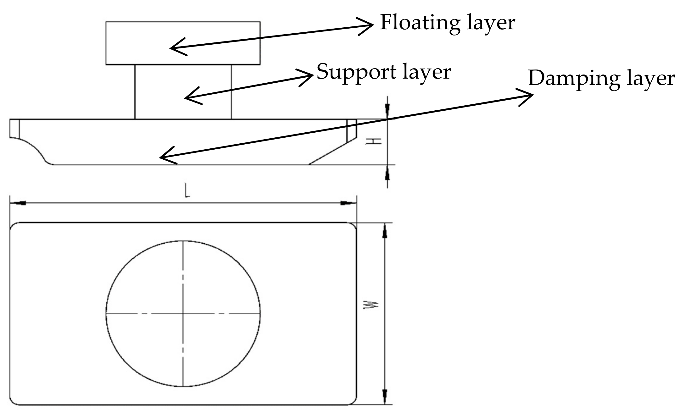
A three-dimensional model of the full-size device was established using SolidWorks. The semi-submerged multi-buoy WEC proposed in the paper is composed of three oscillating buoys, a central platform, three actuating arms, and hydraulic systems at the joint as illustrated in Figure 1, which was built according to the original proportion of the solid model. The angle between the buoys is 120°, and Buoy 1 is located at the bow of the floating platform, Buoy 2 and Buoy 3 are symmetrically distributed on both sides of the central platform. The central platform can be divided into three layers: damping layer, support layer, and floating layer, as shown in Figure 2, which also presents the dimension of central platform: where H is the height of the damping layer, L is the length of the damping layer, and W is width of the damping layer. In addition, the initial parameters of the damping layer and buoys are presented in Table 1. The device has the capability of autonomous navigation with the buoys at the top of the central platform. Additionally, when it has arrived at the specified sea area, the central platform ballast tank injects seawater to sink the hull, after that buoys would descend to the surface of the sea. As the wave passed down the WEC, the oscillating buoys and central platform make a relative motion around the joint. This wave induced relative motion of the rafts is resisted by hydraulic systems. The hydraulic cylinders pump the high-pressure fluid via smooth gas accumulators to the hydraulic motor, which could be further utilized. This paper mainly investigates the hydrodynamic performance of the WEC under different geometry parameters of the damping layer and the draught depth of the central platform.
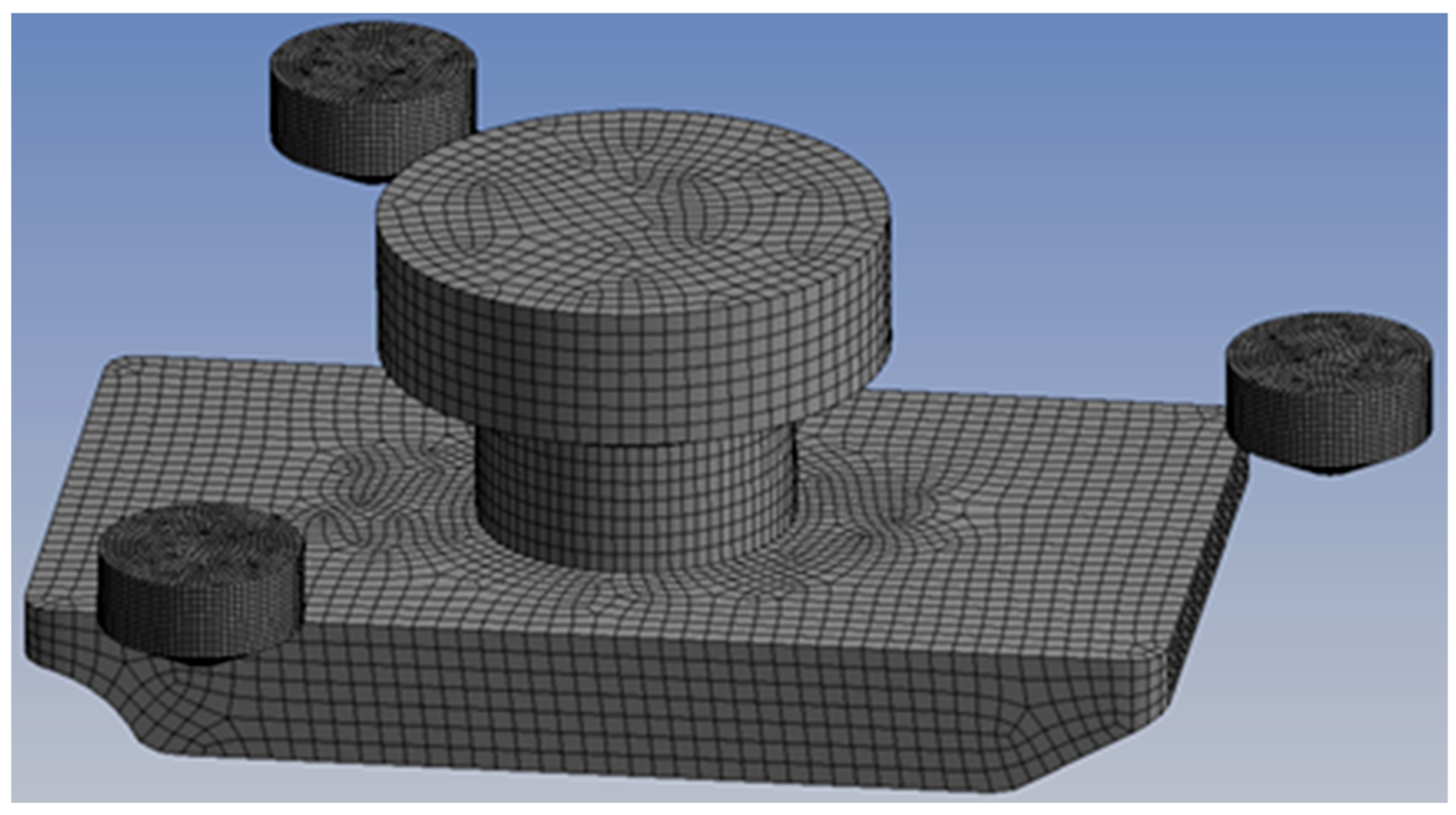
In the numerical calculation, we used the ANSYS-AQWA for simulation, which is based on potential flow theory and boundary elements method. Additionally, before running the simulation, the outside surface of the WEC model is divided into meshes, as shown in Figure 3, and the sea state parameters are set to water depth of 15 m and sea area of 100 m2. The maximum grid size of the central platform and buoys are 0.6 and 0.2 m, respectively. For the sea state parameters setting of the time domain calculation, which refer to the sea conditions of the sea trial experiment, the wave height is 1 m, the period is 3 s, and the direction is pointed by the bow to the stern. The hinge damping of the buoys and central platform is set to 3000 (N*m/(°/s)), the additional damping parameter is set to 3500 (N/(m/s)), and the additional damping is intended to simulate the damping force of the hydraulic system of the device. The simulation time is set as 120 s, and the time step is 0.1 s.

3. Results of the Numerical Analysis

In this section, we investigate the hydrodynamic performance of the device in different damping layer aspect ratios, cross-sectional areas, heights, and drafts of the central platform. In addition, the hydrodynamic performance of the central platform and the instantaneous power curves of the buoys are shown in each section. Since Buoy 2 and Buoy 3 are symmetrical at the platform in the wave direction, both of them have the same hydrodynamic performance. Therefore, only the simulation results of Buoy 2 are presented in this paper.

3.1. Numerical Results at Different Aspect Ratio of the Damping Layer

3.1.1. Hydrodynamic Performance of the Central Platform

The aspect ratio of the damping layer could be obtained by dividing the damping layer lengths (along the wave direction) L by its width (at a 90° angle to the direction of the wave) W, which can use B to represent:
B = L/W.
The influence of a different aspect ratio on hydrodynamic performance is examined with five different B values, ranging from 1 to 2.69. Additionally, the values of the B in each computation is presented in Table 2. The other parameters used are the initial parameters in this simulation.
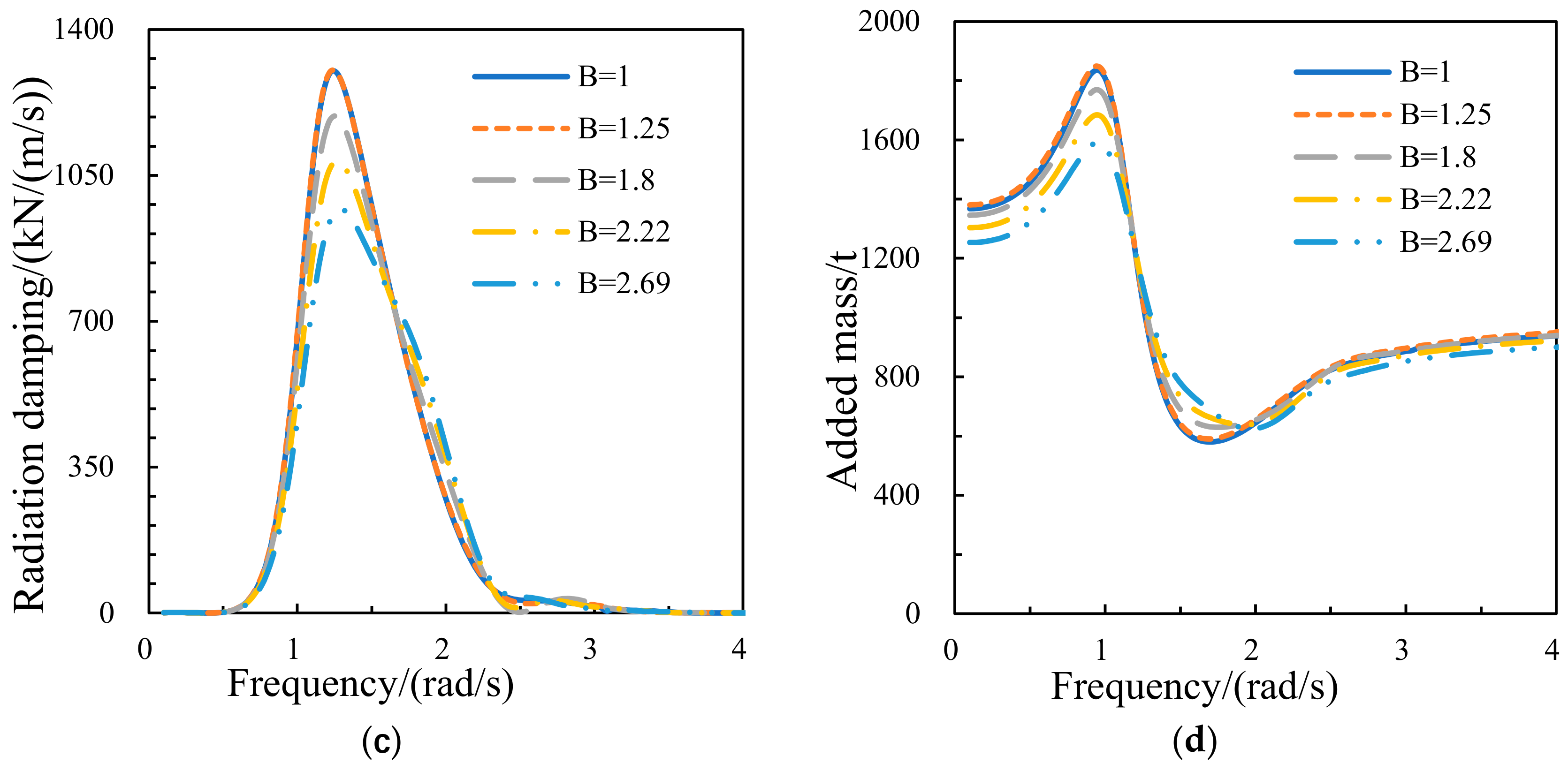
Figure 4 shows the hydrodynamic performance curves of the central platform, it can be seen that wave force, diffraction force, and radiation damping all decrease with the increase of aspect ratio of the damping layer. For the wave force and the diffraction force, the maximum value occurs when the wave frequency is around 1.1 rad/s; for the radiation damping, the maximum value occurs when the wave frequency is around 1.3 rad/s; and for added mass, the maximum value occurs when the wave frequency is around 1 rad/s; which means that when the aspect ratio changes, the wave frequency at the peak of the curves are not changed. The added mass is decreased with the aspect ratio increases, except that the wave frequency is in the range of 1.2–2 rad/s.
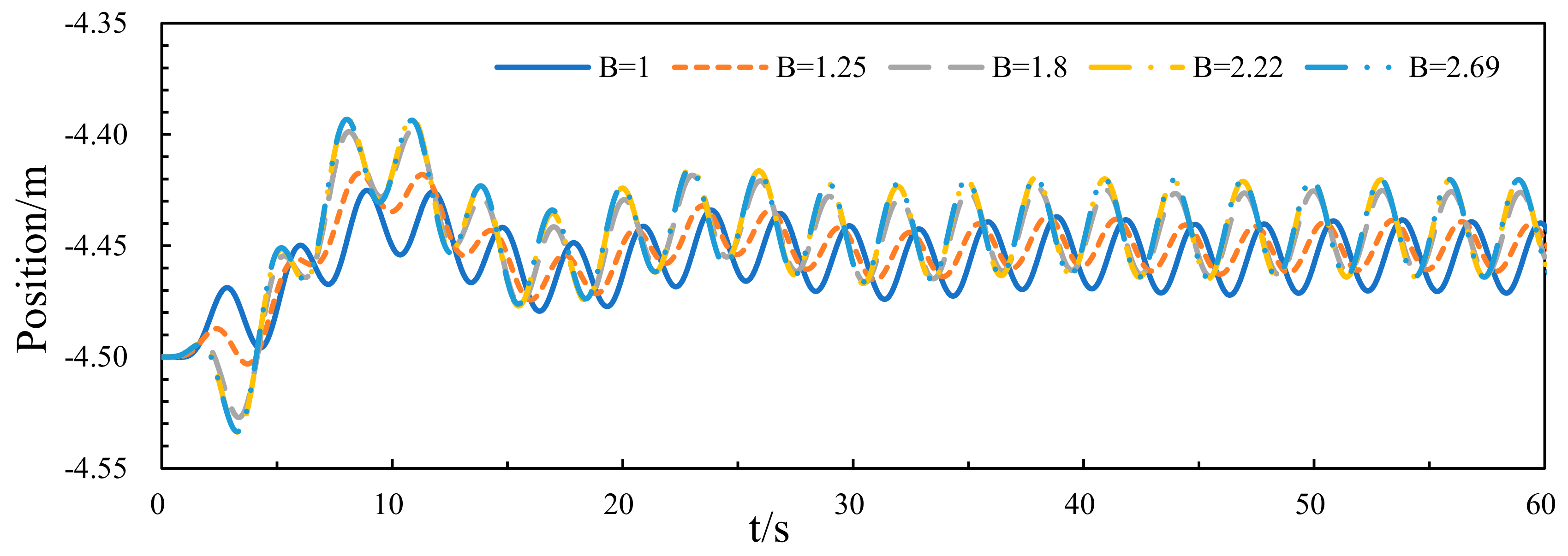
Figure 5 shows the oscillation curves of the central platform, which indicated that when the aspect ratio of damping layer is 1.25, the central platform has the smallest oscillation amplitude. However, the difference in oscillation amplitude of the central platform is small under different aspect ratios, which means the aspect ratio of the damping layer has little effect on the platform oscillation.

3.1.2. Wave Energy Capture Width Ratio of the Device

To better reflect the hydrodynamic performance of a WEC, capture width ratio is mentioned, which is a measure of the hydrodynamic efficiency [19]. It is obtained by dividing the absorbed wave power P by wave resource J and characteristic dimension D:
η = P/JD,
where P is the absorbed wave power, which could be obtained by the instantaneous power curves of the buoys; and for the device presented in the paper, D is the diameter of buoy. As for J, it can be shown as [20]:
J = (ρg2)/32πH2T,
where ρ is the density of sea water which is 1025 kg/m3; the gravity g is 9.81 m/s2; H and T are the height of wave and period of wave, respectively.
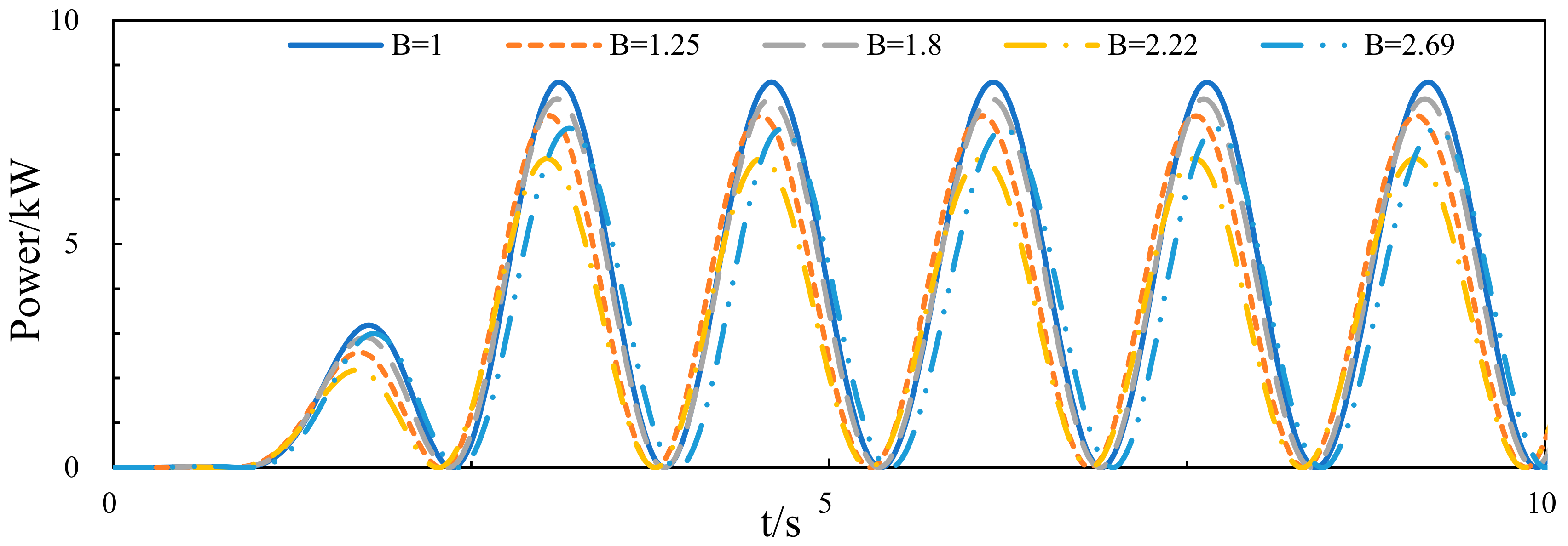
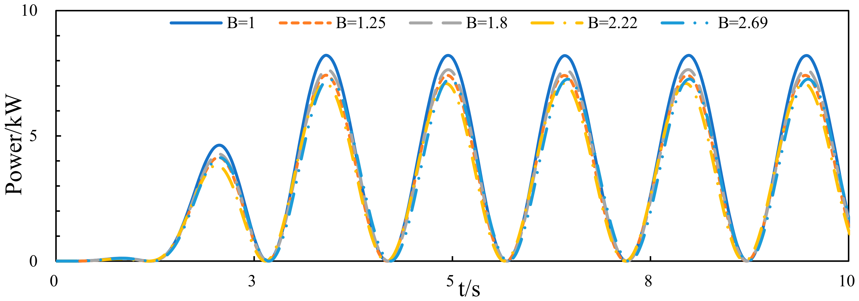
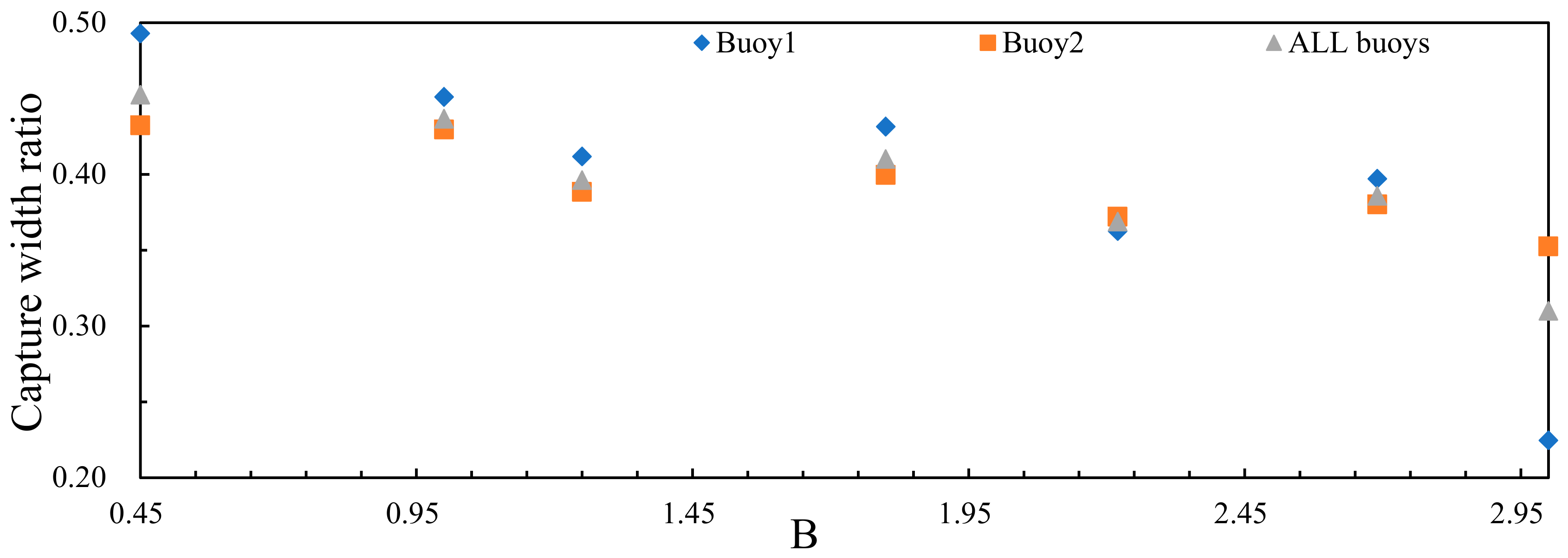
Figure 6 and Figure 7 show the instantaneous power curves of Buoy 1 and Buoy 2, respectively. It can be seen that the maximum value of instantaneous power of Buoy 1 is 8.6 kW when the aspect ratio is 1 and the minimum value occurs when the aspect ratio is 2.22, which is about 7 kW. For Buoy 2, the maximum value is 8.2 kW when the aspect ratio is 1 and the minimum value is 6.8 kW when the aspect ratio is 2.22. Figure 8 is the curve of capture width ratio with aspect ratio, which shows the capture width ratio of the device generally decreases as the aspect ratio of the damping layer increases. In order to better show its regularity, two sets of simulation data were added in the process of drawing the curve, which are B = 3 and B = 0.45, respectively (L/W are 23.2/7.7 and 9/20, respectively). At a lower aspect ratio, the capture width ratio of Buoy 1 is better than Buoy 2, and the difference is narrowed as the aspect ratio increases. The capture width ratio of all buoys refers to the average wave energy capture width ratio of three buoys. However, when the aspect ratio of the damping layer is further increased, the wave energy flowing through Buoy 1 is consumed too much by the damping layer, resulting in a rapid decrease in the capture width ratio.
The above results show that appropriately reducing the aspect ratio of the damping layer of the central platform is beneficial to increasing the wave energy capture width ratio of the device, which could improve the wave energy collection efficiency.

3.2. Numerical Results at Different Areas of the Damping Layer

3.2.1. Hydrodynamic Performance of the Central Platform

The area of damping layer refers to L multiplied by W, which can use S to represent:
S = LW.
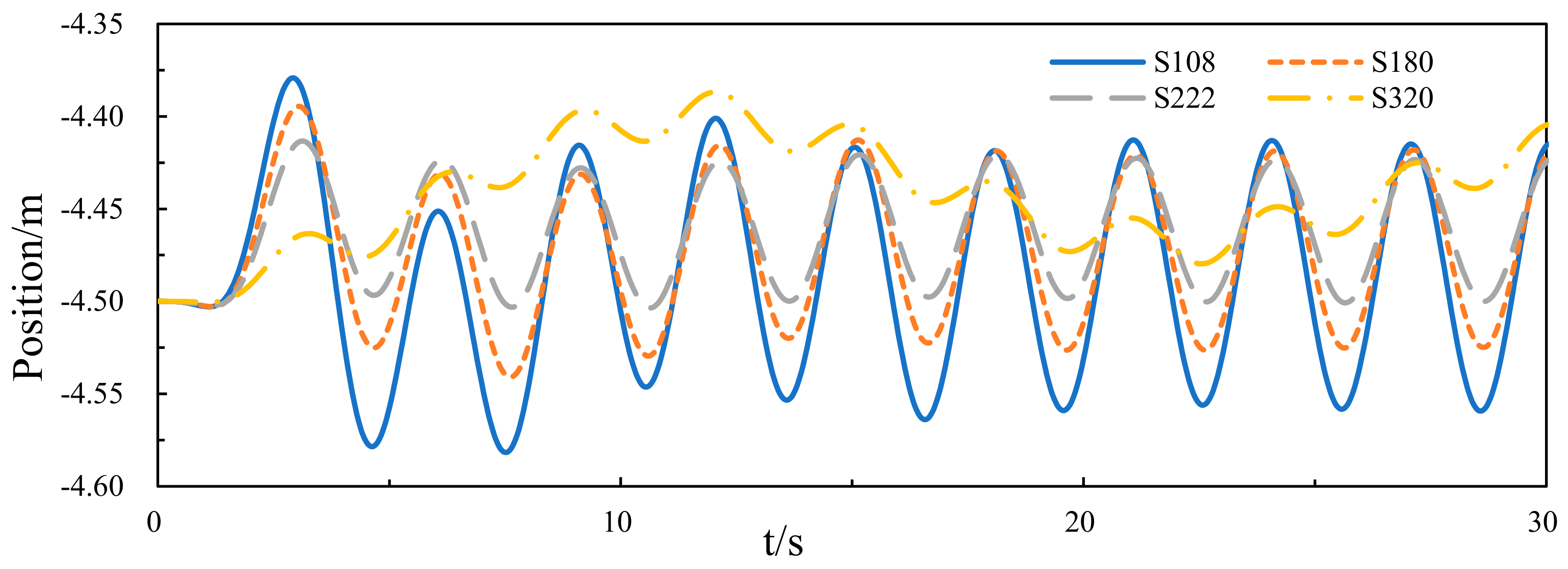
The influence of different areas on hydrodynamic performance is examined with four different S ranging from 108 to 320 m2. As we considered, the wave energy collection efficiency is better when the aspect ratio of the damping layer is 0.45. Hence, in this simulation when the S varies, B remains at 0.45. Additionally, the values of S in each computation is presented in Table 3. The other parameters use the initial parameters in this simulation.
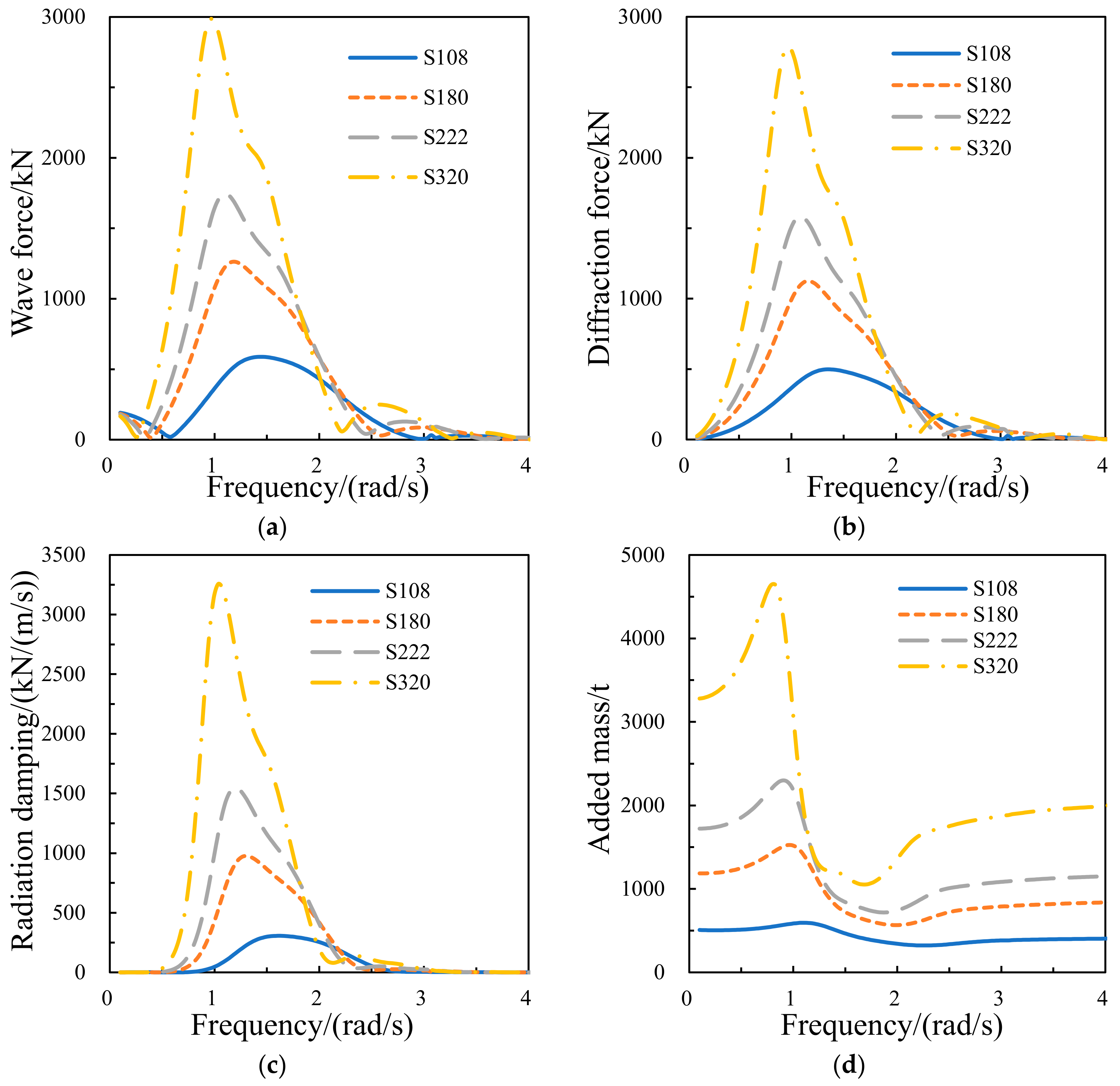
Figure 9 shows the hydrodynamic performance curves of the central platform, and it can be seen that wave force, diffraction force, radiation damping, and added mass all increase with the increase in area of the damping layer. For the wave force, the diffraction force, the radiation damping, and added mass, the range of wave frequency corresponding to the peak value of the curve is between 0.95–1.45, 0.95–1.34, 1.03–1.5, and 0.83–1.14 rad/s, respectively, which means the wave frequency at the peak of the curves decreases slightly with the increase in the area of the damping layer.
Figure 10 shows the oscillation curves of the central platform, which indicated that when the area of damping layer is 222 m2, the central platform has the smallest amplitude of oscillation, and the difference in oscillation amplitude of the central platform is obvious under different areas of the damping layer, which means the area of the damping layer has great effect on the platform oscillation. Additionally, it can be seen that when the area of the damping layer is 320 m2, the oscillation of the central platform is not transient, which is due to large area and low aspect ratio of the damping layer, resulting in excessive platform roll. In addition, the curve is based on the mass point of the central platform, and the excessive platform roll would result in volatility of the oscillation of the central platform.

3.2.2. Wave Energy Capture Width Ratio of the Device

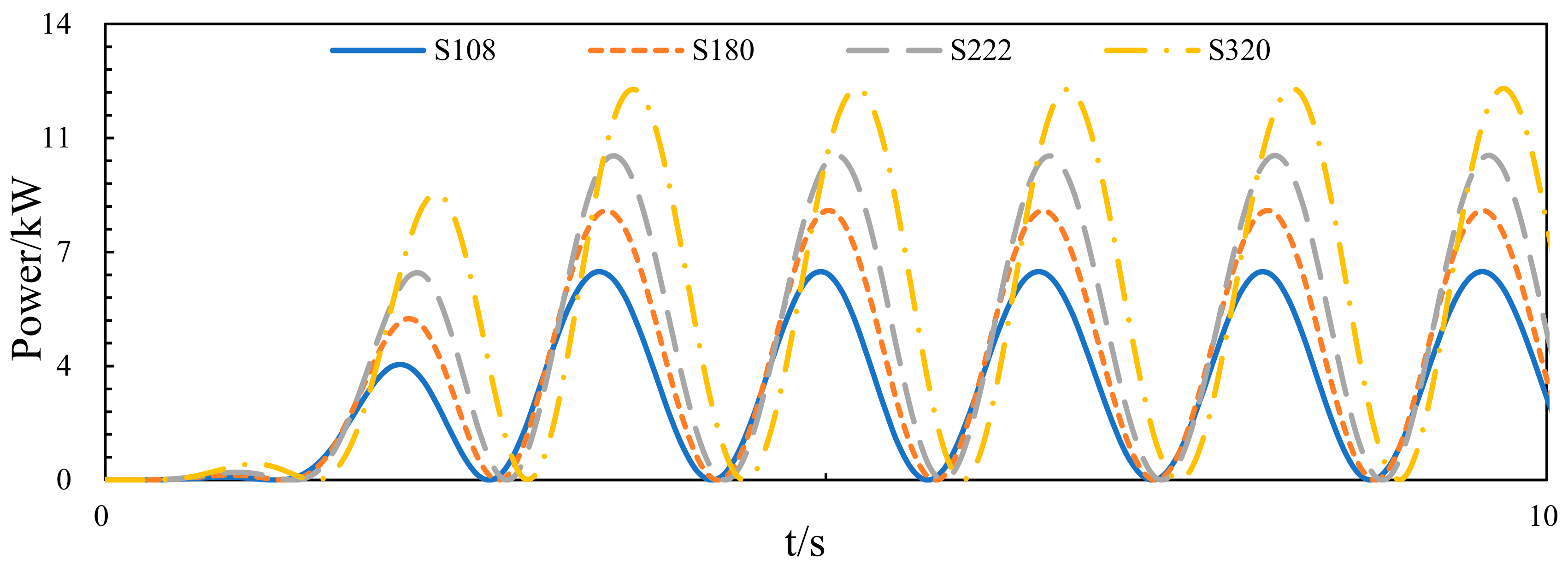
Figure 11 and Figure 12 show the instantaneous power curves of Buoy 1 and Buoy 2, respectively. It can be seen that the maximum value of instantaneous power of Buoy 1 is 9.1 kW when the area of damping layer is 320 m2 and the minimum value occurs when the area is 108 m2, which is about 6.8 kW. For Buoy 2, the maximum value is 12 kW when the area is 320 m2 and the minimum value is 6.3 kW when the area is 108 m2. Figure 13 is the curve of capture width ratio with the area of the damping layer, which shows the capture width ratio of the device generally increases as the area of the damping layer increases. In order to better show its regularity, one set of simulation data was added in the process of drawing the curve, which is S = 268.8 m2 (L*W is 11*24.4). When the area of damping layer is smaller than 222 m2, the capture width ratio of Buoy 1 is better than Buoy 2, and the difference is narrowed as the area increases. However, when the area of the damping layer is further increased, the wave energy capture ratio of Buoy 1 reduced significantly while Buoy 2 increased gradually and finally stabilized.
The above results show that appropriately increasing the area of the damping layer of the central platform is beneficial to increasing the wave energy capture width ratio of the device, and could improve the wave energy collection efficiency.

3.3. Numerical Results at Different Heights of the Damping Layer

3.3.1. Hydrodynamic Performance of the Central Platform

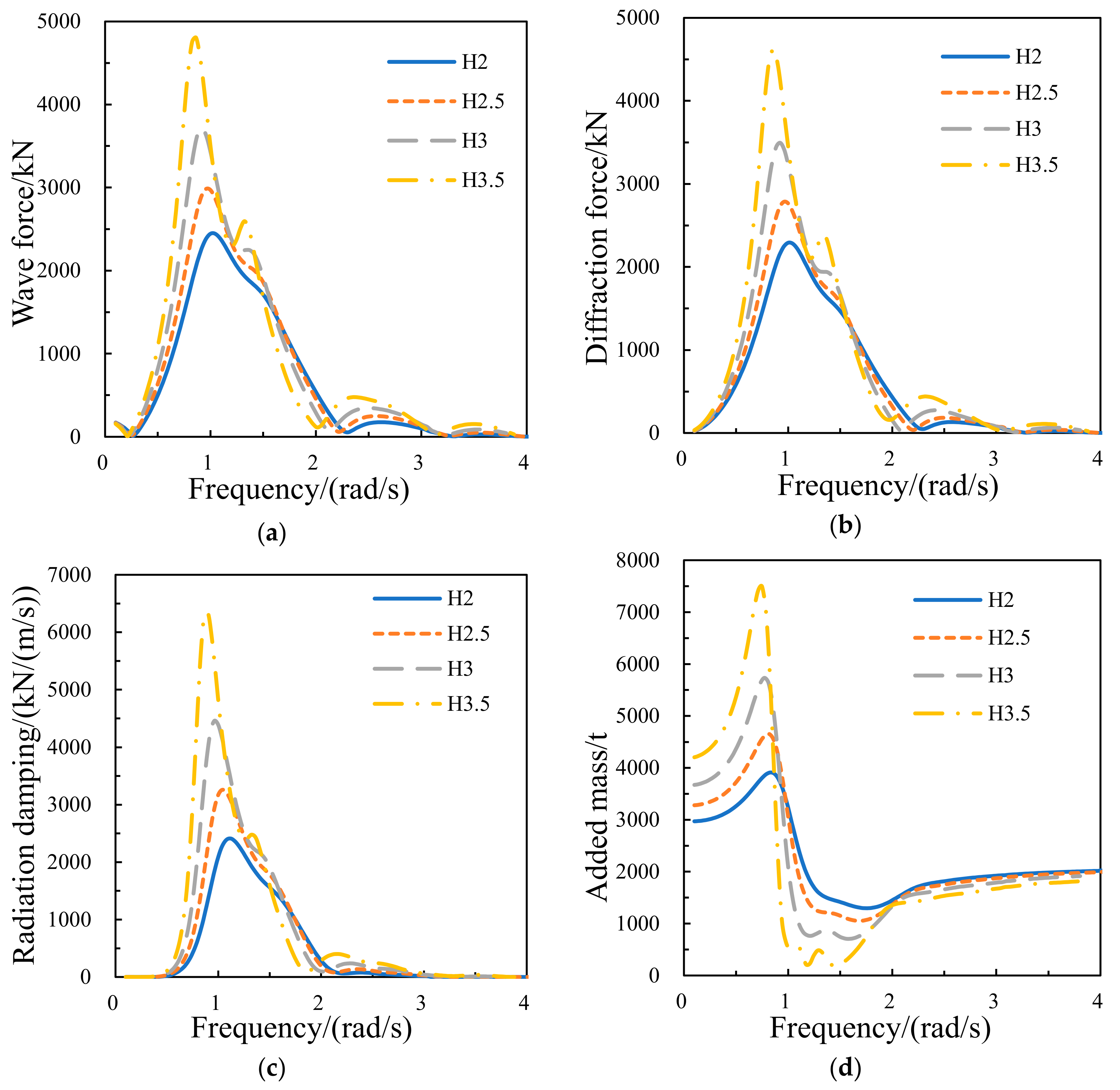
The height of damping layer refers to H, which has already been presented in Figure 2. The influence of different heights on hydrodynamic performance was examined with four different H ranging from 2 to 3.5 m. According to the simulation results above, the WEC has better efficiency when the aspect ratio and area of the damping layer are 0.45 and 320 m2, respectively. Hence, in this simulation, the aspect ratio and area of the damping layer are 0.45 and 320 m2, respectively.
Figure 14 shows the hydrodynamic performance curves of the central platform, it can be seen that wave force, diffraction force, radiation damping, and added mass all increase with the increasing height of the damping layer. For the wave force, the diffraction force, the radiation damping, and added mass, the range of wave frequency corresponding to the peak value of the curve is between 0.82–1.05, 0.86–1.07, 0.86–1.1, and 0.74–0.86 rad/s, respectively, which means the wave frequency at the peak of the curves decrease slightly with the increasing height of the damping layer.
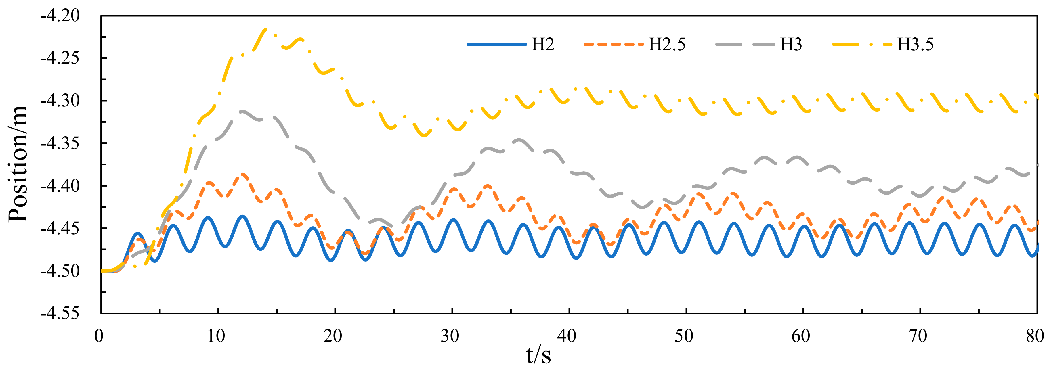
Figure 15 shows the oscillation curves of the central platform, which indicated that when the height of damping layer is 2 m, the central platform has the smallest amplitude of oscillation, and the difference in oscillation amplitude of the central platform is obvious under different heights of damping layer, which means the height of the damping layer has a large effect on the platform oscillation. We considered that when the height of the damping layer increases, the damping layer would be subjected to stronger wave forces owing to increasing the area of contact with the wave, which results in stronger oscillation of the central platform.

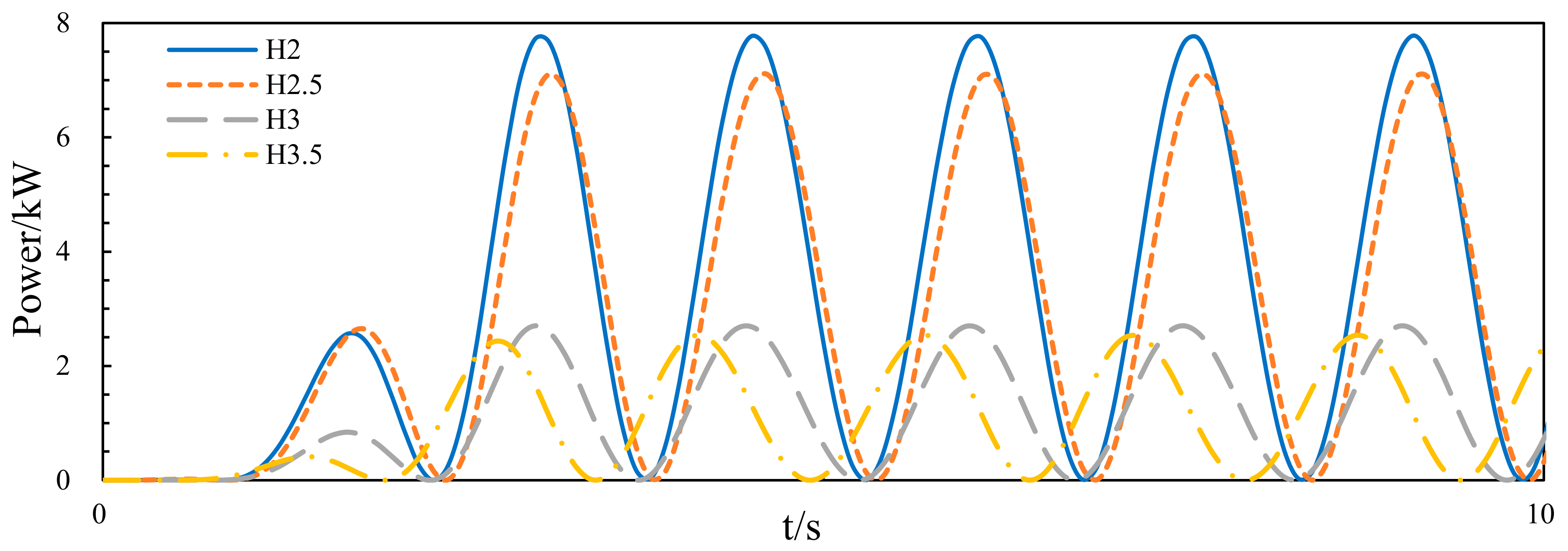
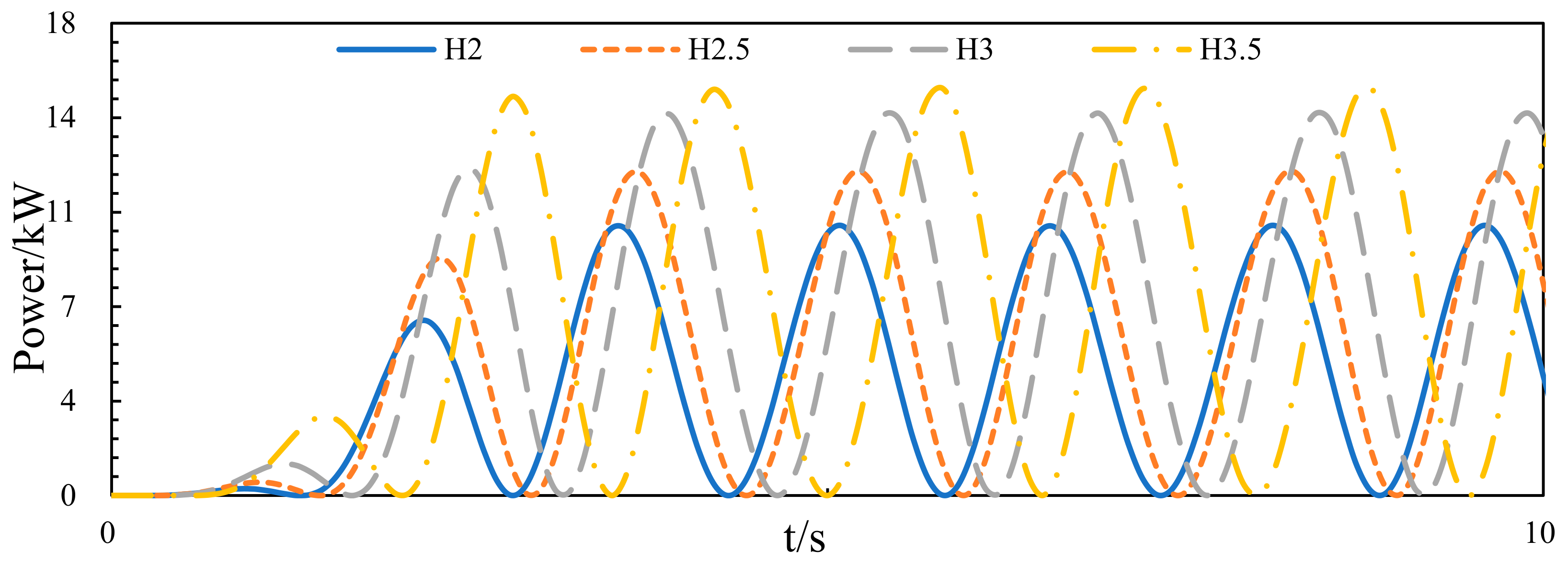
3.3.2. Wave Energy Capture Width Ratio of the Device

Figure 16 and Figure 17 show the instantaneous power curves of Buoy 1 and Buoy 2, respectively. It can be seen that Buoy 1 and Buoy 2 have completely opposite power characteristics, by which the maximum value of instantaneous power of Buoy 1 is 7.7 kW when the height of damping layer is 2 m and the minimum value occurs when the height is 3.5 m, which is about 2.5 kW. For Buoy 2, the maximum value is 15.1 kW when the height is 3.5 m and the minimum value is 10 kW when the height is 2 m. Figure 18 is the curve of capture width ratio with height of damping layer, which shows the capture width ratio of the device is slightly increased as the height of damping layer increases. However, Buoy 1 and Buoy 2 have completely different characteristics, which means the wave energy capture ratio of Buoy 1 decreases as the height of the damping layer increases, while Buoy 2 increases as the height of the damping layer increases.
The above results show that increasing the height of the damping layer of the central platform only has little benefit to increasing the wave energy capture width ratio of the device, but it has a huge impact on the buoys in different positions.

3.4. Numerical Results at Different Drafts of the Damping Layer

3.4.1. Hydrodynamic Performance of the Central Platform

The draft of the central platform indicates the depth of the central platform below the sea surface, which could be represented by h. The influence of different drafts on hydrodynamic performance was examined with four different h ranging from 4.1 to 5.6 m. According to the simulation results above, we already found a better geometric parameter of the damping layer. Hence, the geometric parameter of the damping layer remains unchanged, which means the aspect ratio of the damping layer, the area of the damping layer, and the height of the damping layer are 0.45, 320 m2, and 3.5 m, respectively.
Figure 19 shows the hydrodynamic performance curves of the central platform, it can be seen that wave force, diffraction force, radiation damping, and added mass all decrease with the increasing draft of the central platform. For the wave force and the diffraction force, the range of wave frequency corresponding to the peak value of the curve is between 0.63 and 1 rad/s; for the radiation damping, the range of wave frequency corresponding to the peak value of the curve is between 0.67 and 1.1 rad/s; and for the added mass, the range of wave frequency corresponding to the peak value of the curve is between 0.63 and 0.9 rad/s, which means the wave frequency at the peak of the curves increases as the draft of the central platform increases.
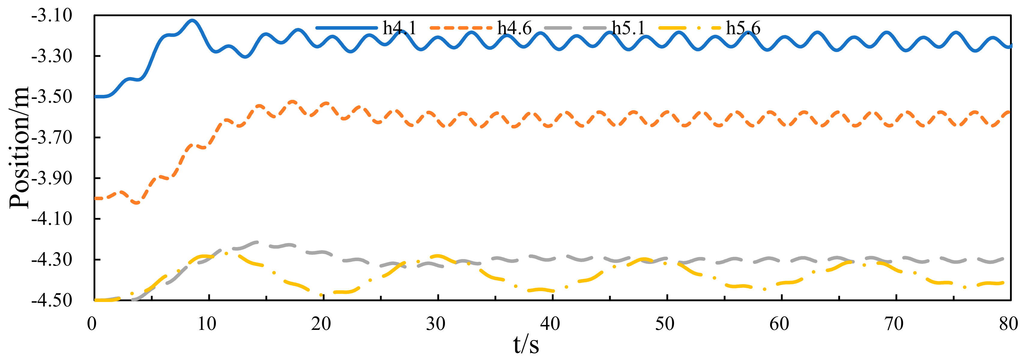
Figure 20 shows the oscillation curves of the central platform, which indicated that when the draft of central platform is 5.1 m, the central platform has the smallest amplitude of oscillation, and the difference in oscillation amplitude of the central platform is great under different drafts of the central platform. This means the draft of the damping layer has an effect on the platform oscillation. We considered that the oscillation amplitude of the platform can be reduced by increasing the platform draft appropriately, then it would indirectly promote the relative oscillation between the buoys and central platform. However, as the draft of the platform increased, the shape of the draft part of the platform would change (a part of the floating layer would be below the waterline), which may lead to changes in the hydrodynamic performance of the platform, and would affect the oscillation of the platform.

3.4.2. Wave Energy Capture Width Ratio of the Device

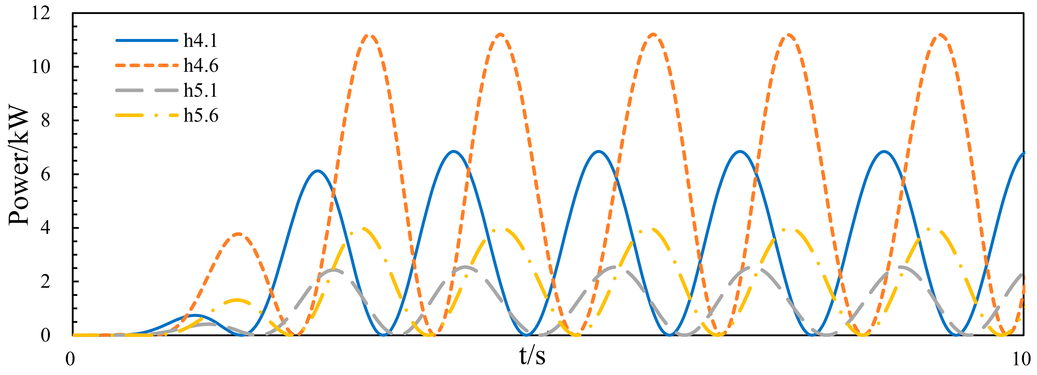
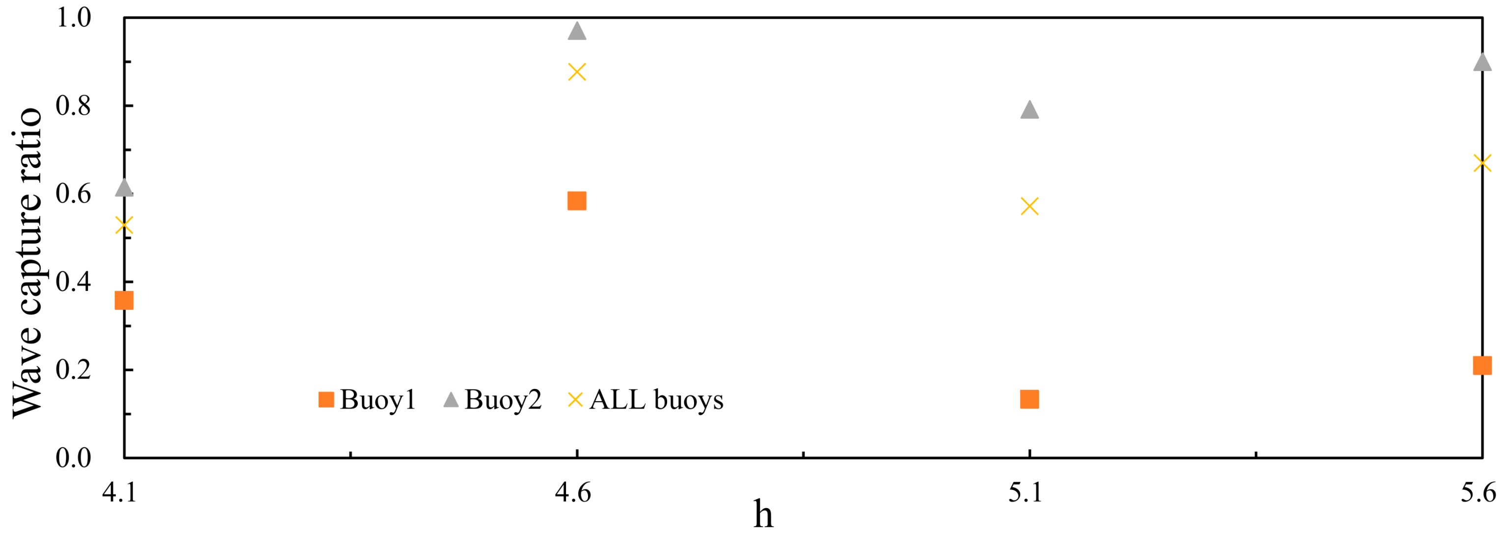
Figure 21 and Figure 22 show the instantaneous power curves of Buoy 1 and Buoy 2, respectively. It can be seen that the maximum value of instantaneous power of Buoy 1 is 11.2 kW when the draft of the central platform is 4.6 m and the minimum value occurs when the height is 5.1 m, which is about 2.5 kW. For Buoy 2, the maximum value is 19.7 kW when the draft of central platform is 4.6 m and the minimum value is 11.8 kW when the draft is 4.1 m. Figure 23 is the curve of capture width ratio with height of damping layer, which shows the capture width ratio of the device is increased when the draft of central platform is between 4.1 and 4.6 m, slightly reduced as the draft further increases, and finally slightly increases. Additionally, the characteristics of Buoy 1 and Buoy 2 are consistent.
The above results show that the relationship between the wave energy capture width ratio and the draft of the central platform is nonlinear. The maximum value of wave energy capture is about 0.87 when the draft of central platform is 4.6 m, which means when the depth of the device reaches 4.6 m, the wave energy collection efficiency of the device is the best.

4. Discussion

The numerical analysis results indicated that the geometry of the central platform does have a great effect on hydrodynamic performance of the WEC. Additionally, the wave energy acquisition efficiency of buoys at different positions is also greatly influenced by the platform geometry. The analysis of the aspect ratio of the damping layer of the platform is to determine whether the dam class (platform has a small aspect ratio) is beneficial to the wave energy absorption of the WEC or the ship class (platform has a large aspect ratio). The results show that when the damping layer has a small aspect ratio, the WEC has better wave energy acquisition efficiency. This may provide an idea for the future design of this type of WEC, which is to design the shape of the central platform as a dam. The effect of the damping layer area on the wave energy acquisition efficiency of the WEC is expected, since the energy collection principle of the WEC is based on the relative motion between the buoys and central platform. The larger platform has a smaller oscillation amplitude, which indirectly improves the relative motion between the buoys and central platform. Additionally, to properly increase the platform’s draft is also to reduce the platform’s oscillation amplitude, which is consistent with increasing the area of the damping layer.
The analysis of the height variation of the damping layer did have some interesting results. When the height of the damping layer changes, the wave energy capture ratio of the WEC remains nearly constant. However, there is a huge difference in the wave energy capture ratio of Buoy 1 and Buoy 2. Unfortunately, we have not found out the specific cause of this phenomenon, it can only be assumed that the change in the height of the damping layer results in the change of distribution of the wave field around the buoys. Additionally, the sea trial test of the full-sized device is planned to be carried out in 2020, which may help to validate the results of the numerical analysis.
Since the author’s learning ability is limited, there is insufficiency in this article’s profundity and breadth, which needs to be improved by the author’s further study in the future. In addition, the purpose of this paper is to prove that the geometry of the central platform has great effect on hydrodynamic performance of the WEC instead of finding the optimal structure of the central platform in the full space of admissible parameters. Hence, the parameters of the central platform presented in the paper have limitations.

5. Conclusions

In summary, the hydrodynamic analysis of a semi-submerged multi-buoy WEC was carried out in the frequency and time domains. The effect of aspect ratio, area, and height of the damping layer and the draft of the central platform on the wave energy capture width ratio of the WEC were explored. The comparison between Buoy 1 and Buoy 2 was made to elucidate the difference in the wave energy capture performance of buoys on the same wave condition but at different positions. Based on the research above, the following conclusions can be drawn:
(1)
There exists a relationship between the hydrodynamic performance of the WEC and the geometry of central platform.
(2)
For a certain wave condition, there exists an optimal geometry of the central platform. At the wave condition mentioned in the paper, when the aspect ratio of the damping layer is 0.45, the area of the damping layer is 320 m2 and the height of the damping layer is 3.5 m, the wave energy capture width ratio of the WEC is better, so that more wave energy can be extracted from the ocean.
(3)
It is found that increasing the draft of the central platform is conducive to improving the wave energy capture width ratio of the WEC, and in this paper, the wave energy capture width ratio of the WEC is the largest when the draft of the central platform is 4.6 m.
(4)
Further related research should be carried out in a physical prototype test and focused on fluid analysis of the central platform, to find out the influence of different shaped platforms on wave distribution.

Author Contributions

Conceptualization, S.Y.; methodology, S.Y.; software, Y.H.; validation, Y.H.; formal analysis, Y.H.; investigation, Y.H.; resources, S.Y., H.H. and H.C.; data curation, Y.H.; writing—original draft preparation, Y.H.; writing—review and editing, S.Y.; visualization, Y.H.; supervision, S.Y.; project administration, S.Y., H.H. and H.C.; funding acquisition, Y.H. All authors have read and agreed to the published version of the manuscript.

Funding

This research was funded by the National Natural Science Foundation of China (Grant No. 51779104), the Natural Science Foundation of Fujian Province, China (Grant No. 2016J01247), and the Foreign Cooperation Project of Department of Science and Technology of Fujian Provincial (Grant No. JA13170).

Acknowledgments

The authors would like to thank Shaohui Yang from Jimei University for his support on experiments and paper modification.

Conflicts of Interest

The authors declare no conflict of interest.

References

  1. Wang, L.G.; Isberga, J. Review of control strategies for wave energy conversion systems and their validation, the wave-to-wire approach. Renew. Sustain. Energy Rev. 2018, 81, 366–379. [Google Scholar] [CrossRef]
  2. Khana, N.; Kalaira, A.; Haiderc, N.A. Review of ocean tidal, wave and thermal energy technologies. Renew. Sustain. Energy Rev. 2017, 72, 590–604. [Google Scholar] [CrossRef]
  3. Soukissian, T.H. Marine renewable energy in the Mediterranean Sea: Status and perspectives. Energies 2017, 10, 1512. [Google Scholar] [CrossRef] [Green Version]
  4. Yang, S.H.; Wang, Y.Q.; He, H.Z.; Zhang, J.; Chen, H. Dynamic properties and energy conversion efficiency of a floating multi-body wave energy converter. China Ocean Eng. 2017, 3, 108–118. [Google Scholar] [CrossRef]
  5. Kramer, M.; Marquis, H.; Frigaard, P. Performance evaluation of the Wavestar prototype. In Proceedings of the 9th European Wave and Tidal Conference (EWTEC), Southampton, UK, 5–9 September 2011. [Google Scholar]
  6. Hansen, R.H.; Kramer, M.; Vida, E. Discrete displacement hydraulic power take-off system for the Wavestar WEC. Energies 2013, 6, 4001–4044. [Google Scholar] [CrossRef]
  7. Ambühl, S.; Kramer, M.; Sørensen, J.D. Reliability-based structural optimization of WECs. Energies 2014, 7, 8178–8200. [Google Scholar] [CrossRef] [Green Version]
  8. Yang, S.H.; He, H.Z.; Zhang, J.; Chen, H. Design and experimental study of raft array type wave energy generating system. J. Mech. Eng. 2016, 11, 57–62. [Google Scholar] [CrossRef]
  9. Zhang, M.Y.; Yang, S.H.; He, H.Z.; Zhang, J.; Li., H. Modeling and simulation analysis of array type wavy energy generator. Ocean Eng. 2017, 2, 83–88. [Google Scholar]
  10. Sheng, S.Y.; Zhang, Y.Q.; Wang, K.L.; Wang, Z.P.; Lin, H.J.; Ye, Y. Research on the wave energy generating device of Eagle1. Ship Eng. 2015, 9, 104–108. [Google Scholar]
  11. Sheng, S.Y.; Zhang, Y.Q.; Wang, K.L.; Lin , H.J.; Wang, W.S.; Chen, A. Overview of the overall design of the Eagle device Wanshan. Ship Eng. 2015, 37, 10–14. [Google Scholar]
  12. Wang, W.S.; Sheng, S.Y.; Ye, Y.; Zhang, Y. Frequency domain motion analysis and optimization design of eagle1 wave energy device. Ocean Technol. 2018, 2, 101–106. [Google Scholar]
  13. Sheng, S.Y.; Zhang, Y.Q.; Wang, K.L.; Ye, Y.; You, Y. Research on generation system of eagle wave energy generator. Renew. Energy Resour. 2015, 9, 1422–1426. [Google Scholar]
  14. Zhang, Y.Q.; Sheng, S.W.; You, Y.G.; Huang, Z.X.; Wang, W.S. Study of hydrodynamic characteristics of a sharp eagle WEC. China Ocean Eng. 2017, 3, 364–369. [Google Scholar] [CrossRef]
  15. Sheng, S.Y.; Wang, K.L.; Lin, H.J.; Zhang, Y.; You, Y.; Wang, Z.; Chen, A.; Jiang, J.; Wang, W.; Ye, Y. Model research and open sea tests of 100 kW wave energy convertor sharp eagle Wanshan. Renew. Energy 2017, 113, 587–595. [Google Scholar] [CrossRef]
  16. Hu, Y.; Yang, S.H.; He, H.Z.; Chen, H.; Zheng, S.; Zhang, D. Hydrodynamic performance analysis of semi-submersible multi-body wave power plant. J. Ocean Eng. 2019, 38, 1–13. [Google Scholar]
  17. Zheng, S.M.; Zhang, Y.H.; Zhang, Y.L.; Sheng, W.A. Numerical study on the dynamics of a two-raft wave energy conversion device. J. Fluids Struct. 2015, 58, 271–290. [Google Scholar] [CrossRef]
  18. Babarit, A.; Hals, J.; Muliawan, M.J.; Kurniawan, A.; Moan, T.; Krokstad, J. Numerical benchmarking study of a selection of wave energy converteors. Renew. Energy 2012, 41, 44–63. [Google Scholar] [CrossRef]
  19. Babarit. A database of capture width ratio of WECs. Renew. Energy 2015, 80, 610–628. [Google Scholar] [CrossRef]
  20. Jefferys, E.R. Device characterization. In Power from Sea Waves; Count, B., Ed.; Academic Press: London, UK, 1980; pp. 413–438. [Google Scholar]
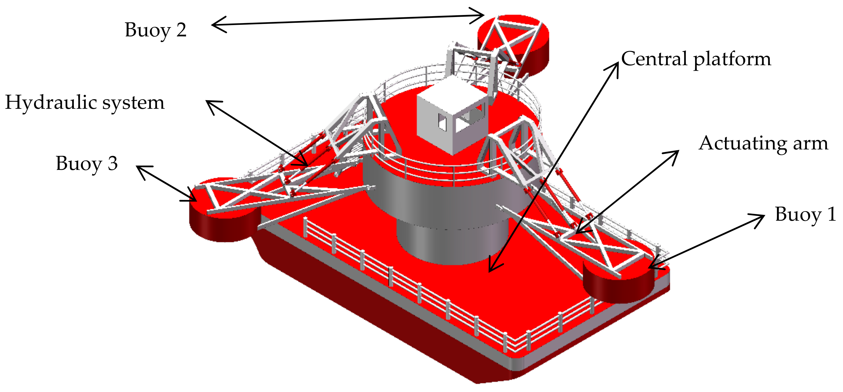
Figure 1. Semi-submerged multi-buoy wave energy converter (WEC).
Jmse 08 00012 g001
Figure 2. The dimensions of the central platform.
Jmse 08 00012 g002
Figure 3. Grid model of semi-submerged multi-buoy WEC.
Jmse 08 00012 g003
Figure 4. Four hydrodynamic parameter curves: (a) wave force, (b) diffraction force, (c) radiation damping, (d) added mass.
Jmse 08 00012 g004aJmse 08 00012 g004b
Figure 5. Oscillation curve of the central platform.
Jmse 08 00012 g005
Figure 6. The instantaneous power curves of Buoy 1.
Jmse 08 00012 g006
Figure 7. The instantaneous power curves of Buoy 2.
Jmse 08 00012 g007
Figure 8. Curve of capture width ratio with aspect ratio.
Jmse 08 00012 g008
Figure 9. Four hydrodynamic parameter curves. (a) Wave force, (b) diffraction force, (c) radiation damping, (d) added mass.
Jmse 08 00012 g009
Figure 10. Oscillation curve of the central platform.
Jmse 08 00012 g010
Figure 11. The instantaneous power curves of Buoy 1.
Jmse 08 00012 g011
Figure 12. The instantaneous power curves of Buoy 2.
Jmse 08 00012 g012
Figure 13. Curve of capture width ratio with area.
Jmse 08 00012 g013
Figure 14. Four hydrodynamic parameter curves. (a) Wave force, (b) diffraction force, (c) radiation damping, (d) added mass.
Jmse 08 00012 g014
Figure 15. Oscillation curve of the central platform.
Jmse 08 00012 g015
Figure 16. The instantaneous power curves of Buoy 1.
Jmse 08 00012 g016
Figure 17. The instantaneous power curves of Buoy 2.
Jmse 08 00012 g017
Figure 18. Curve of capture width ratio with height.
Jmse 08 00012 g018
Figure 19. Four hydrodynamic parameter curves. (a) Wave force, (b) diffraction force, (c) radiation damping, (d) added mass.
Jmse 08 00012 g019
Figure 20. Oscillation curve of the central platform.
Jmse 08 00012 g020
Figure 21. The instantaneous power curves of Buoy 1.
Jmse 08 00012 g021
Figure 22. The instantaneous power curves of Buoy 2.
Jmse 08 00012 g022
Figure 23. Curve of capture width ratio with draft.
Jmse 08 00012 g023
Table 1. Initial parameters of the damping layer and buoys.
DesignationParameters
Molded length18 m
Molded width10 m
Molded height2.5 m
Diameter of buoy3.2 m
Height of buoy2 m
Draft depth of the device5.1 m
Table 2. The values of L and W in each computation.
BL/W (m)
113.4/13.4
1.2515/12
1.818/10
2.2220/9
2.6922/8.18
Table 3. The values of L and W in each computation.
S (m2)LW (m)
1087 × 5.56
1809 × 20
22210 × 22.2
32012 × 26.67