1. Introduction
Beaches play an essential role in the life of an ecosystem. They participate in water purification, nutrient renewal, coastal defense, recreational activities, etc. Previous studies have stated that the use of beach does not integrate well with the importance of maintaining sustainable resources. These studies considered beach use as a cause of environmental degradation and imbalance in the sedimentary process [
1,
2,
3]. Fast-growing tourism, coastal development, and global climate change can worsen the degradation impact [
4,
5,
6].
To better understand their socioeconomic and engineering impacts, these erosion problems need to be assessed via the physical processes of the coastal zone [
7]. Some indicators, such as shoreline positions, beach morphology, coral reef condition, hydro-oceanography condition, and coastal structures, can be used to assess erosion problems, and the results of this assessment should be considered for the development of coastal management.
Some cases of beach erosion are due to imbalances in sediment transport, which are caused by the longshore sediment transport. Previous studies have analyzed the impact of longshore sediment transport on the conditions of coastal areas [
8,
9,
10,
11,
12]. Bergillos et al. [
10], analyzed the relationship between the morphology of the conserved beach and longshore sediment transport. These conditions can be affected by some factors, such as the change in bathymetry condition and the predominant wave condition [
8]. The changes in sediment volume can also be analyzed by using the longshore sediment transport gradient [
8]. Furthermore, Andrade et al. [
1], concluded that via the change in beach width and shoreline position, the gradients of longshore drift play an essential role in erosion processes.
The main aim of this study is to assess the erosion problems at Nusa Dua Beach of Bali Indonesia, based on the data from the beach monitoring survey. The assessment of the longshore drift process and equilibrium shoreline are the primary tools used for checking the erosion problems. The results of this research will serve as guidance for planning and developing the next strategic approach in coastal management.
2. Characterization of Study Area
Bali is one of the most popular tourist sites in Indonesia. In 2017, tourism constituted almost 23% of the gross regional domestic product of Bali [
13]. With a coastline stretching 633 km, beaches remain the most popular tourist destination in Bali. The southern part of Bali has a flourishing tourism industry and some of its beaches, such as Nusa Dua, Sanur, Kuta, and Tanah Lot, are particularly popular tourist destinations. Additionally, the beaches are of significant value to the Balinese Hindu population.
However, according to the 2015 survey data obtained by the Indonesian Ministry of Public Works and Housing, erosion in Bali has affected 215 km of the coastline. Coastal erosion has recently become a global environmental problem. Most coastlines suffer from erosion owing to the sediment deficit caused by human disturbances such as damming, land reclamation, urbanization, and coastal area development [
14,
15,
16,
17,
18,
19]. Over 70% of the world’s beaches suffer from erosion [
20]. One of the goals of integrated coastal zone management's (ICZM) is to improve beach quality. The European Commission [
21] has noted coastal erosion as an issue that must be addressed in ICZM strategies. Coastal erosion may generate several negative impacts on social-economical aspect such as the potential loss of life, damage of property and infrastructure, loss of tourism revenue, and degradation of the ecosystem.
The study area for this work is located on Nusa Dua Beach, from groin G12 to the north part of groin GA2, with a total shoreline of approximately 2.8 km (
Figure 1). Located in the southern part of Bali Island, in front of Benoa Strait, Nusa Dua has been one of the most famous Bali beach resorts for several years. Up to the eastern part of the north coast of Tanjung Benoa, the beach is made of carbonaceous sand and foraminiferan components. The beach slope is slightly steep and steadily levels as it nears the sea. Based on the data obtained after a beach nourishment project, the grain size (D
50) at Nusa Dua Beach is 0.606 mm.
The beach erosion problem at Nusa Dua was caused by the interruption of the northward littoral drift by a natural tombolo behind the Nusa Kecil and Nusa Besar islands that occurred several decades [
22]. The other reason for the erosion problem is a reduction in the reef flat owing to coral mining. The lower reef flat allows waves with high energy to be propagated to the beach. The decreased supply of sand creates an imbalance in the sediment budget. Furthermore, the general stress from the disturbance on the beach area induces localized erosion.
From 2001 to 2003, the Indonesian Ministry of Public Works in collaboration with Japan International Cooperation Agency completed the Bali Beach Conservation Project Package II at Nusa Dua by implementing civil works such as beach nourishment, and constructing coastal structures. The coastal conservation and protection efforts essentially propped the tourism at Nusa Dua Beach. The project focused on maintaining the beach from a functional perspective and developing a plan for its utilization as a tourist area and its landscaping while protecting and conserving the beach environment. Furthermore, the project facilitated the construction of several groins to stabilize the shoreline and protect it from longshore drift. Hence, the coastline has the same phase potential line. These artificial headlands divided Nusa Dua Beach into several sublittoral cells. To optimize its effectiveness, the beach nourishment project needs to be adjusted with the coastline morphology, sediment grain size, and input volume [
11].
The wave direction is predominantly south and south east. This oblique wave is reflected by the shoreline generating a northerly longshore current. Its motion is one of the external forces responsible for either erosion or sedimentation in the area. The tidal characteristic in the Nusa Dua area is mixed semidiurnal. Based on the tidal elevation design for the beach conservation project, the highest water level obtained was 2.6 m higher than the lowest water level (LWL). Hence, the mean sea level was 1.3 m above the LWL.
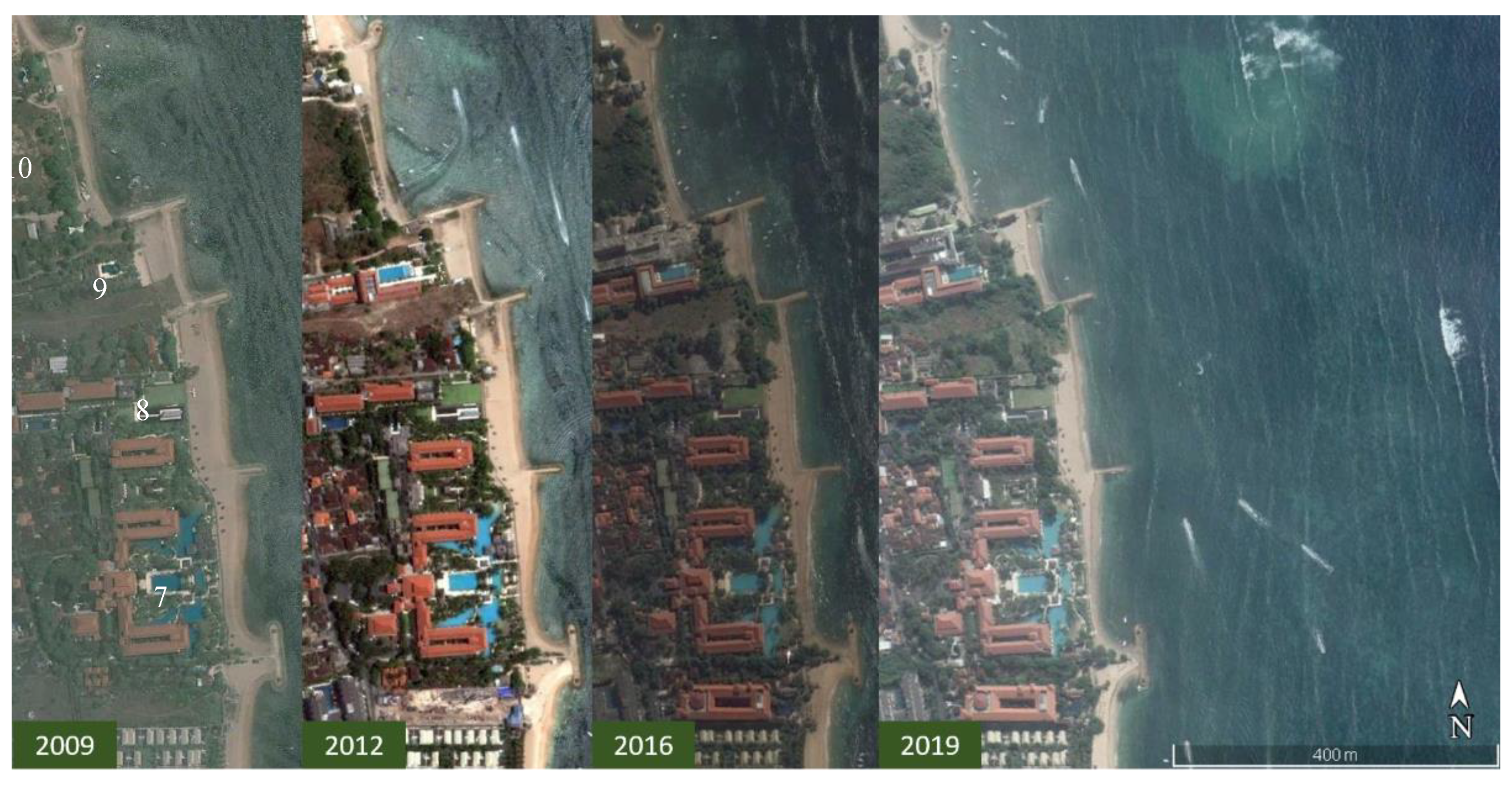
From 2003 to 2016, a beach profile survey was conducted in some sections of Nusa Dua Beach by the Indonesian Ministry of Public Works and Housing. This activity provided useful information necessary for understanding the beach erosion phenomena. After the beach conservation project was completed, the change in shoreline was evident in a time series of satellite images from Google Earth (
Figure 2).
Owing to this condition, the coastal system was divided into 17 sublittoral cells in this study (
Table 1 and
Figure 3). Because the dominant wave comes from the south, the numbering of the sublittoral cells started from the south and then moved northward.
Most of the groins at the Nusa Dua Beach were constructed during the beach conservation project. At that time, one system served as the sublittoral cell between GA8 and GA3; this was also true, for the segment between GA3 and GA2. However, after several years, private and government projects constructed four groins between these two systems: GN 5 and GN 6 in 2009, GTB in 2010, and GN4 in 2011. Therefore, the sublittoral cell between GA8 and GA3 is divided into three control volumes, as is the segment between GA3 and GA2.
3. Theoretical Background
3.1. Sediment Budgets
A sediment budget analysis is a fundamental element of the framework used for understanding erosion and accretion processes in a coastal zone. This analysis play an essential role in evaluating the impacts of engineering activities, such as providing an understanding of sediment transport magnitudes and pathways in the selected coastal region and within a specified time [
23]. Sediment budgets represent an analysis of sediment balance (gains and losses) in a determined control volume (or sublittoral cell) or an adjacent sublittoral cell system, over a specified time [
24].
The formulation of a sediment budget is derived from the mass conservation equation. In a coastal cell, the difference between sediment budgets over a specified period time must equal the sediment volume change, which occurs in that region. To calculate the sediment budget, the sublittoral cell should be defined as the system’s boundary. The cell is usually defined by geologic controls, coastal structures, available data resolutions, and isolating known quantities or a quantity of interest. The record of sediment volume data in a sublittoral cell is used to formulate a sediment budget.
Rosati [
24] introduced the general equation for analyzing sediment budgets (Equation (1)).
All of the terms in Equation (1) are represented by a volumetric rate. ΔV is the net accumulated change in sediment volume, Qsource and Qsink are the source and sink for the specified system, respectively, P and R are the volumes of sediment placed in or removed from the control volume, respectively, and the residual serves as means for balancing the cell. The residual is zero for a balanced cell.
3.2. Equilibrium Shoreline
The predominant wave direction and coastal structures have a potential impact on the coastline [
25]. The shoreline responds to such processes until an equilibrium is established, which is the balance between internal and external forces. An equilibrium shoreline represents a condition in which the shoreline has reached a stable condition and has the same phase potential line. The equilibrium shoreline analysis is essential to evaluate erosion and accretion processes along the coastline.
Between two headlands, the coastline makes a crenulate-shaped bay [
26] as equilibrium is established. To simulate the plan form of bayed beaches, three concepts including the logarithmic spiral [
27], parabolic shape (
Figure 4) [
26], and hyperbolic tangent [
28] have been developed. Among these three empirical equations, the implications of only the predominant wave direction alone and its diffraction location (control point) have been considered in the parabolic bay shape equation (PBSE) [
26,
29].
The shape of the PBSE (Equations (2) and (3)) [
26] is dependent on two parameters, R
o and β. As the control line, R
o is obtained by determining the "focus point," which is the center of the distance between the diffraction point and the control point, the point that protrudes into the sea, which is still in the same littoral cell. The variable β is the obliquity of the wave, which is the angle created between the control line and the wave crest.
where C
0, C
1, and C
2 are the determined coefficients related to β; R is the radius along the curve at an angle θ, to a specific point; R
o is the radius at an angle β from the wave crest to the control point; θ is an angle from the wave crest to a specific point; and β is the angle determining the parabolic shape.
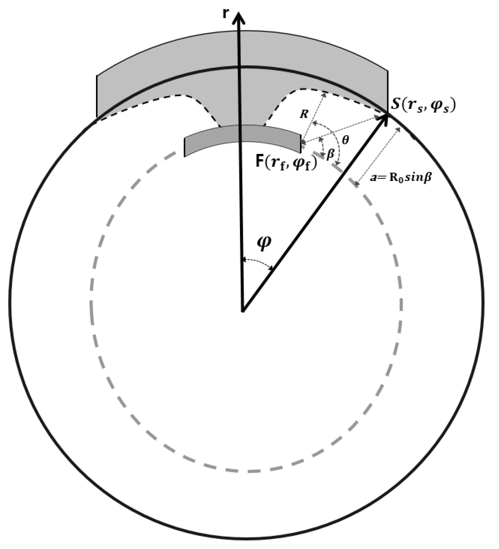
To fit the equilibrium shoreline for a pocket-shaped beach such that the PBSE can be applied to the shoreline curve, this concept must be transformed into polar coordinates [
30]. Then, the coordinates for the center of a circle, with a radius of r
s that fits the shoreline are set, using the polar coordinate system (r, φ). In this coordinate system, the predominant wave direction can be estimated by the angle from the circle origin to the center of beach position. The PBSE is illustrated in
Figure 5 and expressed by the Equations (4) and (5).
where r
f is the distance from the center of the fitting circle to the focus point. Using MeEPASoL as the graphical user interface (GUI) program, these concepts and equations were used in this study to implement the equilibrium shoreline analysis.
4. Materials and Methods
4.1. Erosion Assessment
4.1.1. Beach Profile Area
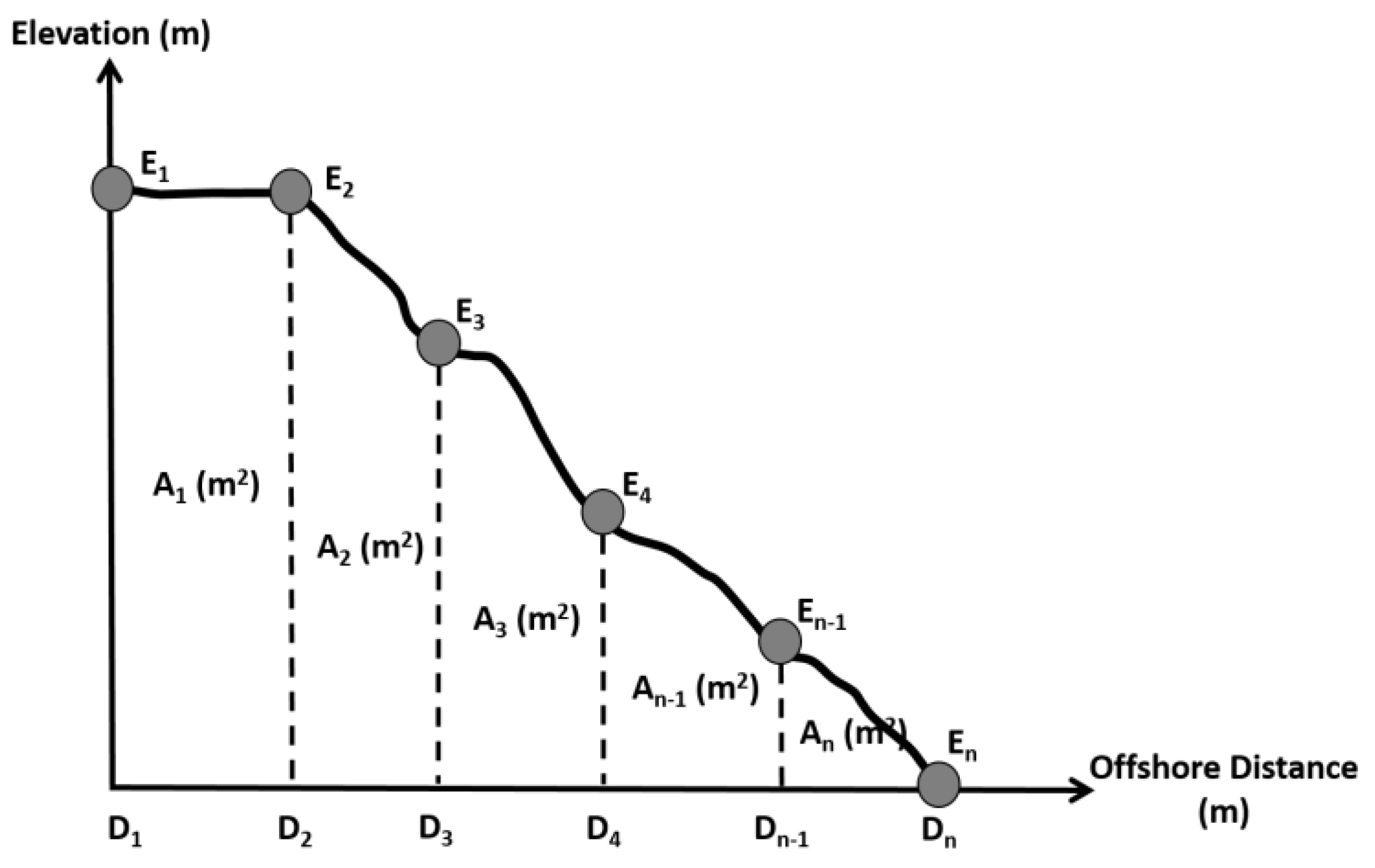
As a response to erosion and accretion, the beach profile changes with time. Temporal and spatial analytical techniques were employed to assess the variations in the profile data along the coastline. These data were used to identify the natural defense of a particular beach profile and determine the changes along the adjacent shoreline (erosion and accretion). A survey was performed using methods such as triangulation, traversing, and the use of a global positioning system (GPS) [
31].
The surveys of the periodic beach profile provided data for the selected area. The arbitrary vertical datum, which is considered as the boundary between the beach and the coral reef, can be chosen for each profile. Then, the sediment area above the baseline, from the baseline to the seaward limit, can be obtained [
32]. The beach monitoring dataset was obtained from the field survey. The survey was conducted by the Indonesian Ministry of Public Works and Housing from December 2003 to January 2016. The area of the beach profile in this study was calculated using the trapezoidal method.
Figure 6 illustrates the calculation of the beach profile area.
Equation (6) expresses the total area of the beach profile for a specific time.
where
,
, and
are the beach profile area for specific cross-section (
l) at a particular time (
t), elevation position data for the
i-point at
t-time for each cross-section, and offshore distance data for the
i-point at
t-time for each cross-section, respectively.
4.1.2. Sublittoral Cell Volume and Rate
The sediment volume in each monitoring period can be calculated after determining the area for all of the cross-sections in the selected sublittoral cell. The sediment volume above the datum can be calculated by integrating the areas from the adjacent beach profile data obtained from the same survey along the coastline. The estimated volume for a certain monitoring period can be used to check the time when erosion and accretion occurred, and the amount of erosion and accretion. Equation (7) expresses the calculation for beach volume.
where
,
, and
are the volume for a specified time in each sublittoral cell, beach profile area for a specific cross-section (
l) at a particular time (
t), and longshore position of the cross-section (
l), respectively. Furthermore, the rate of beach volume change versus time (ΔV/Δt) was determined using linear regression from the calculated volume dataset.
4.2. Predominant Waves Direction and Prediction of Equilibrium Shoreline
The estimation used to predict the equilibrium shoreline for each sublittoral cell was done using MeEPASoL software and the satellite images from Google Earth. MeEPASoL (a GUI program) is an application that simulates the equilibrium shoreline based on the result obtained from the empirical PBSEs (Equations (2) and (3)). This application also estimates the predominant angle of the incident waves as the shoreline orientation. For reliable performance, these equations were applied in the GUI tool to the polar coordinates of existing concave shape shorelines. The prediction of shoreline changes can be estimated by processing the satellite image using the PBSE (
Figure 7).
4.3. Sediment Budgets and Longshore Drift
To quantify the sediment loss or gain in each sublittoral cell, it is necessary to estimate a sediment budget. This analysis is also used to check the correlation of sediment transport from each sublittoral cell to the adjacent area. Furthermore, Equation (1), which was derived from mass conservation principles, can be transformed into Equation (8).
where ΔV/Δt, Q
in, and Q
out are the rate of volume change during the monitoring period, amount of sediment transported into the control volume, and amount of sediment transported out of the control volume, respectively.
The difference in the amount of sediment transport (ΔQ) discussed above is caused by cross-shore sediment transport (Q
c), which is calculated using the beach profile change. However, we assume that the cross-shore sediment transport is transformed to the longshore sediment transport (Q
l). Therefore, this study assumes that Q
in in a specified sublittoral cell comes from the southern sublittoral cell, then Q
out moves to the northern sublittoral cell, as represented by Equation (9).
where Q
n−1 represents the Q
in from the previous sublittoral cell, and Q
n represents the Q
out from this sublittoral cell.
Walton Jr. and Dean [
33] have represented the longshore drift rate as Equation (10).
where
, α
s, and α
b are the longshore drift potential indicating the wave climate of the coast, shoreline orientation owing to the predominant wave direction, and azimuth of the angle of the waves breaking on the shoreline, respectively.
Figure 8 illustrates the shoreline orientation due to the incident main wave angle and the azimuth angle owing to the breaking waves on the shoreline in the sublittoral cell of interest.
Therefore, the gradient of longshore drift (ΔQ) is represented by the difference between the sediment transports in the sublittoral cell of interest and the adjacent area. This amount is influenced by the shoreline orientation (αs) and the azimuth of the breaking wave angle (αb).
Afterward, the gradient of longshore drift (ΔQ), which is the rate of volume change in the sublittoral cell, can be approximated. The shoreline orientation (α
s) for every sublittoral cell was calculated using the MeEPASoL program. However, the azimuth of the breaking wave angle to the shoreline (α
b) is unknown. However, the variation of α
b is small (smaller than the difference in shoreline orientation), as can be seen via the following process. The coral reef zone, which is located in front of the coastline, makes the area similar to shallow water zone. Therefore, the dominant waves from the deep water, which have the same directional angle, are reflected and break. Although the direction of the breaking wave is changed, the change in direction is small. Therefore, Equation (10) can be simplified into Equation (11).
where
is defined as
providing the positive ΔQ toward to the north. This study used the central difference method owing to the effect from the other sublittoral cell to calculate the gradient of the longshore drift (ΔQ) and the gradient of sin (2
s). Finally, the result for the longshore drift potential (
) and correlation value represents the characteristics of the longshore drift process and the relation between the longshore drift and the shoreline orientation.
5. Results
5.1. Erosion Rate and Predominant Wave Direction in the Sublittoral Cell
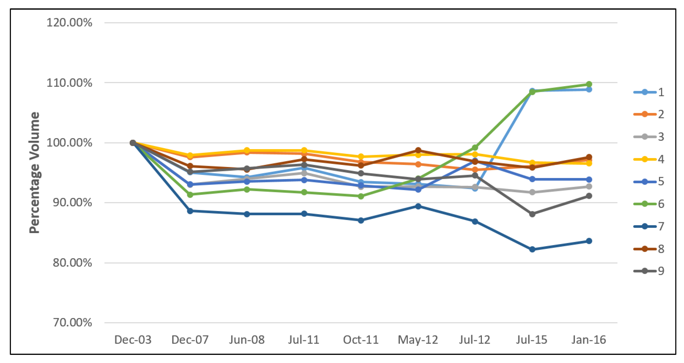
As evident from field survey data obtained from December 2003 to January 2016, the change in sediment budget occurred in every sublittoral cell at Nusa Dua Beach. The shoreline also obtained the equilibrium condition as the response of predominant wave direction and the groin system.
Figure 9 shows the percentage of sand volume change at sublittoral cell 1 until 9, and
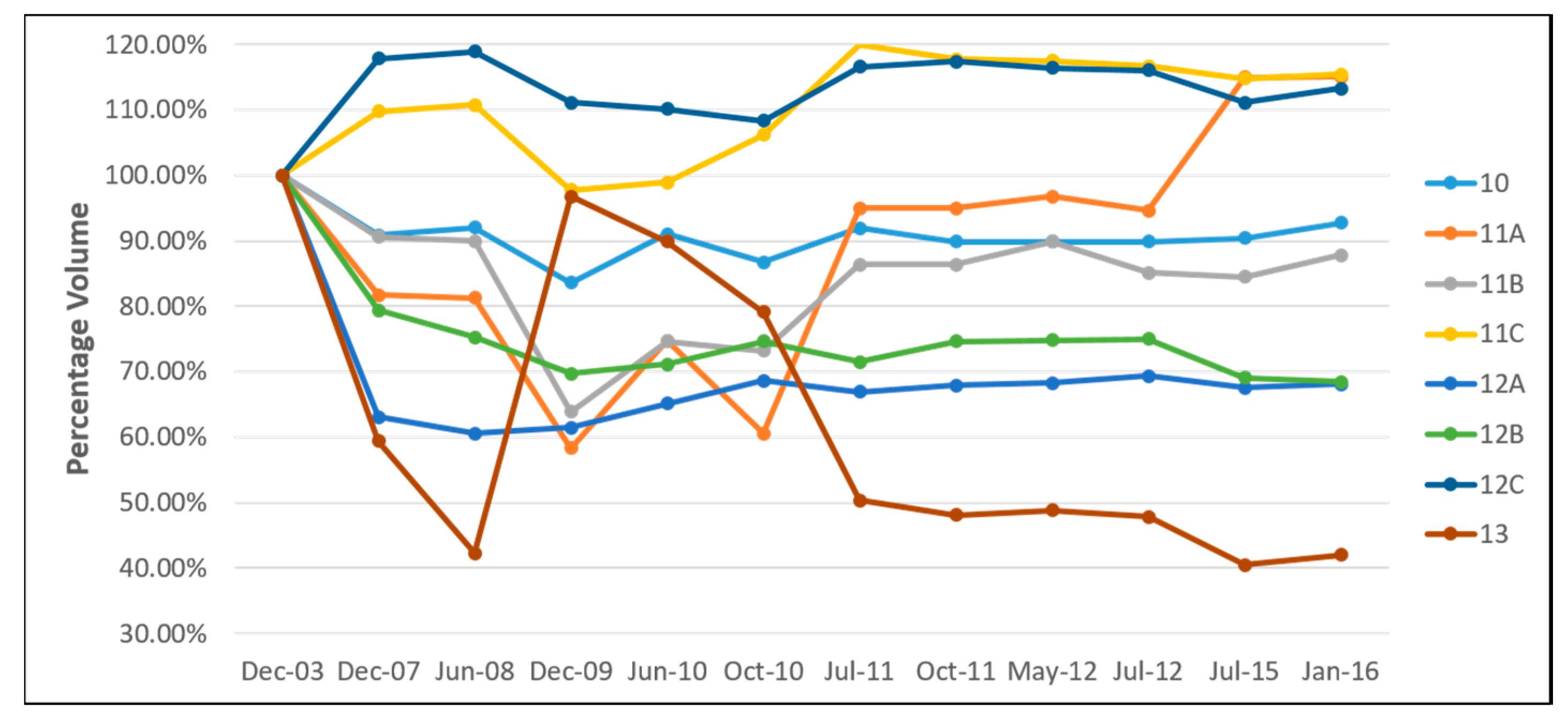
Figure 10 shows the percentage at sublittoral cell 10 until 13.
Therefore, the rate of beach volume change can be obtained from the trend line of every sublittoral cell for further analysis. Some considerations were taken to determine the natural rate of sediment volume in every sublittoral cell. Additional beach nourishment from private entities was neglected in this study.
Table 2 shows the rate of beach volume change in every sublittoral cell and its consideration.
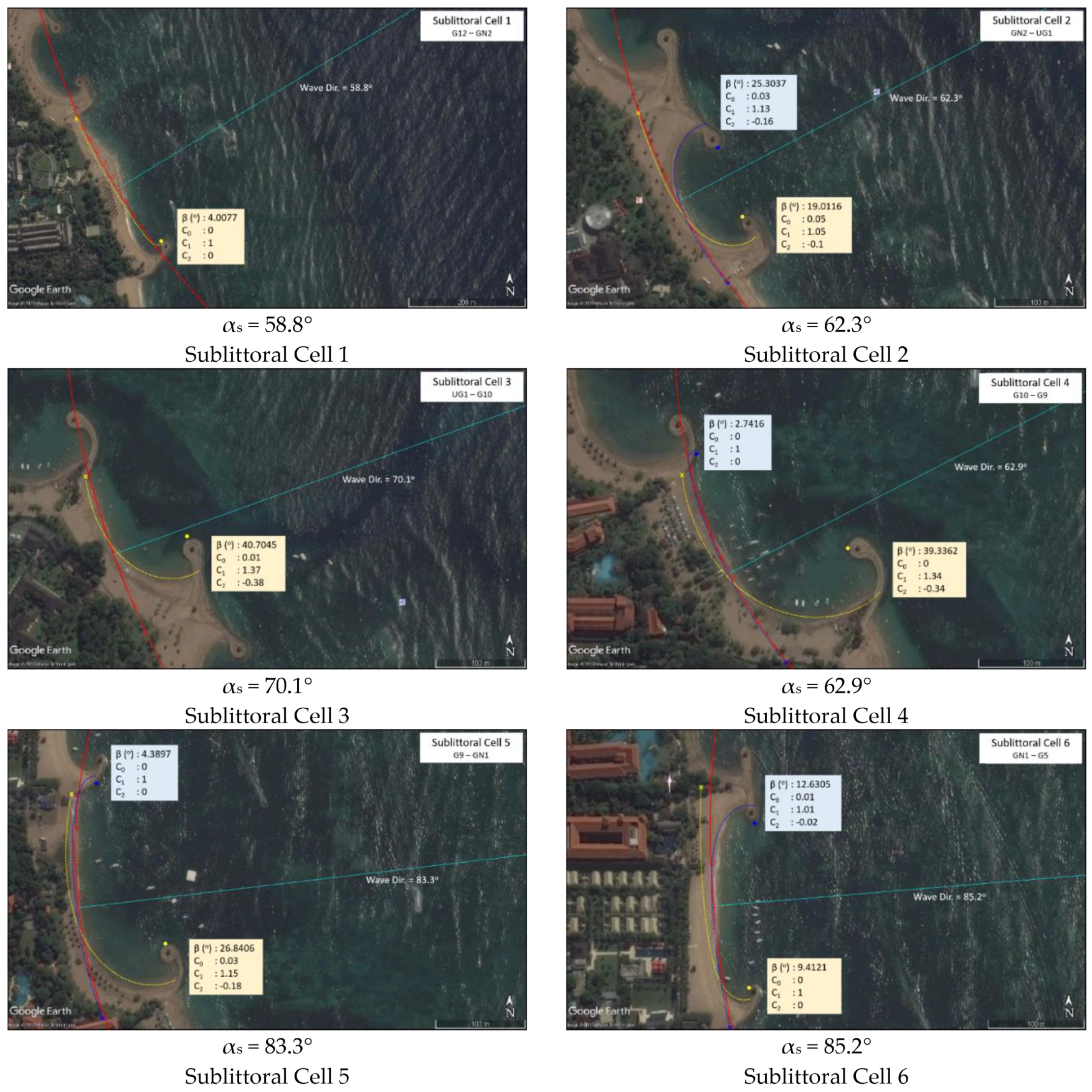
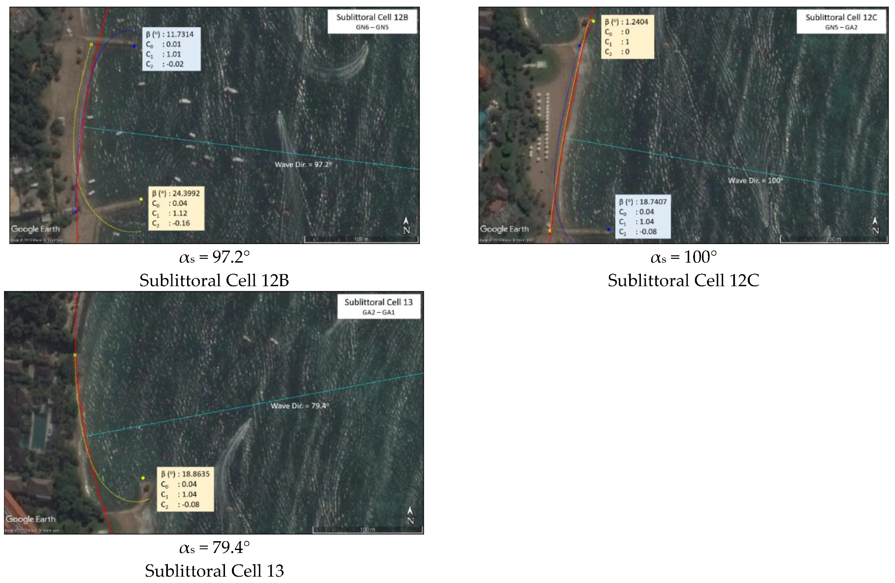
Furthermore, the predominant wave direction as the shoreline orientation in every sublittoral cell was determined using the MeEPASoL software. This simulation (see
Appendix A) also checked the equilibrium shoreline owing to the interaction between the predominant wave and headlands in every sublittoral cell (the predicted equilibrium shoreline is showed in yellow and blue line).
From the simulation results, the shoreline takes the parabolic shape as the equilibrium condition. The shoreline movement and equilibrium condition represent the phase potential line in every sublittoral cell. The shoreline moves from the high phase potential line to the low phase potential line. Then, the predominant wave direction can represent the shoreline orientation in every sublittoral cell. The simulation of equilibrium shoreline using MeEPASoL returns a satisfactory result for Nusa Dua Beach. Furthermore, the results show that erosion problems occurred at Nusa Dua Beach. The evidence of this erosion problem can be indicated from the result of sand volume change in every sublittoral cell.
5.2. Longshore Drift Patterns Analysis
After the analysis of the erosion cases for every sublittoral cell, the longshore sediment transport was calculated in this study, in which Q
in and Q
out respectively represent the transport into and out of the control volume every sublittoral cell. Equation (9) was used to calculate the longshore sediment transport (Q). Furthermore, the longshore sediment transport was correlated with the predominant wave direction using MeEPASoL simulation. Then, Equation (11) was used to check the pattern of longshore sediment transport as the leading cause of erosion.
Table 3 shows the calculation results for the longshore sediment transport.
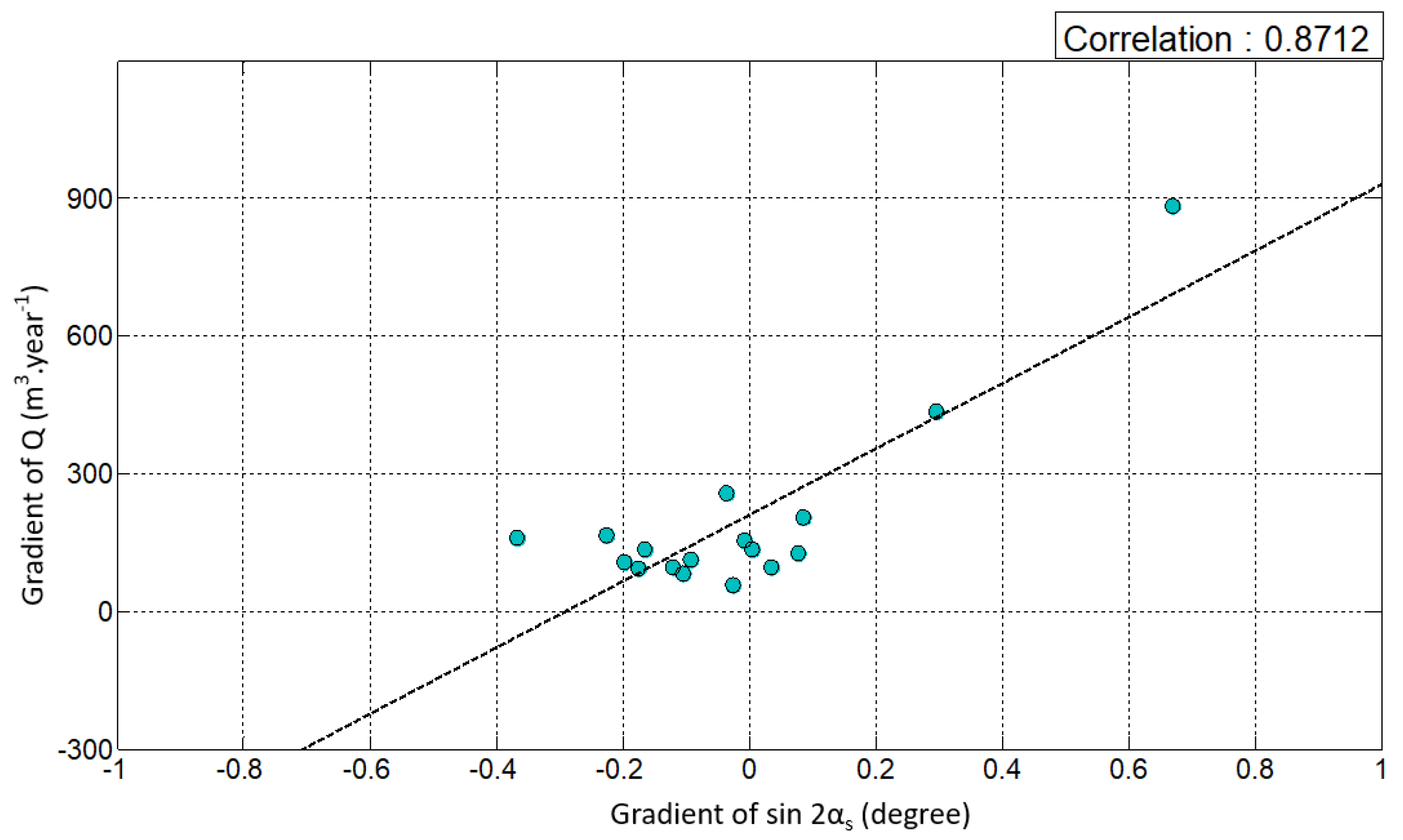
The correlation of longshore sediment transport and the predominant wave’s direction in their gradient is shown in
Figure 11. This result indicates that the longshore sediment transport in this system has a strong correlation with the shoreline angle, showing a satisfactory correlation coefficient 0.8712. Then, the result shows a nearly constant value for the longshore drift potential (
) for this system, i.e., 740.02 m
3/year. The longshore drift potential represents the tendency of longshore sediment transport in this system owing to almost the same wave characteristic. However, the fitting curve shown in
Figure 11 does not pass through the origin (0,0). The reason for this phenomenon is discussed in the next section.
6. Discussion
Although the gradient of
is zero,
Figure 11 indicates that the net flux of longshore sediment drift flows along the shoreline. Such a situation is possible for two cases; a) the shoreline is linearized by the retreat of a control point from the concave shape, and b) the shoreline is concaved from the linear shoreline under a fixed control point. The first and second cases are depicted as shown in
Figure 12a,b, in which the subscript ‘w’ implies the wave angle at the breaking point. The predominant wave direction is considered as the normal angle of equilibrium shoreline.
Many beaches have a concave shape under a static equilibrium state. However, if the shoreline becomes linearized owing to the retreat of control point downstream, the littoral drift can be generated toward the control point as indicated in
Figure 12a. However, Nusa Dua Beach has suffered from the change of wave direction and the consequent generation of littoral drift as depicted in
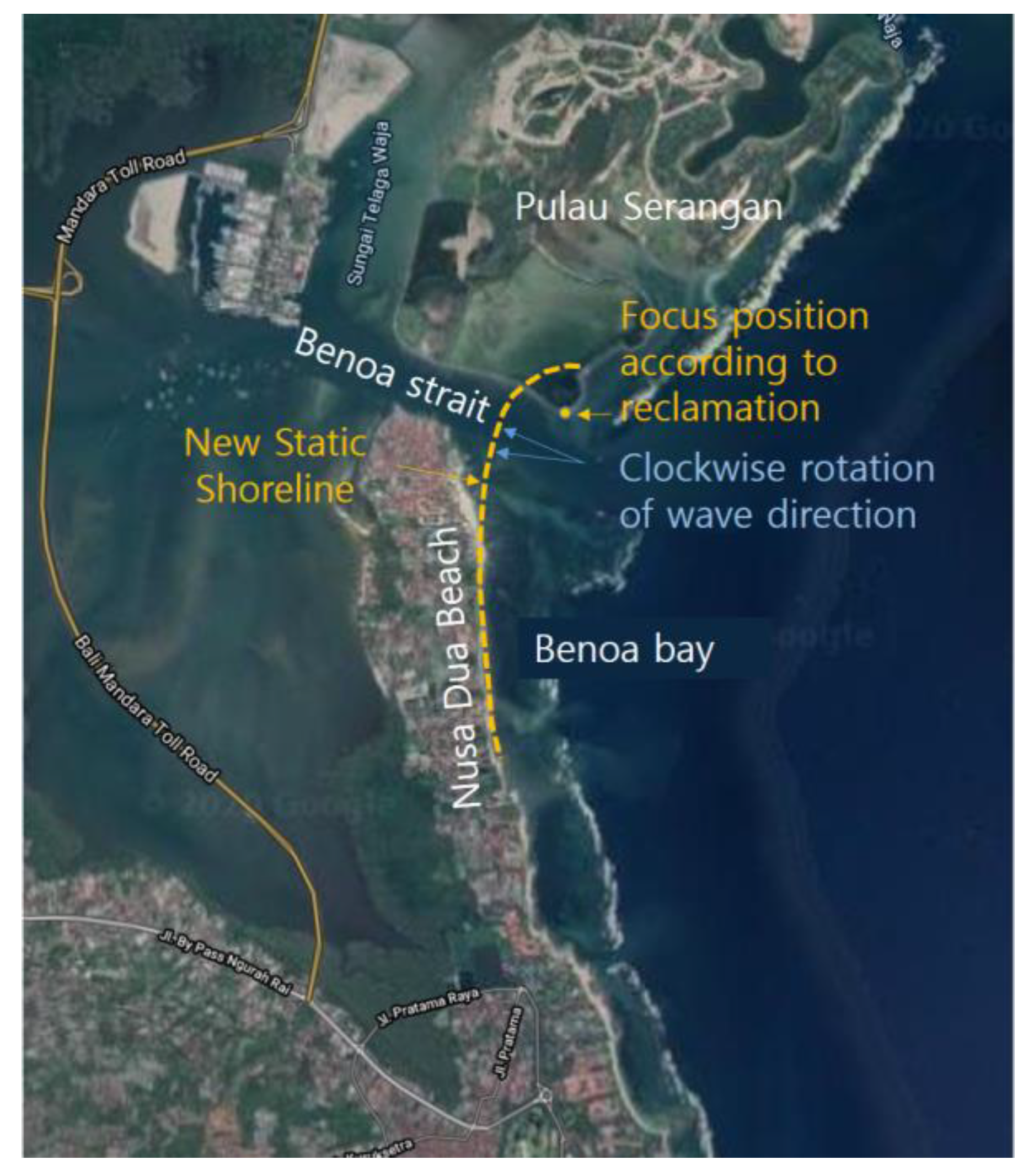
Figure 12b after the reclamation project of Serangan Island located north of the Benoa strait.
Figure 13 shows the equilibrium shoreline estimated by MeEPASoL after reclamation and the rotated direction of dominant wave. In this case, the Benoa strait becomes a sink point of sand losing. Based on this result, Nusa Dua Beach is now classified into the topography-induced dynamic state of allowing a uniform stream of sediment of approximately 110
,
Figure 11. If this is true, however, this dynamic state would not reach the equilibrium state ever due to the presence of Benoa strait to play as a sink. Thus the construction of a jetty at the spit end would is recommended to mitigate such a uniform stream.
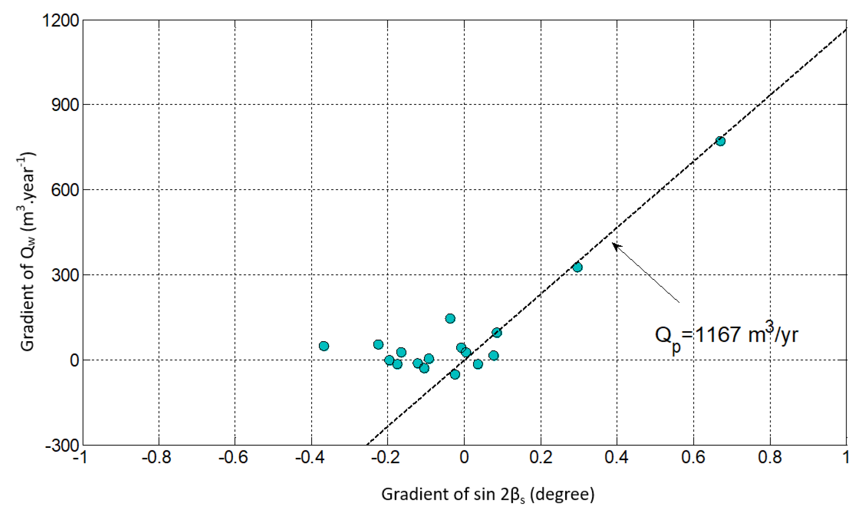
Figure 14 shows the reasonable relationship between the gradient of wave-induced sediment transport
and
after removing the dynamic transport component of 110
. The revised estimation of the longshore drift potential is resulted in 1167
, which is the longshore drift potential representing the level of wave characteristic. The symbol group posed along the zero gradient of Q is taken into account affected by the shoreline rotation owing to groin construction. The groins, which were constructed to control longshore sediment transport, triggered clockwise shoreline rotation from the dominant wave direction.
In the present data analysis, we determined that the littoral cell of the study site has unique longshore transport pattern. Thus, it was considered as one littoral cell although it is composed many subcells divided by natural small headlands or groins. The present methodology shows that Nusa Dua Beach is now suffering from a beach erosion problem owing to the dynamic state of littoral drift directed to an inlet after the reclamation, thereby losing sand into an inner bay.
Furthermore, based on the interaction of the predominant wave direction and the headland of groins as a coastal structure, the shoreline can take a parabolic shape at the equilibrium condition. The shoreline movement and equilibrium condition represent the phase potential line in every sublittoral cell. The shoreline moves from the high phase potential line to the low phase potential line. Then, the predominant wave direction can represent the shoreline orientation in every sublittoral cell.
From the longshore drift patterns analysis, the simulation results show that the longshore sediment transport in this system correlates strongly with the change of predominant wave direction. From this simulation, to reduce the longshore sediment transport, the gradient of the shoreline orientation must also be reduced (smaller gradient of αs gives a smaller gradient of Q). Therefore, all coastal protection activities should be integrated with the coastal zone system. Occasionally, coastal protection strategies aim to protect a few sublittoral cells, and thus coastal structure is designed such that it can reduce the longshore sediment transport in that specific area. Nevertheless, this protection affects the sediment supply system in the adjacent area.
Therefore, a strategic approach can be developed to deal with the longshore sediment transport. To manage the beach erosion owing to the longshore drift, the design of coastal structures should consider the shoreline’s orientation. The designs should consider all sublittoral cells in the system. The position, length, width, distance, and shape of coastal structures affect the shoreline orientation owing to the predominant wave direction, which establishes the equilibrium shoreline condition. Therefore, the sediment budget at adjacent sublittoral cells can be affected. The amount of sediment supply and the sand bypassing method are also essential factor in managing beach conservation.
7. Conclusions
This study aimed to assess beach erosion at Nusa Dua Beach in Bali. To achieve a better understanding of coastal erosion, it was necessary to conduct longshore drift pattern analysis. The results of this study can be useful for future strategic beach management program.
Based on the results of this study, almost all sublittoral cells at Nusa Dua Beach suffered from erosion after the beach conservation project. The longshore sediment transport or littoral drift generated beach erosion in this area. Some groin systems were built to stabilize the longshore sediment transport. Owing to the interaction of predominant waves and the headland of the groin, the beach exhibit the equilibrium shoreline condition. The shoreline moves from the area with a higher phase potential line to that with a lower phase potential line. The simulation of equilibrium shoreline using MeEPASoL gives a satisfactory result for Nusa Dua Beach, and the predicted equilibrium shoreline fits with the satellite image.
In this study, although some sublittoral cells were eroded just a few were deposited, like sublittoral cells 12A and 12C. The simulation result shows a strong correlation between longshore sediment transport and predominant wave direction or shoreline orientation, with the correlation value of 0.8712. This simulation result can be used as the pattern for longshore sediment transport at Nusa Dua Beach. The longshore drift potential () at Nusa Dua Beach was 740.02 m3∙year-1. This longshore drift coefficient represents the tendency of longshore sediment transport based on the shoreline orientation. Sublittoral cell 13 had the highest Qout, therefore, it is neccesary to construct a groin near groin GA2 to cut the phase potential line.
Nusa Dua Beach is classified into the topography-induced dynamic state, allowing uniform stream of sediments of about 110. Furthermore, the revised estimation of the longshore drift potential resulted in 1167 which is the longshore drift potential representing the level of wave characteristic. This was taken into account to be mainly caused by the change of wave direction after the reclamation project of Serangan Island located north of the Benoa strait. MeEPASoL showed that the equilibrium shoreline was clockwise rotated after reclamation and the rotated direction of dominant wave, thus the longshore sediment can be generated toward the Benoa strait.
The design of coastal protection activities should be based on the patterns determined in this study because there is a correlation with the beach morphology condition, especially with the predominant wave direction as the shoreline orientation. The groins, which were constructed to control longshore sediment transport, induced a clockwise shoreline rotation from the dominant wave direction. The littoral cell of the study site has unique longshore transport patterns and is thus considered as one littoral cell, although it is composed of many subcells divided by natural small headlands or groins. The present methodology shows that Nusa Dua Beach is now suffering the beach erosion problem owing to the dynamic state of littoral drift directed to an inlet, thus losing sand into an inner bay.
Furthermore, it is necessary to simulate the effect of the design of coastal protection activities according to the beach morphology and the sediment budget. The balance of longshore sediment transport needs to be considered a reduction in erosion. The shoreline orientation in every sublittoral cell owing to the impact of the coastal structure, should be managed, such that it exhibits an insignificant difference with the adjacent sublittoral cell. Then, the erosion problem can be reduced. Therefore, for the strategic beach management program, the design of coastal structures (length, shape, and width) should consider the impact on all systems, not just in the selected sublittoral cell. The sediment balance in one sublittoral cell will affect the condition of the other area.
This study elucidated the importance of monitoring data in the long term for beach erosion analysis and assessment. Satellite images also provide essential information for conducting shoreline analysis and determining equilibrium shoreline conditions. Furthermore, this study also provided further ideas and research topics in coastal science and engineering. Such ideas can also be generated for improving technology and calculating sediment transport. Moreover, the findings of this study indicate that the plan or design of beach conservation management activities can be simulated to obtain the most effective and efficient strategies.
