1. Introduction
Computer-aided design/manufacturing/engineering (CAD/CAM/CAE) technology is widely used in all manufacturing industries, and the CAD model is the basis of the three-dimensional (3D) shape representation of design results [
1,
2]. In the ship and offshore plant field, 3D CAD models are widely used in all processes including design, procurement, construction, and operation [
3,
4,
5]. 3D CAD models are larger than other 3D models because they include not only 3D shape information, but also diverse engineering information. In particular, 3D CAD models for ships and plants are very large because ships and plants are composed of several millions of parts. Therefore, lightweight models that are smaller and enable fast visualization are frequently used instead of 3D CAD models for visualization of large-sized 3D data [
6,
7].
Lightweight models are mainly composed of triangular meshes.
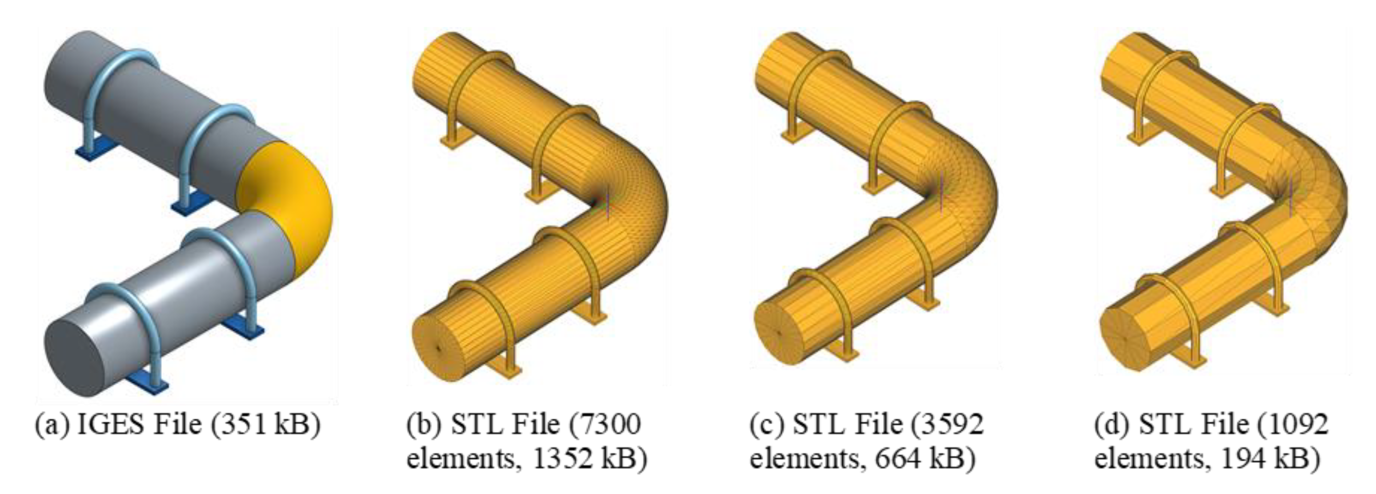
Figure 1 compares 3D CAD and lightweight models. As neutral file formats to store the geometric information of 3D CAD models, initial graphics exchange specification (IGES) and standard for the exchange of product data (STEP) files are frequently used. To represent the shapes of 3D CAD models, the boundary representation (B-rep) method, consisting of topology and geometry, is used. Furthermore, in the B-rep model, curves and surfaces are mainly described in accordance with the expression of non-uniform rational B-spline (NURBS).
Figure 1a shows a 3D CAD model, and
Figure 1b–d shows the results of converting it to triangular mesh models.
Figure 1a shows the size of the 3D CAD model saved in IGES format, and
Figure 1b–d shows the size of the triangular mesh models saved in stereolithography (STL) format. If the shape is curved or has an arc, the 3D CAD model has an error with the lightweight model. When the shape of the 3D CAD model is divided into many triangles, this error decreases and the lightweight model becomes closer to the actual shape. However, if it is divided too densely, the data of the lightweight model increases, resulting in large memory use and low visualization performance. When the model is saved as an STL file consisting of triangular mesh, the file size is determined according to the density of the triangular mesh. The STL file can have a small size if the triangular meshes are generated in a low density.
When the 3D design of a ship or offshore plant is completed, the lightweight model for the ship and offshore plant is created through conversion from a 3D CAD system to a neutral model, tessellation, and lightweight model configuration [
8]. The design shapes of the ship and offshore plant generated in many 3D CAD systems are saved as a neutral file (neutral 3D CAD model) such as STEP and IGES. Then, triangular meshes are generated from the neutral model using a converter, and then the lightweight model is configured using additional information. The created lightweight model is used in conjunction with a separate database that contains information about design, production, and logistics.
Due to the nature of plant construction, design changes inevitably occur, and the 3D CAD model must be converted to a lightweight model whenever a design change occurs. The lightweight files are managed in a separate server. Furthermore, even a lightweight file requires a size of several GB to represent a large plant structure. Consequently, it may take considerable time to transmit the lightweight file from a personal computer (PC) to a server through the network. Thus, it is necessary to reduce the data size for fast transmission [
9,
10].
A ship or offshore plant structure is composed of thin plates, beam structures, pipes, and equipment. They use the same shapes repetitively and, unlike mechanical parts, they do not have fillets or chamfers at the edge. Hence, the top and bottom parts of thin plates are symmetrical in shape. This paper proposes a method of reducing a lightweight file using the characteristics of each part type comprising the structure. The proposed method is applied for the conversion of 3D CAD models designed for structures of ships or offshore plants into a lightweight format.
The rest of this paper is organized as follows.
Section 2 discusses related works.
Section 3 proposes a method of reducing lightweight files for ship and offshore plant structures.
Section 4 presents the system implementation and experiment results. Finally,
Section 5 presents conclusions.
2. Review of Related Studies
Lightweight models generally represent shapes using triangular meshes. The representative file formats include Jupiter Tessellation (JT), 3D extensible markup language (3D XML), virtual reality modeling language (VRML), extensible 3D (X3D), and universal 3D (U3D). STL and Wavefront object (OBJ) files, which are often used in 3D printing, can also be used as lightweight files [
11]. X3D [
10] and U3D are used to quickly visualize a 3D CAD model on the Internet. JT [
12] is a format that has been standardized by ISO 14306 [
13] and used often in the ship and offshore plant industries. Methods to reduce the size of lightweight files can be largely classified into simplifying the shapes of the parts comprising the ship and offshore plant and reducing the size of lightweight files by improving file structure.
Methods to simplify the shapes of parts include polygon-based simplification for mesh models [
14,
15] and feature-based simplification based on B-rep (boundary representation) or feature-based models [
3,
16,
17]. Polygon-based simplification, mainly used in computer graphics, aims to generate a low-resolution model by reducing the number of triangular elements comprising triangular meshes. Feature-based simplification rearranges the features according to importance and removes low-importance features to simplify the model. Kang et al. [
3] and Kwon et al. [
17] presented criteria for evaluating the importance of features by considering the characteristics of plant equipment. Kwon et al. [
8] suggested a method of simplifying features by type after classifying the features of lightweight models for offshore plant structures by type.
The size of a lightweight file varies according to the stored triangular structure, storing method (text or binary), and compression method. The file size required for all 3D shapes can be reduced not only by representing them as triangles, but also by using B-rep primitive in hybrid. The basic shapes such as box, cylinder, sphere, cone, and pyramid are smaller in size than representing them using triangular meshes, because not only the parameter information, but also information such as dimension and position is stored. With regard to this, Nguyen et al. [
18] proposed a method for reducing the size of lightweight models by representing a triangular mesh model and a B-rep model in hybrid. Furthermore, Eigner et al. [
19] suggested a method for using the JT file together with an XML file that contains additional information in order to improve the utilization of the JT file. Kwon et al. [
20] proposed adaptable lightweighting procedures of 3D CAD models considering various semantics during the lifecycle of plants. Wen et al. [
21] suggested a method to access Web3D content quickly using lightweight progressive meshes. Wang et al. [
22] used a compressive sensing-based 3D model compression method to rapidly compress server-side models in order to reduce the model space.
Figure 2 shows general lightweight models in comparison with a lightweight model using the hybrid method. When the shape of
Figure 2a is converted to a lightweight model (
Figure 2b), the hybrid method saves the cylinder, which is a simple curved surface, in B-rep format, while saving the other two curved surfaces as triangular meshes.
Figure 2c shows the hybrid model, which can reduce the file size but is applicable to some simple shapes only. If complex shapes are saved in B-rep format, additional time is required to restore the triangles in the visualization process. Moreover, the visualization quality can be degraded because of connectivity mismatch (
Figure 2d) with adjacent faces depending on the number of nodes generated at the boundary between different faces, which necessitates additional density matching.
3. Minimizing the Size of a Lightweight File Considering the Characteristics of Ship and Offshore Plant Structures
3.1. Triangular Element Storage Structure of General Lightweight File
A triangular mesh is a set of three vertexes and triangular elements in normal direction as shown in
Figure 3. The normal direction is used to render shapes realistically and to distinguish the inside and outside.
There are three general methods for representing structures for storing triangles in a lightweight model. The first method is to represent them using the coordinates of three vertexes comprising the triangle. The representative example is the STL file [
23], which has a very simple file structure but in which the accurate normal information is not stored at each vertex, and multiple vertexes exist at one position. In
Figure 4, to represent the triangular element E1, vertexes V1, V2, and V3 are written, and then the normal directions for them are written (
Figure 4b). The second method is to write the coordinate value and normal direction for each vertex, and a triangle is represented by writing the numbers of the stored vertexes (
Figure 4c). The representative file format is the OBJ file [
24], which can reduce the file size because only one vertex exists at each position that has one normal direction. The last method is to represent a structure as a stripe structure by connecting the vertexes sequentially (
Figure 4d). The representative example is the JT file format, which can have a large file size because it can have many duplicate nodes.
To compare file sizes for the triangular mesh composed of five triangles and seven vertexes as shown in
Figure 4a, if the coordinates are stored in a float type (4 bytes), the size of the STL file type is 240 bytes and the size of the OBJ file type is 228 bytes. In the case of the JT file type, the coordinates are stored in a two-strip structure, and the file size becomes 264 bytes.
3.2. Lightweight File Size Minimization Process
The lightweight file minimizing method proposed in this study is to classify part types by reflecting the characteristics of ship and offshore plant structures and minimizing and storing the data according to each type. For visualization, the 3D shape must be represented as a triangular mesh and the restoration time must be reduced by decreasing the computational scale required for restoration. Ship and offshore plant structures are composed of thin shell structures, beam structures, pipes, and equipment. The top and bottom faces of most shell structures have the same shapes because they have almost no fillet and chamfer. The beam structure and pipe generally have a long shape with the same cross-sections. Furthermore, shapes of the same size are placed repeatedly. To reflect these characteristics, this study classified parts into the following four types: same type, mirroring type, basic type, and free type. In addition, the lightweight file size was reduced by storing minimum information that can represent the shape of each type.
Figure 5 shows the overall process for minimizing the lightweight file size. The triangle information of parts is stored according to the type of the shape. First, the type of the part to be stored is classified. The same type refers to the case where the shape is completely identical to that of a stored part. A transformation matrix is saved to use a copy of a stored part. If the part is not the same shape, second, whether the part has a mirror shape is determined. If it is a mirror shape, the symmetry plane and the direction vector are stored. Next, it is determined whether the part is a basic type such as cone and elbow. In this case, the information for restoring the shape in accordance with the face and angular shapes that can represent the basic type is stored. Finally, unclassified shapes are specified as free type. The free types are classified again by face type. The faces of mirroring type and basic type are also classified, and the data are stored in accordance with each face. If the face is a mirroring face, the standard edge and direction vector are stored. Faces like an arc are classified as basic face type. The unclassified faces are stored in the same way as in the previous method.
3.3. Same Type Part
Ship and offshore plant structures have many parts with the same shape. The five types in
Figure 6 are the same types. In this case, a transformation matrix to copy the first type is stored for the other four shapes. The same type here means that the size and shape are fully identical. The transformation matrix is a homogeneous transformation matrix consisting of 16 real numbers, but only 12 real numbers need to be stored because it is rigid body translation here. One type has 136 elements and 172 vertexes in the case of the OBJ type. This requires 5760 bytes; however, this decreases to 48 bytes if only the transformation matrix is stored for the same types. The transformation matrix value is stored for four identical types, and for the one original type, the mirroring type and the free type to be explained in the following section are determined and the data are stored accordingly.
3.4. Mirroring Type Part
Ships and offshore plant structures are mainly composed of beam types, thin plates, and pipes. As shown in
Figure 7, most types are mirroring types, whose two opposite faces are identical. Therefore, the shape of the other face can be restored by using the information of one face. The criteria for the mirroring condition of parts are as follows:
Two planes facing each other have opposite normal directions
Two planes satisfying the condition 1 have the same area
The straight line connecting the centers of two planes satisfying the condition 2 are parallel to the normal direction of the two planes.
For data storage, the vertexes and triangle information for only one of the two mirroring faces are stored, and then the direction of the line interconnecting the centers of the two faces is stored. To restore the total shape, the adjacent face of the stored face is restored first by moving the stored face for the direction vector and then setting the normal direction opposite to that of the stored face. The side faces are restored using the edge information of the two stored end faces. The edge extraction process in the side face restoration process requires additional calculation. Hence, to reduce the restoration time to the maximum, the information of boundary edges is also stored. Since the normal direction of the vertexes for the mirrored face is identical to the direction of the face, the direction of the face is used for restoration without storing the normal direction. The normal direction for the nodes of the side faces excluding the mirrored face is stored at each vertex and then used for restoration.
Figure 8 shows an L-beam shape composed of 32 elements and 46 vertexes. The reference face is shown in
Figure 8b, which is composed of 7 elements (E1–E7) and 9 vertexes (V1–V7), and has 5 edges. The normal values are not stored at the vertexes, but the normal directions for the side faces are stored when the edge data are stored. For example, edge C1 is composed of vertexes 1 and 2, and edge C2 is composed of vertexes 2, 3, 4, 5, 6, and 7. The normal direction of vertex 2 of C1 has the same coordinates as those of the vertex 2 of C2, but the vertexes have different normal directions. Finally, the vector coordinates for the two mirrored faces are stored. When the conventional method is used, the data size is 1488 bytes (
Figure 8a), but the data size becomes 428 bytes when the method proposed in this study is used (
Figure 8b).
3.5. Basic Type Part
The basic types generally refer to box, pyramid, prism, cone, cylinder, and elbow. Box, prism, and cylinder shapes can be represented using the mirroring type explained in the previous section. As shown in
Figure 9, the elbow and cone shapes have repeated circular cross-sections, which are classified as basic types in this study. In the case of elbow, the vertex data for the edges of one face are stored, and for the next face, the transformation matrix is stored to copy the first face and use it for restoration. Since elements are generated in uniform intervals, the transformation matrix for the following face is the same, and only the number of divisions needs to be stored. The process of restoring the triangular elements consists of configuring the vertexes of the next layer by multiplying the vertexes of the circle by the transformation matrix, and then combining them in a zigzag form. For the cone, the vertexes of the bottom face and the vertexes of the end points are stored. In the case of the truncated cone, the vertexes for the bottom and top faces are stored. The two end faces of the cone and elbow shapes are circles, for which the center coordinates of each are stored. In the restoration process, the side faces are restored by connecting the vertexes of two edges in a zigzag manner, and the centers of the two end faces are connected with the points of the edges to configure a triangle.
Figure 10 shows the examples of elbow and truncated cone. The elbow in
Figure 10a has 10 vertexes on the edges of circles and one center of the circle. One normal direction is stored because the vertexes of the edges have the same normal direction, and the coordinates of each vertex are stored. The number of divisions is four. Unlike other shapes, the elbow requires a computation process of multiplying the matrix to calculate the coordinates and normal direction of the vertexes of the next layer. However, the elbow shape has a very large effect of file size reduction because it can be represented by many triangles.
Figure 10b shows a truncated cone, for which information about the bottom and top circles is stored by storing the coordinates of the vertexes and one normal direction, because the two faces have the same normal direction.
3.6. Free Type Part
All the other shapes (i.e., excluding those explained above) correspond to free type. Ships and offshore plant structures have various types of reinforcements. As shown in
Figure 11, parts having holes, fillets, and chamfers are not classified as mirroring type. Furthermore, a large number of triangles are generated when there are local shapes such as holes, fillets, and chamfers. In the case of free type parts, triangle data are stored in the face unit. Faces are classified into mirroring face, basic face, and general face.
One mirroring face is composed of four edges, and the two edges facing each other have the same shape. In the case of two opposite edges, one edge can be moved using a vector without rotation. The basic faces include the faces of elbow and cone shapes, as with the basic type explained above; arcs are also basic type.
Figure 12 shows mirrored faces. The conditions for mirrored faces are as follows:
One face is composed of four edges
Two opposite edges have the same shape and length
The end points of two edges are apart by the same distance
For mirrored faces, as shown in
Figure 12b, the vertexes and vector value for one mirrored edge are stored. The shape in
Figure 12 has a size of 336 bytes when stored as the conventional OBJ type, but can be represented with 132 bytes by applying the mirroring type. To restore the triangular elements using this information, the vertexes of the edge are moved by the vector value and then triangular elements are configured in a zigzag manner without any computation.
Figure 13 shows the basic type faces. If two opposite edges have different shapes but have the same number of vertexes, the data of the vertexes of the two edges are stored (
Figure 13a). For the face in
Figure 13b, the data of the nodes and sharp points of the edges are stored. For circular shapes, the center and boundary nodes’ data are stored (
Figure 13c,d).
3.7. Normal
If the classified face is flat, the triangular elements of the face have the same normal direction. Therefore, in this case, only the normal direction of the face needs to be stored. Hence, if the face in
Figure 12 is flat, only the normal direction of the face can be stored instead of the normal directions of five vertexes as shown in
Figure 14. The data size decreases from 132 bytes to 84 bytes.
For curved shapes, there are largely two methods to reduce the normal data. The first is to reduce the size of the
x,
y, and
z values, for which 12 bytes are used when stored as float type. A float type variable has six or seven valid digits, but the normal direction does not need to be represented as precisely as this. QSplat [
25] is a structure used to visualize large-sized points and can store the coordinates, normal direction, and color information in 48 bits (8 bytes), and the normal information can be stored in 14 bits. Even though the number of valid digits is decreased, there is no problem in visualization. However, a process of converting the bit unit to
x,
y, and
z float type is required for visualization.
The second method is to calculate the normal direction when the file is read without storing the normal direction. In this case, the normal values of elements are used after the elements sharing the vertexes are found. Thus, the data size decreases because the normal directions are not stored, but calculation time is additionally required and the normal calculation result may contain an error. In this study, these two methods were not considered because the 3D shapes of offshore plant structures consist mostly of flat faces.
3.8. Lightweight File Format
The lightweight file format proposed in this study is shown in
Figure 15. Only the minimum information about the shape is stored. The attributes of parts (i.e., name, type, dimensions, and material) may be included in the lightweight file if necessary. The shape information corresponding to the type of each part is stored in part unit by default. For the same types, the part ID of the same type and a transformation matrix are stored. For the mirroring type, the mirrored reference face and direction vector value are stored. In addition, the information about the face is stored as mirroring type, basic type, or free type. The basic types are elbow and cone shapes, but a type can be added if there is an additional basic type. The free type is stored in face unit, and the free type is the case where all the data are stored in the same way as in the conventional method.
4. Implementation and Experiment
To verify the results of this study, three models provided by ‘S’ shipbuilding company in Korea were tested. The specifications of the PC used for this test were Intel i9-9900K CPU, Samsung 32 GB memory, and Samsung SSD M.2 NVMe storage. For the development tool, Microsoft Visual Studio 2015 (C++) was used.
Figure 16 shows an L-shaped beam composed of 12 faces. It has a size of 5760 bytes when 148 triangles and 166 vertexes are stored. If the data are stored in face unit, there are eight mirrored faces, seven of which are flat faces. It is stored as a free type with data size of 3196 bytes.
Figure 17 shows a hook-up model composed of 11 pipes and support parts. They are classified into one free type, two mirroring types, seven same types, and one basic type (elbow). The file was stored in a 30 kB binary file. To compare the file size for the results of this study, the same triangular elements were stored in an STL file and a JT file of the binary type. If this is stored in an STL file, the size is 357 kB, and if it is stored in a JT file, the file size is 83 kB. The JT file is a compressed format. For size comparison, the files were compressed using Zlib [
26] in this study, in which case the file size becomes 14 kB, which is 8.4% of the STL file size and 16.9% of the JT file size.
Figure 18 shows an offshore plant structure composed of 118 parts. If this is configured as a lightweight model, it is composed of 64,868 triangular elements, which are classified into nine free types, 18 mirroring types, 88 same types, and three basic types. There are many same types because of the repetitive structures typical of plant structures. Furthermore, think plates and many H beams were classified as mirroring type.
The STL file size is 3618 kB, and the result of this study is 223 kB. The JT file size is 720 kB, and it becomes 106 kB when compressed. The file size is 6.2% and 14.7% of the STL and JT file sizes, respectively. The method proposed in this study simplifies the shape and stores the minimum information required for restoration of the shape. Therefore, additional time for restoration may be required.
Table 1 compares the lightweight file sizes and loading times for test cases between the proposed method and other file formats (JT and STL). In
Table 1, ‘Loading time’ indicates the time required to read the file and the time required to create a triangle mesh for the shape using the information on repetitively used or symmetrical shapes stored in the lightweight file. As shown in
Table 1, the time is shortened compared to reading other file types. This is because the shape can be configured by combining the stored data simply with no additional complex computations for restoration.
Conventional methods to store a lightweight model can be categorized into the following three categories: the method to store a 3D shape as triangular mesh [
23], the method to store only parameter values needed to define primitives which are used to represent a 3D shape [
12], and the method to store both triangular mesh and B-rep elements [
18]. The first method requires no additional work other than creating a triangular mesh from a 3D CAD model, but the file size is large. In the second method, the file size required to save a 3D shape is small, but shape representation using primitives is limited in coverage, and it takes considerable time to restore a triangular mesh during the visualization process. The third method takes considerable time to restore a triangular mesh from B-rep elements in the visualization process, and the boundaries of triangle elements and B-rep elements must be adjusted to match each other. The method proposed in this study can reduce the file size for shipbuilding and offshore structures in which the shapes facing each other are the same or the same shape is used repeatedly. However, when saving a lightweight model, it is necessary to check the shape to determine whether there are such patterns. In the case of mechanical structures, they do not have many such patterns and, thus, the effect of reducing file size is small.
5. Conclusions
A method of reducing the lightweight file size for ships and offshore plant structures was proposed. Ships and offshore plant structures are mainly composed of thin cell structures, beam structures, and pipes. The top and bottom faces of most shell structures have the same shape, because they have almost no fillets and chamfers. The beam and pipe structures are long shapes with the same cross-sections in general. Furthermore, parts with the same-sized shapes are placed repeatedly. The parts were classified into mirroring type, same type, and free type by reflecting these characteristics, and the file size was reduced by storing the minimum data required for representing shapes. Furthermore, when parts could not be classified into specific types, the data size of each face was reduced by classifying faces into types. In the proposed method, the size of a lightweight file is not related to the shape size and is affected by the shape pattern. Consequently, the experiment results showed that the file size decreased to less than 10% of the STL file size and less than 20% of the JT file size. In addition, the edge data were stored for mirrored structures to shorten the time for shape restoration, and the same types could be restored simply by copying.


