1. Introduction
For mooring a ship on the sea to prevent unexpected movement, specific equipment, such as anchors, anchor chains, and ropes, are needed. Therefore, when designing a ship, it is necessary to determine the appropriate specifications of these equipment. Here, specification refers to the weight of anchors, length and diameter of anchor chains, number of towlines and mooring lines, and breaking load. Furthermore, the specification of these equipment should be determined by considering the drag force due to the current and wind acting on the ship. However, as it is not efficient to calculate the drag force whenever an equipment is designed, the specifications of the equipment are generally determined by referring to the equipment number of each ship.
The formula for calculating the equipment number, which was developed several decades ago, is provided by the classification society. Although there have been several detailed supplements and revisions, there has been no change in the structure of the basic formula. However, owing to changes in the marine environment; the development of various types of ships, such as container ships, liquefied natural gas carriers (LNGCs), and drill ships; and the emergence of new technologies, it is necessary to verify whether the current formula for equipment number calculation is still suitable. Therefore, in this study, the suitability of the existing equipment number formula was verified, and a modified coefficient is proposed for each term.
2. Equipment Number Calculation and Holding Power of Mooring Equipment
2.1. Equipment Number Calculation
The equipment number formula is a standard equation used to determine the specifications of mooring facilities. This equation is a function of the area above and below the water surface. The Korean Register of Shipping (KR), American Bureau of Shipping (ABS), and other major classifications belonging to the International Association of Classification Societies (IACS) use the same equation for equipment number calculation and equipment number table. The equipment number formula that was considered in this study is as follows [
1].
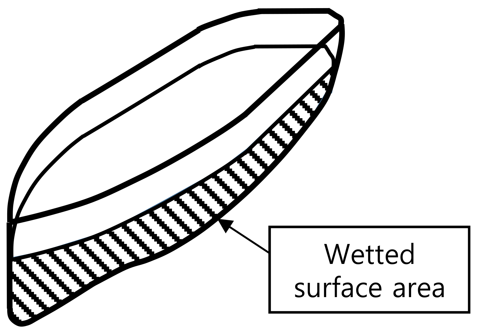
The first term,
refers to the area of the ship below the water surface on which the current force acts, i.e., a value proportional to the wetted surface area as shown in
Figure 1. Here,
is the displacement at the summer load line, and its dimension is volume. By multiplying
to the power of 2/3, the dimension of the volume was changed to the dimension of the area.
In the second term,
denotes the area that receives the wind force along the longitudinal direction of the hull above the water surface, i.e., a value proportional to the longitudinal projected area. Here,
is the width of the hull and
is defined as follows:
where
is the freeboard amidships from the summer load waterline to the upper deck in meters, and
is the height at the centerline of the superstructure or deckhouse having a breadth greater than
. The variables of second term are shown in
Figure 2.
In the third term,
indicates the lateral projected area subjected to the lateral wind force and calculated as follows.
Here, is the height of the superstructure, deckhouse, or trunk, whose breadth is greater than and height is greater than 1.5 m, and represents the length of the superstructure.
2.2. Holding Power of the Mooring Equipment
When a ship is designed, the equipment number can be calculated using Equation (1). Based on this equipment number, all specifications of mooring equipment, such as anchors, anchor chains, tow, and mooring lines, can be determined using the standard table provided by IACS [
2]. Therefore, the holding power of anchors and anchor chains can be calculated using the following equation provided by KR [
3].
The first term in Equation (4) represents the holding power of an anchor, whereas the second term denotes the holding power of anchor chains.
and
are the holding power coefficients of the anchor and anchor chain, respectively. These coefficients have different values depending on the seabed condition and are summarized in
Table 1.
In Equation (4), and are the weights of the anchor and anchor chain per meter in seawater, respectively. As the density of the anchor, made of iron, is 7874 kg/m3 and that of seawater is 1025 kg/m3, the ratio of the weight reduced by buoyancy relative to the original weight of iron is 1:0.131. Thus, the weight in seawater can be obtained by multiplying the weight in air by 0.869. Moreover, the gripping force was calculated under the following conditions.
The ratio of water depth and draft was 1.1, which is similar to the conditions for the drag force calculation.
Extra high-strength steel (Grade 3), which is generally used in shipyards for anchor chains, was utilized.
The coefficient of mud condition was considered to be Ka = 2 and Kc = 0.6 for assuming the most conservative situation.
First, the equipment numbers for three oil tankers, two LNGCs, and three container ships were calculated using Equation (1), and anchors and anchor chains were determined by referring to the calculated equipment numbers. Then, the holding power of anchors and anchor chains were calculated using Equation (3). The calculation results are summarized in
Table 2.
3. Drag Force Calculation
To verify whether the specifications of the selected mooring equipment are appropriate, the holding power of the mooring equipment and drag force acting on the ship must be compared. Therefore, in this section, the drag force acting on each ship is calculated.
Mooring equipment is selected based on the equipment number calculation. This mooring equipment includes not only anchors but also wire ropes used to tie up ships in ports. Therefore, it is reasonable to assume that the equipment number calculation formula is generally derived based on when the ship is anchored or moored near a port, so that Oil Companies International Marine Forum (OCIMF), which refers to the ship moored in port, is used to calculate drag force.
3.1. Wind Force Calculation
The drag force mainly consists of the wind force and current force. According to Oil Companies International Marine Forum (OCIMF), the wind force acting on the tanker can be calculated as follows [
4,
5].
Equations (5) and (6) are used to calculate the longitudinal and lateral wind forces, respectively. Here,
θ is the angle of attack,
is the density of air, and
is the wind speed. The magnitude of
θ is measured counterclockwise with the stern side at 0°. As shown in
Figure 3,
is the front projection area, and
is the side projection area above the water surface.
The coefficient,
in Equations (5) and (6) are well defined in the documents provided by OCIMF [
4,
6].
Figure 4a shows the graph of the longitudinal wind coefficient,
, for an oil tanker provided by OCIMF. In
Figure 4a, the solid line that divides into the cylindrical bow and conventional bow represents the coefficient for the ballast state, and the dotted line represents the coefficient for the fully loaded state. A cylindrical bow indicates a U-shaped bow, whereas a conventional bow indicates a V-shaped bow.
is the transverse wind coefficient.
Figure 4b shows the graph of lateral wind coefficient for an oil tanker provided by OCIMF. Here, the solid and dotted lines represent the values for the ballast state and fully loaded state, respectively.
3.2. Current Force Calculation
According to OCIMF, Equations (7) and (8) are used to calculate the longitudinal and lateral current forces acting on the tanker, respectively [
4].
Here, θ is the angle of attack, is the density of seawater, is the speed of the current, is the length between the perpendicular, and is the draft.
The current coefficient,
C, increases as the ratio between the depth and draft decreases owing to the shallow water effect.
is the longitudinal current force coefficient, and
Figure 5a shows the graph of
for an oil tanker (provided by OCIMF) when the ratio of water depth and draft is 1.1. In
Figure 5a, the solid and dotted lines represent the values for the cylindrical bow and conventional bow, respectively. OCIMF provides the same graph even when the ratio of water depth to draft is 1.2, 1.5, 3.0, 6.0, or higher. Similarly,
is the transverse current force coefficient. For various ratios of depth and draft, a graph of the transverse current force coefficient for oil tankers (provided by OCIMF) is shown in
Figure 5b.
3.3. Drag Force Calculation
The wind and current acting on the ship were calculated using Equations (5)–(8). As shown in
Figure 6, ships that were fixed using anchors naturally face the current direction.
Accordingly, the following assumptions were made to calculate the drag force acting on the ship due to the wind and current [
5,
6,
7].
Current and wind comes from the front of the ship.
The angle of attack of the wind is inclined by approximately 5° from the front of the ship owing to the yaw movement caused by fish tailing instability.
The oil tanker is in the fully loaded state and has a conventional bow.
The ratio of water depth and draft is 1.1 for assuming the most conservative situation.
Based on these assumptions, the wind and current force were calculated using Equation (9).
Here,
and
are the current and wind forces, respectively, which were assumed to act from the head of the ship as described in the assumptions; thus,
,
, and
were considered. Additionally,
was considered because the wind force had a slight change in direction compared with the current. Moreover, it was assumed that the angle of attack was approximately 5° away from the longitudinal axis/stem of the ship due to fishtailing instability. Therefore, Equation (10) can be obtained by substituting these changes in Equation (9). Here, 180 and 175 refer to the angle of attack of wind or current. As
. is zero, it was eliminated in Equation (10).
Equation (11) was obtained by substituting Equations (5)–(7) in Equation (10) and was used to calculate the drag force on three oil tankers, two LNGCs, and three container ships. The coefficient,
C, for oil tankers is shown in
Figure 4 and
Figure 5. However, the coefficients,
C, for LNGCs and container ships are confidential values. These values were used in the actual calculations at the shipyard with the cooperation of Daewoo Shipbuilding and Marine Engineering. The calculation results are shown in
Table 3.
and
were considered to be 2.5 and 25 m/s, respectively, which were the conditions for deriving the equipment number formula.
4. Verification of Equipment Number Calculation
Table 4 shows the holding power,
p, drag force,
F, and their ratio.
As the holding power, p, must be greater than the drag force, the p/F ratio must be greater than 1. This value is between 1.7 and 3.0 for all types of ships.
For oil tankers, the p/F ratio is designed to be between 1.7 and 2.2. Similarly, for LNGCs, which have similar hull shapes, the p/F values are not significantly different from those of oil tankers. However, in the case of container ships, the block coefficient of the hull is not relatively large compared with that of oil tankers and LNGCs. Thus, the drag force, F, is relatively small. Therefore, the p/F value is designed with a larger value compared with other types of ships. This suggests that the anchor and anchor chain specifications selected for container ships are excessive compared with other types of ships. In other words, the current equipment number formula is optimized for tankers. Therefore, it is more reasonable to use an optimized equation based on the type of ship rather than using the same equation for all ships.
If it is assumed that anchoring is performed offshore, another calculation method should be used rather than the formula provided by OCIMF, which will calculate the drag force acting on the ship differently. Moreover, if we consider high-grip anchors, the estimated holding power will be increased. On the other hand, if the larger ratio of water depth is considered, the estimated holding power will be decreased as the drag component of a catenary mooring line decreases at the seabed. These assumptions will vary the coefficients of equipment number formula.
However, since the important factor in this study is the comparison between different types of ship, the fact that the specifications of the anchor and anchor chain are excessively designed in a ship with a smaller block coefficient, such as container ship, will not change.
5. Modified Coefficients of Equipment Number Formula
5.1. Analysis of Coefficients of Equipment Number Formula
Equation (11) can be used to calculate the drag force applied to the moored tanker. In Equation (11), all coefficients and variables except
,
, and
, which is decided based on size of the ship, were specified according to the assumptions described in
Section 3.3:
.
These values are substituted into Equation (11) and arranged as shown in Equations (12) and (13).
To change the variable in the first term of Equation (13) into
, the relationship between
and
was summarized for three types of tankers as shown in
Table 5.
Equation (15) can be obtained by substituting Equation (14) into Equation (13).
By comparing Equation (1), which is the equipment number formula, with Equation (15), it can be observed that the coefficients of the terms inside the parentheses are similar to the coefficients of the equipment number formula, i.e., 1, 2.0, and 0.1. Therefore, it can be inferred that the current equipment number is the value obtained by dividing the drag force, F, by 182.
5.2. Analysis of Modified Coefficients
Considering that the drag force,
F, acting on the tanker is calculated using Equation (15) and the coefficients of each term inside the parentheses are 1, 2.1, and 0.1, the equipment number formula for the tanker can be modified as shown in Equation (16).
Meanwhile, the coefficient for calculating the drag force, F, acting on the LNGC can be defined as follows [
4]:
.
Equation (17) can be obtained by substituting these coefficients into Equation (11).
The coefficients of the terms inside the parentheses in Equation (17) are 1, 2.2, and 0.1. Therefore, the equipment number formula for LNGCs can be modified as shown in Equation (18).
Finally, the coefficients for calculating the drag force, F, acting on the container ship can be defined as follows: .
Equation (19) can be obtained by substituting these coefficients into Equation (11).
The coefficients of the terms inside the parentheses in Equation (19) are 1.1, 1.0, and 0.1. Therefore, the equipment number formula for a container ship can be modified as expressed by Equation (20).
5.3. Verification of Modified Coefficients
The equipment number was calculated using the modified coefficients to verify its suitability. Based on the equipment number, the mooring equipment was determined, and the holding force,
p, of the new anchor and anchor chain was calculated and compared with the drag force,
F. The calculation results are listed in
Table 6.
According to
Table 6, for tankers and LNGCs, the change in equipment number is not significant. However, for container ships, the equipment number decreased by approximately 23% on average. Therefore, the mooring equipment specification can be lowered by 2–3 grades. Furthermore, it can be observed that the ratio of
p and
F also decreases from 2.7 to approximately 2.1, which is similar to that of other types of ships.
6. Conclusions
In this study, the suitability of the equipment number formula was verified. First, the formula for calculating the drag force acting on the ship due to the wind and current was derived and compared with the equipment number formula. From this process, the significance of each coefficient in the equipment number formula was analyzed.
Additionally, the holding power of the anchor and anchor chain, which were selected based on the equipment number and drag force acting on the ship, were compared to verify the suitability of the equipment number formula for each type of ship. This revealed that the specification of mooring equipment for a relatively new ship type, such as a container ship, can be overdesigned as the equipment number formula was derived based on tankers. Therefore, modified coefficients were proposed for the equipment number formula for other types of ships, such as container ships. In conclusion, if the coefficients and drag force calculation formula for a new type of ship are known, it is possible to derive a more accurate equipment number formula.


