This section discusses the types of loads and the load combinations acting on the LNG piping system. The allowable stresses on the piping are summarized using load types defined by the ASME regulations. Moreover, the stress intensification factor (SIF) is calculated according to the shape of the curved pipe.
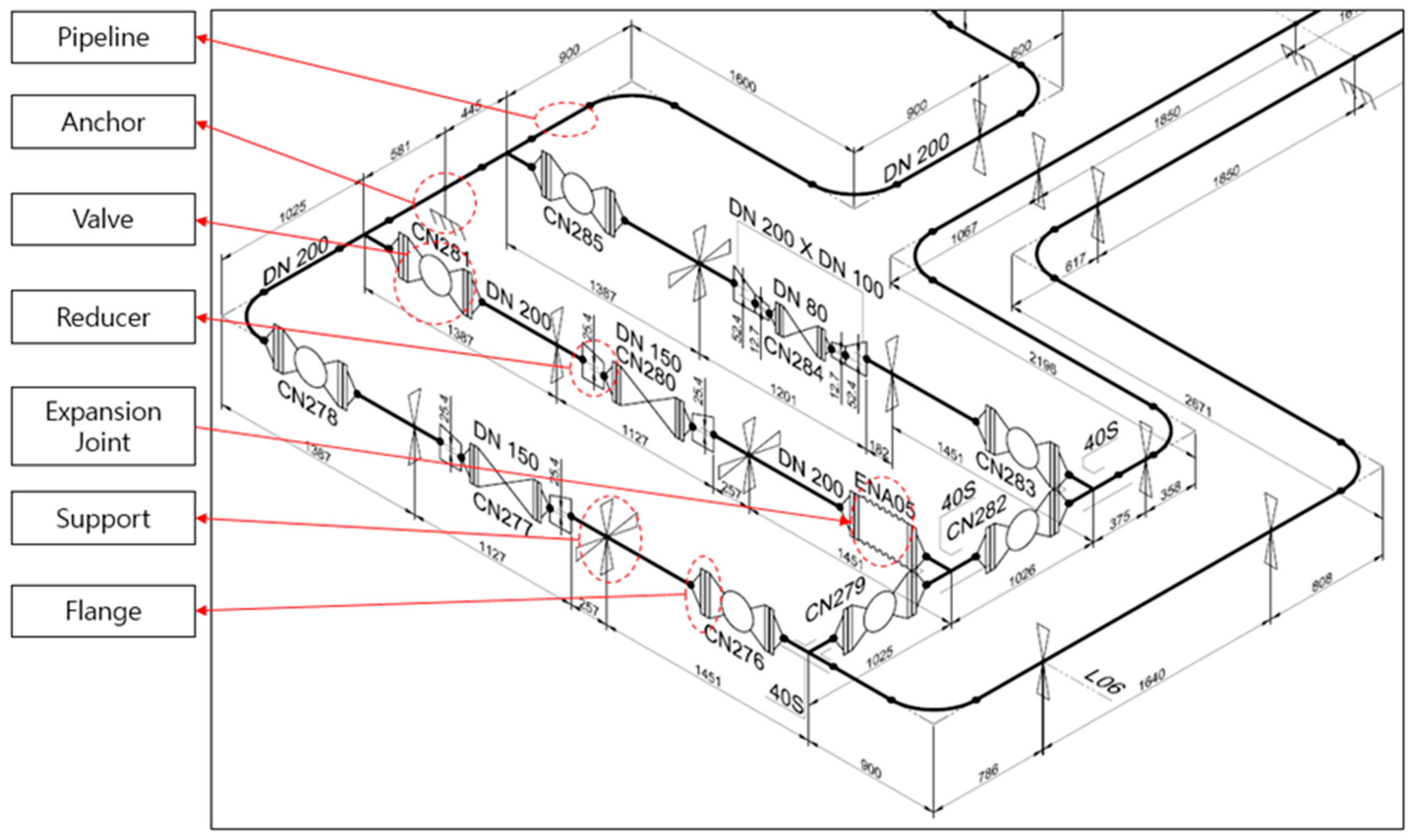
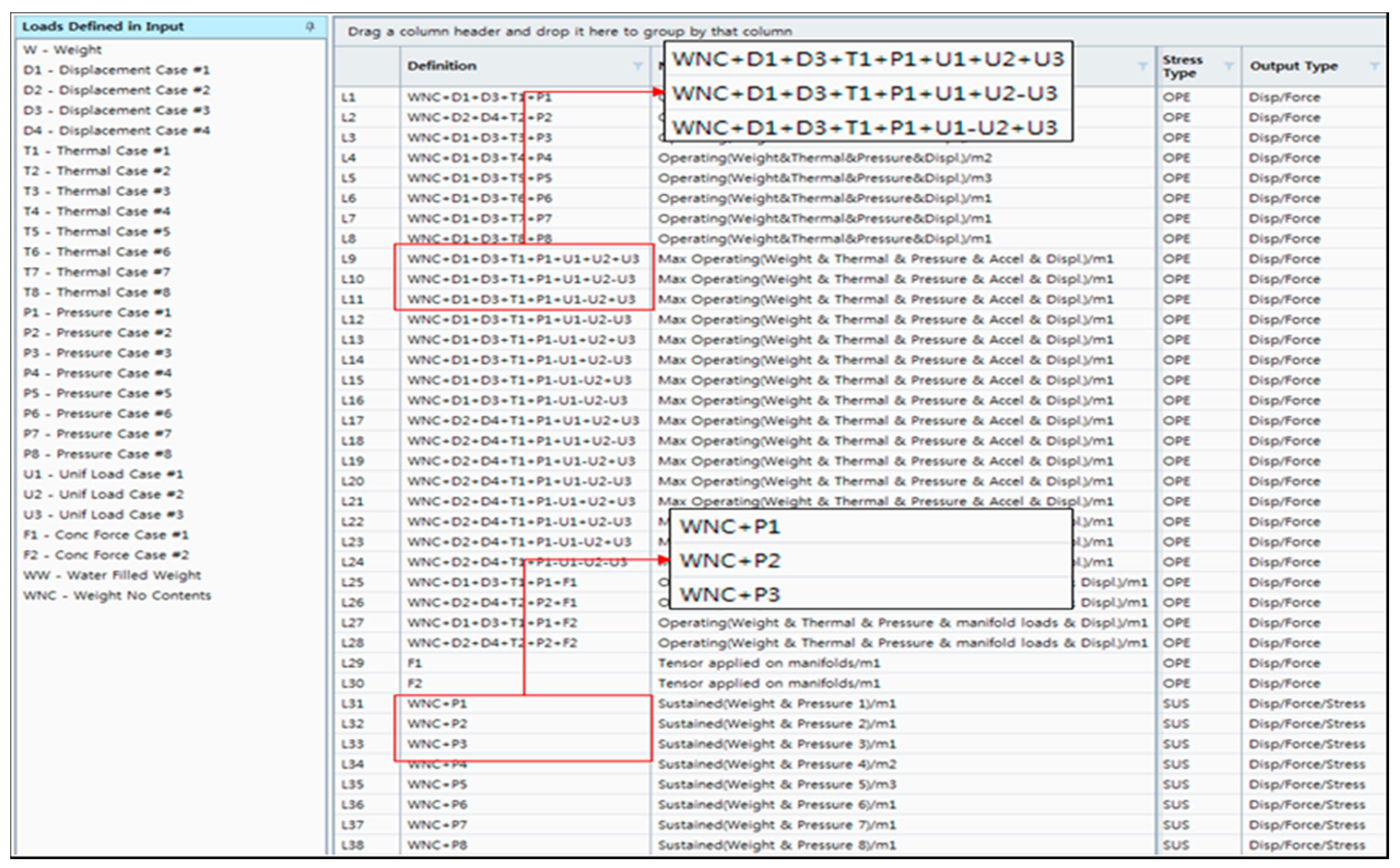
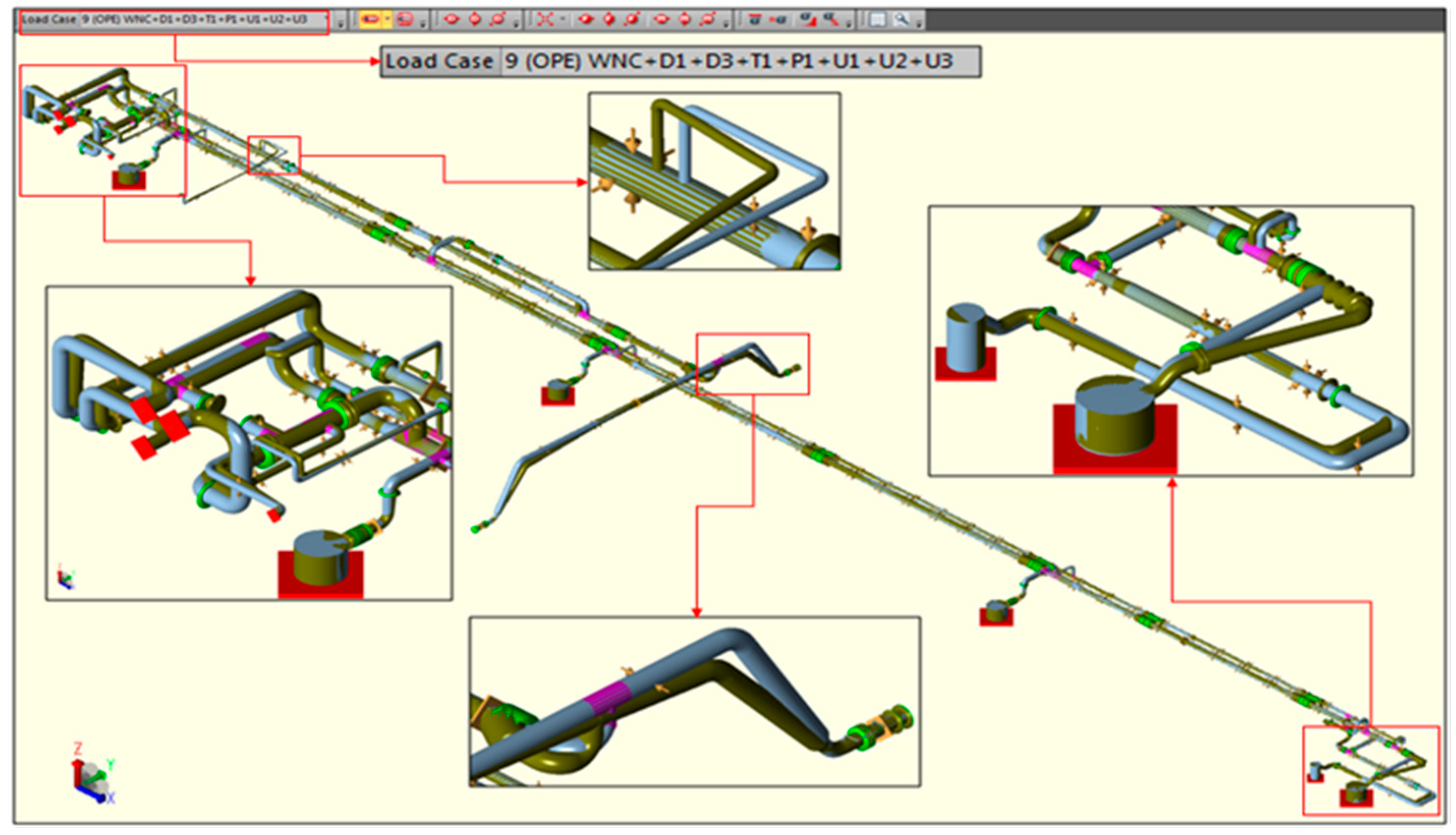
Sustained, occasional, and secondary load conditions suggested by ASME regulations were reflected in a combination of load boundary conditions to analyze the piping stress by reflecting the characteristics of valves, expansion joints and flanges in the LNG carrier piping system. Each load condition and load combination reflected was organized in accordance with ASME Code criteria and reflected each procedure for evaluating stress as follows.
2.3. Loads to be Consider in the LNG Pipe System
After determining the minimum thickness of the pipe, the stress was evaluated according to the ANSI B31.1 code. The maximum stress for each combination of load conditions should be evaluated. If the maximum stress of a load combination does not meet the allowable stress limit, the pipe dimensions or the arrangement of the piping system components should be modified. The piping loads are classified into three types as follows:
Sustained loads acting throughout the operation are the sum of deadweight loads, axial loads caused by internal pressure, and other applied axial loads that are not caused by temperature and accelerations, etc. Deadweight refers to the weight of the pipe and associated components (such as flanges, valves, and strainers mounted on the piping system, the weight of fluid/contents in the piping, and the weight of insulation). Primary stress or sustained stress () is generated by sustained loads. Sustained stress is mainly caused by the pressure of the fluid. It occurs due to the internal and external forces and moments of sustained loads like deadweight, self-weight, and bending moments. The piping codes keep the primary stresses below the yield point by a safety factor, as shown in Equation (2). is the superposition of longitudinal membrane stress () and the weight-bending stress ().
where
and
t are the pressure (MPa) in the pipe, the pipe outer diameter (mm), and the pipe thickness (mm), respectively.
is the equivalent bending moment (N-mm) due to the weight and support load of the insulation, valve, and pump. Z is the section modulus of the pipe and
is the SIF. These comply with ASME B31.1 [
4] Appendix D.
denotes the allowable stress at the maximum operating temperature (values are listed in Appendix A of ASME B31.1 [
4]).
Occasional loads act temporary during the operation and are combined with design pressure and weight. These loads include wind, seismic, breaking waves or green sea impact loads, dynamic loads such as pressure relief, or fluid surge loads. The ASME B31.3 [
3] code has specific requirements for the accumulated hours of the occurrence of such loads. The allowable occasional stress limit is listed in Section 302.3.6 of ASME B31.3 [
3]. Normal operating temperature is used in the assessment of occasional loads. Stresses due to occasional loads are the algebraic summations of longitudinal sustained weight stress, longitudinal pressure stress, and occasional stress. They shall satisfy the stress equation specified in ASME B31.1. [
4]—Equation (3)—which is given below:
where:
where
is the equivalent bending moment due to the sustained load and
is the equivalent bending moment due to the occasional load.
is the factor value determined by the duration time of the occasional load. Equation (3) shows that the longitudinal stress due to occasional loads is less than or equal to
(ASME B31.1 Appendix 102.2.4 [
4]).
is the basic material allowable stress at maximum (hot) temperature.
Thermal expansion and contraction occurs when a pipe heats up and cools down. The piping system must have enough flexibility to handle the thermal expansion and contraction. Secondary loads are driven by the thermal expansion of both the pipes and hull structure, anchors, and restraints, as they are related to the continuity of the piping system. Secondary expansion stress
is generated by the thermal load and forced displacement caused by temperature difference and thermal deformation of the hull and bending (sagging and hogging). In this study, forced displacement load transferred from hull expansion and contraction is added to the thermal expansion loads, along with the consideration of the wave bending moment and the thermal expansion of the deck. The secondary stress (
) should not exceed the allowable stress (
), as shown in Equation (4).
where
and
are the resultant bending stress (MPa) and torsional stress (MPa) caused by thermal load and deformation, respectively. Resultant bending stress (
) is generated by temperature, the deadweight of the pipe, and the weight of insulation, as defined in Equation (5). The torsional stress (
) due to the moment (
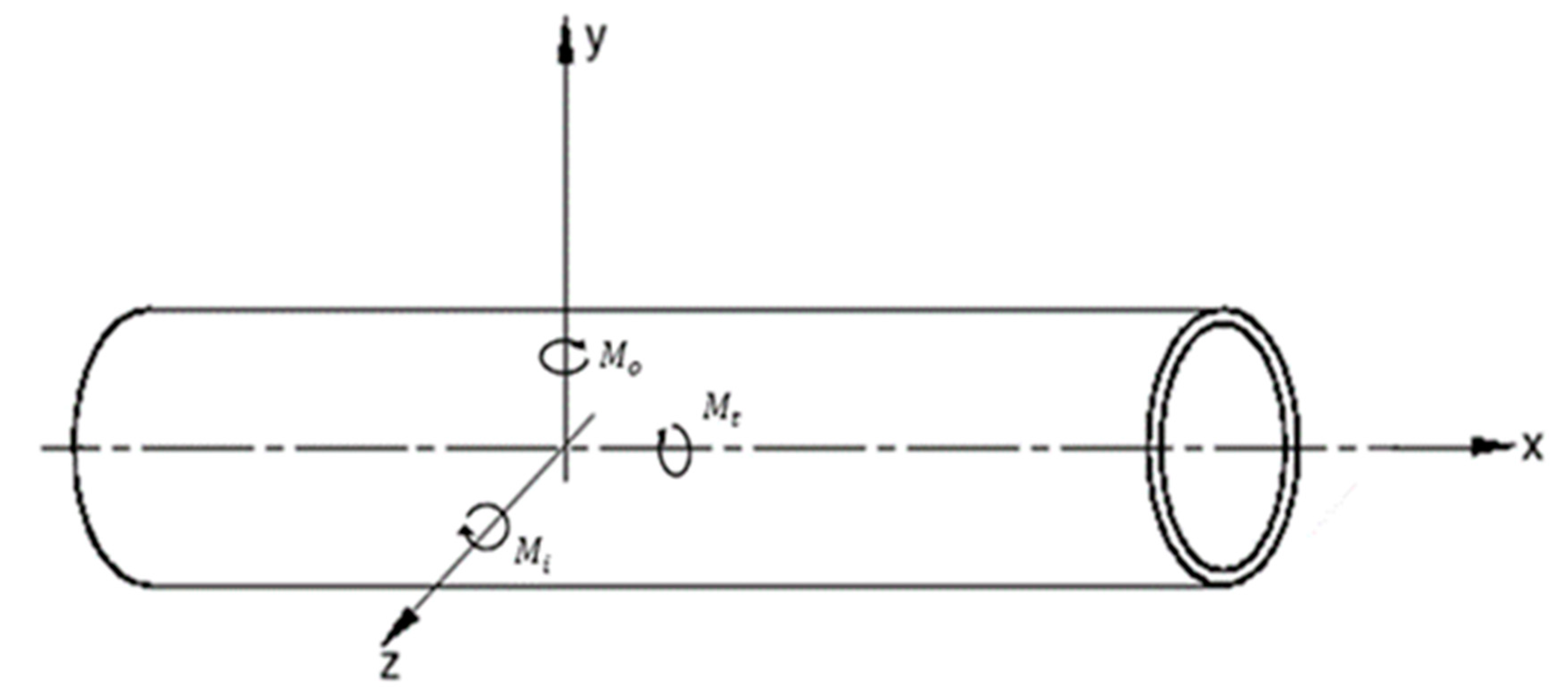
) is given by Equation (6).
where
,
,
are the inner and outer plane bending moments (N-mm), and the torsional moment, as shown in
Figure 1.
,
are the inner and outer plane stress intensification factors, respectively [
19]. The allowable stress (
) is defined by Equation (7).
is calculated with Equation (8) if
is less than or equal to
.
is the stress range factor (accounting for the fatigue load) and is determined by the number of cyclic loads
[
17]. A default value of
= 1.0 is applied here. However, if
is greater than 7000, the value of f specified in Table 1023.2 (C) of ASME B31.1 [
4] is used in Equations (7) and (8).
where:
= Material allowable stress at minimum (cold) temperature expected during the displacement cycle under analysis (MPa) (ASME Table K-1);
= Material allowable stress at maximum metal temperature expected during the displacement cycle under analysis (MPa) (ASME Table K-1);
= Stress range factor.
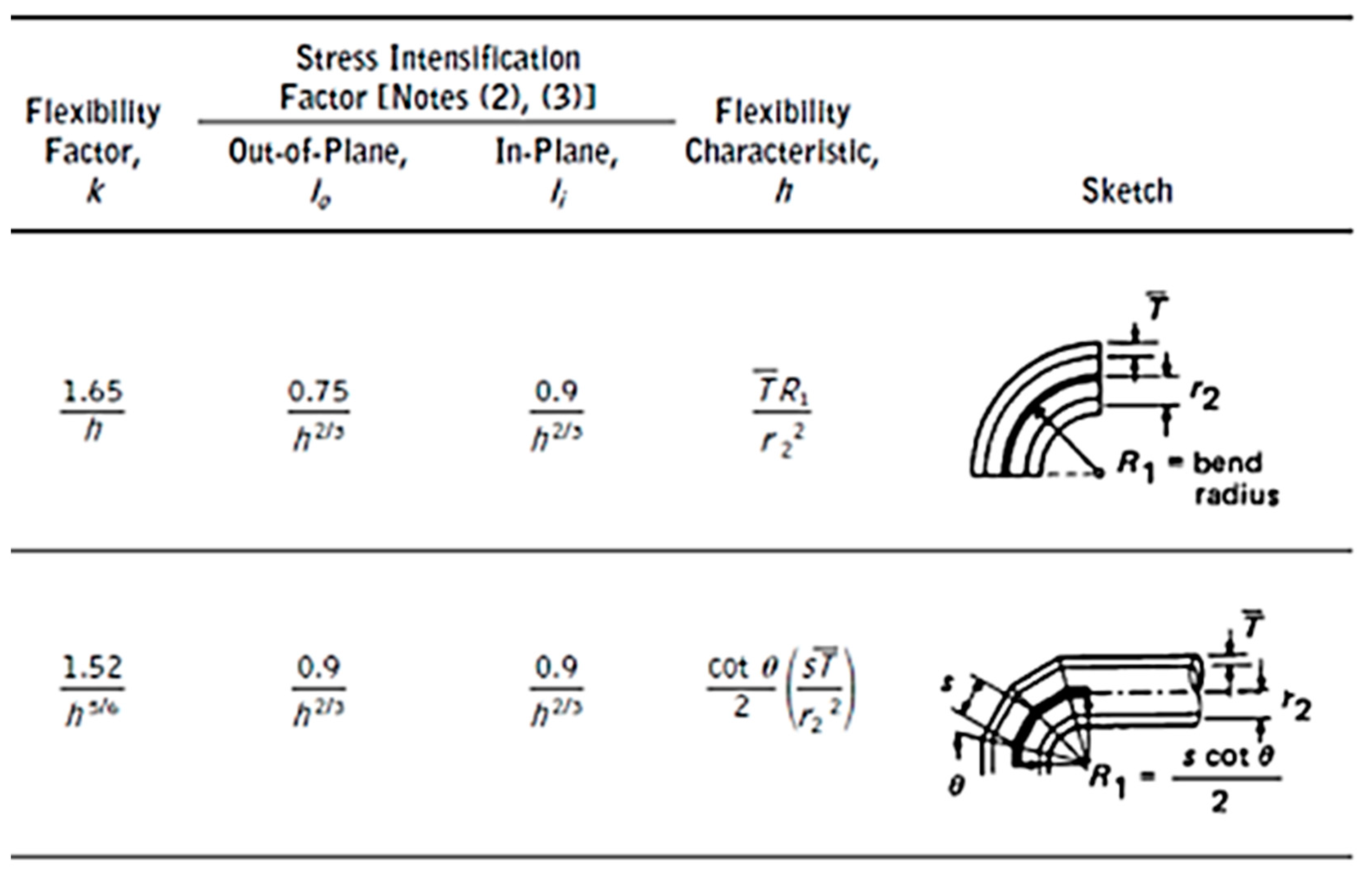
2.4. Stress Intensification Factor (SIF) and Flexibility Factor
The behavior of the straight pipe differs from that of the curved pipe under an externally applied bending moment. The straight pipe acts like a beam while retaining a circular cross section. In contrast, the cross section of the curved pipe becomes oval-shaped (see
Figure 2). SIF is equivalent to the ratio of the maximum bending stress occurring in a straight pipe to that in a curved pipe, subject to bending moment. The bending stress
in a straight pipe is calculated as
. The bending stress in a curved pipe is calculated as
, where
denotes the reduced section modulus of the curved shape. The stresses in the curved pipe are higher compared to a straight pipe of the same size because of the reduced cross section modules. The SIF of the curved pipe is defined by
/
Consider a straight pipe (refer
Figure 1) with length
which will produce rotation
under the action of bending moment
. A bend having same diameter and thickness with same arc length
under the action of same bending moment
will exhibit
rotation.
is called the flexibility factor.
Figure 2 shows examples of SIFs and flexibility factors.
2.5. Bending Moment Generated by Thermal Expansion
The deadweight, thermal expansion, and forced displacement of the pipe are converted to the equivalent bending moment and the equivalent axial force to assign the load boundary condition on the pipe elements. This section summarizes both the equivalent bending moment and the equivalent axial force due to thermal expansion/contraction. The strain ε of the beam can be expressed as the sum of the elastic strain
and the thermal strain
, as shown in Equation (9). In addition, because the strain of a pipe can be divided into an axial strain (
) and a bending strain (
), the in-plane and out-of-plane deformation ratios of the beam can be expressed by Equation (10). From Equations (9) and (10), the stress–strain relation of the beam can be obtained, as shown in Equation (11).
where
,
, and
are the thermal expansion coefficient, temperature distribution, and curvature of beam, respectively. Integrating Equation (11) with respect to the cross section of the beam yields Equation (12). Consequently, the axial strain (
) and the equivalent axial load (
) at the central axis due to thermal expansion can be defined by Equation (13). Integrating Equation (11) yields Equation (14); the equivalent bending moment (
) can be obtained as shown in Equation (15).


