Abstract
Vertical axis wind turbine (VAWT) is a competitive power generation device due to structural simplicity, wind direction independence, no yaw mechanism required, easier maintenance, and lower noise emission. However, blade tip vortex will be generated at both ends of the blade during the rotation, resulting in torque loss and efficiency reduction. In this paper, computational fluid dynamics is used to study blade tip vortex and its reduction technique of a single-blade VAWT rotor in real scale. By monitoring the force and flow field at different heights of the blade, the influence ranges of tip vortex are obtained. The reduction effect of the bulkhead obtained from the blade profile curve is studied, and the size of the bulkhead is optimized. On the basis of adding the optimal bulkhead, the influence of the supporting strut is also explored. The joint action is obtained by changing the location of the supporting strut. The results show that the top supporting strut-bulkhead structure is the optimal position. The power-extraction efficiency of the rotor with this integrated structure is significantly improved at optimal tip speed ratios (TSRs) and higher TSRs.
1. Introduction
Wind power is one of the solutions to energy problem as a clean energy source with large reserves in nature. According to the Renewables 2019 Global Status Report [1], in the whole year of 2018, the installed capacity of wind power in the world exceeded 51 gigawatt (GW), with a growth rate of 9%, and the total capacity reached to 591 GW. At present, the traditional horizontal axis wind turbine (HAWT) is more popular in the wind energy market due to its advanced development and high efficiency [2]. However, HAWT has difficultly achieving larger sizes because of the limitation of blade length and strength. On the other hand, vertical axis wind turbine (VAWT) has attracted more and more researchers’ and manufacturers’ attention due to its advantages of adaptiveness to wind direction, convenient installation and maintenance, and the ability to be expanded to larger sizes [3,4].
Improving the efficiency of VAWT is an important target in wind energy generation. Tip vortex is part of the three-dimensional unsteady flow, which constantly sheds in each blade revolution, decreasing the torque and causing structural vibrations. Kudela and Malecha revealed that the detachment of the vortex from the boundary layer leads to the sudden drop of the lift force, based on a vortex-in-cell model [5]. Hofemann and Simao et al. [6,7] experimentally detailed and qualified the evolution of the tip vortex in the near wake with 3D-Stereo Particle Image Velocimetry. Hamada et al. [8], Howell et al. [9], and Lam and Peng [10] compared the torque generated by blade between 2D and 3D computational fluid dynamics(CFD) models, and obtained the conclusion that the 3D effects significantly reduced the extraction rate of wind power. Yanzhao Y et al. [11] studied the effects of tip vortex on the wake of a two-blade VAWT with different tip speed ratios (TSRs) by CFD simulations. Balduzzi et al. [12] conducted a detailed 3D CFD analysis of H-type Darrieus single-blade rotor with an aspect ratio (AR) of 17.5. Studies have shown that the torque loss caused by the three-dimensional effect due to the finite blade length is equivalent to the blade length loss of 1.5c. Many researchers have made efforts to reduce the tip loss. Zanforlin and Deluca [13] proposed that should be considered in design to avoid the effect of tip vortex. Some others have proposed ways to change the blade shape for tip vortex reduction, such as a helical blade [14,15] and elliptical blade tip [16,17].The installation of a tip device is also a method to improve the turbine performance. Winglets and bulkheads are mostly used in experiments and simulations [16,17,18,19]. Considering the 3D effect caused by supporting strut, some research was undertaken in terms of the cross section and location of the strut [8,16,20,21,22]. The results show that the more streamlined hydrodynamic strut section provides lower strut drag.
To date, most of the 3D effect studies of VAWT focus on the medium or small turbines. In this paper, the 3D effects of blade tip vortex and supporting strut are studied by CFD numerical simulation with a large turbine model in real scale. The objectives of this study are to explore the methods of reducing tip vortex and optimizing the structure of the turbine, which could improve the performance of the VAWT.
The paper is organized as follows. Section 2 introduces the numerical methodology and some parameter settings. The independence verification of grid and time-step is also presented. Section 3 shows the numerical results and analysis. Section 3.1 analyzes the effect ranges of tip vortex in detail. In Section 3.2, a bulkhead is added to reduce tip vortex, and the size of the bulkhead is optimized. Section 3.3 considers the influence of supporting strut. Additionally, the optimal position and structural form of supporting strut are found based on the addition of the optimal bulkhead. Section 3.4 compares the gains on the presented structure with different TSRs.
2. Numerical Methodology
2.1. Computational Model
The subject of our study is a three-blade VAWT rotor whose rated power is 2.5MW. The rotor is part of an offshore floating twin VAWT system, as shown in Figure 1. The ratio of the height and the diameter for each rotor is larger than the conventional single-rotor VAWT. The main parameters and the model diagram of the rotor are shown in Table 1 and Figure 2, respectively. The large chord length of 7.2 m was chosen by directly scaling, based on our model-scale experimental results [23]. It is worth noting that this chord length may not be the optimal one for this rated power output due to the scale effects. In addition, a shorter blade chord will lighten the weight of the rotor, reduce the solidity of the rotor, and tend to enhance the power coefficient. Finding the optimal chord length, one may need to conduct a detailed investigation. Focusing on the objective of this work, the blade with the chord length of 7.2m was chosen to be the study subject. Considering the computational resources in real scale simulation, this paper simplified the model and only studied the single rotor with a single blade.
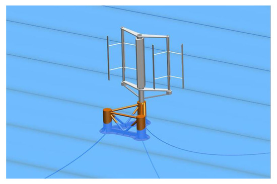
Figure 1.
Concept design of an offshore floating twin vertical-axis wind turbine system.

Table 1.
Main parameters of the rotor.
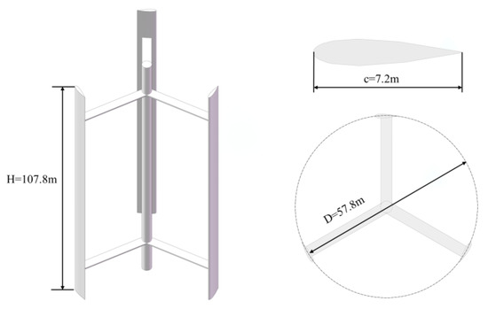
Figure 2.
Model diagram of the rotor.
In the numerical calculation, we used the finite-volume Navier–Stokes solver in the STAR-CCM+ for simulation. In order to improve the accuracy and minimize the calculation cost, this study only carried out a semi-basin calculation, and divided the computational domain into external flow field and internal flow field, as shown in Figure 3. The internal flow field was a cylindrical region, including the rotor part of the VAWT, which rotated. The external flow field was a rectangular region, including the part outside the rotor. The center of the column in midspan was selected as the coordinate origin of the computational domain. The velocity inlet was located at the 3D position in the upstream area from the rotor center, and the pressure outlet was located at the 10D position in the downstream area. The domain of the entire flow field was 13D long, 8D wide, and 1.5H high. The cylinder diameter and the height of the rotor domain were 1.18D and 0.8H. These two computational domains were connected by interfaces.
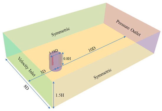
Figure 3.
Computational domain with boundary conditions and sizes.
The surface of blade was set as wall, and the remaining boundaries of the domain were set as symmetrical plane. The turbulence model was SST , commonly used in the numerical simulation of VAWT [11,13,21,24,25,26]. The wind speed at the velocity inlet was set at 10m/s, and the pressure at the outlet was set at 0 Pa. The blade tip speed ratio (TSR) was set at 3, so the rotation angular velocity of the rotor was 1.038rad/s.
The grid form adopted in this study was the cut volume grid. Two layers of wake refinement area were set in the outflow field whose basic size of the grid was 0.8 chord length. The grid size was 50% of the basic size in the first layer and 25% in the second layer. In order to get a better transition between the external flow field and the internal one, the basic size of the rotating domain was the same as the size in the second layer of refinement area. The condition of the blade was defined as no-slip, and 20 layers of prismatic boundary layer cells were generated with growth ratio of 1.2. Local refinement was carried out on the blade surface. The total number of grids was 5,694,103. The computational mesh of the whole domain and near the blade are shown in Figure 4. Using implicit unsteady method, a time step was set at 0.0168s, namely the time for the rotor turning 1 °.
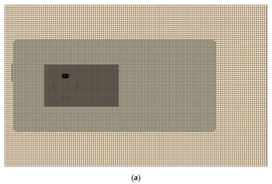
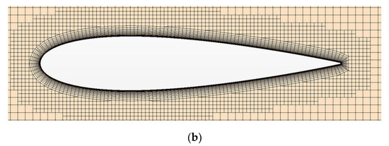
Figure 4.
(a) Computational mesh of the domain; (b) computational mesh near the blade surface.
2.2. Mesh Convergence
Another two sets of mesh with coarser division and finer division were obtained by changing the basic size. The three mesh sets are shown in Table 2. The instantaneous torque coefficient is defined by Equation (1), where due to the semi-basin simulation. The blade instantaneous torque curves of the three mesh sets are shown in Figure 5. According to Equation (2), we could obtain the work done by torque using the area under the curve. The deviation of the work done obtained by medium mesh and fine mesh was 2%, much less than the deviation of medium and coarse mesh. Moreover, the torque curves of medium and fine mesh showed more similar variation. Thus, the medium mesh was considered to be converged and such set was used for subsequent simulations.
Table 2.
Mesh size and quantity.
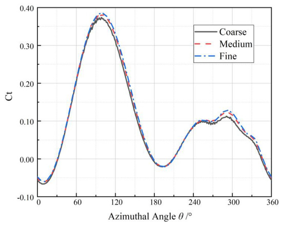
Figure 5.
Instantaneous torque of a blade under three mesh sets.
2.3. Time-Step Convergence
Balduzzi et al. [27] noted that in most studies of the VAWT simulation, the time-step is set to the time in which the rotor makes a rotation between 0.5° and 2°. Three groups of time-step were used to calculate, respectively, the rotor turning 1°, 2°, and 3°. For the 1°and 2° time settings, the difference of the torque area under the curves (Figure 6) were less than 1‰, so the 2° turning for a time-step converged.
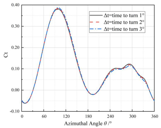
Figure 6.
Instantaneous torque of a blade under three time-step sets.
2.4. Numerical Model Validation against Model-Scale Experimental Data
Before further investigating the numerical simulation results, it is necessary to check the reliability of abovementioned modelling techniques against experimental data. However, there is no experimental data available for full-scale 2.5MW VAWT. The model-scale experimental measurements were adopted to validate our numerical model. More information on the wind tunnel experiments can be found in the previous publication [23]. Y+ distribution and mesh generation along the blade of the numerical model is shown in Figure 7. The average of the measured torque acting on the wind turbine rotor under the wind speed of 7.7 m/s are plotted in Figure 8, together with the predictions of CFD simulations based on the abovementioned modelling techniques. It can be seen that the torque predicted by numerical simulation tends to be slightly larger than the experimental value at low rotational speeds and slightly smaller at higher rotational speeds. Overall, the simulated torque curve agrees well with the one obtained from the experiment, and is therefore considered valid.
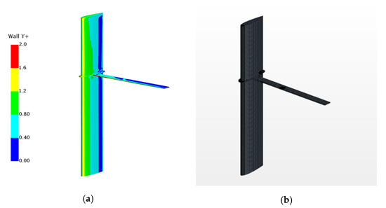
Figure 7.
(a) Y+ distribution along the blade; (b) numerical mesh on the blade.
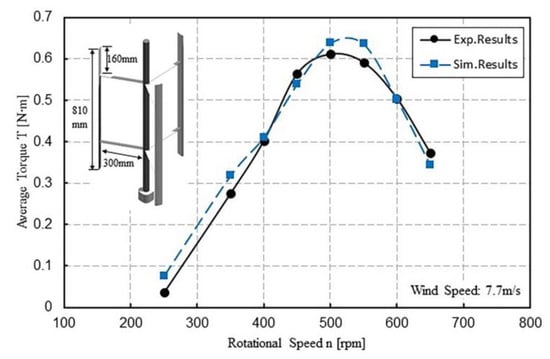
Figure 8.
Experimentally obtained and numerically simulated torque as a function of rotational speed of an isolated vertical axis wind turbine (VAWT).
3. Results and Numerical Analysis
3.1. Influence of Tip Vortex
In order to better calculate and monitor the influence range of tip vortex on the blade surface, the blade length was divided based on the chord length. Airfoil sections with a height of 0.05m were intercepted at positions 0.05c, 0.25c, 0.5c, 1c, 2c, 3c, 4c, 5c, 6c, and 7c from the tip of the blade. As shown in Figure 9, the initial position angle of blade is 0°. From 0° to 180° is upwind region in a rotating cycle (upstream), and 180° to 360° is downwind region (downstream).
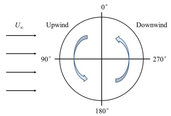
Figure 9.
Upwind and downwind paths during a rotation.
The instantaneous torque curves of the fourth cycle were selected for analysis, as shown in Figure 10. The ordinate is the instantaneous torque coefficient per 0.05m height section, which is defined by Equation (3). Here, denotes the instantaneous torque per unit section. It can be seen that the torque at section 0.05c is negative for most of the cycle. In the upwind region, the closer the section is to the blade tip, the smaller the torque contribution will be. The sections below 3c from the tip of the blade are slightly affected by tip vortex. In the downwind area between 300° and 340°, the torque curve shows a steep fall. It can be observed from the three-dimensional vortex diagram that this steep drop is caused by the collision between the blade and the vortex shedding in the previous cycle, as shown in Figure 11.
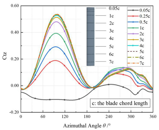
Figure 10.
Instantaneous torque of sections at different heights during a rotation.
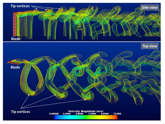
Figure 11.
Collision between the blade and the vortex in the downwind.
These instantaneous torque curves can be divided into two modes according to the downwind variations at different heights. The distances of 0.05c, 0.25c, and 0.5c from the blade tip are in the first mode, and distances of 1c to 7c from the blade tip are in the second mode. In the first mode, the torque is greatly reduced due to severe influence of tip vortex and severe damage of flow field. Additionally, the closer the section is to the blade tip, the greater the torque reduction will be. It can be said that for height above the 0.5c-section, tip vortices are more likely to disturb the flow field, as shown in Figure 12. However, in the second mode, there is a larger torque of section closer to the blade tip in a specific azimuthal angle range, which could be explained as follows. The geometrical relationship between angle of attack and blade azimuthal angle is shown in Figure 13, and the lift coefficient (angle of attack of NACA0018) is shown in Figure 14. The data is obtained by applying the Xfoil software, and published on the website, http://airfoiltools.com/polar/details?polar=xf-naca0018-il-1000000. To make sure the predicted install angle is adequately accurate, we also conducted our 2D numerical simulations to predict the lift coefficient corresponding to several angles of attack of NACA0018 airfoil. The predicted results are compared with the published data in Figure 14. The predicted lift coefficient is slightly lower, but trends of two results are close, and both results show that the stall angle of NACA0018 at high Reynolds number is around 17°. From Figure 13, we can obtain the geometrical relationship between angle of attack and azimuthal angle, as shown in Equation (4). For simplicity, the induction factor was ignored [28]. It can be derived that (224.3°, 281.7°) in the downwind is a zone for the blade stall by Equation (4). At a height close to the tip of the blade, due to the existence of tip vortex, a downwash angle is generated [12], which reduces the attack angle of the blade and fails to reach the critical angle of stall. Thus, in the range of 220° to 280° shown in Figure 10, the higher the height from 1 c to 7 c, the greater the torque value will be.
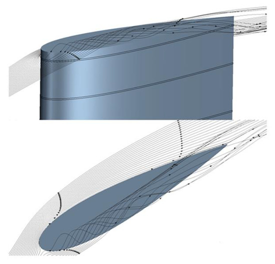
Figure 12.
Streamline at the blade tip.
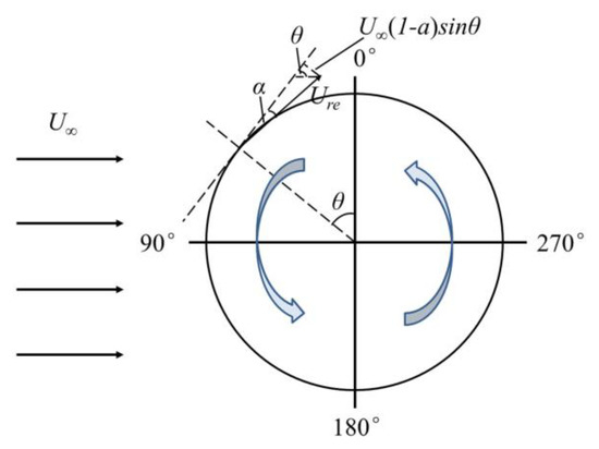
Figure 13.
Geometrical relationship between angle of attack and blade azimuth. is the azimuthal angle, is the angle of attack, is the axial induction factor.
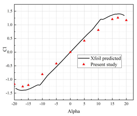
Figure 14.
NACA0018 airfoil lift coefficient (angle of attack).
3.2. Bulkhead Inhibition of Tip Vortex
In order to restrain the influence of tip vortex on blade surface, a tip device was added. The bulkhead was obtained by expanding the blade profile curve. The edge of the bulkhead was 2m away from the blade surface, and the thickness was 0.2m. The edge was set as a round angle with a radius of 0.1m. Figure 15 shows the streamline at different heights of the blade sections when the bulkhead is added or not. The azimuthal angle is 88°.It can be seen from Figure 15a that the closer the height is to the top of the blade, the more disordered the streamline is. Figure 15b shows the streamline is smoother under the action of the bulkhead. The comparison of instantaneous torque at different heights is shown in Figure 16. It can be seen that the instantaneous torque of the blade with a bulkhead is much larger than that of the blade without a bulkhead above the height of the 1c-section. That is, the inhibition of the bulkhead on tip vortex is obvious above the height of 1c-section, and there is basically no effect below the height of 3c-section.
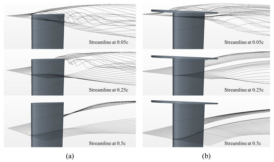
Figure 15.
The streamline at different heights of the blade sections when the azimuthal angle is 88°: (a) without a bulkhead; (b) with a bulkhead.

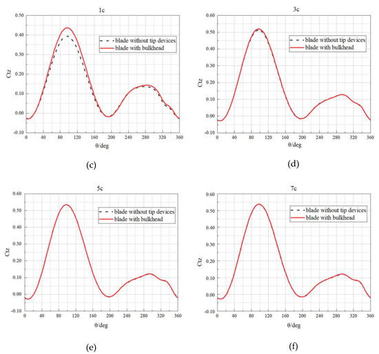
Figure 16.
Instantaneous torque with or without a bulkhead at height of (a) 0.25c; (b) 0.5c; (c) 1c; (d) 3c; (e) 5c; (f) 7c.
In order to study the effect of bulkhead size on turbine performance, six cases ( = 0, 0.18c, 0.35c, 0.56c, 0.76c, and 1c) were selected for calculation, where represents the distance between the edge of the bulkhead and the blade surface. The geometric models are shown in Figure 17.

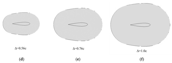
Figure 17.
Perspective view of six bulkhead sizes: (a) = 0; (b) = 0.18c; (c) = 0.35c; (d) = 0.56c; (e) = 0.76c; (f) = 1.0c.
In the simulation, the total torque, torque of the blade, and torque of the bulkhead were monitored, respectively. Work done by the blade with six sizes of bulkhead were calculated from the torque data and are shown in Figure 18. We used a non-dimensional quantity to represent the work . The total work concludes both the bulkhead and the blade work. It can be seen from Figure 18 that, as the size of the bulkhead increases, the blade work shows an increasing trend. However, the larger the bulkhead size is, the greater the resistance will be. The growth trend of the total work starts to slow down after the corresponding point of = 0.35c, and = 0.35c is considered as the preferred size. At this time, the total work increases by 4.25% compared with the blade without a bulkhead.
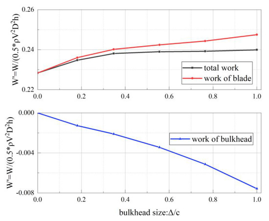
Figure 18.
Total work, blade work, and bulkhead work under six sizes of bulkhead.
3.3. Influence of Supporting Strut
The supporting strut connecting the blade to the central column also produces a three-dimensional effect that affects the performance of the rotor. The cross section of supporting strut usually has several forms, such as rectangle, circle, and airfoil. In this part, a streamlined airfoil section was selected for the modeling and calculation.
The NACA0018 airfoil, the same as the blade, was selected for the supporting strut, and the chord length was 0.5c, as shown in Figure 19.
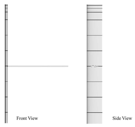
Figure 19.
Blade-supporting strut rotor model.
On the basis of installing a bulkhead with size = 0.35c, four cases where the supporting strut was located at 4c, 2.5c, and 1c from the blade tip and at the top were selected for calculation, as shown in Figure 20.
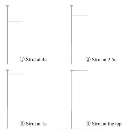
Figure 20.
Supporting strut at different heights.
Table 3 lists the total work and the work of blade in each case, also presented by . When the supporting strut is 4c, 2.5c, and 1c away from the blade tip, it performs negative work. Therefore, the total work is less than the work generated by the blade. However, in the process of the supporting strut moving up, the difference between the total work and the work of blade becomes smaller and smaller, which indicates that the resistance of the supporting strut together with the bulkhead gradually decreases. When the strut is at the top, the total work is even greater than that of the blade part. As can be seen from Figure 21, a forward torque is generated when the strut is at the top. Such results can be attributed to the windward angle of attack generated by the incoming flow when the strut is at the top of the turbine, thus generating lift.
Table 3.
Total work and work of the blade with a strut at different heights.
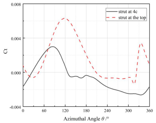
Figure 21.
Instantaneous torque of the supporting strut at the top and at the height of 4c.
As can be seen from Figure 22, when the supporting strut is at the top, the torque value of the 0.05c-section to 0.5c-section increases compared with that when only the optimal bulkhead is installed. That is, the supporting strut enhances the effect of tip vortex reduction. From Figure 23, it can be seen that the streamline is smoother when the supporting strut is at the top. We call this structure the top supporting strut-bulkhead structure. Therefore, the supporting strut at the top has two advantages: firstly, it generates forward torque rather than resistance; secondly, it enhances the effect of reducing tip vortex. As can be seen from Table 3, the top supporting strut-bulkhead structure has a work performance gain of 9.05%.

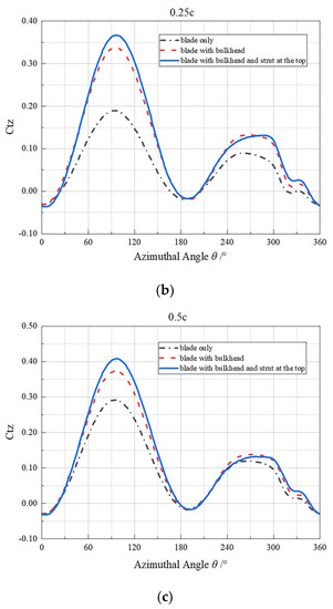
Figure 22.
Comparison of instantaneous torque among three different blade tip shapes at height of (a) 0.05c; (b) 0.25c; (c) 0.5c.
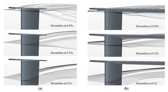
Figure 23.
The streamline at different heights of the blade sections when the azimuthal angle is 88°: (a) with a bulkhead; (b) with a top supporting strut-bulkhead structure.
3.4. Performance of the Top Supporting Strut-Bulkhead Structure under Different TSRs
In the previous study, only the calculation and analysis at TSR = 3 were carried out. Since the aerodynamic performance varies under different TSRs [29], other cases were calculated under TSR = 1, 2, and 4. Figure 24 shows the work done by the whole structure under four TSRs. TSR = 1 and 2 are low tip speed ratios, while TSR = 3 and 4 are good and high ones. When TSR is low, blade stall is serious and the top supporting strut-bulkhead structure does not perform well. However, under higher TSRs, it can be seen that the work done by the top supporting strut-bulkhead structure is much larger. When TSR = 3 and TSR = 4, compared with conventional blade-and-strut structure, the work done by the proposed structure is increased by 9.05% and 10.48%, respectively.
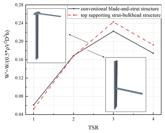
Figure 24.
Work done by torque of the whole structure under four TSRs.
4. Discussion
In this paper, a numerical model for predicting the aerodynamic performance of a real-scale VAWT was established. The influence of blade tip vortex was analyzed, and the supporting strut at different heights was considered together with the action of the bulkhead. The structure of the rotor was optimized with the selected bulkhead size and strut position, which greatly improved the performance of the rotor.
First, the torque and flow field at different heights of the blade were monitored to analyze the influence ranges of tip vortex. In the upwind area of rotation, tip flow was mainly manifested as the destruction of flow field. The torque of the blade section less than 3c away from the tip of the blade decreased to different degrees, and the closer it was to the tip, the more obvious the reduction was. The overall torque of the blade section at a height less than 0.05c away from the blade tip was negative work.
Second, a bulkhead was added to reduce blade tip vortex. The effect was more obvious when the bulkhead was enlarged. However, a larger bulkhead could generate resistance, which limited the improvement of the total torque. When the bulkhead size increased to a certain extent, the total torque of the blade changed slowly. In the six cases of = 0, 0.18c, 0.35c, 0.56c, and 0.76c selected in this study, it was calculated that = 0.35c was the best extension size, and the torque power of the blade at this time increased by 4.25% compared with the blade without a tip device.
In addition, different heights of the supporting strut were considered in the calculation. When the position of the strut moved from the 4c-section to 1c-section, the total power of the rotor kept increasing. The supporting strut could reduce tip vortex when it was located at the blade tip together with the bulkhead. At this time, the total power increased by 9.05% compared with the conventional structure whose supporting strut was at the height of 4c-section and no bulkhead.
Moreover, the effect of the top supporting strut-bulkhead structure was compared under different tip speed ratios. At low TSRs, because of the serious stall, the supporting strut-bulkhead structure did not show performance gain. While at higher TSRs, the torque of the whole structure was significantly improved.
The design of this supporting strut-bulkhead structure provides an option for the design and optimization of large VAWT structures in the future. Further studies can consider the interaction between several blades and whether multi-blades will limit the installation of tip devices.
Author Contributions
Conceptualization, Y.J. and C.H.; Data curation, C.H.; Formal analysis, C.H.; Investigation, Y.J. and C.H.; Methodology, C.H. and P.Z.; Project administration, Y.J.; Resources, T.S.; Software, T.S.; Supervision, Y.J.; Validation, P.Z.; Visualization, C.H.; Writing—original draft, C.H.; Writing—review and editing, Y.J. and T.S. All authors have read and agreed to the published version of the manuscript.
Funding
Qingdao National Laboratory for Marine Science and Technology (QNLM2016ORP0402); National Natural Science Foundation of China (Grant No. 51639003, 51279030); and the Fundamental Research Funds for the Central Universities (DUT2017TB05).
Acknowledgments
The authors would like to thank Qingdao National Laboratory for Marine Science and Technology, National Natural Science Foundation, and the Fundamental Research Funds for the Central Universities.
Conflicts of Interest
The authors declare no conflict of interest.
References
- REN21. Renewables 2019: Global Status Report. Available online: http://www.ren21.net/gsr-2019/ (accessed on 26 July 2019).
- Möllerström, E.; Gipe, P.; Beurskens, J.; Ottermo, F. A historical review of vertical axis wind turbines rated 100 kW and above. Renew. Sustain. Energy Rev. 2019, 105, 1–13. [Google Scholar] [CrossRef]
- Liu, J.; Lin, H.; Zhang, J. Review on the technical perspectives and commercial viability of vertical axis wind turbines. Ocean. Eng. 2019, 182, 608–626. [Google Scholar] [CrossRef]
- Mohamad, A.; Mohd Amin, N.A.; Toh, H.T.; Abdul Majid, M.S.; Daud, R. Review of Analysis on Vertical and Horizontal Axis Wind Turbines. Appl. Mech. Mater. 2014, 695, 801–805. [Google Scholar] [CrossRef]
- Kudela, H.; Malecha, Z.M. Eruption of a boundary layer induced by a 2D vortex patch. Fluid Dyn. Res. 2009, 41, 055502. [Google Scholar] [CrossRef]
- Hofemann, C.; Ferreira, C.; van Bussel, G.; Kuik, G.; Scarano, F.; Dixon, K.R. 3D stereo PIV study of tip vortex evolution on a VAWT. In Proceedings of the European Wind Energy Conference and Exhibition EWEC, Brussels, Belgium, 31 March–3 April 2008; pp. 1–8. [Google Scholar]
- Simao Ferreira, C.; Dixon, K.; Hofemann, C.; van Kuik, G.; van Bussel, G. VAWT in Skew: Stereo-PIV and Vortex Modeling. In Proceedings of the 47th AIAA Aerospace Sciences Meeting Including The New Horizons Forum and Aerospace Exposition, Orlando, FL, USA, 5–8 January 2009. [Google Scholar]
- Hamada, K.; Smith, T.; Durrani, N.; Qin, N.; Howell, R. Unsteady Flow Simulation and Dynamic Stall Around Vertical Axis Wind Turbine Blades. In Proceedings of the 46th AIAA Aerospace Sciences Meeting and Exhibit, Reno, NV, USA, 7–10 January 2008. [Google Scholar]
- Howell, R.; Qin, N.; Edwards, J.; Durrani, N. Wind Tunnel and Numerical Study of a Small Vertical Axis Wind Turbine. Renew. Energy 2010, 35, 412–422. [Google Scholar] [CrossRef]
- Lam, H.F.; Peng, H.Y. Study of wake characteristics of a vertical axis wind turbine by two- and three-dimensional computational fluid dynamics simulations. Renew. Energy 2016, 90, 386–398. [Google Scholar] [CrossRef]
- Yang, Y.; Guo, Z.; Zhang, Y.; Jinyama, H.; Li, Q. Numerical Investigation of the Tip Vortex of a Straight-Bladed Vertical Axis Wind Turbine with Double-Blades. Energies 2017, 10, 1721. [Google Scholar] [CrossRef]
- Balduzzi, F.; Drofelnik, J.; Bianchini, A.; Ferrara, G.; Ferrari, L.; Campobasso, M.S. Darrieus wind turbine blade unsteady aerodynamics: A three-dimensional Navier-Stokes CFD assessment. Energy 2017, 128, 550–563. [Google Scholar] [CrossRef]
- Zanforlin, S.; Deluca, S. Effects of the Reynolds number and the tip losses on the optimal aspect ratio of straight-bladed Vertical Axis Wind Turbines. Energy 2018, 148, 179–195. [Google Scholar] [CrossRef]
- Alaimo, A.; Esposito, A.; Messineo, A.; Orlando, C.; Tumino, D. 3D CFD Analysis of a Vertical Axis Wind Turbine. Energies 2015, 8, 3013–3033. [Google Scholar] [CrossRef]
- Cheng, Q.; Liu, X.; Ji, H.S.; Kim, K.C.; Yang, B. Aerodynamic Analysis of a Helical Vertical Axis Wind Turbine. Energies 2017, 10, 575. [Google Scholar] [CrossRef]
- Islam, M.; Fartaj, A.; Carriveau, R. Analysis of the design parameters related to a fixed-pitch straight-bladed vertical axis wind turbine. Wind Eng. 2008, 32, 491–507. [Google Scholar] [CrossRef]
- Amato, F.; Bedon, G.; Raciti Castelli, M.; Benini, E. Numerical Analysis of the Influence of Tip Devices on the Power Coefficient of a VAWT. Proc. World Acad. Sci. Eng. Technol. 2013, 7, 1035–1060. [Google Scholar]
- Mishra, N.; Gupta, A.S.; Dawar, J.; Kumar, A.; Mitra, S. Numerical and Experimental Study on Performance Enhancement of Darrieus Vertical Axis Wind Turbine with Wingtip Devices. J. Energy Resour. Technol. 2018, 140, 121201. [Google Scholar] [CrossRef]
- Laín, S.; Taborda, M.; López, O. Numerical Study of the Effect of Winglets on the Performance of a Straight Blade Darrieus Water Turbine. Energies 2018, 11, 297. [Google Scholar] [CrossRef]
- Islam, M.; Amin, M.; Ting, D.; Fartaj, A. A New Airfoil for the Supporting Struts of Smaller-Capacity Straight-Bladed VAWT. In Proceedings of the 12th AIAA/ISSMO Multidisciplinary Analysis and Optimization Conference, Victoria, BC, Canada, 10–12 September 2008; p. 5874. [Google Scholar] [CrossRef]
- Marsh, P.; Ranmuthugala, D.; Penesis, I.; Thomas, G. Three-dimensional numerical simulations of straight-bladed vertical axis tidal turbines investigating power output, torque ripple and mounting forces. Renew. Energy 2015, 83, 67–77. [Google Scholar] [CrossRef]
- Marsh, P.; Ranmuthugala, D.; Penesis, I.; Thomas, G. Performance predictions of a straight-bladed vertical axis turbine using double-multiple streamtube and computational fluid dynamics models. J. Ocean. Technol. 2013, 8, 87–103. [Google Scholar]
- Jiang, Y.; Zhao, P.; Stoesser, T.; Wang, K.; Zou, L. Experimental and numerical investigation of twin vertical axis wind turbines with a deflector. Energy Convers. Manag. 2020, 209, 112588. [Google Scholar] [CrossRef]
- Castelli, M.; Pavesi, G.; Battisti, L.; Benini, E. Modeling Strategy and Numerical Validation for a Darrieus Vertical Axis Micro-Wind Turbine. In Proceedings of the International Mechanical Engineering Congress & Exposition 2010, Vancouver, BC, Canada, 12–18 November 2010. [Google Scholar]
- Raciti Castelli, M.; Dal Monte, A.; Quaresimin, M.; Benini, E. Numerical evaluation of aerodynamic and inertial contributions to Darrieus wind turbine blade deformation. Renew. Energy 2013, 51, 101–112. [Google Scholar] [CrossRef]
- Hasan, M.; Kabir, A.; Akib, Y.M. Dynamic stall investigation of two-dimensional vertical axis wind turbine blades using computational fluid dynamics. Aip Conf. Proc. 2019, 2121, 120003. [Google Scholar]
- Balduzzi, F.; Bianchini, A.; Maleci, R.; Ferrara, G.; Ferrari, L. Critical issues in the CFD simulation of Darrieus wind turbines. Renew. Energy 2016, 85, 419–435. [Google Scholar] [CrossRef]
- Rezaeiha, A.; Montazeri, H.; Blocken, B. Characterization of aerodynamic performance of vertical axis wind turbines: Impact of operational parameters. Energy Convers. Manag. 2018, 169, 45–77. [Google Scholar] [CrossRef]
- Yi, M.; Jianjun, Q. Numerical Study of Flow Field and Aerodynamic Performance of Straight Bladed VAWT at Variable Tip Speed Ratios. Open Mech. Eng. J. 2015, 9, 1017–1024. [Google Scholar] [CrossRef][Green Version]
© 2020 by the authors. Licensee MDPI, Basel, Switzerland. This article is an open access article distributed under the terms and conditions of the Creative Commons Attribution (CC BY) license (http://creativecommons.org/licenses/by/4.0/).