Article

A Method of Navigational Information Display Using Augmented Virtuality

Faculty of Navigation, Maritime University of Szczecin, 70-500 Szczecin, Poland
J. Mar. Sci. Eng. 2020, 8(4), 237; https://doi.org/10.3390/jmse8040237
Submission received: 8 February 2020 / Revised: 16 March 2020 / Accepted: 30 March 2020 / Published: 1 April 2020

Abstract

:
The preliminary research experiments described herein were aimed to choose an appropriate mixed reality technology for the construction of navigational information display method to be used onboard ships in restricted waters. The method assumes a possibly faithful representation of the environment and the actual navigational situation on a spatial decision support system (SDSS) interface during ship navigation and maneuvering in restricted waters. The paper also presents the architecture and process of building a SDSS, where the method of navigational information display using augmented virtuality was applied.

1. Introduction

Increasing vessel traffic in confined waters results in a greater number of ship collisions with offshore and port structures, seabed, or other ships. In the Pomeranian Bay and the ports of Świnoujście and Szczecin, for instance, navigational incidents and accidents account for around 50 percent of all reported events [1].
These accidents have occurred mostly due to the wrong assessment of the ship’s position relative to objects in vicinity. Such assessment is the navigator’s primary task in restricted waters. In practice, to reach a decision on a ship’s track or a minimum distance to pass a navigational obstruction, the navigator controlling the ship’s movement takes into account the ship’s position and other data, displayed by various methods.
To enhance the navigational safety in open and restricted waters, ships are equipped with decision support systems (DSS) or spatial decision support systems (SDSS) [2] with a graphical user interface. These systems visualize the ship’s position, generally overlaid on an electronic navigational chart of the area.
SDSSs have become a basic source of navigational information during maneuvers in restricted visibility conditions. The navigator observes changes in the ship-environment system by relying on the SDSS display, which excludes visual observation of the environment. Such situations usually occur in restricted waters, in particular during ship-to-shore maneuvering, characterized by higher risk of navigational accident.
Typical maritime navigational systems are intended for shipping in open waters, where their basic function is to provide information on their own ship’s position and to proceed along a specified track (i.e., keep the ship on course). These systems are not specifically designed for maneuvers in restricted waters or berthing.
Given that the actual spatial environment observed by the navigator has three dimensions changing in time, specialized SDSS systems displaying the hull as a 2D rectangular collision contour by definition cannot provide the navigator with reliable and accurate information on the ship’s spatial position relative to collision objects in the immediate vicinity.
Methods of navigational information display used in these SSDSs do not provide the navigator with sufficient data for reliable and complete assessment of the ship’s spatial position relative to nearby objects. Therefore, the information needs to be supplemented with visual observation data, which may not be feasible in poor visibility or when an observation spot is unavailable.

2. Modern Spatial Decision Support Systems (SDSS): State-of-the-Art

In modern, commonly used decision support systems with a graphical user interface, emphasis is put on the correct presentation of the absolute (true) position and orientation of their own ship to the navigator, in relation to objects in the environment.
In 1999, Swanson stated that SDSS “activates a larger part of the observer’s brain responsible for working out a solution in the decision sequence” [3]. Swanson’s thesis was experimentally confirmed by Porathe [4]. He conducted a simulation experiment, aimed at determining the impact of navigational information display in a perspective projection from behind the ship on the speed and relevance of the navigator’s decisions. In the experiment, navigation was based on four sources of information: a paper chart, Electronic Chart Display and Information System with north-up and head-up orientation, and 3D displays. The analysis of the results showed that such a solution significantly reduced the decision making time and enhanced navigation safety as the number of recorded groundings was lower.
For the same purpose, a number of relevant tests have been performed since 1999. The results are applied in decision support systems, in which navigational information is represented by simplified 3D geometric models, in the perspective or parallel, other than top view orthogonal projection. Such an approach can be found in different projects such as 3DSMARTCHART© [5], 3D Electronic Navigational Chart [6], Pilot Book [7], ’Bringing Land and Sea Together Project (BLAST)’ [8], ’The Electronic Pilot Book Display System (EPDIS)’ [9], ’Electronic Chart of the Future: The Hampton Roads Demonstration Project’ [10], ’Efficient, Safe and Sustainable Traffic at Sea Project (EfficienSea)’ [11], Virtual Reality Chart [12] or GeoNav3D [13].
All of the above 3D display solutions used in the simulated passages are not intended for a ship whose position and orientation would be tracked in real time.
At present, a number of non-standardized commercial decision support systems are available, based on the application of perspective display using 3D models of environment objects. However, most of them are limited to the use of a simplified model of restricted area bathymetry, extrapolated from sounding points found on standard Electronic Navigational Chart. Such solutions, intended for the navigation of small vessels mainly in open waters, include popular TimeZero systems from MaxSea [14], Raymarine E-Series [15], Garmin Mariner 3D [16], or C-map 4D [17].
2D or 3D representation of simplified geometric models is not the only form used for navigational information display in decision support system interfaces. In a common solution, a digital or analogue image is transmitted from closed circuit television cameras (CCTV), shown on the device display monitor.
The most recent solution features high definition video cameras for displaying navigational situations, which is aimed at maintaining safe navigation. Undertaken by ’The Advanced Autonomous Waterborne Applications Initiative Project (AAWA)’ [18], ’Maritime Unmanned Navigation through Intelligence in Networks (MUNIN)’ [19], Yara and Kongsberg [20] and NYK [21], projects have explored the navigation of ships with no crew onboard. Following unmanned aerial vehicles and cars, the project aims for the introduction of autonomous and remotely controlled vessels. The complete or part of the decision-making process is transferred from the ship to a shore-based station.
A specific type of display using augmented reality (AR) integrates the implemented camera image transmission and a superimposed synthetic image (e.g., 3D representations of geometric objects, a heat map, electronic chart, towing line load, available maneuvering area, and information about surrounding objects).
Advanced research on the development of AR in decision support systems is underway. The results so far include the concept of the T-Bridge system from Transas A.S [22], Ulstein Bridge Vision [23], ARBinocular [24], LookSea™ from ARvcop [25], OX Ship’s Bridge from the consortium of Rolls-Royce and VTT [26] or Raymarine ClearCruiseAR [27].
Augmented virtuality (AV) based display can also be implemented into a DSS. To this end, it requires detailed and accurate data on movement, geometric shape of their own and other ships, and essential navigational objects. Review of the literature and the solutions currently used indicate that to date, AV has not been widely used in DSSs intended for the navigation of sea-going ships.
The University of Limerick has investigated the application of AV technology in DSSs of unmanned submarine vehicles, where the environment display consists of 3D geometric models [28].
AV is successfully used in navigation support systems for telepresence, most often in the field of aviation to control unmanned aerial vehicles [29] or in robotics for the remote control of semi-autonomous vehicles [30].
Examining the available DSS display solutions, the analysis in this section shows that the relevant research and its outcome mainly relate to methods of navigational chart information presentation. In most cases, researchers have focused on various forms of 3D display of open or inland area environment, and develop new methods of navigational information presentation including depths, available navigable areas, and aids to navigation. Attempts have also been made to display the information visualizing navigational parameters including the trajectory of own and other ships.
All of the analyzed navigator’s decision support systems applying 3D model representations in perspective or parallel views other than top view orthographic projections are not fully intended for use during close encounter maneuvers (ship is close to the berth, navigational mark, or another ship).
Considering the above, the author attempted to develop SDSS, which is intended for use during close encounter maneuvers. The paper describes the process of building the method of navigational information display using the augmented virtuality (AV) environment intended for use in the navigator’s decision-making process.

3. Augmented Virtuality

Augmented virtuality is little known, compared to other technologies used in maritime integrated navigational equipment. The author attempts to apply AV in the navigational information display of shipboard SDSS; this section presents the method in detail.

3.1. Reality-Virtuality Continuum

The concept of a pattern of continuity between the real environment and virtual environment emerged in 1994. Milgram and Kishino [31] defined the still relevant concept of the reality–virtuality continuum (RV), as shown in Figure 1.
If we assume that the real and virtual environments define the borders of the RV continuum, the whole space between these worlds, excluding them, is known as the mixed reality [32]. Mixed reality is defined as a technology combining interlinked real objects, information, or data with virtual ones, simultaneously displayed on an electronic device screen [33]. Using the solutions of that technology, the user can maintain the sense of uninterrupted interaction with the real world.
Depending on how much the displayed real environment is augmented with elements of the virtual environment, mixed reality is divided into two smoothly interchanging technologies: augmented reality (AR) and augmented virtuality (AV). Their place in the RV continuum is shown in Figure 1.
The main purpose of the first method, AR, is to enrich the dominant real environment with synthetic objects generated by available graphical methods. In AV, the proportions are reversed (i.e., artificially rendered, fully or partly virtual environment is supplemented with data faithfully correlated with the real environment) [34].

3.2. Definition

In scientific literature, referenced in the previous section, AV is defined against two criteria:
(1)
type of display; and
(2)
type of electronic display device.
AV technology is imaging that meets three conditions:
  • combines the real and virtual environments;
  • is implemented in real time; and
  • elements of the real and virtual world are correlated and presented in a reliable space.
In addition to this definition, attention should be paid to one important aspect. The connection of the real environment with the virtual one is more than just a synthesis of graphical objects [35]. The display can be successfully augmented by sound, models of physical phenomena or behavioral transfer in the form of feedback with data on the location of objects in real space.
The display methods commonly used in navigation DSSs do not fit into the scope of applications defined for AV technology. System solutions are mostly limited to the implementation of 2D models or substantially simplified geometrical 3D models that do not reflect the real shape of objects (for instance Marine Portable Pilot Unit, Electronic Chart Display and Information System, etc.)
AV technology is also classified for the application of the electronic device used for presenting elements in combined environments. Selected out of six other methods, an AV-based display to be implemented in the presented SDSS requires the solution as follows [33]: a monitor displaying a computer-generated image of the virtual environment augmented with elements of the real world, with the system implemented in the non-immersive technology.
Non-immersive technology (low immersive), unlike semi-immersive (moderate immersive) and immersive (high immersive), is characterized by the fact that [36]:
  • numerous signals indicating the presence of device(s) in the real world (e.g., use of a joystick or mouse to control the VE), haptic feedback gloves/VR treadmills are not applicable;
  • accepts only one sensory modality (e.g., auditory, visual, motor/proprioceptive); and
  • stimuli are not spatially oriented around the user (no VR/AR headset applied).
Most modern integrated bridge devices use the above technology in their construction and operation. The choice of non-immersive technology was intended to provide intuitive user operation of the SDSS with the described method.

4. Development of an Augmented Virtuality (AV)-Based Display Method

4.1. Defining the Technology Used in the Method

AV technology provides the observer with a display and interaction in a predominantly or fully virtual world, correlated with reality, that can be enriched with elements of the real environment, presented in a predefined form. AV is more expanded than augmented reality, as it offers more capabilities. Based on real data, correctly introduced parameters of virtual objects may create an impression of the true exploration of reality in a synthetic world. The review of currently developed solutions indicates that despite many advantages resulting from augmented virtuality solutions, AV technology, compared to AR, is rarely used in maritime decision support systems.
The author has attempted to develop a navigational information real time display method using geometric 3D virtual models, created at the stage of developing the system database, shown in a perspective and/or parallel 2D view on an electronic device screen. The method assumes a possibly faithful representation of the environment and the actual navigational situation on a DSS interface during ship maneuver of the ship in a restricted area.
As noted in previous sections, AR technology may be successfully applied in the navigational information display method, implemented in shipboard DSSs. Unlike AR, AV has not yet been widely used in this specific field.
It should be reminded here that AR by definition expands the dominant real-world display with virtual elements. Therefore, it requires the use of a see-through device: a source of image that after augmentation is presented to the observer.
From the technological viewpoint, AR may be used where either visual observation or digital registration of the environment is possible as a basis for augmentation with virtual objects. Therefore, it seems purposeful to use the method in situations where the environment display is mostly composed of real images. In terms of navigation, it is a situation where the navigator uses visual observation from the bridge during the decision-making process.
These limitations do not occur in the case of augmented virtuality technology, where the true image obtained from visual observation or digital registration of the environment may be completely replaced by virtual objects. In navigational terms, this situation can be compared to the acquisition of ship position data, provided from a SDSS display on the bridge. This is mostly the case where the place to be observed is out of the navigator’s sight.
Bearing the above in mind, the author conducted a preliminary research experiment aimed to choose the appropriate technology for the construction of a navigational information display method to be used in restricted waters. The experiment consisted of non-autonomous simulation tests, conducted on a certified, full mission bridge simulator, with a 270 degree field of vision, installed at the Marine Traffic Engineering Center, Maritime University of Szczecin.
The main goal was achieved by recording two variables during ship maneuvers in a restricted area:
  • time of navigator’s relevant visual observation of the environment and the observation of the DSS display; and
  • field of view required by the observer (place toward which the eyes are directed).
Furthermore, to compare the distributions of the above variables with respect to the place of maneuvers, the experiment was also performed in an open sea area.
In the experiment, 30 qualified deck officers (local sea-pilots and captains) were asked to perform 30 passages by a ship model in an open area and 30 passages in restricted waters (each expert made one drive from each variant). The ship model used in the tests was that of a Q-flex tanker (L: 315 m, B: 50 m, T:12.5 m). Simulation passages were carried out in the open sea area of Pomeranian Bay (Figure 2a) and in confined waters of the approach channel and outer harbor of Świnoujście (Figure 2b). The average time of single trial was 1 h 27 min.
The navigator’s task was to conduct the ship, following the mandatory procedures for safe passage (open sea), turning, and berthing (restricted area). The simulated test conditions assumed no wind influence on the ship movement model. The sea current was simulated according to its charted distribution in the area; squat and bank effect were also simulated for the tested models.
To reach the specific objectives, the author utilized eye tracking techniques (Figure 3), which allowed essential parameters of the test to be recorded using a head-mounted eye tracker SMI ETG.
This solution enabled registering the periods of fixations, and a field of vision required by the observer at the moment of acquiring visual information.
Due to the limitations in using the eye tracker in this type of experiment [37], it was necessary to calibrate the device each time before the next passage. To increase its registration accuracy, the user was each time asked not to make sudden head movements. In the case of incorrect operation of the device, the experiment was stopped.
The measurement of fixation time was done automatically through software algorithms, but determining the navigator’s field of vision (place of directing the eyes) required the areas of interest (AoI) to be defined. AoI are fragments of an image selected by the user that made it possible to contrast the relevant areas in a given experiment variant.
AoIs important for the experiment (at this stage of research), defined by the author, are shown in Figure 4.
The following assumptions were adopted for the analysis of the results:
(1)
The total time of observation in individual areas of interest was the sum of all the times of visual fixations registered in a given area during a series of 30 passages in the open sea and 30 in restricted waters.
(2)
The navigator’s field of vision for those passages were determined in the sector from 0° to 360°, with a 10° interval, as follows:
  • when the navigator gazed at the area assigned to visual observation, his viewing angle relative to the ship’s center line was determined in reference to the windows, fixed elements of simulated bridge equipment; and
  • when visual observation of the environment was not possible, which caused the navigator to gaze at an area assigned to the pilot system, the viewed site was determined in degrees from the shipboard radar lubber line.
The analysis of the results of the tests using eye-trackers showed that the navigator’s visual fixation time on the DSS screens, compared to real visual observation of the environment during ship maneuvering, was different (Figure 5).
During maneuvers in an open sea, the predominant source of information for the navigator was visual observation periodically enriched with additional information that was not in the field of vision or was impossible to estimate. The nature of navigating and maneuvering the ship in an open sea limited the navigator’s field of vision in most passages to the angle between the port and starboard beams (Figure 6).
The inverse proportion was noted for the restricted area navigation and maneuvering. To estimate the ship’s state vector and its spatial location relative to the environment, the navigator used information mainly presented on the DSS screens. Furthermore, during the close encounter maneuvers (mainly when assessing the position and distance of the ship’s stern to the quay), the angle of the navigator’s field of vision was beyond the port and starboard beams, reaching values up to +/−180°.
It was concluded that the dominant source of information during the navigating and maneuvering of the ship in an open sea is a real image, obtained from visual observation by the navigator. In the other case, information is acquired from synthetic images generated by the DSSs supplemented with visual observation of the environment.
Thus, the formulated thesis allows us to determine, in a simplified manner, the fuzzy boundary in the relevance and the possibility of using AR and AV technologies in the developed navigational information display method. Two conclusions set forth below were therefore drawn, as a basis for choosing the right technology for the construction of the navigational information display method.
First, augmented reality is intended mainly for display methods implemented in SDSSs for use in open sea navigation and maneuvering. The significant field of observation obtained in the research and subjected to augmentation was in the +/−90° range (Figure 6), which excludes it from further considerations in this paper. In contrast to AR, augmented virtuality is intended mainly for display methods, implemented in dedicated SDSSs for use in assisting in restricted waters. The significant field of observation subject to augmentation was in the range ±180° (Figure 6), which qualifies AV technology for the display to be constructed. The above-mentioned statements seem to be confirmed by the areas of use and specifications of the above-mentioned systems using AR technology (these systems are not designed for close encounter maneuvers).
Second, the analysis of the results obtained in the tests showed that for the navigator, the most essential navigational information included parameters defining the ship’s spatial location relative to the environment, presented in an SDSS display (Figure 5).
While ship movement parameters may be generated in the same manner in both methods, the presentation of multidimensional information about the positions of objects relative to each other in the space may vary greatly.
If we assume that the positioning and orientation of the observation point and the navigationally essential objects of the environment are equally assured, AR has two limitations in relation to AV:
  • the navigator cannot move from place to place, and the image recorder (the base in AR technology), static or mobile, see-through or non-see-through, cannot be mounted in any place in the space. In this way, the navigator’s field of vision is decreased and so is the scope of supplied spatial information (e.g., outside the ship in berthing maneuvers); and
  • limited field of observation or image registration in poor visibility necessitates the generation of a large number of virtual objects replacing real objects, which finally leads to the use of AV technology.
Given the presented conclusions, the author decided to use augmented virtuality technology in further research into the development of a navigational information display method. The choice of the method was dictated by its advantage over AR technology, mainly due to differences in the augmentation of the environment in restricted area maneuvers.

4.2. Principle of Operation of the Method

The purpose of the AV-based method of navigational information display is to enhance situational awareness of the navigator by providing them with possibly large amounts of essential navigational and maneuvering information in a streamlined graphic display.
Based on the assumption that a graphic display is the best source of spatial navigational and maneuvering data, it was decided to represent, using 3D geometric objects, the actual, present position of the ship relative to nearby objects on a device screen.
The AV-based method of navigational information display uses the general architecture of mixed reality technology, augmented with the author’s models of the navigator’s decision support. Building the method, the author focused on AV used to enrich the virtual world with elements of the real world, their position coordinates, and orientation in the space.
The developed method will be based on dedicated 3D geometric models of ships and water area created in the framework of environment modeling. The developed algorithms will assure visualization, positioning, and orientation of synthetic objects in a virtual space.
Furthermore, the display in the developed method will operate using the author’s model of selective navigational information presentation. This solution allows the navigator to place virtual cameras in a space around the ship as well as outside the hull [38]. A multi-level image of the current navigational-maneuvering situation will be achieved, regardless of the weather conditions.
Depending on the purpose of the method, the process of tracking object motions (up to six degrees of freedom) will be based on standardized NMEA (National Marine Electronics Association) sentences from available positioning and orientation systems. The AV-based navigational information display model will be implemented into a system of enhanced conning display of spatial decision support system.

4.3. Construction of Additional Navigational Tools Module of Selective Information Presentation Model

To determine the ship’s position relative to objects of the environment, the observer has to correctly assess the distance.
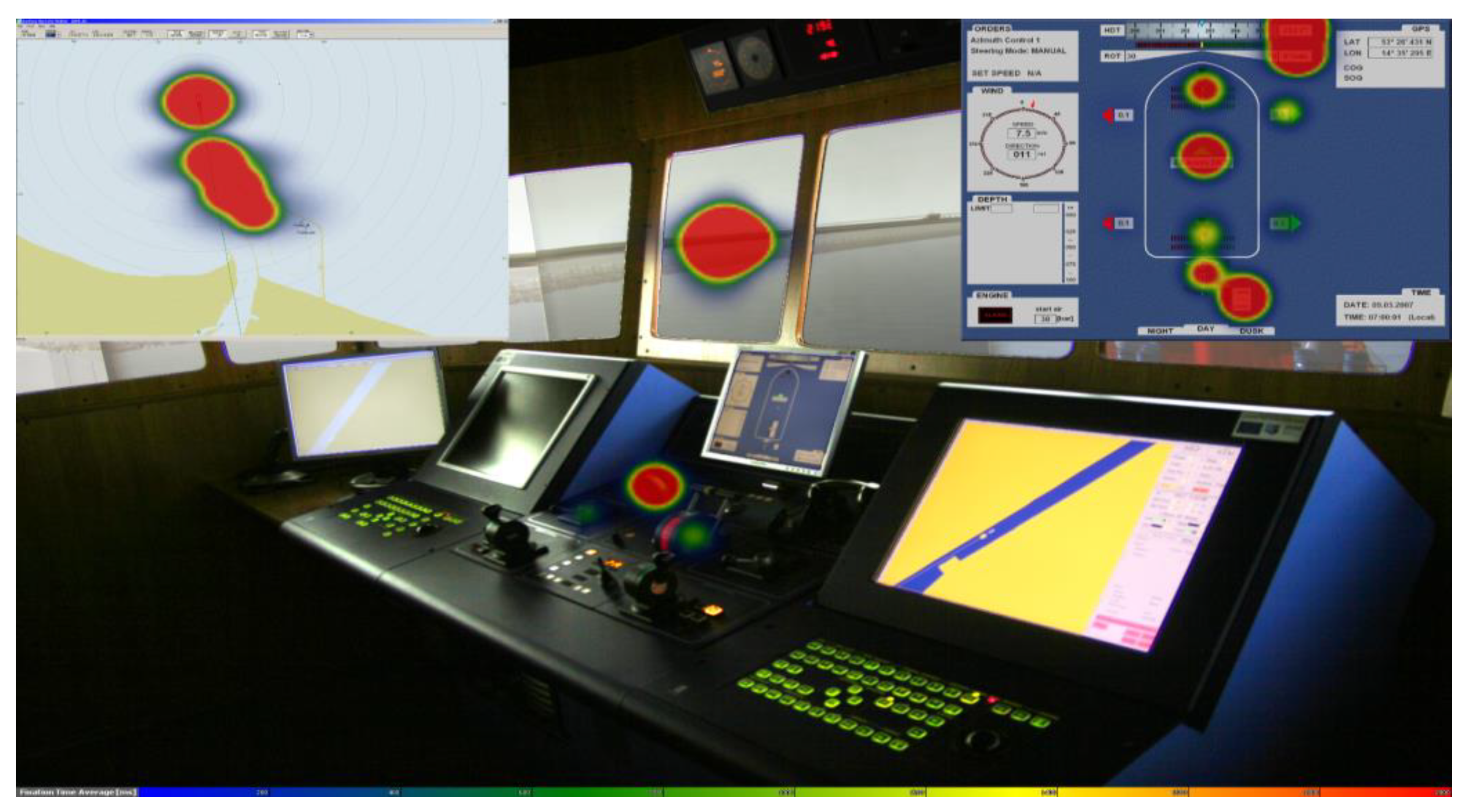
The results of tests employing eye-tracking techniques, showed that the pilot system is an area of interest (AoI) characterized by the longest total time of the navigator’s sight fixation during maneuvers in a restricted area. The selected distribution of fixation time in the form of a heat map made for a gas carrier’s passage in the area of the Outer Port of Świnoujście is presented in Figure 7.
It was also found that the distribution of the fixation spot in the AoI of the pilot system was concentrated in strictly identified places. Therefore, it was decided to examine in detail the distribution of time and place of fixation for the pilot system AoI. To this end, two areas of interest intended for the ship and the environment were separated from the general area of the pilot system (Figure 8).
This solution enabled the determination of the time and place of fixation, and relationships occurring between newly defined and the other AoI (Table 1). A certain pattern of conducting observation by the navigator emerged from an analysis of the categorized data. In the pattern, there were periodical, quick, and direct fixations (navigator did not gaze beyond the AoI of the pilot system) between the area defined for the ship and the area of the environment.
The number of direct transitions from “PNS AoI defined for ship” to “PNS AoI defined for environment”, and ending in fixation, was 2232, the other way was 2091 (Table 1, red colored cells). The values contained in the table represent the number of navigator sight passes from the AoI devices listed in the left column of the table to those specified in the header and ended with fixation. For example, the navigator, after fixing his eyesight in AoI Rudder, directed and fixed his eyes in the area of AoI Thrusters 14 times during all ship passages. In addition, the navigator looked 47 times beyond the AoI Rudder, returning to the same AoI without eye fixation in any other defined area.
A review of the research on the methods for interpreting gaze trajectory showed that such behavior is part of a pattern defining the observer’s need to assess the relative distance between the ship and the object of the environment [39].
It results from the fact that the navigator has no access to tools that carry out automatic measurement of distances to surrounding objects, without the need to handle them (e.g., move a marker or variable range marker). In such situations, the navigator often assesses the distance (assuming involuntarily the pattern of gaze trajectories) by interpolating it with reference to the known ship’s length.
Through inference based on the conducted analysis, the author concluded that it would be purposeful to provide the navigator with a tool that automatically measures and displays real distance in the 3D space between the objects of interest.
The created virtual environment expressed in the Euclidean space enables implementation of algorithms for the calculation of real distances between the spatial 3D solids of the models (as opposed to pseudoranges in commonly used two-dimensional decision support systems).
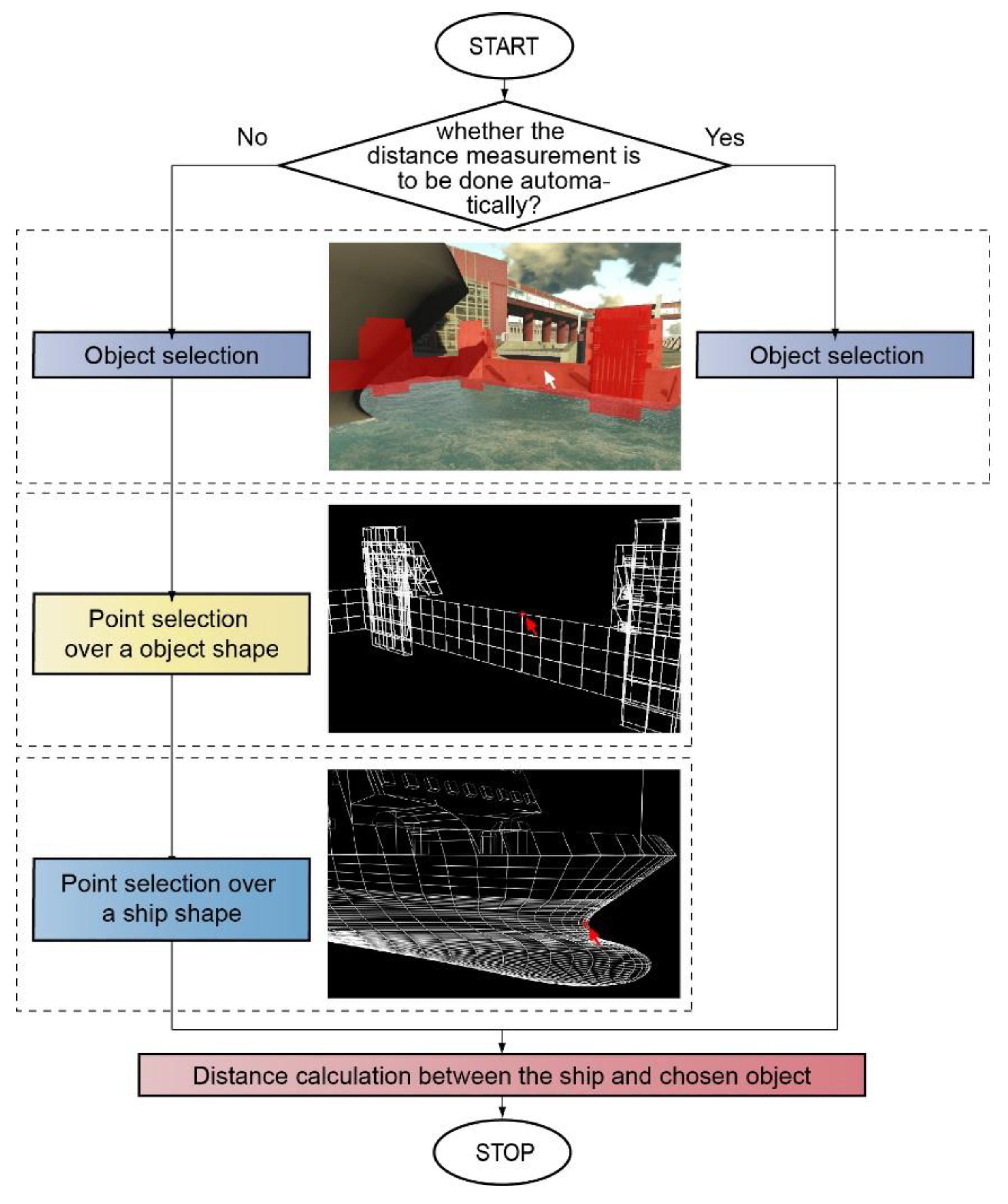
Bearing that in mind, the author decided to equip the model with a module of automatic calculations of the ship distances to the environment object, realized in two variants (Figure 9):
(1)
Distances between two points. The distance is calculated automatically in real time between two points defined by the observer. The points, with the use of an object camera, are indicated on a polygon mesh of 3D geometric model of their own ship and the selected object of the environment (left-hand loop of the algorithm in Figure 9).
(2)
The shortest distance. The distance calculated automatically in real time, between the nearest points of a polygon mesh of the ship’s model and the model of the restricted area object selected by the observer (right-hand loop of the algorithm in Figure 9).

4.4. Construction of a Model of the SDSS Augmented Interface

To ensure interaction between the above models implemented in the display method and the observer (expert), it was necessary to design and build a model of an augmented interface of the SDSS.
The main function of this model was to implement the correct process of visual thinking by the observer based on the display using the method under consideration. It was then necessary to develop an interface layout useful in terms of the content presentation on an electronic device screen.
The interface layout and its graphic form of presentation largely depend on monitor size. The AV display using synthetic cameras such as observer’s cameras, mini cameras, bird’s eye cameras, and an object camera had to assure:
  • correct depth perception and distance estimation (appropriate size of images);
  • easy handling by means of peripherals (pre-defined gestures, keyboard shortcuts, etc.);
  • meeting the requirements of the graphics pipeline in computerizing the system algorithm (limitations in texturing, mapping, number of generated image frames); and
  • possibility of displaying on a single screen (bridge work ergonomics).
The design of graphic user interfaces is a complex process beyond the scope of this paper.
The tests were selective and dictated mainly by the specifics of simulation tests (i.e., limitations in displaying at the same time all the necessary navigational information at the test station).
Navigational information presented using the developed method is assumed to supplement the standard alphanumeric data available from conventional ship devices. It should be noted that this research deals with AV-based navigational information display. From the technical point of view, this means that the dominant part of the SDSS display should be provided in AV technology.
However, due to the technological limitations of the research station, the model of the augmented interface of the SDSS had to be integrated with selected, essential alphanumeric navigational parameters of the conventional devices on the integrated bridge.
To determine the essential navigational parameters used by the observer in ship maneuvering in a restricted area, the author analyzed the data gathered during simulation tests using eye tracking techniques. To this end, the areas of interest were defined for the most important devices of the integrated bridge, located within the navigator’s sight. The total navigator’s visual fixation time recorded during 30 passages of the ship was categorized by AoI. The analysis of the results led to the determination of the most essential navigational parameters used in the navigator’s decision-making process. The quantitative distribution of 12 AoI (including visual observation of the environment), in which the longest times of fixation were recorded, is presented in Figure 10.
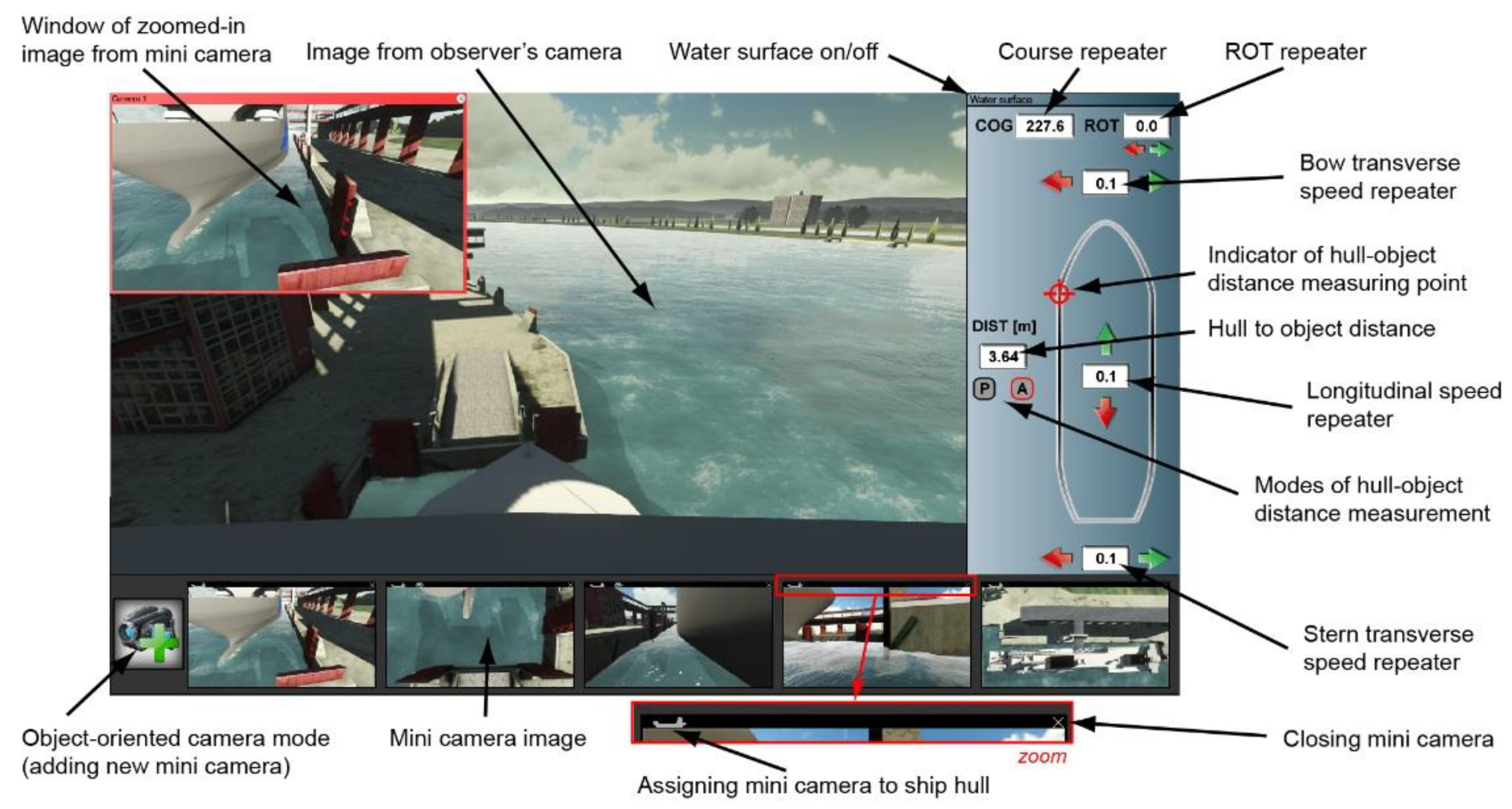
Taking account of the results, the author, due to a limited field of SDSS interface display, implemented selected navigational parameters into the model (apart from the AV display): indicators of longitudinal, transverse, and angular speed, and a heading indicator. The other navigational parameters presented in Figure 10 were displayed at the test station.
In the process of developing the model of the augmented interface, the limited computing power of the graphic system in the SDSS had to be taken into account. Rendering of developed 3D geometric models on the display monitor involves the highest hardware requirements. A large number of graphic algorithms simulating real phenomena, (which have direct impact on the assessment of distances by the navigator) may result in a blurred image. The parameter expressing the number of frames per second (fps) is a measure indicating the quality of the generated image.
Therefore, it was necessary to specify the maximum number of places from which the navigator could simultaneously observe the neighborhood in the virtual environment. In technical terms, it meant specifying the limit of the number of rendered images of a 3D scene, displayed by the mini cameras distributed in the space. Too many images displayed simultaneously on the device screen may reduce the fps to a value precluding the assessment of the navigational situation in real time. Based on a review of the relevant literature, the threshold value of the fps = 60 is commonly accepted as the value below which the quality of generated images is impaired.
To determine the limit number of simultaneously generated images from the ship’s environment, tests were conducted using the Quest 3D software. In the tests, the number of mini cameras displaying the 3D geometric models was gradually increased, combined with the simulation of graphic algorithms and the measurement of the fps parameter.
The analysis of the results showed that for five simultaneously generated images, the value of the fps parameter > 60. Accordingly, the model capability was limited to locating up to five mini cameras at the same time.
Taking into consideration the basic guidelines for the design of integrated navigational displays [40], the currently used solutions, and the results of the above analyses, the author developed a model of the augmented interface of the SDSS (Figure 11).

5. Discussion

To examine the usefulness and impact of the method of navigational information display using augmented virtuality on the safety of maneuvers, the research experiment with the use of class A, full mission bridge simulator was conducted. The ship’s bridge was equipped with commonly used SDSS shown below:
  • the ECDIS decision support system in the form of electronic navigational chart (ENC);
  • the system of decision support with navigational display realized in parallel top view projection, with a maximum contour of the vessel (analogue to the pilot systems); and
  • the system of decision support with navigational display, realized in the parallel top view projection, with the contour of the vessel on the theoretical plane of contact with the shore–ship collision contour (analogue to the pilot and docking systems).
and the SDSS with implemented method described in the paper.
In the experiment, navigators—chief officers and captains participating in training courses at the time—executed a series of ship passages in various maneuvering scenarios such as berthing alongside of the container ship; berthing at an angle to the quay of the general cargo ship; bow-to-shore berthing of the ferry; turnings of the cruise ship; and also unberthing and turning of the tow train (sea barge with two tugs).
The recorded ship movement parameters were compared for various criteria of navigational safety. The following criteria were assumed as the assessment measure of the simulated ship passages, depending on the variant of passages in the simulation experiment:
  • the primary (superior) criteria for the assessment of navigational safety, i.e.,
    • the average maneuvering area of the ship, estimated for the confidence coefficient 0.95;
    • maximum maneuvering area of the ship;
    • resultant value of vessel speed determined at the moment of ship’s hull contact with a fender (modified criterion of kinetic energy of first contact with the shore); and
    • the value of the minimum distance of ship’s hull from the navigational obstacle.
  • the auxiliary (subordinate) criterion for assessing the efficiency of maneuvering (i.e., maneuvering time length).
In general terms, the experiment showed that the use of the method under consideration, in most of the maneuvers performed, had a statistically significant impact on the safety of navigation in restricted waters (in comparison to maneuvers with other selected systems). The results of the simulation experiment indicate that application of the method in five variants out of six increased navigational safety, while in the remaining variant, the difference of the values of the parameters of the compared criteria was not statistically significant (the mean distribution of the resultant speed at the moment of the container ship makes contact with the fender and the random variable of maneuvering time do not differ significantly with the mean distribution of the same variables obtained for the variants using only visual observation and other systems).
The results of the analysis that led to the formulation of the following general conclusions concerning the presented method has significant impact on navigational safety indicators when:
  • the place of the ship’s hull contact with the collision object is not in the observer’s sight (is in an obscured or inaccessible place) or the prevailing conditions of reduced visibility exclude visual observation; and
  • the lines of the cross- and longitudinal-sections of the hull and the collision object in the surroundings at the point of contact have a complex shape, different to the rectangle or where in the orthogonal top view the edge of the ship’s contact with the collision object is obscured by any sectional plane (of the ship or object).
The method has no significant impact on navigational safety indicators when the place of the ship’s hull contact with the collision object remains within the sight range and is visible for the navigator, similar to that when the lines of cross- and longitudinal-sections of the hull and the collision object at that place have an uncomplicated, exactly, or roughly rectangular shape.

6. Conclusions

The application of AV in the method enabled a faithful representation of the actual environment on an electronic device screen by displaying it using 3D virtual models.
The construction of a model of an AV-based navigational information display aims to provide the navigator with reliable information on time-varying ship’s 3D position relative to surrounding objects during maneuvers in a restricted area in various visibility conditions.
To achieve the main research objective, the developed model of navigational information display was built on AV technology. The component models were created to ensure correct positioning and orientation of 3D geometric models of a selected restricted area and vessels. Furthermore, a model of selective navigational information presentation was created to allows the navigator to perform multi-level assessment of the navigational situation in restricted area maneuvers, particularly in the phase of ship-to-shore operations.
The developed models were implemented into a model of the interface of the navigator’s SDSS. The information display methods used in the system should offer the navigator practicably the highest level of environment identification through correct perception of the environment depth and estimation of distances to collision objects.
The problem of assessing the safety of ship maneuvers based on SDSS indications in the method of 3D navigational information display (e.g., using AV) seems to be particularly relevant and up-to-date. Possibilities of semi/autonomous movement and remote ship control are being explored and discussed within the EU, while new directions of development such as remote pilotage are being defined for the SDSS.
The developed method was verified through assessment of the impact of the system on some navigational safety indicators during specific maneuvers of vessels in a restricted area. To this end, the created SDSS model using AV technology was integrated with a non-autonomous simulation model of the ship movement, Polaris™, operating in real time. The detailed results of the research will be published by the author in the near future.

Funding

This research outcome was achieved under the research project no. 1/S/CIRM/16 financed from a subsidy of the Polish Ministry of Science and Higher Education for statutory activities of the Maritime University of Szczecin.

Conflicts of Interest

The authors declare no conflict of interest.

References

  1. Rozkrut, D. Statistical Yearbook of Maritime Economy 2018; Główny Urząd Statystyczny: Warszawa, Poland, 2018. [Google Scholar]
  2. Flacke, J. Spatial Decision Support Systems—Introduction to Concepts and Requirements; Technical Skills Course: Web-GIS and Spatial Data Infrastructure CHANGES Project: Dortmund, Germany, 2012. [Google Scholar]
  3. Swanson, J. The Cartographic Possibilities of VRML, Multimedia Cartography; Springer: Berlin/Heidelberg, Germany, 1999; pp. 181–194. [Google Scholar]
  4. Porathe, T. Improved situation awareness in navigation using egocentric view 3-D nautical charts. In Proceedings of the 16th International Ergonomic Association’s World Congress, Maastricht, The Netherlands, 10–14 July 2006; Elsevier: Holland, The Netherlands, 2006. [Google Scholar]
  5. Ford, S.F. The first three-dimensional nautical chart. In Undersea with GIS; ESRI Press: Redlands, CA, USA, 2002; pp. 117–138. [Google Scholar]
  6. Łubczonek, J.; Trojanowski, J.; Włodarczyk-Sielicka, M. Zastosowanie trójwymiarowego zobrazowania informacji nawigacyjnej w mapach elektronicznych dla żeglugi śródlądowej. Archiwum Fotogrametrii Kartografii i Teledetekcji 2012, 23, 261–269. [Google Scholar]
  7. Gold, C.; Góralski, R. 3D Graphics applied to maritime safety. In Information Fusion and Geographic Information Systems; Springer: Berlin/Heidelberg, Germany, 2007; pp. 286–300. [Google Scholar]
  8. Blast Project. Bringing Land and Sea Together—Blast Project: State of the Art and Data Audit for North Sea Region; Danish National Survey and Cadastre: Copenhagen, Denmark, 2011. [Google Scholar]
  9. Carbajosa, J.; Lozano, J.J.; Velásquez, S.; Wittkuhn, D.; Zahharov, M.; Ehrke, K.C.; Abreu, J.; Marques, R. EPDIS: The electronic pilot book display system. Trans. Built Environ. 2005, 373–381. [Google Scholar] [CrossRef]
  10. Brennan, R.T.; Ware, C.; Alexander, L.; Armstrong, A.; Mayer, L.; Huff, L.; Calder, B.; Smith, S.; Plumlee, M.; Arsenault, R.; et al. The electronic chart of the future: The hampton roads demonstration project. In Proceedings US Hydro Conference; University of New Hampshire: Durham, NH, USA, 2003. [Google Scholar]
  11. Bentzen, M.; Borup, O.; Christensen, T. The efficiensea e-navigation approach–filling the gap. In Proceedings of the E-Navigation Underway: International Conference on E-Navigation, Copenhagen, Denmark, 31 January–2 February 2011; EMA: Amsterdam, The Netherlands, 2012; pp. 14–28. [Google Scholar]
  12. Ternes, A.; Knight, P.; Moore, A.; Regenbrecht, H. A user-defined virtual reality chart for track control navigation and hydrographic data acquisition. In Geospatial Vision; Springer: Berlin/Heidelberg, Germany, 2008; pp. 19–44. [Google Scholar]
  13. Arsenault, R.; Plumlee, M.; Smith, S.; Ware, C.; Brennan, R.; Mayer, L.A. Fusing Information in a 3D Chart-of-the-Future Display; US Hydro: Biloxi, MS, USA, 2003. [Google Scholar]
  14. Hugues, O.; Cieutat, J.-M.; Guitton, P. An experimental augmented reality platform for assisted maritime navigation. In Proceedings of the 1st Augmented Human International Conference, Megève, France, 2–3 April 2010; ACM Press: New York, NY, USA, 2010. [Google Scholar]
  15. Raymarine, Raymarine E-Series. 2019. Available online: http://www.raymarine.com/view/index-id=2966.html (accessed on 2 January 2020).
  16. Garmin, Garmin Mariner 3D. 2019. Available online: https://www.garmin.com/en-GB/maps/bluechart/ (accessed on 2 January 2020).
  17. C-Map, C-Map 4D. 2019. Available online: https://lightmarine.c-map.com/chart-plotters/c-map-4d (accessed on 2 January 2020).
  18. AAWA. Remote and Autonomous Ships—The Next Steps, Espoo: AAWA—Advanced Autonomous Waterborne Applications Initiative; Rolls-Royce plc: London, England, 2016. [Google Scholar]
  19. MUNIN. D9.3: Quantitative Assessment, s.l.: MUNIN—Maritime Unmanned Navigation through Intelligence in Networks; Fraunhofer-Gesellschaft: Munich, Germany, 2015. [Google Scholar]
  20. Batalden, B.M.; Leikanger, P.; Wide, P. Towards autonomous maritime operations. In Proceedings of the 2017 IEEE International Conference on Computational Intelligence and Virtual Environments for Measurement Systems and Applications (CIVEMSA), Annecy, France, 26–28 June 2017; IEEE; pp. 1–6. [Google Scholar]
  21. Kutsuna, K.; Ando, H.; Nakashima, T.; Kuwahara, S.; Nakamura, S. NYK’s approach for autonomous navigation–structure of action planning system and demonstration experiments. J. Phys. Conf. Ser. 2019, 1357, 12013. [Google Scholar] [CrossRef] [Green Version]
  22. Бoшкoв, И.И.; Крутикoва, А.А. Системы дoпoлненнoй реальнoсти для мoрскoй навигации. Int. Sci. J. Symb. Sci. 2018, 8, 1–8. [Google Scholar]
  23. Lurås, S. Systemic Design in Complex Contexts: An Enquiry through Designing a Ship’s Bridge; Oslo School of Architecture and Design: Oslo, Norway, 2016. [Google Scholar]
  24. Haase, K.; Koch, R. Extension of sea charts for 3D visualization. In ISPRS Proceedings, 3DGeoInfo Conference; ISPRS; Aachen, Germany, 2010. [Google Scholar]
  25. Benton, C. Augmented Reality for Maritime Navigation: The Next Generation of Electronic Navigational Aids. In Proceedings of the 7th Marine Transportation System Research & Technology Coordination Conference, Washington, DC, USA, 16–17 November 2004. [Google Scholar]
  26. Spears, T. 2012. Available online: https://www.designboom.com/technology/rolls-royce-ox-bridge-autonomous-vessel-12-15-2014/ (accessed on 2 January 2020).
  27. Raymarine, Raymarine ClearCruiseAR. 2019. Available online: http://www.raymarine.com/clearcruise.html (accessed on 2 January 2020).
  28. Ahuja, G.; Pacis, E.B.; Sights, B.; Fellars, D.; Everett, H.R. Layered Augmented Virtuality; Space and Naval Warfare Systems Command: San Diego, CA, USA, 2007. [Google Scholar]
  29. Rackliffe, N. An Augmented Virtuality Display for Improving UAV Usability; Brigham Young University: Brigham, MA, USA, 2005. [Google Scholar]
  30. Sanguino, T.J.M.; Márquez, J.M.A.; Carlson, T.; Millán, J.D.R. Improving skills and perception in robot navigation by an augmented virtuality assistance system. J. Intell. Robot. Syst. 2014, 76, 255–266. [Google Scholar] [CrossRef]
  31. Milgram, P.; Kishino, F. A taxonomy of mixed reality visual displays. IEICE Trans. Inf. Syst. 1994, 77, 1321–1329. [Google Scholar]
  32. Tamura, H.; Yamamoto, H.; Katayama, A. Mixed reality: Future dreams seen at the border between real and virtual worlds. IEEE Comput. Graph. Appl. 2001, 21, 64–70. [Google Scholar] [CrossRef] [Green Version]
  33. Milgram, P.; Takemura, H.; Utsumi, A.; Kishino, F. Augmented reality: A class of displays on the reality-virtuality continuum. Photonics Ind. Appl. 1995, 282–292. [Google Scholar] [CrossRef]
  34. Vasiljević, A.; Borović, B.; Vukić, Z. Augmented reality in marine applications. Brodogradnja 2011, 62, 136–142. [Google Scholar]
  35. Azuma, R.T. A survey of augmented reality. Presence 1997, 6, 355–385. [Google Scholar] [CrossRef]
  36. Miller, H.L.; Bugnariu, N.L. Level of immersion in virtual environments impacts the ability to assess and teach social skills in autism spectrum disorder. Cyberpsychol. Behav. Soc. Netw. 2016, 19, 246–256. [Google Scholar] [CrossRef] [PubMed] [Green Version]
  37. Holmqvist, K.; Nyström, M.; Andersson, R.; Dewhurst, R.; Jarodzka, H.; Van de Weijer, J. Eye Tracking: A Comprehensive Guide to Methods and Measures; OUP: Oxford, UK, 2011. [Google Scholar]
  38. Gralak, R. Assumptions to the selective system of navigational-maneuvering information presentation. Int. J. Mar. Navig. Saf. Sea Transp. 2011, 5, 433–438. [Google Scholar]
  39. Wartenberg, C.; Wiborg, P. Precision of exocentric distance judgments in desktop and cube presentation. Teleoper. Virtual Environ. 2003, 12, 196–206. [Google Scholar] [CrossRef]
  40. Yang Young-Hoon, L.B.-W. A study on the design of ergonomic bridge conning display. J. Korean Soc. Mar. Environ. Saf. 2005, 11, 2. [Google Scholar]
Figure 1. The continuum of the real and virtual worlds.
Jmse 08 00237 g001
Figure 2. The test areas of the simulation experiment: (a) open sea area; (b) restricted area.
Jmse 08 00237 g002
Figure 3. The use of eye-tracking technology in the research experiment.
Jmse 08 00237 g003
Figure 4. The location of areas of interest (AoIs) identified for the preliminary experiment.
Jmse 08 00237 g004
Figure 5. The location of AoIs defined for the preliminary experiment.
Jmse 08 00237 g005
Figure 6. The distribution of the observer’s field of vision during maneuvers in an open sea area and restricted sea area.
Jmse 08 00237 g006
Figure 7. Heat map fixation time distributions: a gas tanker passage in a restricted area.
Jmse 08 00237 g007
Figure 8. The areas of interest intended for the ship and the environment related to the pilot system.
Jmse 08 00237 g008
Figure 9. The algorithm of the procedure for the automatic measurement of distance between the ship’s hull and the object.
Jmse 08 00237 g009
Figure 10. The percentage distribution of the navigator’s visual fixation on the most frequently used shipboard devices during maneuvers in a restricted area.
Jmse 08 00237 g010
Figure 11. The augmented interface of the SDSS.
Jmse 08 00237 g011
Table 1. The number of fixations for mooring, turning, and fairway passage in the areas of interest.
RudderThrottleThrustersVisual Observation of the EnvironmentRudder IndicatorThrottle IndicatorCOGROTBow Thruster IndicatorStern Thruster IndicatorSway IndicatorSurge IndicatorPNS_AoI Defined for ShipPNS_AoI Defined for Environment
Rudder4731454200013373
Throttle9245174113501012383216
Thrusters14203591419014829146237
Visual observation of the environment2621357040716133015022716851
Rudder indicator1716522755022123361144
Throttle indicator292765433401101346133328
COG0003001814312100
ROT01337241511850212068
Bow thruster indicator03453112013716444857124
Stern thruster indicator0143131000032212324
Sway indicator010198956622285794611704311
Surge indicator1262014958109016110142339399532
PNS_AoI defined for ship533579283051613175742223
PNS_AoI defined for environment1028519715051343665209600