Article

Self-Excited Torsional Vibration in the Flexible Coupling of a Marine Propulsion Shafting System Employing Cardan Shafts

1
Division of Marine Engineering, Mokpo National Maritime University, Mokpo 58628, Korea
2
Division of Marine Information Technology, Korea Maritime and Ocean University, Busan 49112, Korea
*
Author to whom correspondence should be addressed.
J. Mar. Sci. Eng. 2020, 8(5), 348; https://doi.org/10.3390/jmse8050348
Submission received: 21 April 2020 / Revised: 3 May 2020 / Accepted: 7 May 2020 / Published: 13 May 2020

Abstract

:
The reliability of propulsion shafting systems is a major concern for ocean-going vessels because mid-ocean repairs can be time-consuming and spare parts must be available. To address this concern, vibration modeling and experimental measurements were conducted on a propulsion shafting system with a Z-drive propeller, with the objective of identifying the source of failure for the flexible rubber coupling connecting the diesel engine with the intermediate shaft. The torsional fluctuations in the flexible coupling dramatically increased and then abruptly ceased. The modeling results revealed that the frictional losses during power transmission through the universal joints could act as an excitation force for self-excited vibration. The coupling connected to the intermediate shaft did not have sufficient radial flexibility to dampen these vibrations. To avoid the effects of the self-excited torsional vibration, it is recommended that this coupling is replaced with one that is capable of absorbing the radial shaft displacement.

1. Introduction

Certain marine propulsion applications require efficient maneuverability under extreme conditions. One solution for this issue is the use of a Z-drive propeller, which may rotate freely to alter the direction of the thrust applied to the vessel. However, such a propulsion system is known to be subject to self-excited vibrational modes, which may damage the system. In propulsion shaft systems, self-excited vibrations are produced by an unstable rotary power transmission mechanism. Such vibrations begin spontaneously, and the amplitude increases until a nonlinear effect limits any further increase. There are many sources of self-excitation, and in most cases, the self-excited vibrations pose a danger to the entire propulsion system. The force acting on the vibrating mechanism is typically external to the system and independent of the motion within the system. Friction-induced vibration [1,2,3,4,5] and flow-induced vibration [6,7,8] are examples of self-excited vibration.
Moreover, self-excited vibrations are characterized by the presence of a mechanism whereby the system vibrates at its own natural or critical frequency, mostly independent of the frequency of any external stimulus [9]. Lee et al. investigated the unstable torsional vibration resulting from the friction torque that occurred in a propulsion shafting system [10]. They observed that in the operating mode wherein the shaft generator is separated, the clutch should be entirely disengaged. However, if the clutch between the rubber coupling and the shaft generator is not fully disengaged, then friction torque occurs because the shaft generator is idling. During the torsional vibration experiment, significant vibrations occurred but were not associated with the excitation of the diesel engine. As measured, the self-excited torsional vibrations (SETVs) were oscillating at a frequency of 3.75 Hz, similar to the shaft generator’s idle running speed (220–250 r/min) [11].
In another experiment, torsional vibrations developed in an electric system equipped with an inverter motor to drive a propeller [12,13]. The torsional vibration analysis identified that the resonant point was located on the flexible rubber coupling, which was employed to transmit the torque from the electric motor to the intermediate shaft and reduce the influence of the motor assembly on the propeller components. This resonance added to the increased dominant vibration at an approximately identical frequency. The alternating tension and compression action during the damping process of the coupling were investigated as the source of this phenomenon. The rubber element could sustain simultaneous compression, shear, and torsion stresses, but could not fully dissipate or absorb the generated torsion at certain speed ranges.
Furthermore, a fractured Cardan shaft was observed in the propulsion system using a Z-drive propeller [14]. This failure was not likely caused by the torque variation from the main engine, but is instead attributed to the SETV from the friction torque of the Cardan shaft. However, this was not confirmed owing to the lack of vibration measurements. In this study, the repeated failure of a flexible rubber coupling in a similar vessel with a Z-drive propeller was investigated using torsional vibration theory and global vibration and torsion measurements. The coupling is considered to have provided insufficient radial flexibility in the damping process. The experimental methodology is described in the next section. The main results are presented and discussed in Section 3. Finally, the major findings and conclusions of this study are presented in Section 4.

2. Materials and Methods

2.1. Case Study

In this study, the case of a propulsion shafting system on a 150-ton class oil-skimmer vessel was investigated. A Z-drive propeller, powered by a high-speed diesel engine through two sets of Cardan shafts, was used. A flexible rubber coupling was employed to isolate the vibratory torque excited by the diesel engine and the excess hydraulic variation of the propeller owing to external impact [10,15,16]. Hence, the diesel engine and the reduction gears could be safely operated by adapting the flexible coupling to the system [17]. However, the flexible coupling repeatedly failed during regular operation. Notably, the same type of new coupling was used, and a few external conditions were changed to improve the performance. The failed coupling is shown in Figure 1. The operating engineer reported abnormal noise, and vibration occurred immediately before the incident. Many experiments were performed, but abnormal vibrations were not observed. Further analysis was not possible until the next vessel in the same series was built, and the experiment could be repeated.

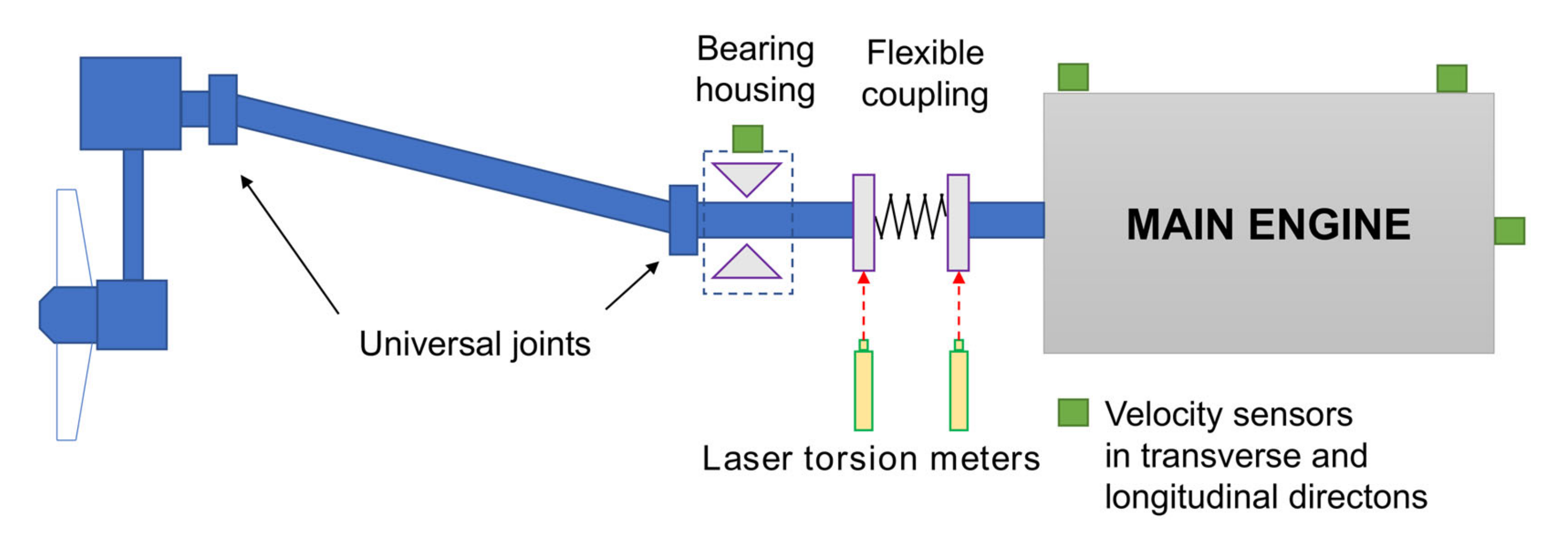
2.2. Vibration Measurements

The schematics of the propulsion system and experimental setup are shown in Figure 2. To verify the torsional vibration, laser rotary torsional meters were installed onto both ends of the flexible coupling. Subsequently, the angular velocity was measured, and the relative torsion angle was calculated, as required. To evaluate the structural vibration, velocity sensors were installed onto the bearing housing and onto the fore and aft ends of the engine body. Then, measurements were taken while the engine accelerated and decelerated.

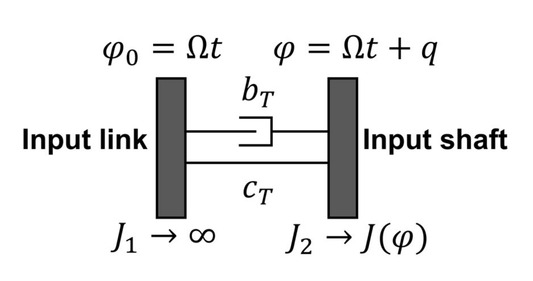
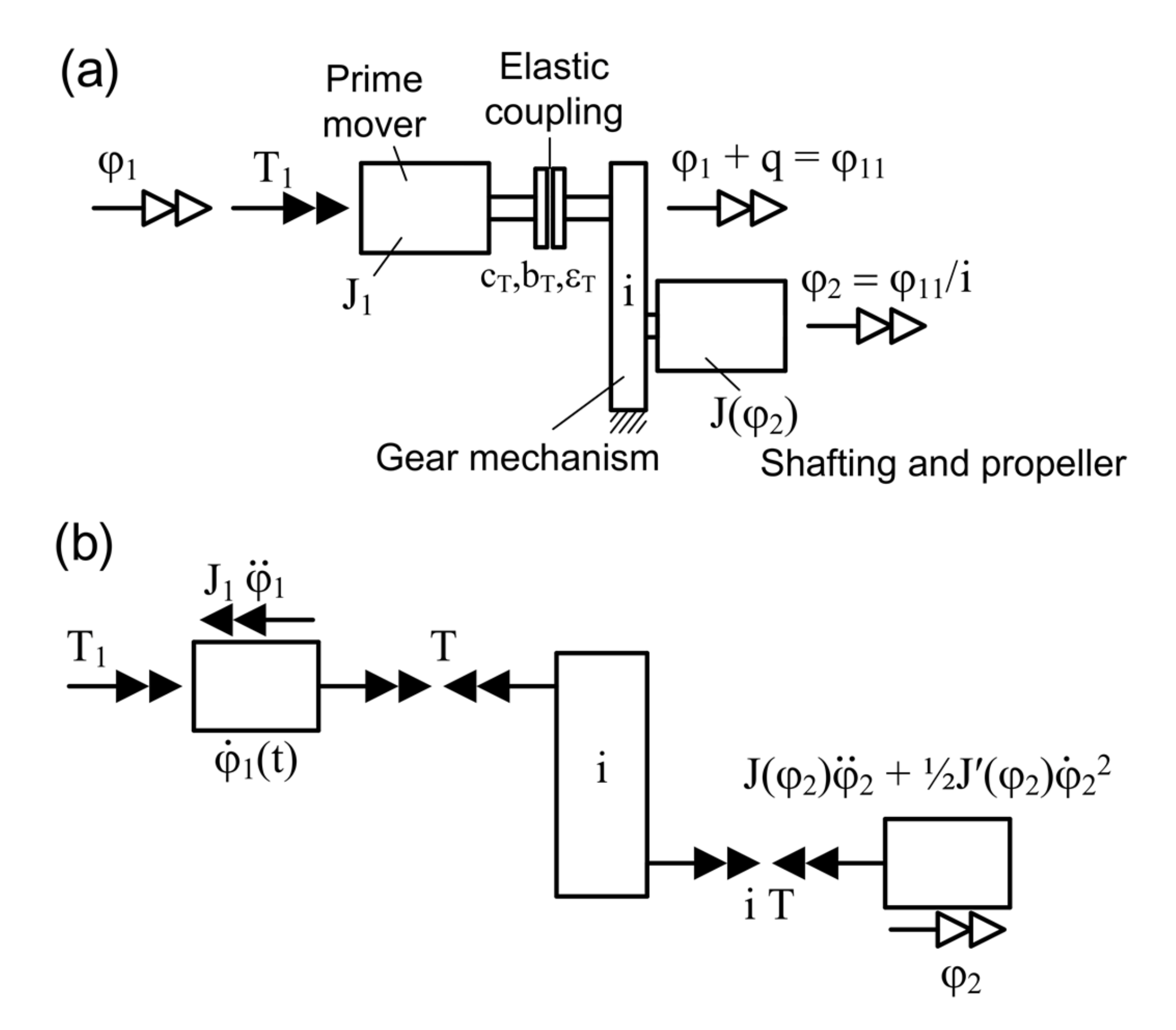
2.3. Self-Excited Torsional Vibration Theory

The model for calculating the SETV is shown in Figure 3. The model consists of an input link rotating at constant angular velocity, connected to an input shaft with a variable moment of inertia, and depending on the position of the input link. The nonlinear motion equation, considering the elasticity and damping of the input shaft, is expressed as follows [18]:
J φ φ ¨ + 1 2 · d J φ d φ φ ˙ 2 + c T φ φ 0 + b T φ ˙ φ ˙ 0 = 0
The rotational motion is calculated as follows:
φ = φ 0 + q = Ω t + q ;               φ ˙ = Ω + q ˙ ,               φ ¨ = q ¨
If the relative angle of rotation, q, is assumed to be very small, linearization is allowed. The Taylor Series expansion of the input shaft inertia moment can be expressed as follows:
J φ = J Ω t + J Ω t q +
d J φ d φ = J Ω t +   J   Ω t q +
By inserting Equations (3) and (4) into Equation (1), the linear differential equation with J = J   Ω t can be rewritten as follows:
J q ¨ + b T + J Ω q ˙ + c T + J Ω 2 / 2 q = 1 2 J Ω 2
In this case, all terms starting from order q 2 are ignored. The decay rate, δ t , and natural frequency, ω 0 t , can be expressed, respectively, as follows:
δ t = b T + J Ω 2 J
and
  ω 0 2 t = c T + J Ω 2 2 J
The elastic coupling with nonlinear characteristics has a significant effect on the drive system and is primarily used to lower the natural frequency range. The theoretical simulation can be represented as the numerical integration of the nonlinear motion equation.
The diagram of the drive system is shown in Figure 4a. The moment of inertia, J1, as the prime mover (engine side) is connected to the propeller with a nonlinear flexible coupling, which has a reduction transmission ratio i = φ 11 / φ 2 . The reduced moment of inertia of the Z-drive (driven side) is expressed as follows:
J φ 2 = J 0 1 + μ sin 2 φ 2 ,    
d J d φ 2 = 2 J 0 μ sin φ 2 cos φ 2
Therefore,
q = φ 11 φ 1 = i φ 2 φ 1
Then, the restoring torque, T, of the flexible coupling is calculated as follows:
T = c T q + ϵ T q 3 + b T q ˙
The primary point of interest is the dynamic load of the flexible coupling of the starting and braking processes. From Figure 4b, the motion equation can be expressed using the torque balance of both shafts, as follows:
J 1 φ 1 ¨ T = T 1
φ 2 φ ¨ 2 + 1 2 J φ 2 φ 2 2 ˙ = i T
To solve the nonlinear differential equation for φ 1 and φ 2 , Equations (8), (9), and (11) can be inserted into Equation (13) to obtain the following relationship:
J 0 ( 1 + μ sin 2 φ 2 ) φ ¨ 2 + 1 2 J 0 μ sin 2 φ 2 φ 2 2 ˙ = i [ c T q + ϵ T q 3 + b T q ] ˙
The nonlinear differential equation for q can be expressed as follows:
q ¨ = φ ¨ 1 i 2 c T q + ϵ T q 3 + b T   q ˙ 1 2 J 0 μ sin 2 φ 1 + q i φ 1 ˙ + q ˙ 2 i J 0 + J 0 μ sin 2 φ 1 + q i
The function for angle φ 1 t can be used to numerically integrate Equation (15) for the predefined initial conditions, from which q t and q ˙ t are obtained. Then, the coupling torque can be calculated from Equation (11) and the angle φ 2 can be calculated from Equation (10). From φ 2 , the input torque, T 1 t , which is required to produce the motion from Equation (12), can be calculated.
The Cardan shaft mechanism is illustrated in Figure 5. The shaft operates at slope angle β ; the angular velocity and angular acceleration on the driven side are expressed as Equations (16) and (17), respectively.
Ω 2 = cos β   ·   Ω 1 1 sin 2 α 1   ·   sin 2 β
a 2 = cos β   ·   a 1 1 sin 2 α 1   ·   sin 2 β + Ω 1 2   ·   cos β   ·   sin 2 β   ·   sin 2 α 1 ( 1 sin 2 α 1   ·   sin 2 β ) 2

3. Results and Discussion

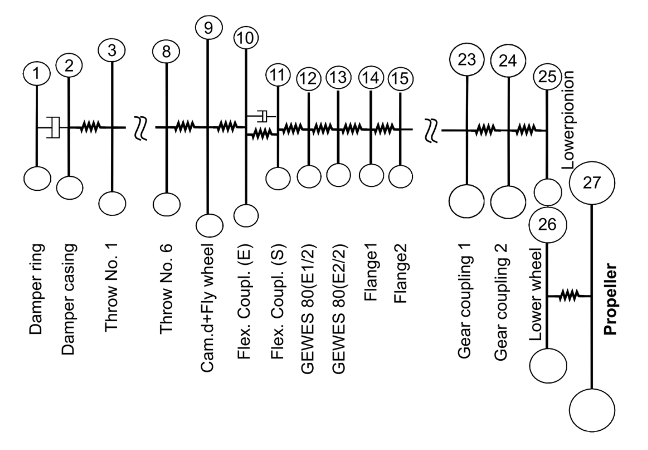
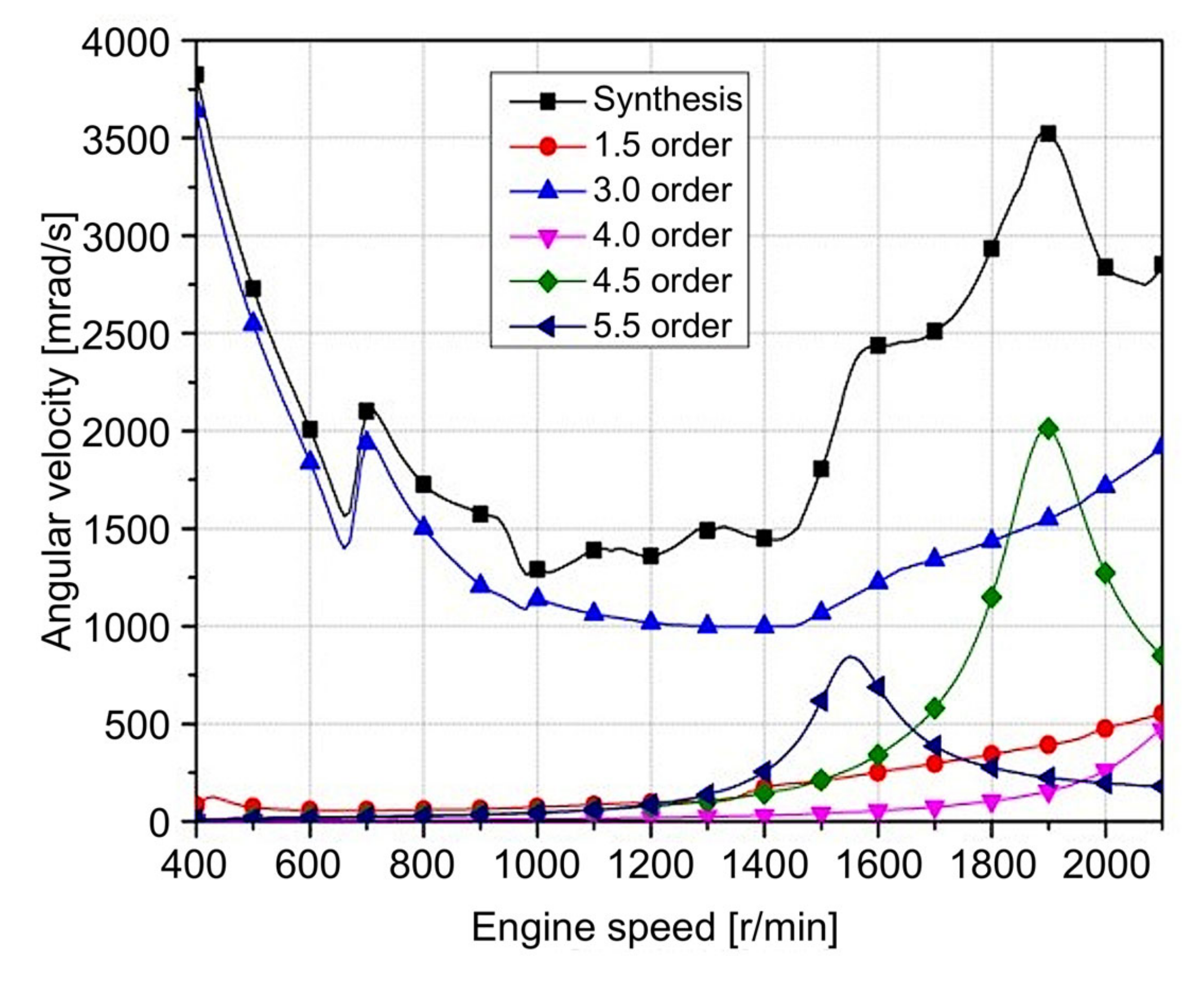
3.1. Torsional Vibration Calculations

In this study, the propulsion system on the 150-ton class oil-skimmer vessel was powered by a 4-stroke high-speed diesel engine as the prime mover. There were five intermediate shafts with two sets of Cardan shafts. In the stern space area, integrated reduction gears were installed onto the top of the Z-drive propeller (see Table A1 in Appendix A for system specifications).
The Vulkan flexible rubber coupling was installed between the main engine and the intermediate shaft. Its outer ring was directly connected to the flywheel, while its inner ring was coupled to the intermediate shaft. Based on the technical data provided by the coupling manufacturer [19], the propulsion shafts were modeled as 27 concentrated masses (Figure 6), and the torsional vibration calculation was performed by assuming that the coupling stiffness was 100% of the engine load. The analysis was carried out using our proprietary software. The calculation results are presented in Table 1. The torsional vibration characteristic at the flexible coupling with all cylinders firing normally is presented in Figure 7. The theoretical calculation results for the torsional vibration presented no issues compared with the measurement results.
The 1st order vibration was not observed in the calculation because each cylinder had an equal load, and the crank firing angles were arranged at equal intervals. Furthermore, the vibration of the 3rd order component (the vibration phase angle between the banks was 90°) was dominant because a V-type 12-cylinder engine was used. In the theoretical approach, all concentrated masses of the propulsion shafting were converted to the reduced model of a 2-mass system based on the elastic coupling and I node natural frequency [20]. In this case, the equivalent moment of inertia, J 1 , of the diesel engine was 3.62   k g · m 2 , the equivalent inertia, J 0 , of the propulsion system was 2.091   k g · m 2 , the equivalent torsional rigidity, c T , was 5.8   k N · m / r a d , and the torsional attenuation, b T , was 15.77   N · m · s / r a d . Additional vibration elements were predicted by changing the values of Equation (15). Because these elements are complex and difficult to calculate, in this study, the abovementioned values of Equation (15) were replaced with the experimental results.

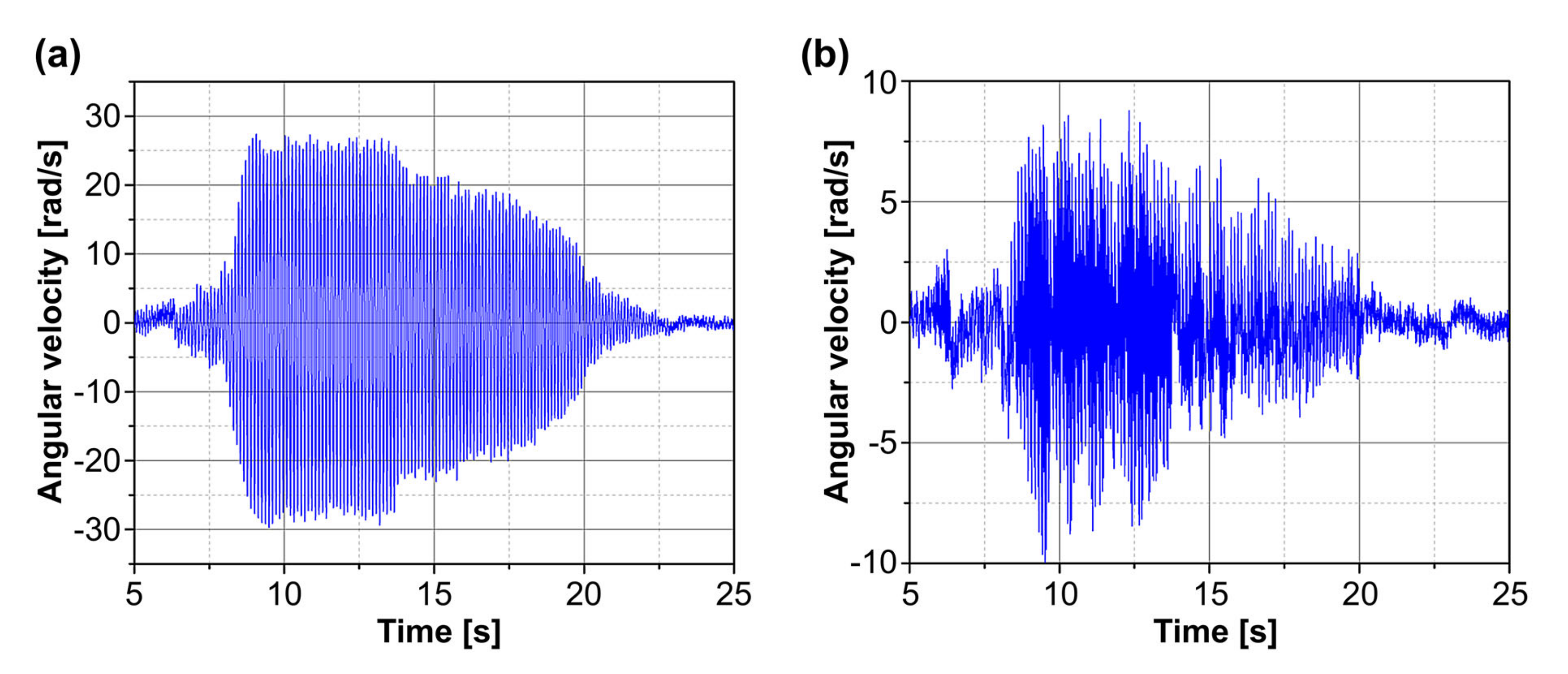
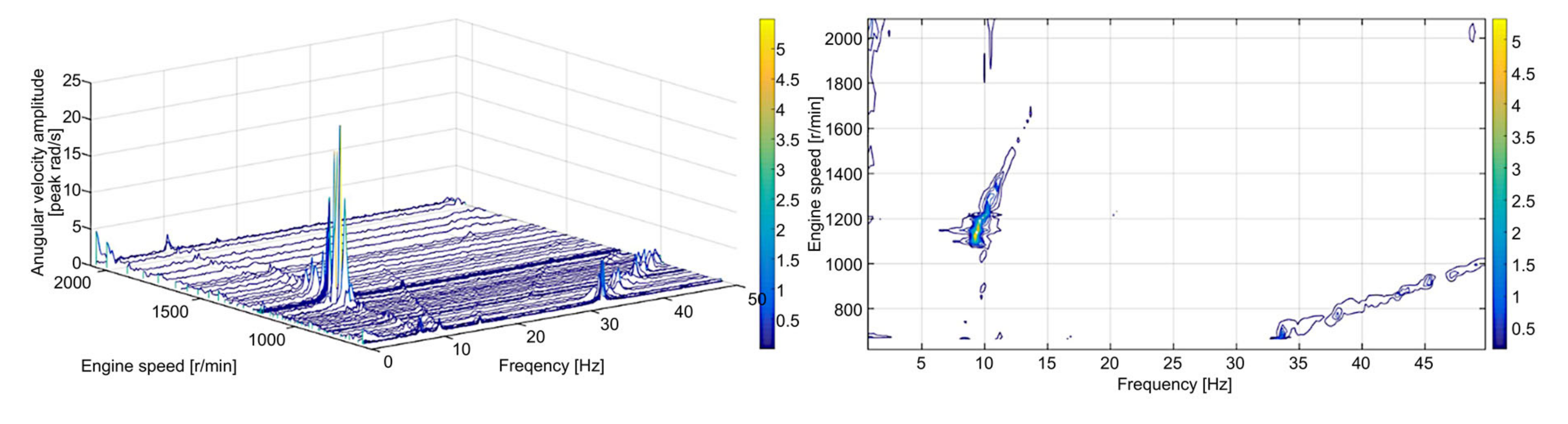
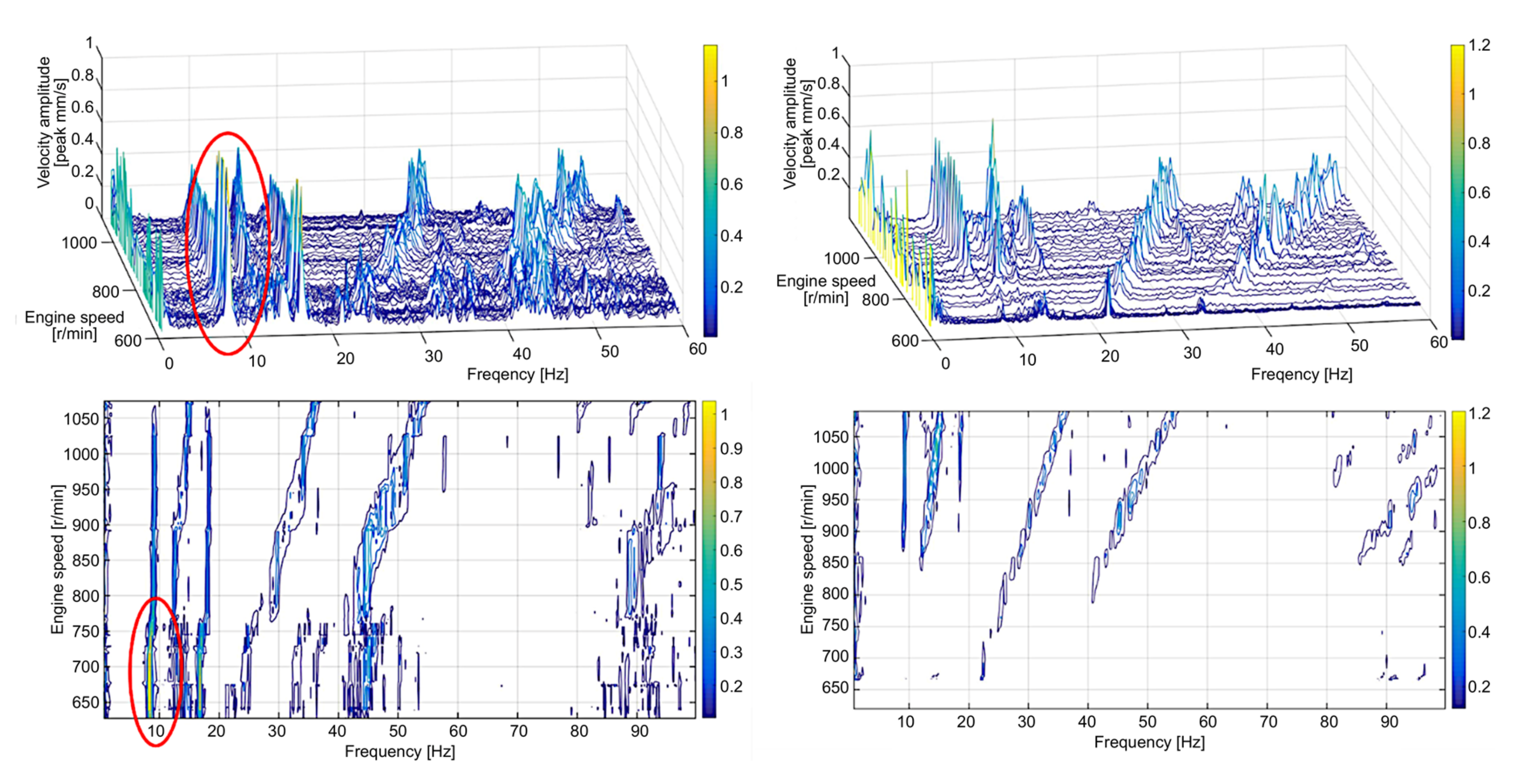
3.2. Vibrational Measurements

The angular velocity fluctuations during engine acceleration at the ends of the flexible coupling on the engine and Cardan shaft side are plotted in Figure 8 and Figure 9, respectively. The time-domain indicates that the dominant SETV mode occurred in approximately 15 s, significantly increased when the engine speed exceeded 600 r/min, and then decreased above 800 r/min before disappearing. The results indicate that the dominant mode of the torsional vibration was 8.7 Hz or 522 cycles/min, which is slightly below the 1-node natural frequency of 631 cycles/min, as presented in Table 1. As illustrated in Figure 9, the dominant vibration mode was the 1st order at the natural frequency on the engine side of the coupling. The end on the side closest to the Cardan shaft was the 2.5th order mode, which is the major component, while the 1st order mode is much smaller. Therefore, by ignoring the angular velocity vibration on the shaft side of the coupling, the maximum angular acceleration was calculated as 1531 rad/ s2 by applying the value measured on the engine side of the coupling to Equation (15).
The data collected during engine deceleration are presented in Figure 10. As the engine speed slowly decreased from 2200 r/min to the minimum speed, the 0.5th order resonance of 9–10 Hz occurred while the engine ran at approximately 1000–1200 r/min, which is a smaller amplitude. Additionally, the structural vibrations of the bearing housing close to the universal joint had a dominant vibration mode in the same frequency range of 9–10 Hz, as shown in Figure 11. This result confirmed that the vibration excitation frequency is a SETV that does not depend on the engine speed. The engine body vibrations were more intense when SETVs occurred. Furthermore, SETV still occurred when one cylinder misfired, but it did not bounce, unlike the last time it was recorded.
The bouncing vibration did not occur often; hence, shafting misalignment was excluded as a possible cause. Furthermore, these phenomena did not behave in the same manner as the misalignment. The universal joint consists of a cross/yolk mechanism. Based on the authors’ experience, the only possible source of vibration could be the friction torque in the Cardan shaft universal joint. Friction is the source of internal damping, and this would have caused self-excited vibrations [21], but the flexible coupling did not have sufficient flexibility in the radial direction to damp it. The SETV may have occurred with a relatively small friction torque in the joint [22], which led to an increasing friction torque on the engine side of the coupling, and eventually resulted in coupling failure. The friction torque could have been detected by measuring the relative torsion angle at the universal joint, but this relative torsion angle was not appropriately measured because the equipment was inadequate. However, the bearing housing structural vibration close to the Cardan joint may reflect which part of the friction torque fluctuated.
To prevent failure, the rubber coupling was replaced with the redesigned Centax elastic coupling, as shown in Figure 12. The new coupling had the same torsional stiffness as the previous coupling, but could also absorb radial shaft displacement through a flexing action. All angular, axial, and radial shaft displacements on the new elastic coupling were controlled by flexible links to avoid SETV. With this new coupling, SETV or failures have not been recorded to date.

4. Conclusions

In this study, the occurrence of SETV in the propulsion system of a 150-ton class oil-skimmer vessel with a Z-drive propeller was theoretically investigated and verified through measurements. The results are summarized as follows:
(1)
The torsional vibration calculation was performed to find out the resonance frequencies with estimated amplitudes but nothing abnormal was issued. It confirms the possibility of the SETV which began spontaneously and independently of the engine speed. The flexible coupling was repeatedly broken during operation, and the SETV amplitude rapidly increased. The dominant vibration mode occurred for approximately 15 s and then disappeared. During the occurrence of SETVs, the engine body’s structural vibrations were also intense.
(2)
The SETV is attributed to the friction torque from the Cardan shaft universal joint. The friction loss during power transmission acted as an excitation force, which resulted in SETV on the driven side; then, failure occurred. Therefore, it is recommended that the friction effects on Cardan shafts are considered in the design stage of propulsion shafting system development.
(3)
For a power transmission system using Cardan shafts, such as the propulsion system considered in this study, an elastic coupling should be used because it offers more radial flexibility for inhibiting the SETV effects. For the vessel considered herein, the new flexing coupling provides a high degree of control to all angular, axial, and radial shaft displacements. After replacement, dominant SETV modes were not observed.
(4)
Owing to inadequate measurement, friction torque was only detected through the structural vibration of the bearing housing. In future work, appropriated experiments should be conducted for the Cardan shaft joint. The friction torque can be investigated using the relative torsion angle achieved by the torques or angular velocities measured on the two sides of the universal joint.
In summary, the results and findings of this study may be useful in addressing a significant concern for ocean-going vessels, namely the reliability of the propulsion shafting system. The proposed variations of the shafting system, whose purpose is to avoid the effects of SETV, should be further investigated to develop more reliable propulsion systems.

Author Contributions

Conceptualization, M.-H.S.; Methodology, M.-H.S., T.-K.N., and J.-u.L.; Software, M.-H.S.; Validation, T.-K.N., and J.-u.L.; Formal Analysis, T.-K.N.; Investigation, M.-H.S.; Resources, M.-H.S.; Data Curation, T.-K.N.; Writing—Original Draft Preparation, M.-H.S.; Writing—Review and Editing, T.-K.N. and J.-u.L.; Visualization, M.-H.S.; Supervision, J.-u.L.; Project Administration, M.-H.S.; Funding Acquisition, M.-H.S. All authors have read and agreed to the published version of the manuscript.

Funding

This study did not receive external funding.

Conflicts of Interest

The authors declare that there is no conflict of interest.

Nomenclature

a1angular acceleration at driving yoke of Cardan shaft (rad/s2)
a2angular acceleration at driven yoke of Cardan shaft (rad/s2)
bTtorsional damping constant (N·m·s/rad)
cTtorsional stiffness constant (N·m/rad)
J0moment of inertia for driven shafting (kg·m2)
J1moment of inertia for driving shafting (kg·m2)
J φ reduced moment of inertia (kg·m2)
i transmission ratio of reduction gear
q relative twist angle (rad)
T restoring torque of elastic coupling (N·m)
T 1 input torque of driving side (N·m)
α 1 :   = Ω 1 t angular displacement (rad)
Β operation angle of Cardan shaft (rad)
δ decay rate (decays/s)
ϵ T characteristic parameter of nonlinearity
η : = Ω / ω 0 frequency ratio
μ pulsation depth of moment of inertia
t time (s)
φ rotational motion (rad)
Ω constant angular velocity (rad/s)
Ω 1 angular velocity at driving yoke of Cardan shaft (rad/s)
Ω 2 angular velocity at driven yoke of Cardan shaft (rad/s)
ω 0 : ( = i c T / J 0   )natural circular frequency of liner undamped oscillator (rad/s).

Appendix A

Table A1. System Specifications for 150-ton Class Oil-skimmer Ship (by courtesy of shipyard).
DamperTypeViscous
Diameter × Width330 × 51 mm
Effective inertia0.2372 kg × m2
Ring inertia0.2344 kg × m2
Weight22 kg
Flexible
Coupling
TypeVULASTIK L2611S
Torsional stiffness
(0–100% load)
6.9–19.5 kN × m/rad
Permissible maximum
& vibratory torque
3.95 and
1.0 kN × m
Constant kappa0.18
Nominal torque3.15 kN × m
EngineTypeD2842 LE405
Cylindrical Bore × stroke128 × 142 mm
Power at MCR662 kW × 2,100 r/min
Pmi at full load20.4 bar
Nominal torque3.02 kN × m
Reciprocating mass4.66 kg/cyl
Firing order1-12-5-8-3-10-6-7-2-11-4-9
Diameter of crank shaft90 mm
Connection ratio (r/l)0.277
Minimum speed600 r/min
Weight 1.79 ton
Intermediate
Shaft
Diameter80 mm
LengthApproximately 11 m
PropellerTypeAzimuth thruster
Reduction ratio4.7143:1
Diameter 1.850 mm
No. of blade4 ea.
M.O.I.52.0 kg × m2 (in air)

References

  1. Spelsberg-Korspeter, G. Structural optimization for the avoidance of self-excited vibrations based on analytical models. J. Sound Vib. 2010, 329, 4829–4840. [Google Scholar] [CrossRef]
  2. Wu, C.; Chen, F.; Long, X. The self-excited vibration induced by friction of the shaft-hull coupled system with the water-lubricated rubber bearing and its stick-slip phenomenon. Ocean Eng. 2020, 198, 107002. [Google Scholar] [CrossRef]
  3. Zhao, X.N.; Chen, G.X.; Lv, J.Z.; Zhang, S.; Wu, B.W.; Zhu, Q. Study on the mechanism for the wheel polygonal wear of high-speed trains in terms of the frictional self-excited vibration theory. Wear 2019, 426, 1820–1827. [Google Scholar] [CrossRef]
  4. Cui, X.; Chen, G.; Zhao, J.; Yan, W.; Ouyang, H.; Zhu, M. Field investigation and numerical study of the rail corrugation caused by frictional self-excited vibration. Wear 2017, 376, 1919–1929. [Google Scholar] [CrossRef]
  5. Charroyer, L.; Chiello, O.; Sinou, J.-J. Self-excited vibrations of a non-smooth contact dynamical system with planar friction based on the shooting method. Int. J. Mech. Sci. 2018, 144, 90–101. [Google Scholar] [CrossRef] [Green Version]
  6. Yan, F.; Luo, C.; Zhu, R.; Wang, Z. Experimental and numerical study of a horizontal-vertical gas-solid two-phase system with self-excited oscillatory flow. Adv. Powder Technol. 2019, 30, 843–853. [Google Scholar] [CrossRef]
  7. Chen, Z.; Tse, K.T.; Kwok, K.C.S.; Kim, B.; Kareem, A. Modelling unsteady self-excited wind force on slender prisms in a turbulent flow. Eng. Struct. 2020, 202, 109855. [Google Scholar] [CrossRef]
  8. Purohit, A.; Darpe, A.K.; Singh, S.P. Experimental investigations on flow induced vibration of an externally excited flexible plate. J. Sound Vib. 2016, 371, 237–251. [Google Scholar] [CrossRef]
  9. Davim, J.P. Modern Machining Technology: A Practical Guide, 1st ed.; Woodhead Publishing: Cambridge, UK, 2011. [Google Scholar]
  10. Lee, D.C.; Barro, R.D.; Kim, J.S. A Case Study for the Resonance of Marine Propulsion Shaft System Excited by Diesel Engine. In Volume 4: Dynamics, Control, and Uncertainty, Parts A and B, Proceedings of the ASME 2012 International Mechanical Engineering Congress and Exposition, Houston, TX, USA, 9–15 November 2012; ASME: New York, NY, USA, 2012. [Google Scholar] [CrossRef]
  11. Lee, D.C.; Yu, J.D. Transient and Unstable Torsional Vibrations on a 4-Stroke Marine Diesel Engine. In Design, Application, Performance, and Emissions of Modern Internal Combustion Engine Systems and Components, Proceedings of the ASME 2003 Internal Combustion Engine Division Spring Technical Conference, Salzburg, Austria, 11–14 May 2003; ASME: New York, NY, USA, 2003. [Google Scholar] [CrossRef]
  12. Lee, D.C.; Barro, R.D. Self-Excited Vibration in a Specialized Electric Propulsion System. MTZ 2014, 4, 54–59. [Google Scholar] [CrossRef]
  13. Lee, D.C.; Vuong, Q.D.; Nam, T.K. Torsional Vibration Phenomenon due to Pulse Torque of Variable Speed Induction Motor on Rotating Systems. Trans. Korean Soc. Noise Vib. Eng. 2015, 25, 414–419. [Google Scholar] [CrossRef] [Green Version]
  14. Korean Register. Broken Propulsion Shaft Investigation Report on the Ship Name ‘Haeryong’; Korean Register Technical Report; Korean Register: Busan, Korea, 2003. [Google Scholar]
  15. Al-Hussain, K.M. Dynamic Stability of Two Rigid Rotors Connected by a Flexible Coupling with Angular Misalignment. J. Sound Vib. 2003, 266, 217–234. [Google Scholar] [CrossRef]
  16. Hylarides, S.; van Oossanen, P. Some Hydrodynamic Considerations of Propeller-Induced Ship Vibrations. In Proceedings of the SNAME Symposium on Ship Vibration, Arlington, VA, USA, 16–17 October 1978. [Google Scholar]
  17. Ghoneim, H.; Lawrie, D.J. Dynamic Analysis of a Hyperbolic Composite Coupling. J. Sound Vib. 2007, 301, 43–58. [Google Scholar] [CrossRef]
  18. Dresig, H.; Holzweißig, F.; Grosskopfand, W.; Esche, S. Dynamics of Machinery: Theory and Applications; Springer: Heidelberg, Germany; New York, NY, USA, 2010. [Google Scholar]
  19. Vulkan Couplings. VULASTIK L Technical Data; VULKAN Kupplungs- und Getriebebau Bernhard Hackforth GmbH & Co. KG: Herne, Germany, 2011. [Google Scholar]
  20. Hyundai Heavy Industries, Co. Ltd. Engine & Machinery Division. Dynamic Characteristic and Performance of Tuning Torsional Vibration Damper for Hyundai-MAN B&W, Two Stroke Low-Speed Diesel Engine. In MAN B&W Diesel A/S- 14th Meeting of Licensees; Hyundai Heavy Industries, Co. Ltd. Engine & Machinery Division: Copenhagen, Denmark, 1993. [Google Scholar]
  21. Gang, C. Handbook of Friction-Vibration Interactions, 1st ed.; Woodhead Publishing: Cambridge, UK, 2014; pp. 153–305. [Google Scholar] [CrossRef]
  22. Saigo, M.; Okada, Y.; Ono, K. Self-excited Vibration Caused by Internal Friction in Universal Joints and Its Stabilizing Method. J. Vib. Acoust. 1997, 119, 221–229. [Google Scholar] [CrossRef]
Figure 1. Damaged rubber part of flexible coupling installed between main engine and intermediate shaft.
Jmse 08 00348 g001
Figure 2. Equipment installation positions for global vibration measurement.
Jmse 08 00348 g002
Figure 3. Model of self-excited torsional vibration mechanism.
Jmse 08 00348 g003
Figure 4. Drive with nonlinear coupling: (a) system schematic; (b) free-body diagram of system and occurring torques.
Jmse 08 00348 g004
Figure 5. Schematic of Cardan shaft mechanism for rotating power transmission.
Jmse 08 00348 g005
Figure 6. Mass elastic model used in theoretical calculation of torsional vibration.
Jmse 08 00348 g006
Figure 7. Calculated angular velocity on engine side of flexible coupling with all cylinders operating under normal firing condition.
Jmse 08 00348 g007
Figure 8. Time domain of angular velocity at flexible coupling during acceleration in range of 600–800 r/min (a) Engine side; (b) Shaft side.
Jmse 08 00348 g008
Figure 9. Frequency domain of angular velocity at flexible coupling during acceleration. Engine side (left); Shaft side (right).
Jmse 08 00348 g009
Figure 10. Frequency domain of angular velocity on engine side of flexible coupling during deceleration.
Jmse 08 00348 g010
Figure 11. Velocity vibration amplitude measured at bearing housing in transverse direction. With SETV being dominant (left); Without SETV being dominant (right).
Jmse 08 00348 g011
Figure 12. Installation of redesigned Centax elastic coupling with flexible links.
Jmse 08 00348 g012
Table 1. Calculated and measured natural frequencies in cycles per minute.
ModeCalculatedMeasuredRemarks
1-node631522by self-excited vibration
2-node2.0511.980by 3rd order at 660 r/min

