Article

Suction Bucket Pile–Soil–Structure Interactions of Offshore Wind Turbine Jacket Foundations Using Coupled Dynamic Analysis

1
Department of Civil and Environmental Engineering, Konkuk University, Seoul 05029, Korea, [email protected] (P.P.); [email protected] (K.-D.K.)
2
Director of Coastal and Ocean Engineering Division, Korea Institute of Ocean Science & Technology, Busan 49111, Korea; [email protected]
3
MaREI Centre, ERI Beaufort Building and School of Engineering, University College Cork, P43C573 Cork, Ireland; [email protected]
*
Author to whom correspondence should be addressed.
J. Mar. Sci. Eng. 2020, 8(6), 416; https://doi.org/10.3390/jmse8060416
Submission received: 30 April 2020 / Revised: 4 June 2020 / Accepted: 6 June 2020 / Published: 8 June 2020
(This article belongs to the Special Issue Analysis and Design of Offshore Wind Turbine Support Structures)

Abstract

:
This paper presents a procedure for the coupled dynamic analysis of offshore wind turbine–jacket foundation-suction bucket piles and compares the American Petroleum Institute (API) standard method and Jeanjean’s methods used to model the piles. Nonlinear springs were used to represent soil lateral, axial, and tip resistances through the P–Y, T–Z, and Q–Z curves obtained by either API’s or Jeanjean’s methods. Rotational springs with a stiffness equated to the tangent or secant modulus characterized soil resistance to acentric loads. The procedure was implemented in X-SEA program. Analyses of a laterally loaded single pile in a soft clay soil performed in both the X-SEA and Structural Analysis Computer System (SACS) programs showed good agreements. The behaviors of a five MW offshore wind turbine system in South Korea were examined by considering waves, current, wind effects, and marine growth. In a free vibration analysis done with soil stiffness through the API method, the piles were found to bend in their first mode and to twist in the second and third modes, whereas the first three modes using Jeanjean’s method were all found to twist. The natural frequencies resulting from Jeanjean’s method were higher than those from the API method. In a forced vibration analysis, the system responses were significantly influenced by soil spring stiffness type. The procedure was found to be computationally expensive due to spring nonlinearities introduced.

1. Introduction

Renewable energy is becoming increasingly necessary in many countries where wind is one of most available renewable sources. There are higher potential, steadier, and less-constraining sources of wind energy in offshore locations compared to the onshore ones. In order to ensure the feasibility, viability, safety, and serviceability of an offshore wind farm, an engineer needs to select proper foundations for wind turbines and to develop accurate and computationally feasible models at the design stage. The selection should be based on water depth, seabed conditions, installation equipment, and supply chains. There are three common types of offshore wind foundations, as shown in Figure 1. The monopile is one of simple and most widely applied foundation types [1], and it is suitable to water depth of 20–40 m [2,3]. Tripod foundations, which have an excellent stability and overall stiffness when compared with the monopiles, are utilized in deeper waters [4]. However, the tripod concept is less preferable in terms of scour, ship collision, complexity of joints, deflection at the tower top, and overall weight when compared to the jacket concept [5].
A jacket foundation consists of three or four legs. The four-legged jacket, which is supported by main piles, is particularly suitable for the offshore wind industry [6]. The benefits of using jacket foundations are its lower impact of environmental loads, higher level of stiffness, lower soil dependency, and suitability for installations at sites with poor soil, deep water, or high waves. Compared to monopiles and tripods, jacket foundations are more suitable to changing water depths. However, a steel jacket foundation is more complex than other foundations and is therefore more costly [7]. At the design stage, understanding the behavior of offshore jacket foundations and their pile supports under dynamic loading and practical environment and soil conditions would assist in lowering their costs while ensuring safety. Nevertheless, very few studies have investigated the dynamic behavior of offshore wind turbine–jacket foundation coupled systems [8,9] particularly those supported by suction bucket piles.
A suction bucket is open at the bottom and completely sealed at the top, like an upturned bucket. It is penetrated into the seabed to a certain depth under its own weight, with the outlet valves on the top open to allow water inside the caisson escape. Suction is processed by pumping out encased water with all the closed outlet valves, driving the suction caisson to penetrate the designed embedded depth [10,11]. An advantage is that the buckets do not require heavy equipment for installation because the driven pile foundations’ installations can be completed faster than those of driven piles [12]. Latini and Zania [13] investigated the dynamic responses of suction caissons, and the skirt length was found to be a significant parameter in determining their behavior. The results from the model tests and field installations of suction caissons have proven that the installation under suction is extremely effective in fine-or medium-sized sands, primarily due to the reduction in resistance that results from seepage. In addition, the dynamic stiffness coefficients of suction caissons were found to increase when the skirt length was increased. Consequently, a coupled dynamic analysis of offshore wind turbines that considers soil–structure interactions is necessary for a rational structural design [14].
In recent studies of offshore wind turbine jacket foundations, the turbine responses were simulated by coupled dynamic analysis using Fatigue, Aerodynamic, Structures and Turbulence (FAST), which was developed by the National Renewable Energy Laboratory (NREL). FAST joins aerodynamic, hydrodynamic, and structural modules and is able to solve land or offshore fixed-bottom or floating structures quickly [15]. In order to obtain accurate results for a sub-structure, the loads simulated by waves, currents, and wind are applied into decoupled and coupled models [16] that pass displacement and velocity information to the aerodynamic module and return the loads at each time step. Those loads pass through the layer of soft, poorly consolidated marine clays and then into stiffer clay or sand strata [17,18]. The interactions among environmental load conditions, the structure of the pile, and the soil around the pile constitute complex vibrations in the system. Wei et al. [8] investigated soil–structure interaction effects on the responses of an offshore wind turbine with a jacket-type foundation. Two jacket models using different configurations of braces were used to compare the loads and responses that resulting from coupled dynamic analyses [19].
In the literature, there have been several methods for analyzing pile–soil–structure interactions (PSSIs). One of the most popular methods is the transfer of soil strata properties to spring stiffness. Matlock [20] presented a method for determining the lateral load displacement curve (P–Y) in soft clay from static and cyclic loads. The American Petroleum Institute (API) [21] recommends methods for determining the pile capacity for lateral and axial end bearing loads in either clay or sandy soils in which all the information on lateral and axial loads at specific locations with offshore data are from laboratory soil sample data tests. Thus they are called the P–Y, axial load displacement (T–Z), and tip load (Q–Z) data. However, because these methods were formulated using results obtained from experiments on piles with small diameters, they have a limited ability to predict the behavior of larger-scale piles such as suction buckets [22,23].
In this paper, the theoretical background of the coupled dynamic analysis of turbine and support structures implemented and validated in the previous studies [6,24,25] are improved by including PSSIs and suction bucket pile models. Soil lateral, axial, and tip resistances are included by considering the P–Y, T–Z, and Q–Z curves of soil behavior. Coupled dynamic analyses of a turbine–tower–foundation system including PSSIs were performed by using the concept of exchanging of motion and force components between the X-SEA and FAST programs at the interface nodes. Furthermore, parametric studies of suction bucket piles supporting an offshore wind turbine jacket foundation at a specific site in Korea were conducted in which nonlinear translational springs represent soil lateral, axial, and tip resistances, and rotational springs characterize soil resistance to acentric loads in suction bucket piles.

2. Coupled Analysis of Turbine and Support Structure

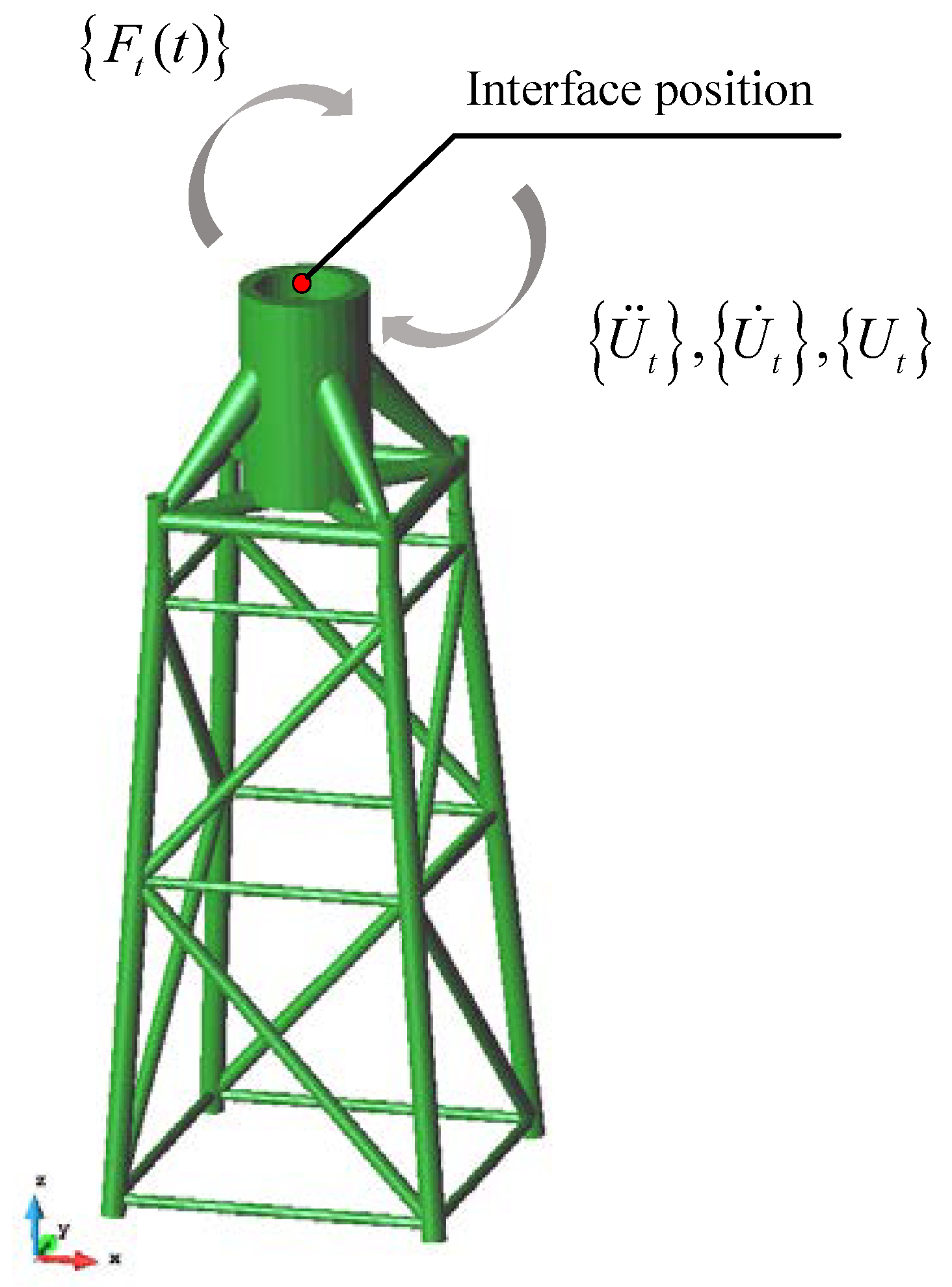
X-SEA finite element analysis software was developed for the design and analysis of onshore and offshore wind turbine platforms. The current version of X-SEA was developed at Konkuk University, Seoul, Korea [24]. The program has an extensive range of uncoupled and coupled analyses between the turbine and sub-structure using the FAST v8 program [15]. In each coupled analysis, the eighteen components of motions represented by the displacement { U t } , velocity { U ˙ t } , and acceleration { U ¨ t } vectors are input into the X-SEA program. Simultaneously, X-SEA returns the reaction force vector ( F t ( t ) ) at the interface position every analysis time t, as depicted in Figure 2. This “coupling” concept implemented and validated in the study [25] is expressed by:
[ M t ] { U ¨ t } + [ C t ] { U ˙ t } + [ K t ] { U t } = { F t ( t ) }
where M t , C t , and K t are the mass, damping, and stiffness matrices, respectively, of the coupled system at the time t.

3. Nonlinear Soil Springs

The API has developed a method for determining the pile capacity for lateral and axial bearing loads in either clay or sandy soils. All the information on pile load tests was derived in the laboratory from soil sample data. These datasets describe the lateral load deflection (P–Y), axial load displacement (T–Z), and tip load (Q–Z) at specific offshore sites [21]. The pile length is required to achieve tension (pullout) and compression capacities necessary to support the offshore wind turbine foundation. The soil around the pile must resist lateral and axial bearing loads, which correspond to skin friction and end bearing capacity, respectively. These should not exceed a certain limit under similar conditions with the same pile diameter and equipment used in the design.

3.1. Pile Lateral Loads

Pile foundations should be designed to sustain lateral loads, whether static or dynamic. A proper analysis of lateral loads in cohesive or cohesionless soils should use P–Y data, which are typically provided by geotechnical engineers. P–Y data describe the nonlinear relationship between lateral soil resistance and the depth of the piles [20]. For each layer of the soil along a pile depth, the P–Y data show a nonlinear relationship between the lateral pile displacement and lateral soil resistance per unit length. For static lateral loads, the ultimate unit lateral bearing capacity of soft clay has been found to vary between 8cs and 12cs, where cs is the undrained shear strength. In the absence of more definitive criteria, the following relationship is recommended by the API for soft clay:
P P u = 0.5 ( y y c ) 1 3
where P is the actual lateral resistance, P u is the ultimate resistance, y is the actual lateral deflection, and y c is the soil coefficient in terms of the pile diameter. In a more recent study, Jeanjean [26] showed that in conventional methods for assessing the lateral performance of conductors using the P–Y curves resulting from the API method, the soil springs might be too conservatively soft. That leads to the prediction of larger cyclic lateral displacements and bending stresses for a given load range than the P–Y curves obtained from centrifuge tests and finite element analysis. The latter is expressed as [26]:
P P u = tanh [ G max 100 . S u ( y D ) 0.5 ]
where G max is the shear modulus of the soil, S u is the undrained shear strength, y is the lateral displacement, and D is the pile diameter. The actual lateral load and ultimate lateral load relations can be obtained in terms of cumulative shear strain ( ξ ) as [26]:
P u = 12 4 e ( ξ d / D ) D S u
where
ξ = { 0.25 + 0.05 S u 0 d s u D 0.55 f o r f o r S u 0 d s u D < 6 S u 0 d s u D > 6
The above equations were applied to soft clay. The ultimate resistance ( P u ) for sand has been found to vary with the depth ( H ) of the soil layer, as described by [26]:
P u = { ( m 1 H + m 2 D ) γ H m 1 D γ H
Equation (5) gives the minimum value of the ultimate resistance, where m 1 , m 2 , and m 3 are the soil coefficients determined from the friction angle and γ is the soil density.

3.2. Pile Axial Loads and Tip Loads

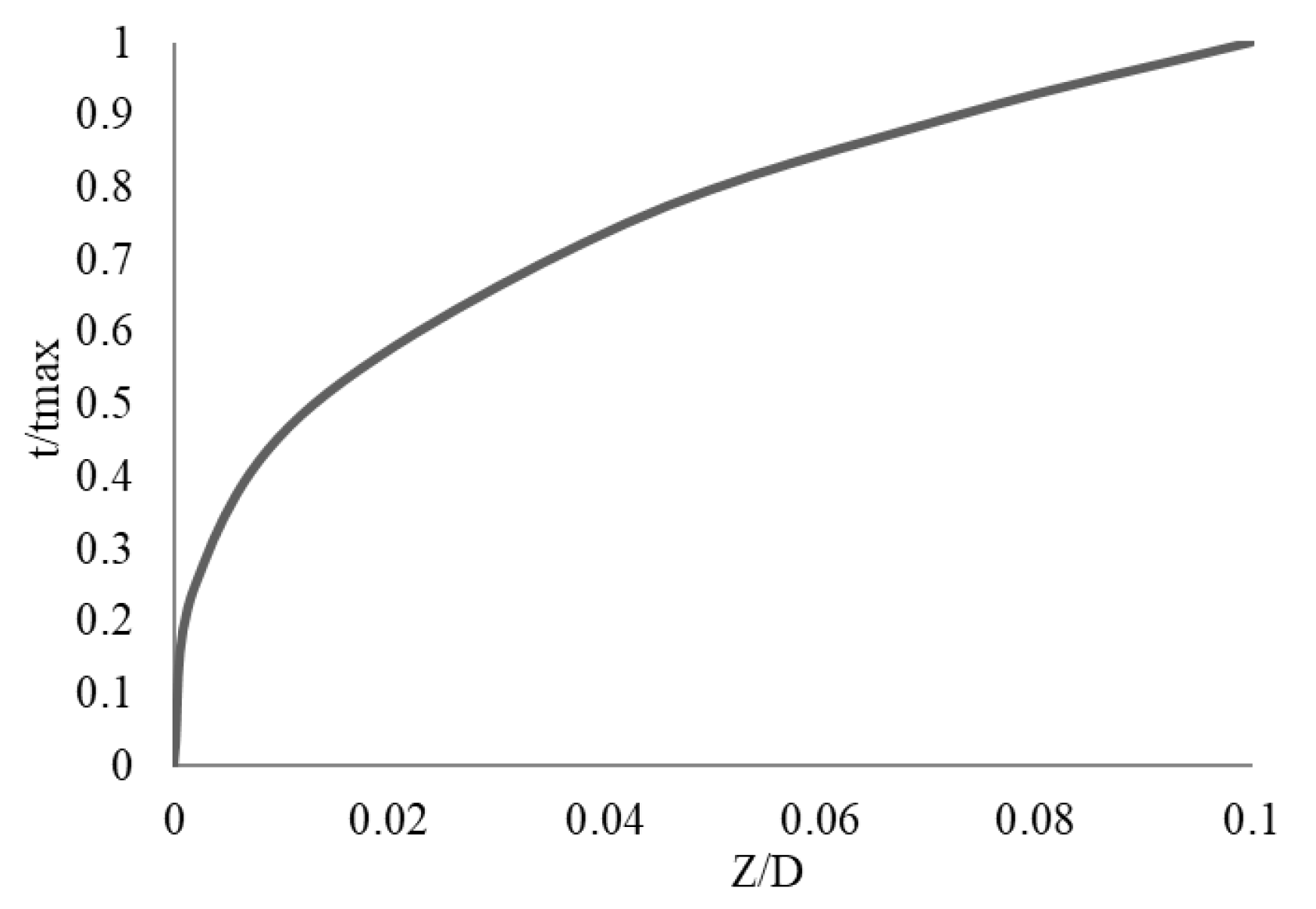
The axial resistance of the soil provides axial adhesion along the side of the pile. Several empirical relations and theories are available for producing curves for axial load transfers and pile displacements, or T–Z curves. Lymon and Michael [27] developed a load deflection relationship from a pile load test in representative soil profiles based on laboratory soil tests. The recommended curves are displayed in Figure 3 for cohesive soil. Similarly, the relationship between mobilized end bearing resistance and axial top deflection is described using a Q–Z curve [28], as shown in Figure 4.

3.3. Spring Stiffness

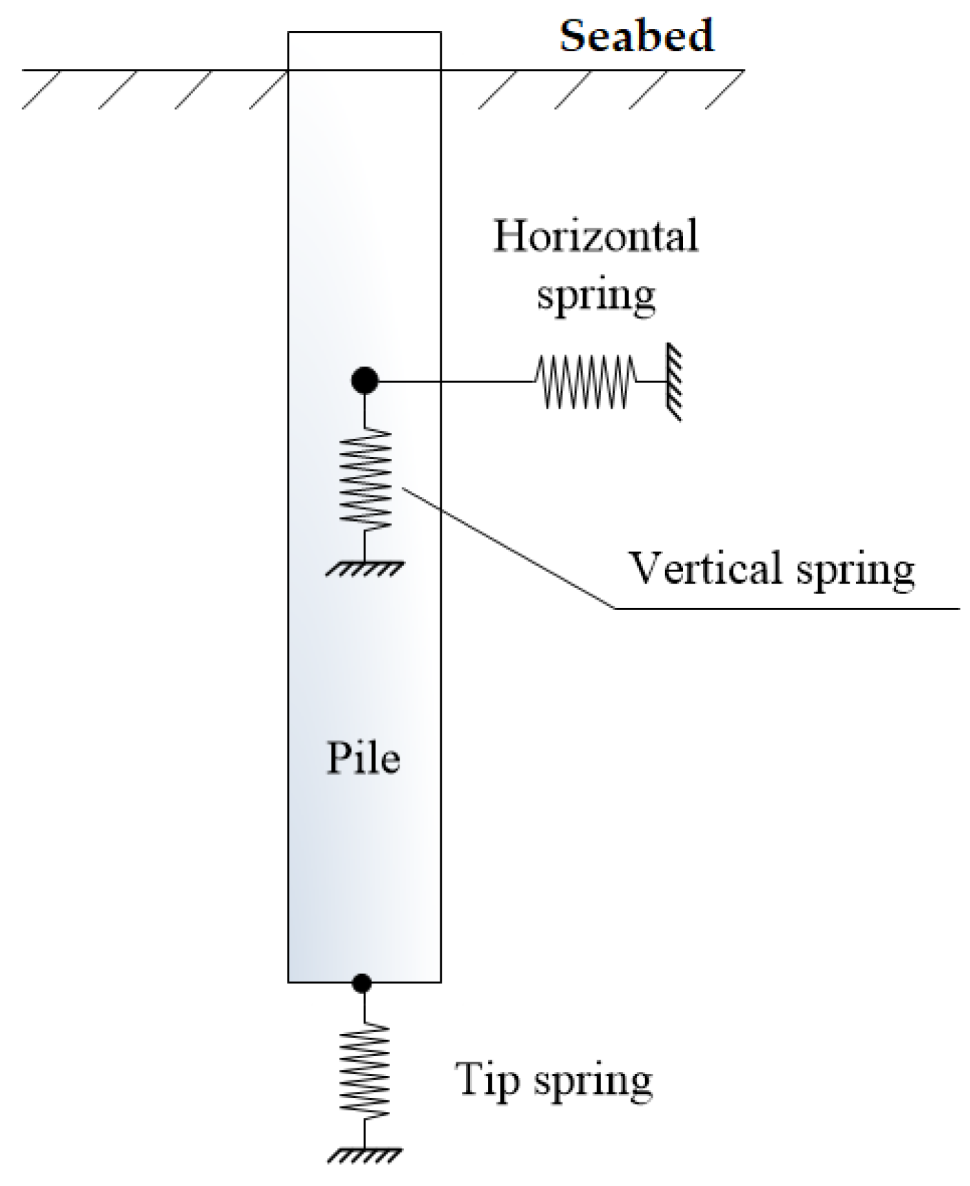
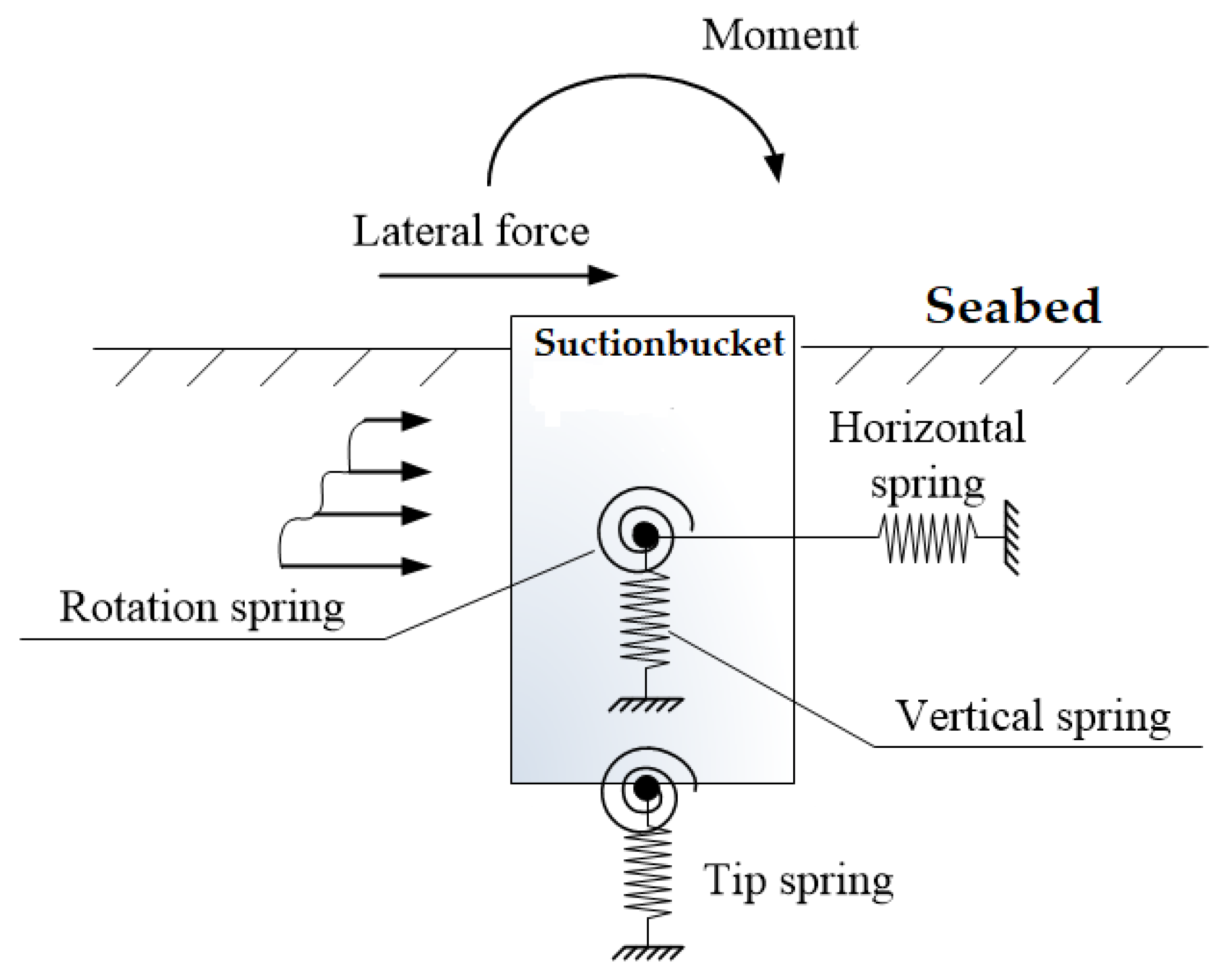
Structural engineering normally employs a constant spring stiffness for soil, which results in a linear force–displacement relation. However, as the nature of soil behavior is similar to plastic, this relation is not linear. Therefore, the interactions between the pile and the soil were modeled as a system of nonlinear springs, as illustrated in Figure 5. The information of P–Y, T–Z, and Q–Z was used in the present study to predict the stiffness of these nonlinear elastic springs applied along the pile length. However, in the model of the soil surrounding the pile with several translational springs, the whole system is subject to moments and acentric forces (see Figure 6). Consequently, its accuracy is not sufficient when using the API model [21] or Jeanjean’s method [26]. In this study, additional rotational springs were therefore proposed to be included in the model, where their rotational stiffness was determined by equating to tangent or secant modulus [29].

4. Pile–Soil Structure Interaction

Damiani and Wendt simulated the dynamic analysis of an offshore wind turbine on a fixed-bottom foundation while accounting for the super-element of the foundation and the piles [30]. This paper considered two methods for predicting the responses of suction bucket pile systems that can be used in offshore wind turbine foundations. The pile–soil interaction (PSI) method is a simulated behavior between the pile and soil. PSI analysis is highly essential for predicting the responses of a pile itself. However, this method does not consider the interactions between the pile and the super-structure at the time of analysis. The pile–soil–structure interaction (PSSI) method was designed for solving the interactions between the soil, the pile, and the structure [5]. This can be introduced into a global equation of motion,
[ M ] { U ¨ } + [ C ] { U ˙ } + [ K ] { U } = { F ( t ) }
where { F ( t ) } is the time-dependent force vector, [ M ] is the mass matrix describing the distribution of mass along the structure, [ C ] is the damping matrix that assumes 2% of critical damping [16], [ K ] is the stiffness matrix, and { u ˙ } and { u ¨ } are the first and second order derivatives of the displacement, respectively.
The global matrices can then be formed from the corresponding matrices of the tower (denoted by subscript ‘t’), the sub-structure (denoted by subscript ‘s’), and the pile (denoted by subscript ‘p’). Furthermore, PSSIs can be assembled into the global matrices for determining the deflection along the pile length, as presented in [6] and [25]. Thus, Equation (8) can be written as:
[ M t M s M p ] { U ¨ t U ¨ s U ¨ p } + [ C t C s C p ] { U ˙ t U ˙ s U ˙ p } + [ K t K s K p ] { U t U s U p } = { F ( t ) }
In reality, the movement of soil is difficult to predict, and figuring out a closed-form solution to such a problem is extremely complicated. In this study, a numerical solution for soil movement was therefore obtained by controlling the iterations and preventing the overshoot value for soil stiffness by using the utilized value N i :
N i = K i + 1 K i + 1
until N i converges closely to 1.0, at which, K i + 1 is the new stiffness at an iteration point and K i is the stiffness matrix at the previous iteration.

5. Wave Excitations and Hydrodynamics

5.1. Hydrodynamic Forces, Added Mass and Damping

The hydrodynamics of fixed offshore structures can be carried out by using hydrodynamic modules in the X-SEA program. The hydrodynamic forces, added mass, and damping and incident wave excitations are computed by using the Morison equation [25]. For a single element, the motion equation in terms of mass (m), damping (c), and stiffness (k) that is limited by the assumption of small dimension/wavelength ratio is:
( m + m ˜ ) w ¨ + ( c + c ˜ ) w ˙ + k w = 1 2 C d ρ A | v | v + C m ρ Δ v t
where ρ is a water density; C d and C m are drag and inertia coefficients, respectively; and v is the velocity of the water particle acting on the structural node and normal to the structure [25]. The term A is the cross-sectional area of the element, and Δ denotes the volume of the displaced fluid. The terms w ¨ , w ˙ , and w are the displacement, velocity, and acceleration, respectively, of the structure in its local coordinate, which are normal to or in its longitudinal axis. When the motion of the structure is considered, the inertia force is reduced by a factor proportional to the structural acceleration, and the drag force is reduced by the relative velocity and given in the form [25]:
m ˜ = ρ ( C m 1 ) Δ c ˜ = C d ρ A v ¯
in which v ¯ is the time-dependent cylinder velocity [25]. The terms in Equation (1) obtained in structure local coordinates are then transformed to the global coordinates. When the diameter (D) of the cross section in the structure is considerably larger than the wavelength (L), i.e., D / L 0.2 , the Morison theory is considered to be inapplicable and a diffraction theory implemented in X-SEA [31] can be considered.

5.2. Random Waves

The Pierson–Moskowitz (P–M) wave spectrum is an empirical relationship that defines the distribution of energy over frequencies within the ocean, and it has been found to fit ocean surface elevation measurements. It assumes that if the wind blows steadily for a long time over a large area, then the waves will eventually reach a point of equilibrium with the wind [32]. The international electrotechnical commission (IEC) announced that this spectrum model is best for using at specific site areas [33]. The parameters required for determining a wave spectrum are the significant wave height ( H s ) and the peak period ( T p ). The P–M spectrum can be written as:
S ( ω n ) = 0.04974 H s 2 T p c 5 e ( 1.25 c 4 )
where c = ω n T p 2 π . Based on the nonlinearity of wave characteristics, the statistical distribution of wave surface elevation ( η ) can be described by using the random phase angle ( ε n ), wave angular velocity ( ω n ), and wave number ( k n ) [34] as:
η = Σ n A n sin ( ω n t k n x + ε n )
in which A n is a wave amplitude corresponding to each set of wave height, frequency, and phase angle. The wave amplitude can be expressed by using the P–M spectrum in Equation (11) in terms of the angular velocity interval ( Δ ω ) as:
A n = 2 S n Δ ω
For each state of wave surface elevation, the associated horizontal velocity and acceleration of the water particles are determined from the basic wave theory [35]. Assuming an one-dimension sea where all waves are running in the same direction, the horizontal water velocity ( u ) and acceleration ( a ) in the direction of wave propagation are given at an elevation ( z ) by the equations:
u = Σ n A n ω n cosh ( k n z ) sinh ( k n d ) cos ( k n x ω n t + ε n ) a = Σ n A n ω n 2 cosh ( k n z ) sinh ( k n d ) sin ( k n x ω n t + ε n )

6. Numerical Study

6.1. Verification of Soil–Pile Interactions

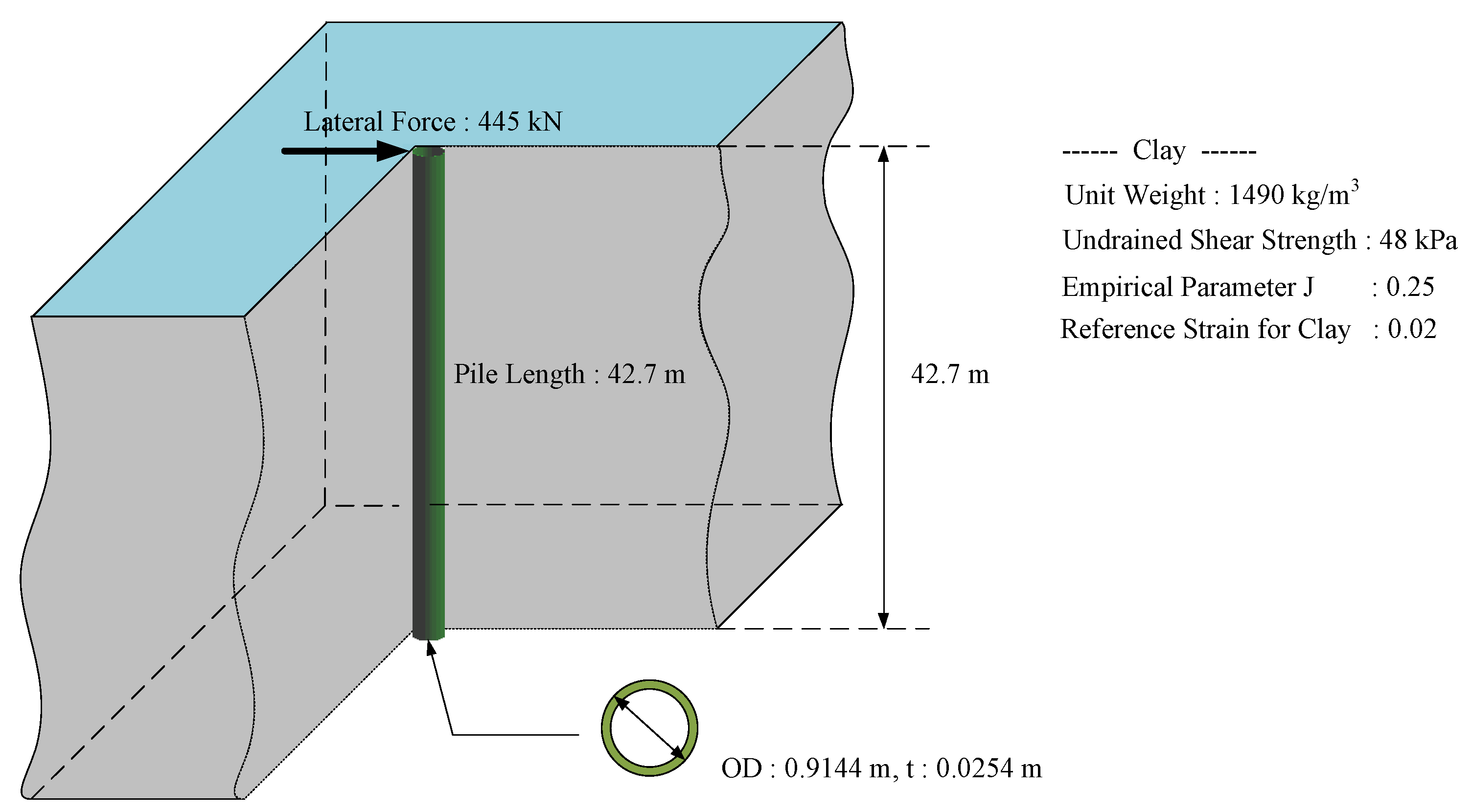
A single pile that had been driven 42.7 m into a single soft clay layer was considered. A numerical model of this case using 11 nodes and 10 elements per layer is shown with the soil properties in Figure 7. The simulation of the pile foundation involved a lateral load of 445 kN. The nonlinear behavior for the pile–soil interactions was based on the geotechnical P–Y data from the API [21] and Jeanjean methods [26]. This can be considered as loads corresponding to the lateral deflection along the pile. A commercial package called “Structural Analysis Computer System” (SACS) [36] was used to perform the analysis.
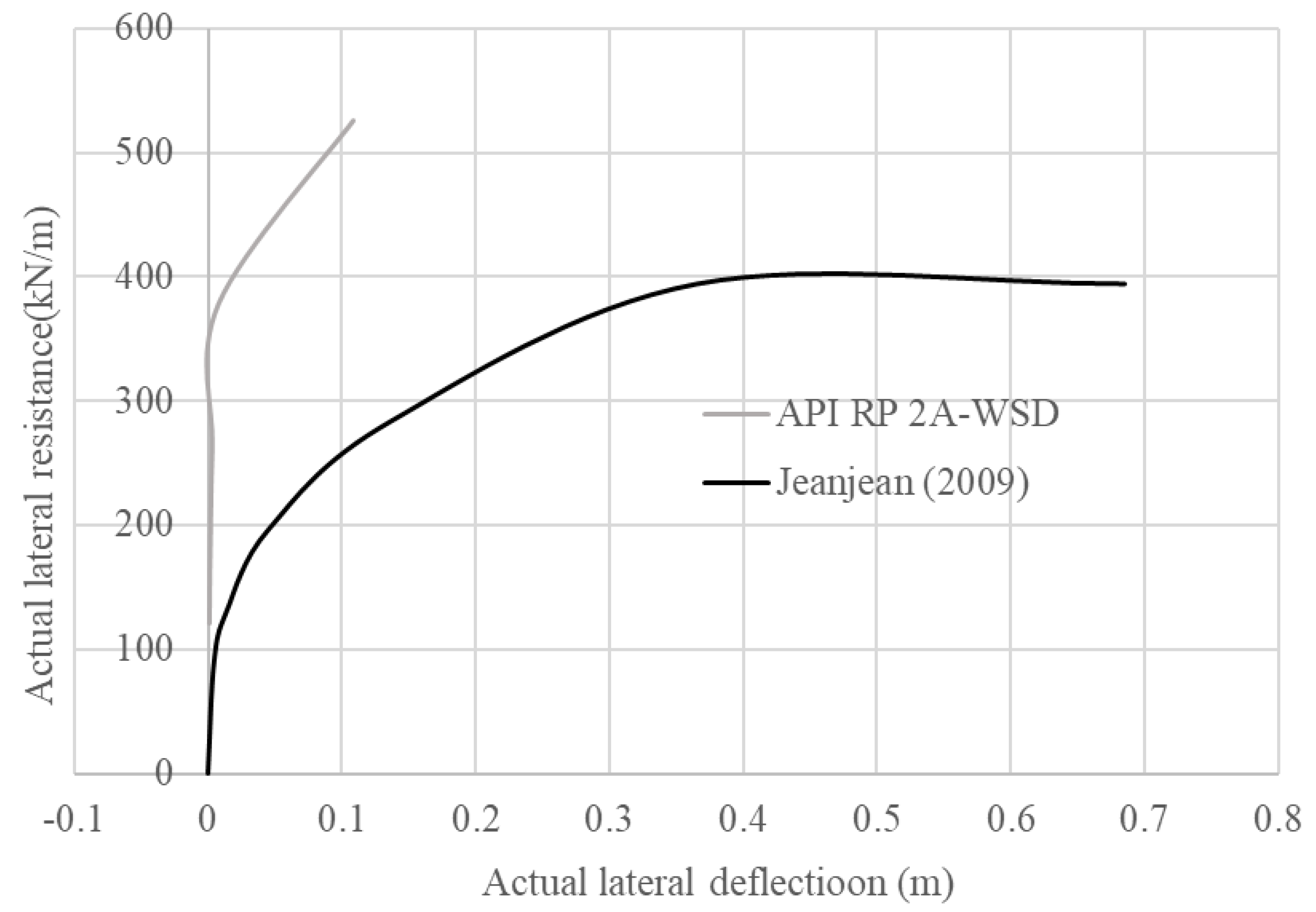
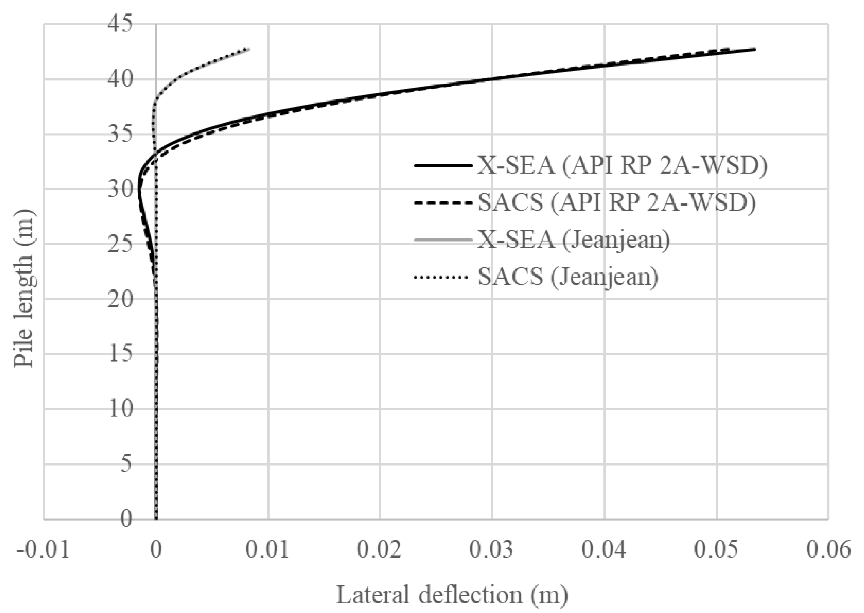
The loads corresponding to the P–Y deflection curve were simulated during the iterative process of the X-SEA program. This was used to obtain soil stiffness and to input additional stiffness into the structure. The resulting loads corresponding to the deflection are plotted in Figure 8, which indicates that the maximum lateral resistance using Jeanjean’s data was 1.33 times more than that found when using the API data. Moreover, Figure 9 shows that the lateral deflections resulting from the X-SEA and SACS programs by using the API method were in good agreement. The deflections resulting from both programs when using the Jeanjean method also agreed well with each other, as seen in Figure 9. These agreements validated the implementation of the API and Jeanjean methods and the nonlinear springs in X-SEA, which were used for further analyses in this paper.

6.2. Coupled Dynamic Analysis of Turbine and Support Structure with Pile–Soil–Structure Interaction (PSSI)

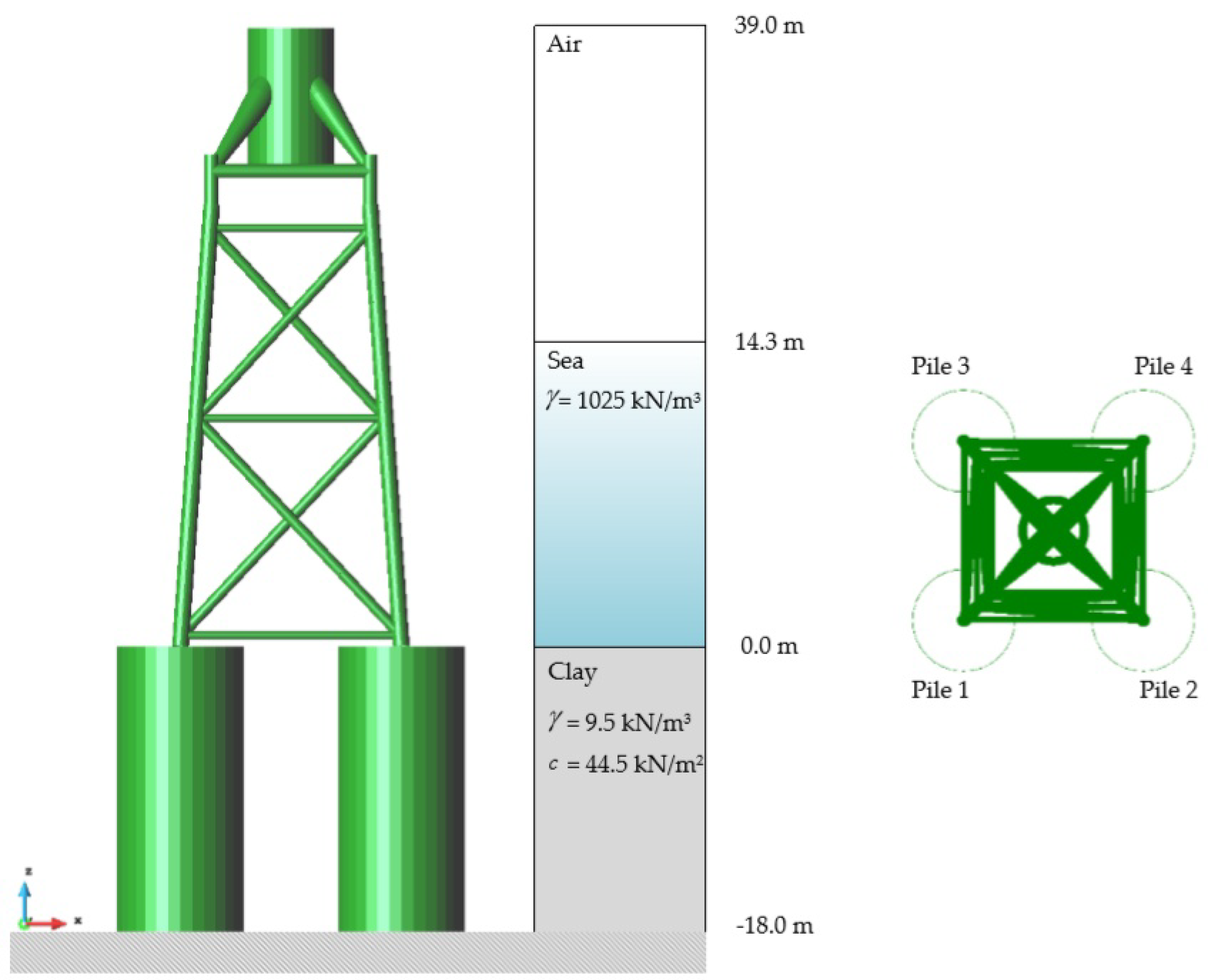
In this example, a 5 MW offshore wind turbine [37] jacket foundation system [38] was simulated. The significant wave height (Hs) was 3.3 m, and the wave period (Tp) was 8.0 s. A constant current velocity of 1.2 m/s and mean wind speed of 13.156 m/s at the Buan country site in South Korea were considered. The turbulent wind simulator (TurbSim) program [39] was used to generate a stochastic of wind velocity model based on the IEC standard [33], as illustrated in Figure 10. The simulation was carried out using the wind velocity in time domain that is required in FAST v8, as illustrated in Figure 10. A marine growth 0.1 m thick with a weight density of 1100 kg/m3 was used in this example to represent the actual size and weight of the jacket structure along water depth. The foundation was connected with four circular tube suction piles, each 8 m in diameter and 0.05 m thick, and embedded in a single layer soil at a depth of 18 m. A frame element model was validated [40] and used to investigate the behavior of the suction bucket pile through the pile length without considering the super-element, as illustrated in Figure 11. The piles-supported foundation was modeled, and the effects of the soil behavior using the API and Jeanjean methods were compared; this formed an approach for determining the pile capacity for lateral loads in soft clay. The horizontal stiffness and end bearing in either soil were used in accordance with API recommendations. A coupled dynamic analysis module was connected to the PSSI program, which considered the interactions among the pile, soil, and foundation to determine the behavior of the whole system as a function of time. The analysis period was selected as the first 200 s, which included both transient and steady responses. The geometric and material properties of the jacket foundation are given in Table 1. Seismic excitations [41] were not accounted for, but they should be considered in future analysis and design.
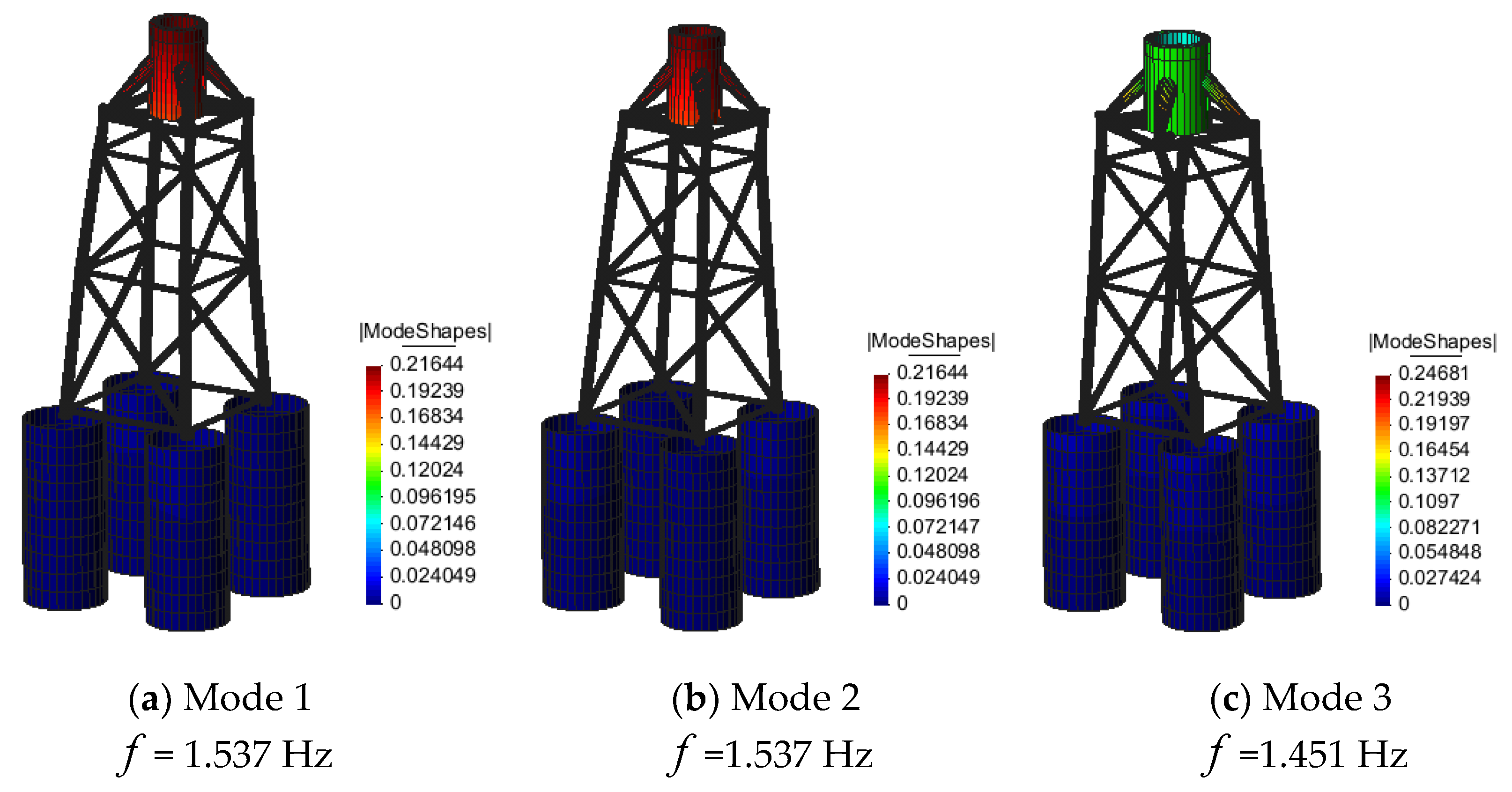
The asymmetrical loads caused the structure to resonate due to the environmental loads and the fact that the natural frequencies of the system were close to those of the turbine blades. In order to avoid resonance, a free vibration analysis of the suction pile foundation with fixed boundary conditions was first carried out using the X-SEA program. The natural frequencies—those related to the type of boundary condition—were compared, and the three mode shapes were modeled, as shown in Figure 12. A scale factor of 10–15 was used to amplify the mode shapes of the jacket foundation. The first mode shape was a bending mode of the whole structure with a 1.537 Hz natural frequency, as illustrated in Figure 12a, where the suction pile with fixed boundary condition is oscillating globally in the x-direction. The second mode shape was the same as the first mode but oscillating in y-direction, as illustrated in Figure 12b. The third mode shape was a torsional mode about the z-axis with the natural frequency of 1.451 Hz, where twisting was occurring from the free end to the fixed boundary, as illustrated in Figure 12c.
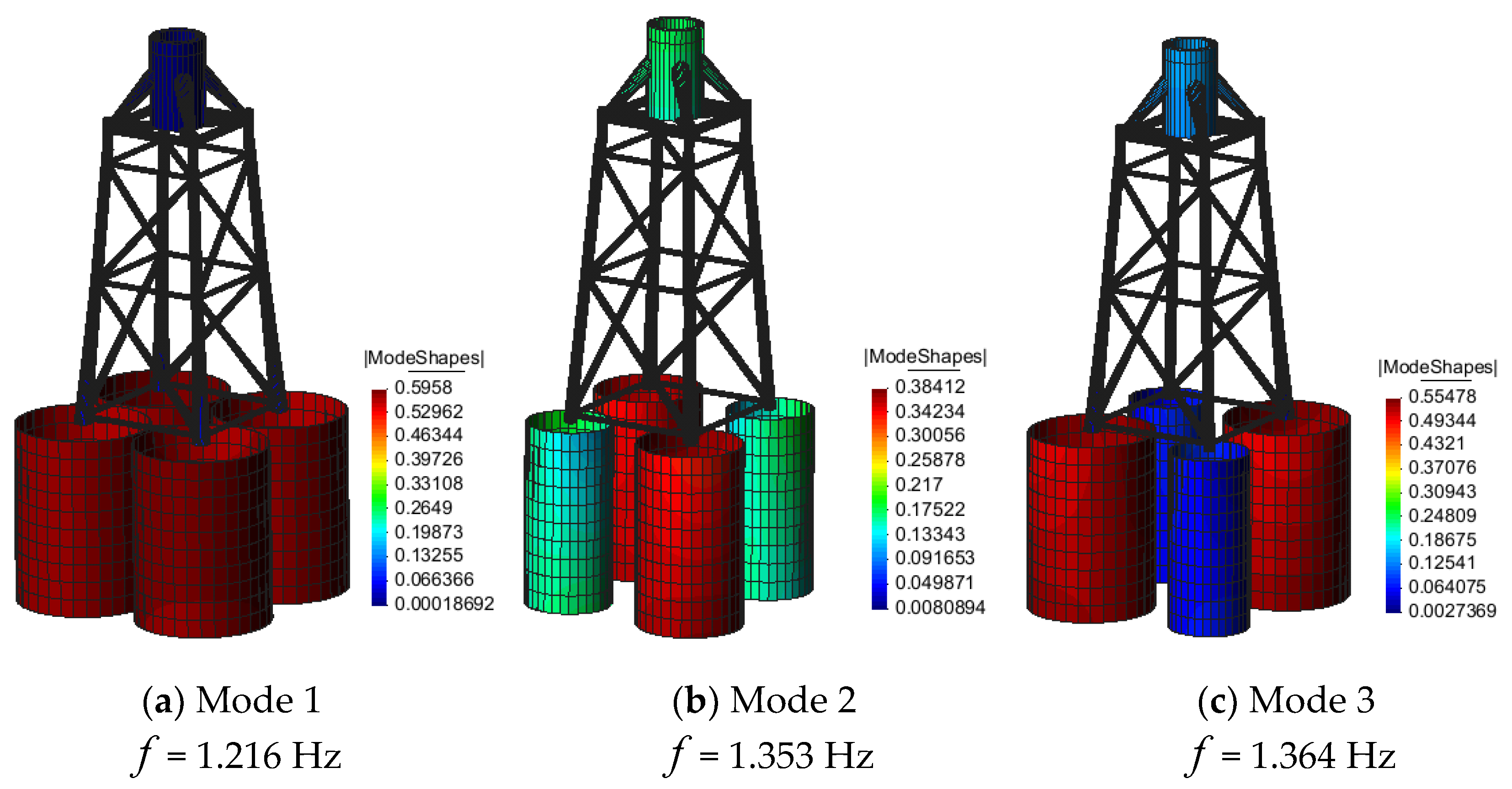
In the second free vibration analysis, the soil spring stiffness determined from P–Y, T–Z, and Q–Z curves were applied along the pile length and modelled by using both the API and Jeanjean methods. The first mode shape of the suction piles with the API method was the movement in x-direction with a natural frequency of 1.087 Hz, as illustrated in Figure 13a. In the second and third modes, the natural frequencies were 1.213 and 1.357 Hz, respectively. The twisting occurred at the suction bucket piles and caused the different shape size of the pile. Meanwhile, the first to the third mode shapes using the Jeanjean method were all twisting, as shown in Figure 14a–c. By comparing the natural frequencies resulting from soil stiffness models by using the API and Jeanjean methods, it could be seen that natural frequencies resulting from Jeanjean’s method were, respectively, 1.118, 1.115, and 1.005 higher than those from the API method for the first to the third modes. It was obvious that the pile with fixed boundary conditions was stiffer than the spring model, and it had less inertia. Hence, the natural frequencies corresponding to the fixed boundary condition were higher than those of the spring models determined from the P–Y, T–Z, and Q–Z curves.
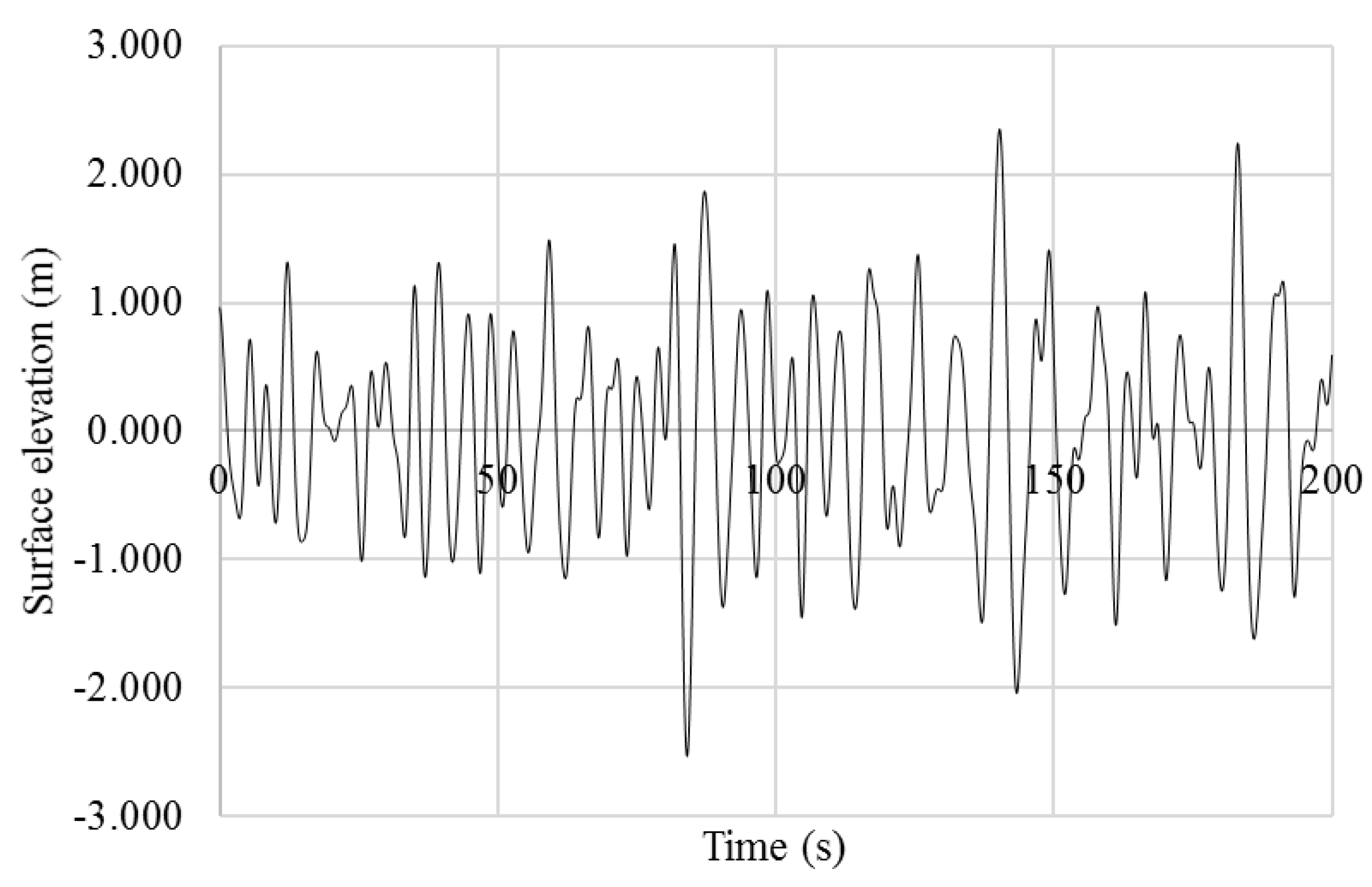
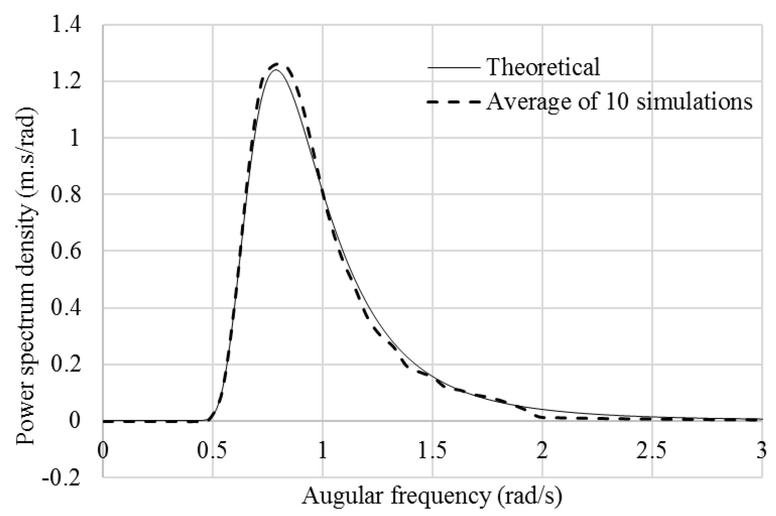
In the forced vibration analysis, random waves were simulated by using Equations (12)–(15); a wave surface elevation profile is shown in Figure 15. The angular velocity interval ( Δ ω ) was assumed to be at 0.01 rad/s, and the time interval was 0.1 s, which was sufficiently small compared to the wave period and structural vibration periods. In order to validate the random wave simulations, the fast Fourier transform (FFT) was used to transform time series to frequency domain [42], and 10 realizations of wave surface elevation profiles were used. The averaged power spectrum density of the wave elevation simulations was in good agreement with the theoretical spectrum, as shown in Figure 16.
In the iterative process of the forced vibration analysis, the lateral and horizontal displacements were received at the interface and transferred through the spring supports. These motion components were used to generate the P–Y, T–Z, and Q–Z curves and applied to calculate the stiffness of the springs. At the same time, six reaction components were fed back to the tower and turbine. The iteration continued until all of the components converged. In order to avoid diverging with asymmetrical loads, the rotational stiffness was applied, whereas frame elements were used to model the jacket and the jacket foundation resisted for a moment. This did not influence the P–Y, T–Z, and Q–Z curves used in the API and Jeanjean methods.
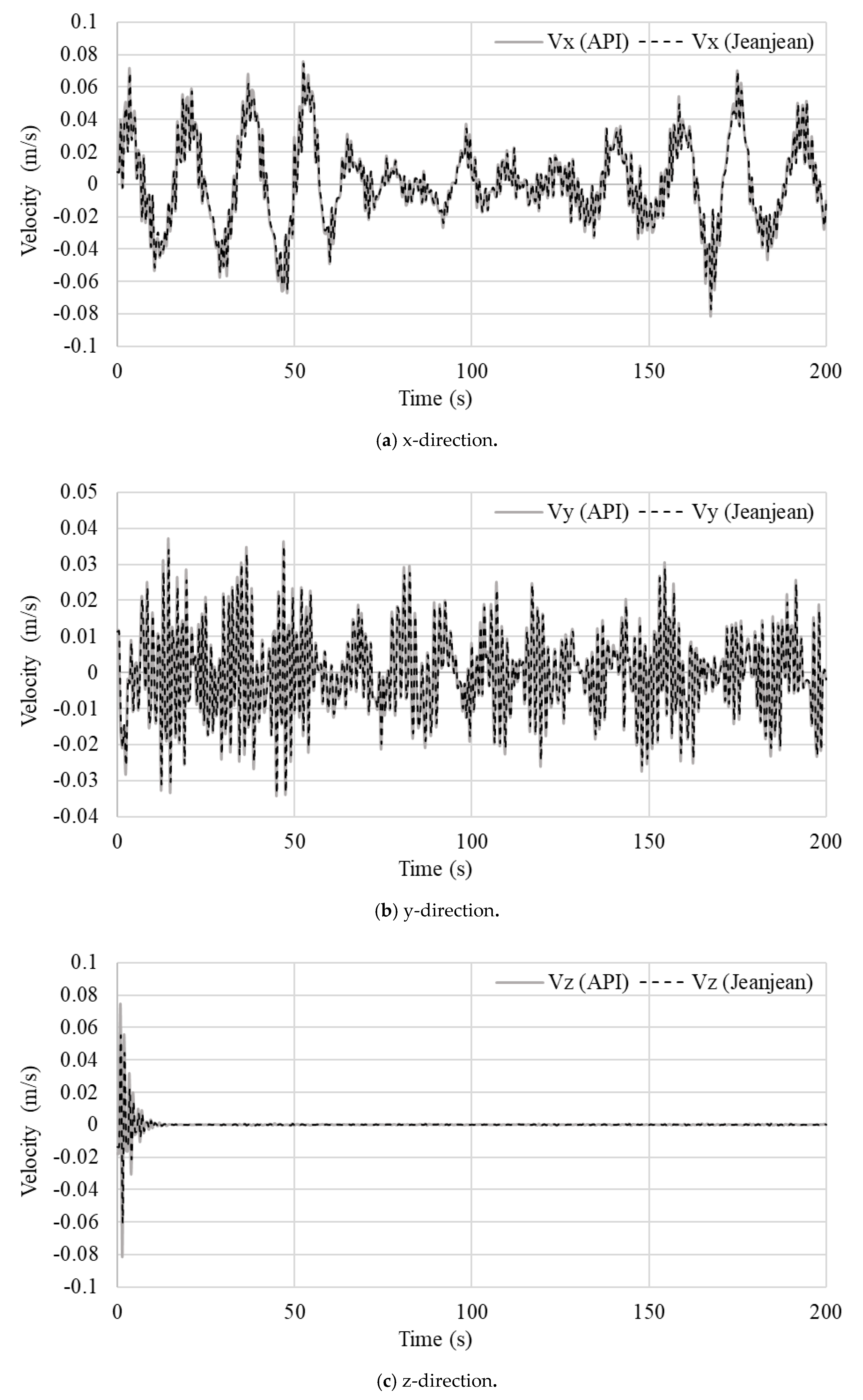
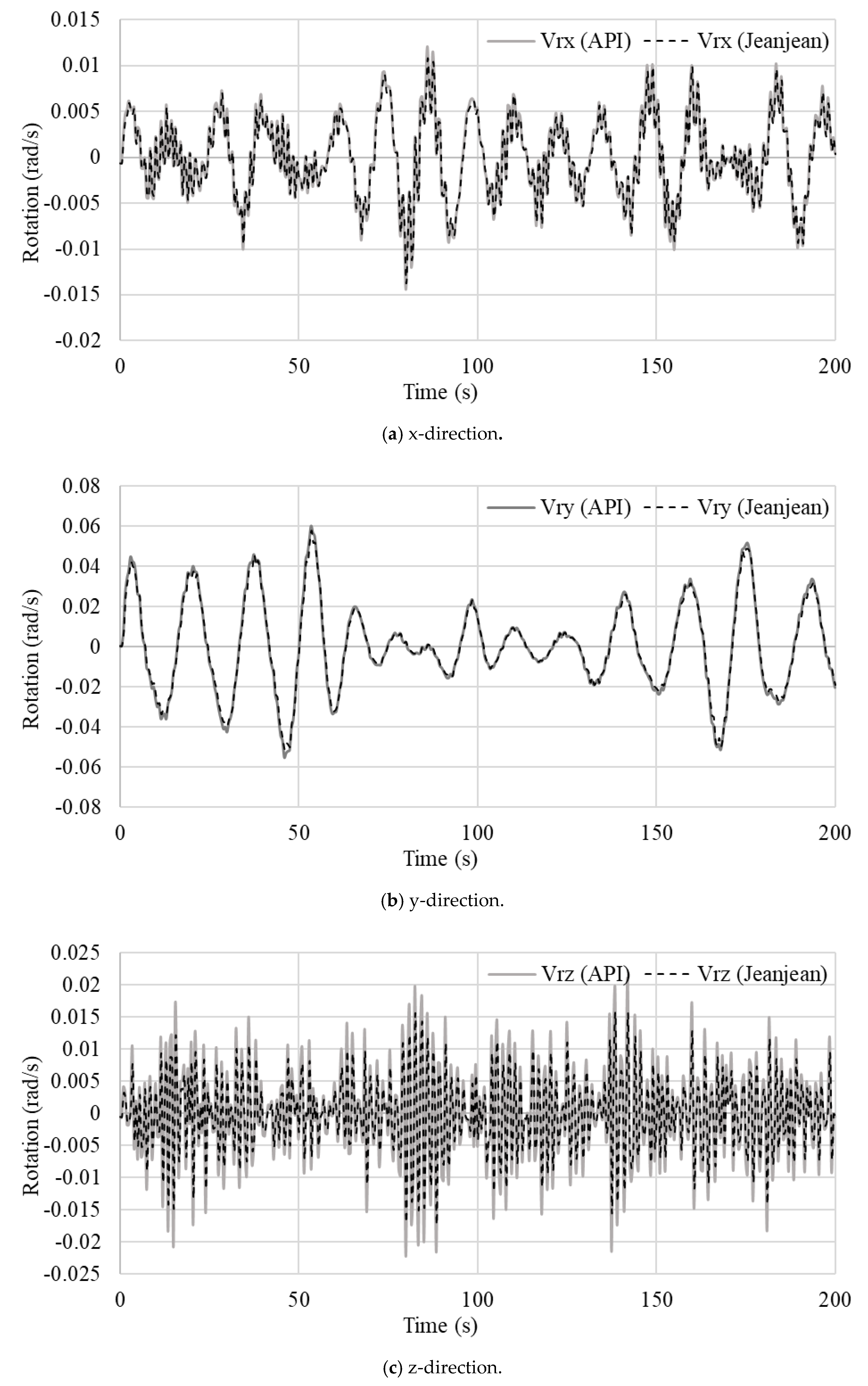
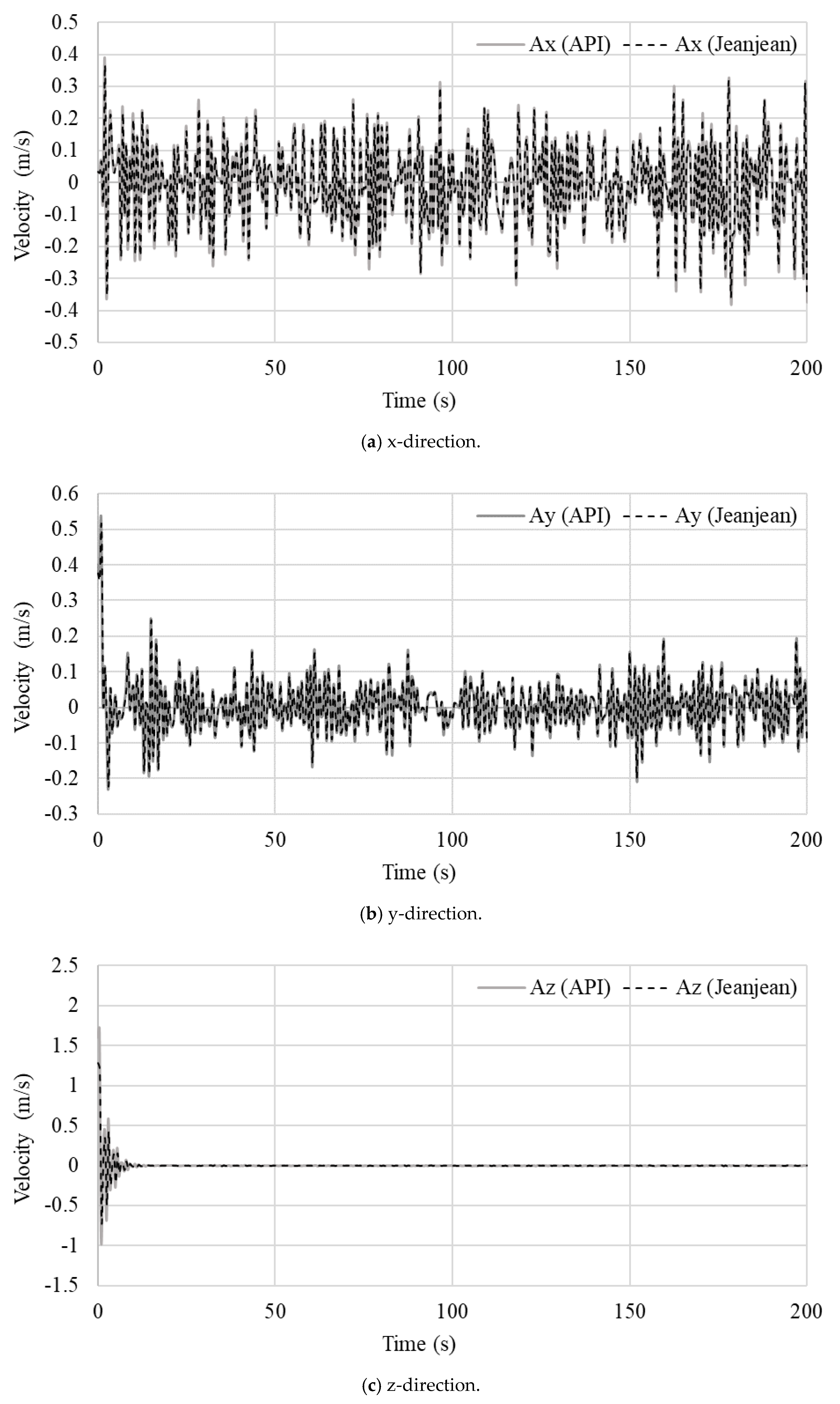
The resulting time histories of the translation velocity ( V ), rotational velocity ( V r ), acceleration ( A ), rotational acceleration ( A r ), and rotational displacement ( U r ) at the interface in the x-, y-, and z-directions in equation of motion, as described in Equation (8), are shown in Figure 17, Figure 18, Figure 19, Figure 20 and Figure 21. The averaged displacements, velocities, and accelerations in Table 2 show that the API method made the foundation model more flexible than Jeanjean’s method.
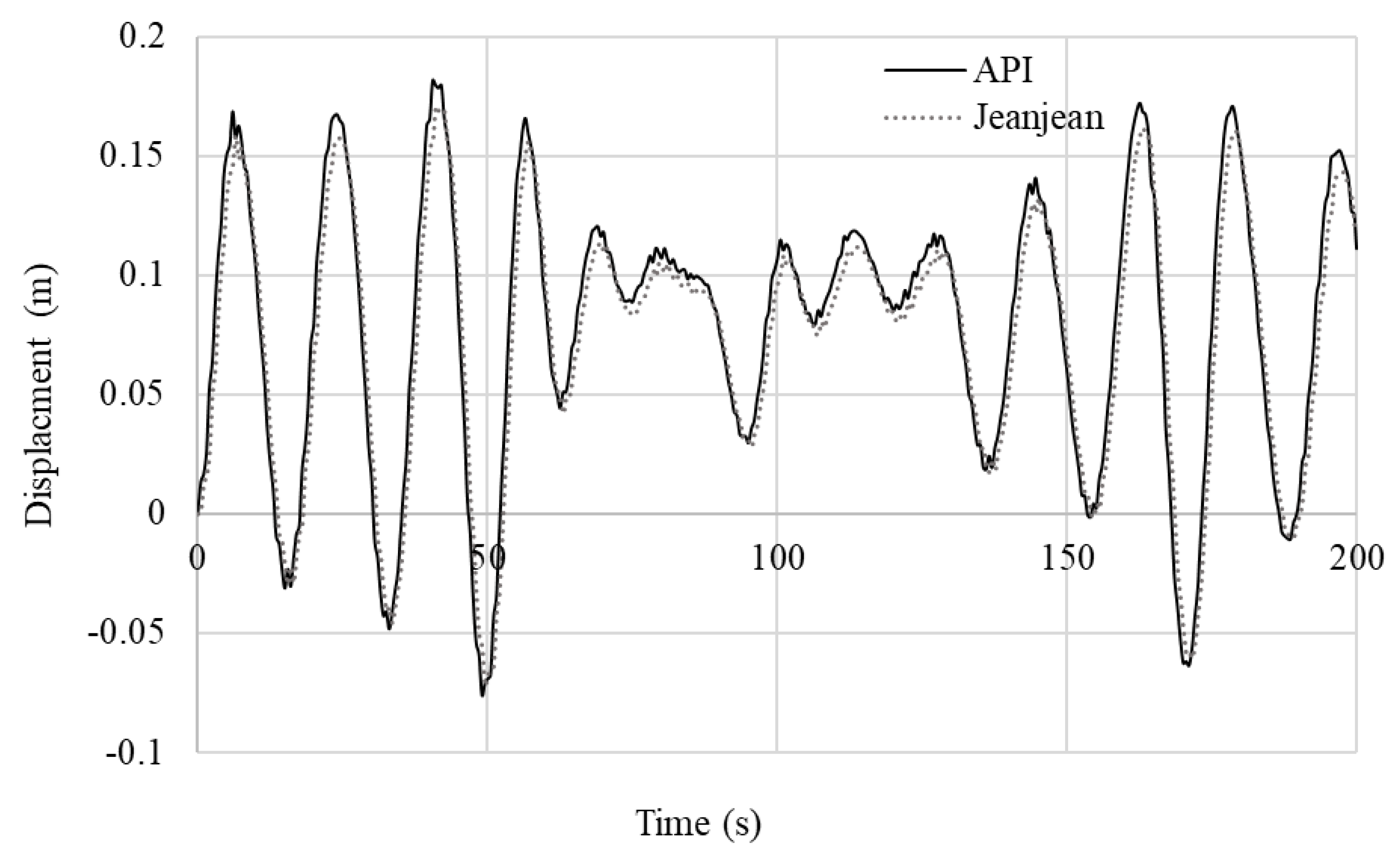
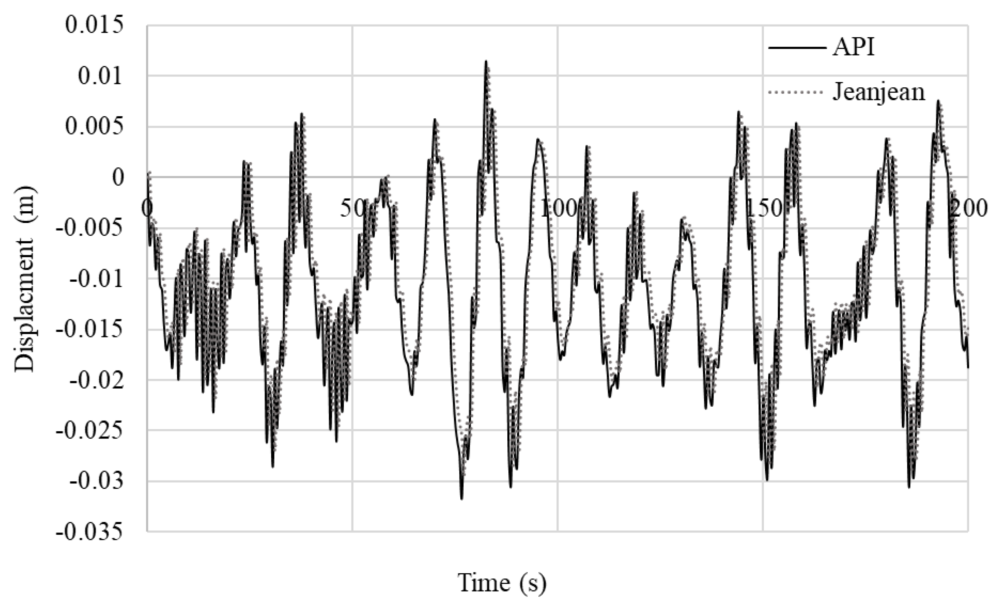
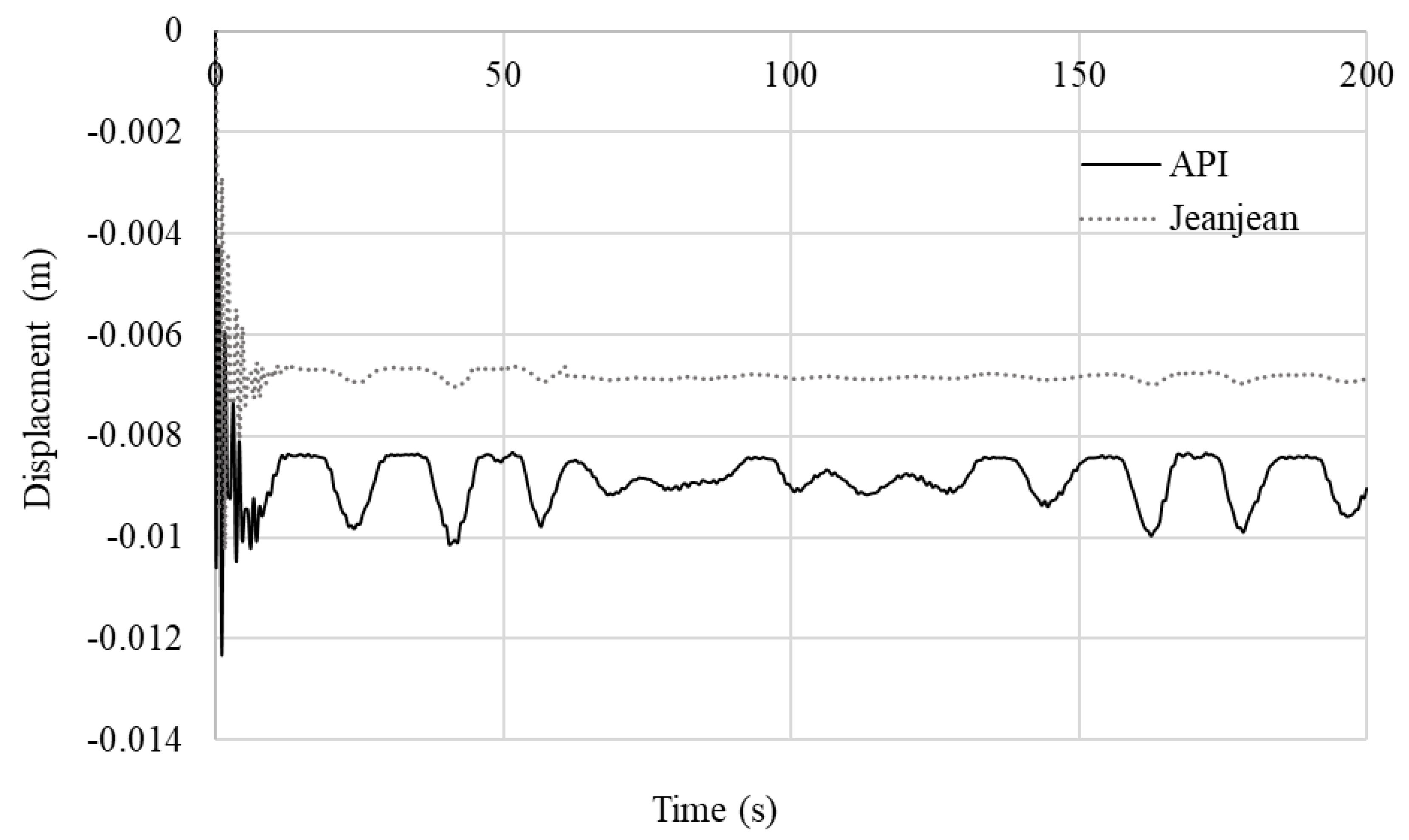
Comparing the displacement of the jacket foundation in Figure 22 shows that the API method led to more flexible responses than Jeanjean’s method by an average factor of 1.062 in the x-direction. As the lateral stiffness of a single point affected the horizontal stiffness of other points along the pile depth, it caused different responses in the y- directions and z-directions by factors of 1.069 and 1.303, respectively, as illustrated in Figure 23 and Figure 24. The results in Figure 24 show high vertical responses at starting up times. In order to compare the difference between two soil modelling methods, the average percentage results are presented in Figure 25. The responses of the jacket foundation were seen to be significantly influenced by the environmental loads, turbine responses, structural stiffness, and the type of nonlinear three-dimensional soil spring stiffness.
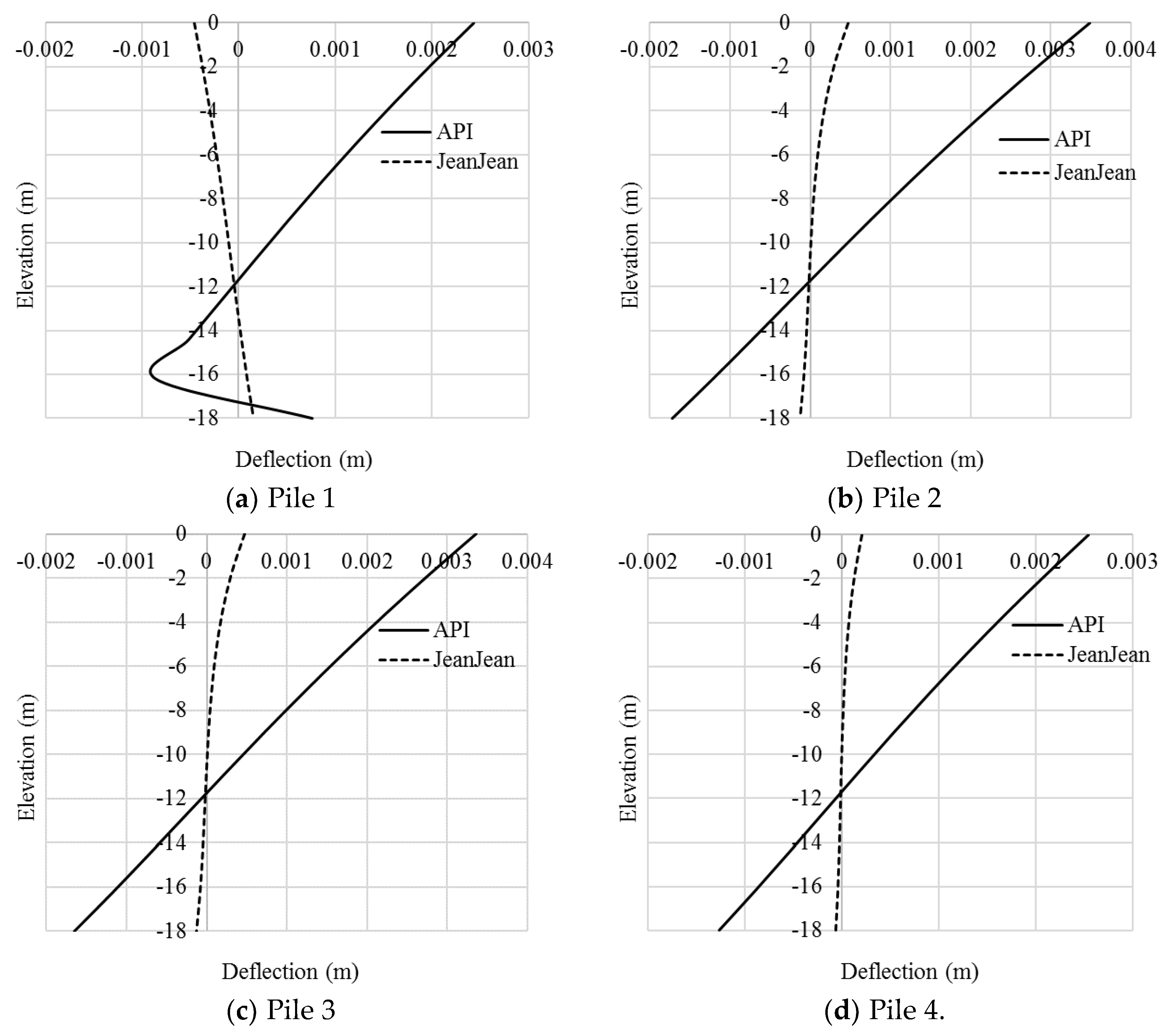
During the period in which the loads were acting on the foundation, the structure should be against and sustaining the loads. They were transferred through to the pile, corresponding to the end bearing and soil skin friction. These produced a distribution of deflection along the pile length. The responses of the pile heads in the four piles resulting from the API method were more flexible than those resulting from Jeanjean’s method by factors of 5.300, 7.330, 7.0290, and 12.158 times, as shown in Figure 26. Eventually, the total computational time on a dual CPU (Intel i7-7820HQ 2.9 GHz-8 cores) was 72.03 h for coupled analysis with PSSIs and 5.06 h without considering PSSIs.

7. Conclusions

A theoretical background of the coupled dynamic analysis of offshore wind turbine and support structures implemented and validated in the authors’ previous publications was improved by including PSSIs and suction bucket pile models. Approaches to computing soil lateral, axial, and tip resistances were provided by considering the P–Y, T–Z, and Q–Z curves of soil behavior obtained by either the API or Jeanjean methods. The loads corresponding to these curves could be simulated by an iterative process of the X-SEA program. Such soil resistances were represented by nonlinear springs in the lateral and vertical directions along the piles. In order to more accurately simulate the suction bucket piles subject to acentric forces and moments, rotational springs were added to the models, where their rotational stiffness was determined by equating to the tangent or secant modulus obtained from Jeanjean’s method.
The implementation of the improved PSSI models using soil springs and the API and Jeanjean methods in the X-SEA program was verified in an example of a laterally loaded single pile driven 42.7 m into a soft clay soil. The soil spring stiffness values were based on the P–Y data obtained from both methods. The PSSI modelling and analysis were performed in both the X-SEA and SACS programs. The maximum lateral resistance resulting from Jeanjean’s method was 1.33 times larger than from the API. The lateral deflections resulting from X-SEA and SACS are in good agreement with each other when using either the API or Jeanjean methods.
In order to study the behavior of suction bucket piles and offshore wind turbine–jacket–pile systems, a five MW offshore wind turbine in the Buan country site in Korea was examined in X-SEA coupled with FAST. Random wind and waves with a significant height of 3.3 m, a period of 8.0 s, a current velocity of 1.2 m/s, a mean wind speed of 13.156 m/s, and a marine growth of 0.1 m thick with a weight density of 1100 kg/m3 were considered. The four suction bucket files penetrated into a single clay lay of 18 m thick. Free vibration and coupled dynamic analyses of the system were performed, and the following conclusions were drawn:
1)
In the free vibration analysis with fixed boundary conditions (rigid soil), the first and second modes were globally bending and of the same natural frequencies, where the piles oscillated in two horizontal axes. The third mode was torsional about the vertical axis.
2)
In the free vibration analysis with the soil spring stiffness determined from P–Y, T–Z, and Q–Z curves using the API method, the suction piles were of lateral movement in the first mode with a distinctly lower natural frequency, and they were twisting in their second and third modes, whereas the first to the third modes of the suction piles using Jeanjean’s method were all twisting. The natural frequencies of the first to the third modes resulting from Jeanjean’s method were higher than those from the API method.
3)
In the forced vibration analysis, the API method made the foundation model more flexible than that of Jeanjean’s method, particularly the pile head. The jacket foundation responses were seen to be significantly influenced by the environmental loads, turbine responses, structural stiffness, and the type of nonlinear soil spring stiffness. The coupled analysis with PSSIs was quite computationally expensive.
Scour effects, soil damping models, and seismic excitations are recommended to be considered in future research for the further understanding of the system behaviors.

Author Contributions

Formal analysis, P.P.; investigation, P.P. and V.N.D.; validation, P.P.; conceptualization, P.P., O.K., V.N.D., and K.-D.K.; methodology, V.N.D., J.M., and K.-D.K.; writing—original draft preparation, P.P. and V.N.D.; writing—review and editing, V.N.D., J.M., and K.-D.K.; funding acquisition, K.-D.K. All authors have read and agreed to the published version of the manuscript.

Funding

This work is supported by Korea Electric Power Corporation (Development of analysis program of offshore wind turbine structure and design example using FAST turbine aerodynamic load), Korea. This work was supported by KEPCO(2017), Korea. The third author (V.N.Dinh) and the fourth author (J.Murphy) have been supported by the Science Foundation Ireland (SFI) MaREI Centre, the Sustainable Energy Authority of Ireland under the SEAI RS&D Funding Programme 2019 (Grant number 19/RDD/545), and the VeriX-SEA project. The authors are grateful for the support.

Conflicts of Interest

The authors declare no conflict of interest.

References

  1. Zhang, J.; Sun, K.; Wang, Z.; Zhang, L. Static and Dynamic Analysis of Monopile Foundation for Offshore Wind Farm. In Proceedings of the International Offshore and Polar Engineering Conference, Beijing, China, 20–25 June 2010. [Google Scholar]
  2. Scharff, R.; Siems, M. Monopile foundations for offshore wind turbines—Solutions for greater water depths. Steel Constr. 2013, 6, 47–53. [Google Scholar] [CrossRef]
  3. De, C.; Kai, H.; Lijun, H. Comparison of Structural Properties between Monopile and Tripod Offshore Wind-Turbine Support Structure. Adv. Mech. Eng. 2013, 2013, 1756849. [Google Scholar]
  4. Georgia, M.; Anastasios, P.; Dimosthenis, B.; Charis, J.G.; Christos, P.G. Design of Monopile and Tripod Foundation of Fixed Offshore Wind Turbine via Advanced Numerical Analysis. In Proceedings of the 8th GRACM International Congress on Computation Mechanics, Volos, Greek, 12–15 July 2015. [Google Scholar]
  5. Schaumann, P.; Böker, C. Can jackets and tripods compete with monopiles? In Proceedings of the Copenhagen Offshore Wind, Copenhagen, Denmark, 26–28 October 2005.
  6. Plodpradit, P.; Dinh, V.N.; Kim, K.-D. Coupled Analysis of Offshore Wind Turbine Jacket Structures with Pile-Soil-Structure Interaction Using FAST v8 and X-SEA. Appl. Sci. 2019, 9, 1633. [Google Scholar] [CrossRef] [Green Version]
  7. Wei, S.; Chinwha, C. Comparison of Dynamic Response of Monopile, Tripod and Jacket Foundation System for a 5-MW Wind Turbine. In Proceedings of the 21st International Offshore and Polar Engineering Conference, Maui, HI, USA, 19–24 June 2011. [Google Scholar]
  8. Wei, S.; Park, H.C.; Han, J.H.; Na, S.K.; Kim, C.W. A Study on the Effect of Different Modeling Parameters on the Dynamic Response of a Jacket-Type Offshore Wind Turbine in the Korean Southwest Sea. Renew. Energy 2013, 58, 50–59. [Google Scholar]
  9. Ingrif, B.L.; Amir, M.K. Effect of Foundation Type and Modelling on Dynamic Response and Fatigue of offshore wind turbine. Wind Energy 2012, 22, 12. [Google Scholar]
  10. Wu, Y.; Li, D.; Zhang, Y.; Chen, F. Determination of Maximum Penetration Depth of Suction Caissons in Sand. KSCE J. Civ. Eng. 2017, 22, 2776–2783. [Google Scholar] [CrossRef]
  11. Wang, X.; Yang, X.; Zeng, X. Lateral response of improved suction bucket foundation for offshore wind turbine in centrifuge modelling. Ocean Eng. 2017, 141, 295–307. [Google Scholar] [CrossRef]
  12. Tasan, H.E.; Yilmaz, S.A. Effects of installation on the cyclic axial behaviour of suction buckets in sandy soils. Appl. Ocean Res. 2019, 91, 101905. [Google Scholar] [CrossRef]
  13. Latini, C.; Zania, V. Dynamic lateral response of suction caissons. Soil Dyn. Earthq. Eng. 2017, 100, 59–71. [Google Scholar] [CrossRef] [Green Version]
  14. Mohammadm, A.; Saif, H. Optimized frequency-based foundation design for wind turbine towers utilizing soil-structure interaction. J. Frankl. Inst. 2010, 348, 1470–1487. [Google Scholar]
  15. Jonkman, J. FAST v8. National Renewable Energy Laboratory (NREL): Golden, CO, USA, 2018. Available online: https://nwtc.nrel.gov/FAST8 (accessed on 19 September 2017).
  16. Chen Ong, M.; Bachynski, E.E.; David Økland, O. Dynamic Responses of Jacket-Type Offshore Wind Turbines Using Decoupled and Coupled Models. ASME J. Offshore Mech. Arct. Eng. 2017, 139, 041901. [Google Scholar] [CrossRef]
  17. Bin, Z.; De-qiong, K.; Ren-peng, C.; Ling-gang, K.; Yun-min, C. Installation and lateral loading tests of suction caissons in silt. Can. Geotech. J. 2011, 48, 1070–1084. [Google Scholar]
  18. Wang, P.; Zhao, M.; Du, X.; Liu, J.; Xu, C. Wind, wave and earthquake responses of offshore wind turbine on monopile foundation in clay. Soil Dyn. Earthq. Eng. 2018, 113, 47–57. [Google Scholar] [CrossRef]
  19. Shi, W.; Park, H.; Chung, C.; Baek, J.; Kim, Y.; Kim, C.-W. Load analysis and comparison of different jacket foundations. Renew. Energy 2013, 54, 201–210. [Google Scholar] [CrossRef]
  20. Matlock, H. Correlations for Design of Laterally Loaded Piles in Soft Clay. In Proceedings of the 2nd Offshore Technology Conference, Houston, TX, USA, 22–24 April 1970; pp. 577–594. [Google Scholar]
  21. American Petroleum Institute. Recommended Practice for Planning, Designing and Constructing Fixed Offshore Platforms-Load-Working Stress Design API Recommended Practice 2A-WSD; American Petroleum Institute: Washington, DC, USA, 2007. [Google Scholar]
  22. Asitha, I.M.J.S. Design of Large Diameter Monopiles for Offshore Wind Turbine in Clay. Ph.D. Thesis, University of Texas at Austin, August, TX, USA, 2016. [Google Scholar]
  23. Ortolani, C. Laterally Loaded Monopiles for Offshore Wind Turbines: Analysis and Improvement of the P-Y Curve; University de Liege: Milano, Italy, 2015. [Google Scholar]
  24. Kim, K.D.; Vachirapanyaku, S.; Plodpradit, P.; Dinh, V.N.; Park, J.-H. Development of offshore structural analysis software X-SEA and FAST. In Proceedings of the ASME 2019 38th International Conference on Ocean, Offshore & Arctic Engineering, Glasgow, UK, 9–14 June 2019; p. OMAE 2019-96778. [Google Scholar] [CrossRef]
  25. Plodpradit, P.; Dinh, V.N.; Kim, K.-D. Tripod-Supported Offshore Wind Turbines: Modal and Coupled Analysis and a Parametric Study Using X-SEA and FAST. J. Mar. Sci. Eng. 2019, 7, 181. [Google Scholar] [CrossRef] [Green Version]
  26. Jeanjean, P. Re-Assessment of p-y Curve for Soft Clays form Centrifuge Testing and Finite Element Modeling. In Offshore Technology Conference; OTC: Houston, TX, USA, 2015. [Google Scholar]
  27. Lymon, C.R.; Michael, W.O. Criteria for the Design of Axially Drilled Shafts; The Texas Hight Department; The University of Texas at Austim: Austin, TX, USA, 1971. [Google Scholar]
  28. Reese, L.C.; O’Neill, M.W. An Evaluation of p-y Relationships in Sands; A report to the American Petroleum Institute; University of Houston: Houston, TX, USA, 1983. [Google Scholar]
  29. Lam, I.; Martin, G.R. Seismic Design of Highway Bridge Foundations. In Lifeline Earthquake Engineering: Performance, Design and Construction; ASCE: Reston, VA, USA, 1986. [Google Scholar]
  30. Damiani, R.; Wendt, F. Development and Verification of Soil-Pile Interaction Extension for SubDyn. In Proceedings of the AWEA Offshore WINDPOWER 2017, New York, NY, USA, 24–25 October 2017. [Google Scholar]
  31. Kim, B.J.; Plodpradit, P.; Kim, K.D.; Kim, H.G. Three-dimensional analysis of prestressed concrete offshore wind turbine structure under environmental and 5-MW turbine loads. J. Mar. Sci. Appl. 2018, 17, 625–637. [Google Scholar] [CrossRef]
  32. Pierson, W.J.; Moskowitz, L. A proposed spectral form for fully developed wind seas. J. Geophys. Res. 1964, 69, 5181–5203. [Google Scholar] [CrossRef]
  33. International Electrotechnical Commission. IEC 61400–3 Wind Turbines–Part 3: Design Requirements for Offshore Wind Turbines, 1st ed.; International Electrotechnical Commission (IEC): Geneva, Switzerland, 2009. [Google Scholar]
  34. Dinh, V.N.; Basu, B. Passive Control of Floating Offshore Wind Turbine Nacelle and Spar Vibrations by Multiple Tuned Mass Dampers. Struct. Control Health Monit. 2015, 22, 152–176. [Google Scholar] [CrossRef]
  35. Thomas, H.D. Offshore Structure Engineering; Prentice-Hall. Inc.: Englewood Cliffs, NJ, USA, 1983. [Google Scholar]
  36. SACS. PSI/Pile User’s Manual; Engineering Dynamic, Inc.: Englewood, CO, USA, 2005. [Google Scholar]
  37. Jonkman, J.; Butterfield, S.; Musial, W.; Scott, G. Definition of a 5-MW Reference Wind Turbine for Offshore System Development; Technical Report, NREL/TP-5000-38060; National Renewable Energy Lab.: Golden, CO, USA, 2009.
  38. Park, G.S. 5.5 MW Offshore Jacket Modeling of Korean Western Sea; Research Report; Seil Engineering: Seoul, Korea, 2018. [Google Scholar]
  39. Jonkman, B.J. TurbSim User’s Guide Version 1.50; National Renewable Energy Laboratory Technical report, NREL/TP-500-46198; National Renewable Energy Lab.: Golden, CO, USA, 2009.
  40. Kim, K.D. X-SEA Validation; Konkuk University: Seoul, Korea, 2018. [Google Scholar]
  41. Basu, B.; Staino, A.; Dinh, V.N. Vibration of wind turbines under seismic excitations. In Proceedings of the Fifth Asian-Pacific Symposium on Structural Reliability and its Applications, Singapore, 23–25 May 2012. [Google Scholar] [CrossRef]
  42. MATLAB. Fourier Analysis and Filtering; The MathWorks, Inc.: Natick, MA, USA, 2020; Release. [Google Scholar]
Figure 1. Three common types of offshore wind turbine foundations.
Jmse 08 00416 g001
Figure 2. The concept of coupled analysis through the interface.
Jmse 08 00416 g002
Figure 3. Typical axial pile load transfer–displacement (T–Z) curve for cohesive soil.
Jmse 08 00416 g003
Figure 4. Typical tip load transfer–displacement (Q–Z) curve.
Jmse 08 00416 g004
Figure 5. Soil idealization model with soil translational nonlinear springs.
Jmse 08 00416 g005
Figure 6. New soil model for a suction bucket pile with both translational and rotational nonlinear springs.
Jmse 08 00416 g006
Figure 7. Model of a single pile with single stratum soil layer.
Jmse 08 00416 g007
Figure 8. Loads corresponding to the deflection (P–Y curve).
Jmse 08 00416 g008
Figure 9. Lateral deflection along the pile length.
Jmse 08 00416 g009
Figure 10. A wind velocity simulation.
Jmse 08 00416 g010
Figure 11. Model of jacket foundation supported by suction bucket piles and soil properties for pile–soil–structure interaction analysis.
Jmse 08 00416 g011
Figure 12. Mode shapes of the jacket-suction bucket piles with fixed boundary conditions. (a) 1st mode shape; (b) 2nd mode shape; (c) 3rd mode shape.
Jmse 08 00416 g012
Figure 13. Mode shapes of the jacket-suction bucket piles with soil behavior using the American Petroleum Institute (API) method. (a) 1st mode shape; (b) 2nd mode shape; (c) 3rd mode shape
Jmse 08 00416 g013
Figure 14. Mode shapes of the jacket-suction bucket piles with soil behavior using Jeanjean’s method (a) 1st mode shape; (b) 2nd mode shape; (c) 3rd mode shape.
Jmse 08 00416 g014
Figure 15. A wave surface elevation simulation.
Jmse 08 00416 g015
Figure 16. Power spectral density of surface elevation.
Jmse 08 00416 g016
Figure 17. Velocity components at the interface.
Jmse 08 00416 g017
Figure 18. Rotational velocity components at the interface.
Jmse 08 00416 g018
Figure 19. Acceleration components at the interface.
Jmse 08 00416 g019
Figure 20. Rotational acceleration components at the interface.
Jmse 08 00416 g020
Figure 21. Rotational displacement components at the interface.
Jmse 08 00416 g021
Figure 22. Comparison of the displacements in the x-direction of the jacket foundation resulting from two methods of nonlinear soil stiffness models.
Jmse 08 00416 g022
Figure 23. Comparison of the displacements in the y-direction of the jacket foundation resulting from two methods of nonlinear soil stiffness models.
Jmse 08 00416 g023
Figure 24. Comparison of the displacements in the z-direction of the jacket foundation resulting from two methods of nonlinear soil stiffness models.
Jmse 08 00416 g024
Figure 25. Averaged percentage difference between soil conventional methods.
Jmse 08 00416 g025
Figure 26. Pile deflection along the pile length.
Jmse 08 00416 g026
Table 1. Material and geometric properties of the jacket structure.
Geometric Properties
ParameterValueUnit
Jacket leg diameter1.053m
Jacket leg thickness0.019m
Diagonal member diameter0.508m
Diagonal member thickness0.013m
Transition piece diameter5.500m
Transition piece thickness0.700m
Material Properties
ParameterValueUnit
Steel weight density7850kg/m3
Elastic of modulus2.1 × 1011N/m2
Shear modulus8.08 × 1010N/m2
Table 2. Ratio of averaged motion components resulting from the API and Jeanjean methods.
Motion ComponentsFactors
x-Directiony-Directionz-Direction
Rotational displacement ( U r ) 1.0671.0611.343
Velocity ( V ) 1.0621.0641.339
Rotational velocity ( V r ) 1.0731.0671.336
Acceleration ( A ) 1.0691.0721.327
Rotational acceleration ( A r ) 1.0651.0691.333