Abstract
This study examined the effects of wind loads on a floating production storage and offloading (FPSO) vessel, focusing in particular on the impact of the turbulent wind profiles, the level of details of the topside structures, and the operation modes of the gantry cranes. A series of wind tunnel tests were performed on the FPSO vessel model, developed with a scale of 1:200. It was observed that the wind loads measured using a low-detail model were often greater than those measured using a high-detail model. The measured wind loads corresponding to the Norwegian Maritime Directorate (NMD) profile with an exponent of 0.14, were approximately 19% greater than those corresponding to the Frøya profile in the entire range of wind directions, because of the slightly higher mean wind speeds of the NMD profile. The wind forces increased by up to 8.6% when the cranes were at operating mode compared to when they were at parking mode. In view of the observations made regarding the detail level of the tested models, a medium-level detail FPSO model can be considered adequate for the wind tunnel testing if a high-detail model is not available.
1. Introduction
A floating production storage and offloading (FPSO) vessel used by the offshore oil and gas industry remains positioned at one site for long periods of time amidst frequent harsh environmental conditions, and is generally not transported to alternate locations to escape severe storms. Therefore, an FPSO vessel should possess a greater capacity to survive in extreme weather conditions than other vessels. The extreme events in offshore environments are seen to be more frequent and more powerful in the last decades due to stronger teleconnection patterns [1] and the effects of climate change [1,2]. Consequently, the estimation of environmental loads, such as current load, wind load, and wave load, is essential for the design of offshore structures.
An accurate evaluation of wind loads experienced by the floating offshore structures is extremely important in the FPSO mooring system and motion analysis. The wind force is a continuous force that pulls the hull away from its position. The engineers usually perform calculations as per the Oil Companies International Marine Forum (OCIMF) or American Petroleum Institute (API) specifications [3]. Currently, these loads are primarily assessed by conducting wind tunnel tests using scaled models.
A simple and popular method of load estimation is the use of empirical coefficients [4]. The commonly used OCIMF coefficients are based on the experiments performed by the Maritime Research Institute Netherlands (MARIN) on a similar vessel. However, the shape of the subjected vessel is different from that of the recently constructed FPSOs; thus, the use of coefficients may not be appropriate in some cases [5].
Several researchers have studied the dynamic characteristics of FPSOs in winds, waves, and currents [6,7,8,9]. Other researchers investigated the behavior and stability of turret-moored FPSOs based on a set of simplified ship-maneuvering equations [10,11]. A few researchers conducted a series of benchmark model tests to compare the calculated results and the model test results [12]. Based on the model test results, they carried out a post-model test validation analysis, and provided guidelines for deep water model tests and coupled analysis of deep water structures.
An FPSO vessel is generally equipped with hydrocarbon processing equipment for the separation and treatment of crude oil, cranes, towers, and other facilities. However, the complex structures on its upper deck are often simplified during the wind tunnel tests, because the details of the topside facilities are not sufficiently documented, although aerodynamic stability is an important aspect to the safe and reliable design of an FPSO vessel. Moreover, the dissimilar boundary profiles of turbulent wind velocity depend on the specifications. It is necessary to quantitatively evaluate the effects of the modeling of topside facilities or wind speed profile on the wind load acting on the FPSO vessel. Measured aerodynamic forces are used directly in the design of an FPSO vessel. Therefore, to reduce costs and ensure stability, shipbuilding companies are interested in the variability of wind tunnel test results, which is the focus of this study.
This study aims to investigate the effects of physical modeling and the level of modeling details in the wind tunnel test of an FPSO vessel model, particularly the effects of turbulent wind profiles, the level of detail of topside structures, and the operation modes of gantry cranes on the aerodynamic forces and moments. To examine these effects, we performed a series of wind tunnel tests on an FPSO vessel model and presented the results in this paper.
2. Methods
2.1. Experimental Setup
The wind tunnel tests were carried out at the Korea Construction Engineering Development (KOCED) Wind Tunnel Center in Jeonbuk (Chonbuk) National University, Korea. The high-speed test section in this closed-circuit wind tunnel is 5.0 m wide, 2.5 m high, and 20 m long, and the maximum speed of wind is 31 m/s. The turbulent intensities are less than 0.6% at 5 m/s. The wind tunnel is equipped with a heat exchanger to prevent any sudden change in the air temperature. A view of the wind tunnel facility is shown in Figure 1.
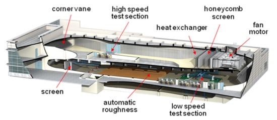
Figure 1.
KOCED wind tunnel at Jeonbuk (Chonbuk) National University.
The free stream velocity was measured using two pitot tubes and pressure transducers (Setra 239). A Vinotech GHP-20R sensor was used to monitor any temperature and humidity changes during the measurements. A Dantec CTA-90C10 constant temperature anemometer, incorporated with the Dantec 55P11 hotwire sensor, was used to measure the turbulent wind velocity. The aerodynamic forces acting on the model were measured using a JR3 external balance that can read forces in three directions and the associated moments. The external balance was checked by applying a static load onto the vessel model, along each of the three directions [13]. Figure 2 shows the FPSO vessel model installed in the wind tunnel test section.
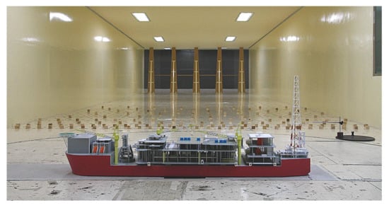
Figure 2.
FPSO vessel model in the test section.
2.2. Boundary Layer Profile
Two atmospheric boundary layer profiles of the mean wind velocity—the Norwegian Maritime Directorate (NMD) model and the Frøya model—were used in the wind tunnel tests [14,15]. In this study, the reference wind speed, U, is the 10 min averaged speed at a height of 10 m above sea level. The NMD profile fundamentally uses the power law to model the wind speed variation over the sea level. The NMD mean wind velocity profile is given by
where H is the reference height (10 m) and α is the roughness exponent, set to 0.14 in this study. The Frøya model provides the mean wind speed profile for offshore locations, as a function of the average period and height above sea level. This model implies that Equation (2) can be used to convert the hourly mean wind speed U0 at height H above sea level, to the mean wind speed U with average period T at height z above sea level.
where H = 10 m, T0 = 1 h and T is 10 min in this study.
, and .
The boundary layer profiles were simulated using spires at the inlet of the test section, and roughness elements were distributed over the tunnel floor [14,15]. Figure 3 shows the curves representing the measured and targeted velocity profiles corresponding to both the NMD model (exponent = 0.14) and the Frøya model. The turbulence intensity profile is shown as a function of the height above sea level.
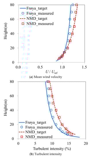
Figure 3.
Boundary layer wind profiles in the wind tunnel.
2.3. Coordinate System and Aerodynamic Coefficient
The coordinate system for the forces, moments, and wind directions is shown in Figure 4. The origin is in the waterline. The direction of positive x is from stern toward bow. The direction of positive y is from starboard toward portside. The direction of positive z is upward from keel toward deck. The signs of the rotations are right-handed. The positive rotations around x, y, and z axes are portside up, stern up, and anticlockwise in the plan view, respectively. The wind azimuth angle is 0° when the wind blows from stern to bow, and 90° when the wind blows from starboard to port.
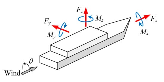
Figure 4.
Coordinate system for forces, moments, and wind directions.
The measured aerodynamic forces and moments are converted into aerodynamic coefficients. The measured forces and moments are nondimensionalized by wind velocity, air density, and reference geometry. The positive aerodynamic coefficient is consistent with the definition of the axis and rotation in the coordinate system. The aerodynamic force and moment coefficients are defined as follows:
where U is the 10-min averaged reference wind speed at 10 m above sea level, ρ is the air density (1.225 kg/m3) at 15 °C, LX,Y,Z is the reference length, and AX,Y,Z is the reference projection area. The blockage ratio of the projected area of the vessel divided by the cross-sectional area of the wind tunnel test section was less than 5% at all wind azimuth angles. Accordingly, the measured aerodynamic coefficients were not corrected for the blockage effect [16,17,18,19].
An FPSO vessel, except for the hull, mostly consists of bluff bodies that are known to be less sensitive to the Reynolds number effect. Prior to the main tests, aerodynamic forces and moments were initially measured for a wide range of wind speeds. These initial measurements were carried out through the mounting of the model on an external balance. Figure 5 shows the relation between the aerodynamic coefficients and the wind speed in the wind tunnel. The aerodynamic coefficients are consistent when the wind speed exceeds 8 m/s. Accordingly, the main tests were performed at a wind speed of 9 m/s to ensure that the aerodynamic forces were insensitive to the Reynolds number.
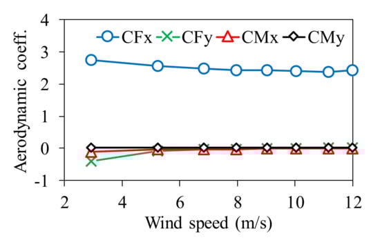
Figure 5.
Variation of aerodynamic coefficients with wind speeds.
2.4. Test Model
The scale of the FPSO vessel model was determined to be 1:200 when considering the blockage ratio, the capacity of external balance, the available wind speed range for the wind tunnel, etc. The elements of the vessel model were conscientiously reproduced using laser cutting and 3-D printing techniques.
Most of the wind tunnel tests had been performed prior to the completion of the detailed design. Consequently, the topside models were developed on the basis of the drawings at an intermediate design stage, which were generally more elementary than the final drawings. To investigate the effect of the simplification of the topside structures, three different topside models, each with a distinct level of detail, were developed as shown in Figure 6. The high-detail model corresponds to a very detailed topside model, with all facilities and ducts thoroughly reproduced as in the final drawing. The medium-detail model simplifies some complicated facilities into porous materials with a similar projection area. The low-detail model is a rough schematization, which only reproduces the outline and projected area of the topside structures.
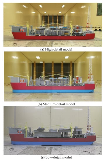
Figure 6.
Topside structures with three different levels of detail.
2.5. Test Case
The model could be turned 360° in the wind tunnel to expose it to flow from all possible relative wind directions. The test cases are summarized in Table 1. The wind tunnel tests were performed to determine the effects of three specific parameters on the aerodynamic forces and moments. The first parameter is the level of detail of the topside structures. Test case numbers from C01 to C06 in Table 1 are designated to verify the effect of the level of detail. The second parameter is the effect of the boundary layer profiles. Test case numbers C01 and C07 have been assigned to compare the NMD wind profile with the Frøya profile. The third parameter is the relative contribution of each topside block to the overall aerodynamic forces, corresponding to test case numbers C07–09. In test case numbers C08 and C09, the S1 and S2 blocks (see Figure 7) of the topside structure were deliberately removed from the model. The effects of the crane itself and its operation mode were tested in test case numbers C07, C10, and C11, respectively. The parking mode of the crane was at the point in which the jib axis coincided with the ship axis. In the operating mode, the two axes were 90 degrees apart. It was assumed that all three cranes were in the same direction.

Table 1.
Test cases.
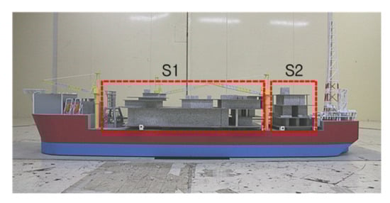
Figure 7.
Topside blocks.
3. Results
This section presents the effects of the topside detail level, boundary layer wind profiles, topside structures, and crane positions on the overall aerodynamic forces through the wind tunnel tests. All of the aerodynamic forces and moments measured in the wind tunnel tests were converted into aerodynamic coefficients using Equations (3) and (4). When applying Equations (3) and (4), the reference projection area of the high-detail model was used regardless of the model type. For relative comparison, the aerodynamic force and moment coefficients were normalized by dividing by the maximum absolute values of CFx and CMx in each case, respectively. The vertical axis of graphs in this section represents the normalized coefficients.
3.1. Impact of the Topside Detail Level
The wind tunnel test results for case numbers C01–C06 are presented in Figure 8 for the forces and in Figure 9 for the moments. The tests were performed under the Frøya profile, and the draughts were 23.5 m in the first three cases, and 11.6 m in the rest. The degree of the topside structures’ modeling were divided into high-, medium-, and low-detail models. Table 2 compares the ratio of the maximum aerodynamic forces measured using three models. The force and moment about the z-axis were too small to compare the relative difference and, hence, omitted from the table.
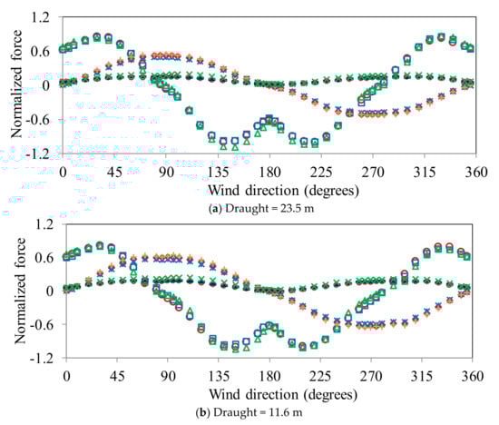
Figure 8.
Normalized aerodynamic force coefficients for three FPSO models with different levels of detail in Frøya profile.  : CFx(high),
  : CFx(medium),
  : CFx(low),
  : CFy(high),
  : CFy(medium),
  : CFy(low),
  : CFz(high),
  : CFz(medium),
  : CFz(low).
: CFx(high), : CFx(medium), : CFx(low), : CFy(high), : CFy(medium), : CFy(low), : CFz(high), : CFz(medium), : CFz(low).
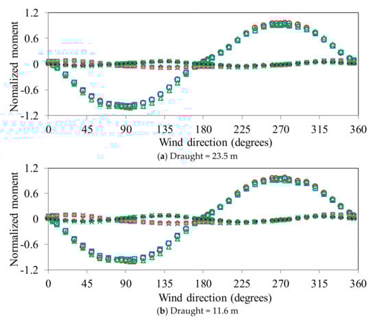
Figure 9.
Normalized aerodynamic moment coefficients for three FPSO models with different levels of detail in Frøya profile. : CMx(high), : CMx(medium), : CMx(low), : CMy(high), : CMy(medium), : CMy(low), : CMz(high), : CMz(medium), : CMz(low).
: CMx(high), : CMx(medium), : CMx(low), : CMy(high), : CMy(medium), : CMy(low), : CMz(high), : CMz(medium), : CMz(low).
Table 2.
Ratio of maximum aerodynamic coefficients of high(H)-, medium(M)-, and low(L)-detail models.
Compared to the high-detail model, CFx of the medium-detail and low-detail models differed by −0.1% and −8.7%, respectively. In the case of CFy, the ratios of medium-detail and low-detail to high-detail were 5.0% and −3.0%, respectively. The maximum values of CFx and CFy were in the order of low > high ≈ medium. The values of CMx in medium- and low-detail models were 2.8% and −2.5%, respectively—different from that of the high-detail model. The difference in the value of CMy was noticeable. The value of CMy of the high-detail model was 9.1–16.9% lower than those of medium- and low-detail models. The maximum moments were generally in the order of low > high ≈ medium.
When the draught changed from 23.5 m to 11.5 m, the difference in moments between the three models decreased. The force ratios of medium detail and low detail to high detail were in the range of −3.6% to 4.3%. The moment ratios varied from −5.7% to 4.7%. The maximum forces and moments at a draught of 11 m were mostly in the order of low > high ≈ medium. The aerodynamic forces and moments measured in this study for the low-detail model were predominantly greater than those for the high-detail model. Moreover, the measured wind loads on the medium-detail model were comparable to those for the high-detail model. The observed results reveal that a low-detail model provides significant conservative wind loads compared to a high-detail model. The lack of porosity of the low-detail model is the principal cause of its higher forces. It is also evident that a medium-detail model is more appropriate to reproduce wind loads compared to a low-detail model, if a high-detail model is not available.
3.2. The Impact of Wind Profiles
Figure 10a,b shows the effect of boundary layer profiles on the aerodynamic forces and moments, respectively. In the entire range of varying wind directions, the measured wind loads (absolute values) corresponding to the NMD profile were observed to be greater than those corresponding to the Frøya profile, with the differences being in the range of 18.1% to 19.5% at maximum force and moment. As evidently shown in Figure 3, the mean wind speeds of the NMD profile with a roughness exponent of 0.14 were, to some extent, higher than those of the Frøya profile, thereby resulting in the increased wind loads.
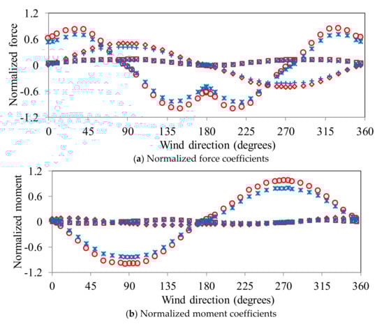
Figure 10.
Normalized aerodynamic coefficients for FPSO model under NMD and Frøya profiles (medium-detail model, draught = 23.5 m). : CFx(NMD), : CFy(NMD),  : CFz(NMD), : CFx(Frøya),
  : CFy(Frøya),
  : CFz(Frøya).
: CFx(NMD), : CFy(NMD), : CFz(NMD), : CFx(Frøya), : CFy(Frøya), : CFz(Frøya).
3.3. Impact of Topside Blocks
Figure 11a,b show, respectively, the comparison of the aerodynamic forces and moments of the FPSO models with their entire topside structures, having both S1 and S2 blocks. When the model had S1 block only, the wind loads reduced in the range of 0.8–10.9%. When the model had S2 block only, the aerodynamic forces and moments decreased in the range of 5.6–20.7%. When either the S1 or S2 blocks were removed, the aerodynamic moment coefficients at 90 and 270 degrees were different. This is because the topside block, a hydrocarbon processing plant, is asymmetrical, while the vessel itself is symmetrical. It was found that the aerodynamic force varied in proportion to the projected area of the plant structures, such as S1 and S2.
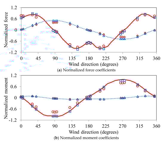
Figure 11.
Normalized aerodynamic coefficients for FPSO model (NMD profile, medium detail, draught = 23.5 m).  : CFx(S1+S2), : CFx(S2), : CFx(S1),
  : CFy(S1+S2), : CFy(S2),
  : CFy(S1).
: CFx(S1+S2), : CFx(S2), : CFx(S1), : CFy(S1+S2), : CFy(S2), : CFy(S1).
The effects of cranes and their operation modes on the wind loads are presented in Figure 12a,b. By comparing the parking and operating modes of the crane, the wind loads were observed to increase by up to 8.6% at the operating mode. This impact occurred predominantly on the forces (CFx and CFy) rather than on the moments. The wind loads decreased by up to 6.4% when we removed the cranes from the vessel model. In this case, the impact is observed mostly on the moments. Because the plant structures were densely placed at topside, the cranes of a similar height to the plant structure had little effect on the aerodynamic coefficients.
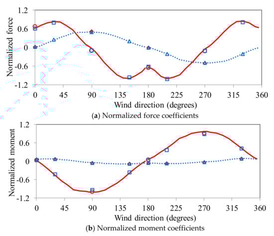
Figure 12.
Normalized aerodynamic coefficients for FPSO model according to crane modes (NMD profile, medium detail, draught = 23.5 m). : CFx(parking), : CFx(operating), : CFx(w/o crane), : CFy(parking), : CFy(operating), : CFy(w/o crane).
: CFx(parking), : CFx(operating), : CFx(w/o crane), : CFy(parking), : CFy(operating), : CFy(w/o crane).
4. Conclusions
This study investigated the impact of the wind profiles, the level of detail of the topside structures, and the operation modes of the gantry cranes on the wind loads. The primary observations can be summarized as follows.
The wind loads measured using the high-detail model were less than those of the low-detail model and were similar to those of the medium-detail model. The maximum difference of wind loads among the three models was 16.9%. The measured aerodynamic forces and moments followed an order of low detail > medium detail ≈ high detail. The lack of porosity of the low-detail model is the principal cause of its higher forces.
The measured wind loads corresponding to the NMD profile with a roughness exponent of 0.14 were observed to be greater by an amount ranging between 18.1% and 19.5%, than those corresponding to the Frøya profile. This is a consequence of the mean wind speeds of the NMD profile being greater, to some extent, than those of the Frøya profile.
The observed wind forces increased by up to 8.6% when the cranes were at operating mode compared to at parking mode. This effect is observed predominantly on the forces rather than on the moments. The wind loads decreased by up to 6.4% when the cranes were removed from the vessel model.
The FPSO vessels with many structures installed on the topside receive much more wind load than general vessels; therefore, the measurement results varied depending on how the model was developed in the wind tunnel experiment. Until now, these modeling methods had relied on the experience of the wind tunnel test institutes. In the future, the wind tunnel test institutes are expected to set the guideline for appropriate modeling methods through benchmark tests [18].
Author Contributions
S.L. (Sanghun Lee) and S.-D.K. designed the experiments; S.L. (Seungho Lee) conducted wind tunnel tests; S.L. (Seungho Lee) and S.-D.K. analyzed and wrote the paper. All authors have read and agreed to the published version of the manuscript.
Funding
This research was supported by a grant(20CTAP-B132923-04) from Technology Advancement Research Program (TARP) funded by Land, Infrastructure and Transport of Korean government.
Acknowledgments
Authors would like to extend our thanks to the Daewoo Shipbuilding & Marine Engineering Company for their help in offering us the necessary data and technical supports for experiments.
Conflicts of Interest
The author declares no conflict of interest.
References
- Penalba, M.; Ulazia, A.; Sáenz, J.; Ringwood, J.V. Impact of Long-term Resource Variations on Wave Energy Farms: The Icelandic case. Energy 2020, 192, 116609. [Google Scholar] [CrossRef]
- Reguero, B.G.; Losada, I.J.; Méndez, F.J. A recent increase in global wave power as a consequence of oceanic warming. Nat. Commun. 2019, 10, 1–14. [Google Scholar] [CrossRef] [PubMed]
- API. Recommended Practice for Planning, Designing and Constructing Fixed Offshore Platforms—Load and Resistance Factor Design; API Recommended Practice 2A-LRFD (RP 2A-LRFD); API: Washington, DC, USA, 1993. [Google Scholar]
- De Kat, J.O.; Wichers, J.E.W. Behavior of a moored ship in unsteady current, wind, and waves. Soc. Nav. Archit. Mar. Eng. Mar. Technol. 1991, 28, 251–264. [Google Scholar]
- Hwang, S.H.; Cho, S.K.; Sung, H.G.; Hong, J.P.; Vazquez-Hernandez, A.O. Experimental and Numerical Study of the Environmental Loads on a FPSO. In Proceedings of the 26th International Ocean and Polar Engineering Conference, Rhodes, Greece, 26 June–2 July 2016. [Google Scholar]
- Wichers, J.E.W. A Simulation Model for a Single Point Moored Tanker. Ph.D. Thesis, Delft University of Technology, Delft, The Netherlands, 1988. [Google Scholar]
- Duggal, A.S.; Heyl, C.N.; Poranski, P.F. Nova FPSO: Integration of Model and Global Analysis. In Proceedings of the 10th International Offshore and Polar Engineering Conference, Seattle, WA, USA, 28 May–2 June 2000. [Google Scholar]
- Kim, M.H.; Koo, B.J.; Mercier, R.M.; Ward, E.G. Vessel/mooring/riser coupled dynamic analysis of a turret-moored FPSO compared with OTRC experiment. Ocean Eng. 2005, 32, 1780–1802. [Google Scholar] [CrossRef]
- Palazzo, F.G.; Sparano, J.V.; Simos, A.N.; Masetti, I.Q.; Tannuri, E.A. Evaluation of the Dynamic Behavior of the P50 FPSO System Using Dynasim: Comparison with Experimental Results. In Proceedings of the 22nd International Conference on Offshore Mechanics and Arctic Engineering (ASME 2003), Cancun, Mexico, 8–13 June 2003. [Google Scholar]
- Sphaier, S.H.; Fernandes, A.C.; Correa, S.H. Maneuvering model for the FPSO horizontal plane behavior. In Proceedings of the Tenth International Offshore and Polar Engineering Conference, Seattle, WA, USA, 28 May–2 June 2000. [Google Scholar]
- Lee, D.H.; Choi, H.S. A dynamic analysis of FPSO-shuttle tanker system. In Proceedings of the 10th International Offshore and Polar Engineering Conference, Seattle, WA, USA, 28 May–2 June 2000; ISOPE: Seattle, WA, USA, 2000; Volume 1, pp. 302–307. [Google Scholar]
- Wichers, J.; Devlin, P.V. Benchmark Model Tests on the DeepStar Theme Structures FPSO, SPAR and TLP. In Proceedings of the Offshore Technology Conference, Houston, TX, USA, 3–6 May 2004. [Google Scholar]
- Barlow, J.B.; Rae, W.R.; Pope, A. Low-Speed Wind Tunnel Testing; John Wiley & Sons: New York, NY, USA, 1999. [Google Scholar]
- Det Norske Veritas AS. Recommended Practice—Environmental Conditions and Environmental Loads; DNV-RP-C205; DNV: Oslo, Norway, 2007. [Google Scholar]
- Norwegian Maritime Directorate. Wind Tunnel Tests Procedure, Regulations for Mobile Drilling Platforms. In Proceedings of the 10th International Offshore and Polar Engineering Conference, Seattle, WA, USA, 28 May–2 June 2000; Volume 1, pp. 334–337.
- Irwin, H.P.A.H. The design of spires for wind simulation. J. Wind Eng. Ind. Aerodyn. 1981, 7, 361–366. [Google Scholar] [CrossRef]
- Simiu, E.; Scanlan, R.H. Wind Effects on Structures: An Introduction to Wind Engineering; John Wiley & Sons: New York, NY, USA, 1996. [Google Scholar]
- Society of Naval Architects and Marine Engineers. Guidelines for Wind Tunnel Testing of Floating Offshore Installations; Technical & Research Bulletin 5-4 (TR 5-4); The Society of Naval Architects and Marine Engineers: Alexandria, VA, USA, August 1988. [Google Scholar]
- ASCE. Wind Tunnel Testing for Buildings and Other Structures; Standard ASCE/SEI 49–12; American Society of Civil Engineers: Reston, VA, USA, 2012. [Google Scholar]


© 2020 by the authors. Licensee MDPI, Basel, Switzerland. This article is an open access article distributed under the terms and conditions of the Creative Commons Attribution (CC BY) license (http://creativecommons.org/licenses/by/4.0/).