Article

Analysis of Sealing and Leakage Performance of the Subsea Collet Connector with Lens-Type Sealing Structure

Harbin Engineering University, No. 145 Nantong Street, Nangang District, Harbin 150001, China
*
Authors to whom correspondence should be addressed.
J. Mar. Sci. Eng. 2020, 8(6), 444; https://doi.org/10.3390/jmse8060444
Submission received: 12 May 2020 / Revised: 6 June 2020 / Accepted: 12 June 2020 / Published: 17 June 2020
(This article belongs to the Section Ocean Engineering)

Abstract

:
The contact mechanics model of the metal lens-type sealing gasket is established on the basis of Hertz theory on the macroscopical scale in this paper. The relationship among sealing width, contact pressure, and preload is solved. Based on the structural characteristics of the subsea collet connector, the self-locking characteristics are analyzed to determine the gain coefficient of the sealing structure for the loading thrust. On the microscopic scale, the contact characteristics of the turning lens-type sealing gasket and the hub structure are analyzed by the equivalent replacement of the peak cut coefficient of the one-dimensional sinusoidal wave. The influence of different leakage forms on sealing performance is discussed from both radial and circumferential leakage, and the leakage rate of the lens-type sealing structure is calculated. The hydrostatic pressure experiment of the subsea collet connector with lens-type sealing gasket is carried out, and the correctness of the theoretical analysis is verified from the results of the pressure maintaining, sealing width measurement, and preload conversion.

1. Introduction

The connection and seal of the subsea oil and gas production system is an internationally recognized technical problem. Subsea collet connectors are widely applied to the subsea connection with the characteristics of the reliable connection, high sealing pressure, and automatic connection [1]. The working environment of the subsea connector is characterized by high pressure, low temperature, strong ocean current impact, and extremely low visibility. The quality of the sealing technology influences the success of the subsea connection, and the sealing failure will cause unforeseen disasters [2].
Scholars have done a lot of research on the seal and leakage of flange and sealing gasket connection structure. Payne et al. [3] proposed the definition of tightness, which was the comprehensive analysis result of combining the internal pressure and leakage rate of the sealing medium, and mainly used to characterize the sealing performance. Based on fractal geometry theory, Feng et al. [4,5] established the metal gasket leakage model, by combining the appearance of the machined surface with the sealing leakage channel model and assuming the medium of an incompressible fluid. The larger the fractal dimension of the sealing surface was, the less probable leakage was to occur. The processing quality of the sealing surface was significant for the sealing of flange and metal sealing gasket. Zhao et al. [6] studied the sealing mechanics of the metal seal ring of the underwater wellhead connector and obtained the sealing load of the metal seal ring under the action of residual pre-tightening load, which could prevent the sealing ring from yielding and was verified by finite element simulation. Wei et al. [7] analyzed the critical state of the seal, deduced the critical mean contact pressure formula to ensure the seal. Through the sealing indentation experiment, it was concluded that when the mean contact pressure is greater than the critical mean contact pressure, and the contact pressure variance was small, a full-contact seal was formed. Considering the hysteresis of the stress-displacement of gaskets, Sawa T et al. [8] obtained the relationship between gaskets stress and leakage rate based on the finite element analysis and gasket sealing test and examined the method of estimating leakage amount. Liu et al. [9] analyzed the sealing performance of the casing reinforcing thread and obtained the effect mechanism of thread parameters on the sealing performance. Yun et al. [10] established mechanical models of the seal, analyzed the relationships of structural parameters and the preload. Zhang et al. [11] put forward a theoretical method to calculate the compression limits of the sealing structure of the subsea connector and founded that the amount of the compression deformation was related to the compression load between the contact surfaces. Wang et al. [12] analyzed the mechanism of static metal sealing, determined the critical condition of the sealing performance, and established the method of calculating the contact pressure of the sealing surface. Shao et al. [13] proposed a static seal interface leakage channel prediction method, which included contact generation, leakage parameter definition, and channel prediction, and the experimental results showed that this method could evaluate the static sealing performance well. Lutkiewicz et al. [14] proposed a method for evaluating the effectiveness of bolted joint seals based on leakage rate calculation, which took the contact stress graphs, material characteristics, and surface roughness as input and obtained the leakage rate evaluation value. Wang et al. [15] proposed a new method for detecting leakage location and measuring leakage rate based on temperature field and temperature gradient field and verified the feasibility of the method by experiments. Li et al. [16] established the G-L Reynolds equation based on equivalent density and viscosity of the gas-liquid fluid, and the theoretical results are verified by the experiment. Wu et al. [17] proposed a new method for numerical simulation of local leakage in the lining of the shield tunnel, which overcame the limitation of the solid meshing of the leakage unit and reduced the calculation error caused by the size difference between solid leakage unit and lining unit. Zhu et al. [18] analyzed the leakage of the operating rotary air preheater, built a direct leakage set-up, and the experimental and analytical results showed that the total pressure difference between the two sides of the seal was the main reason for the local direct air leakage. Menga [19] studied the rough contact mechanical behavior of thin elastic layers in the presence of coulomb friction interaction; under the framework of linear elasticity mechanics, a new basic solution for thin layers under the action of the periodic concentrated tangential load is proposed; the calculation shows that local friction and finite-size effect can significantly reduce the leakage rate. Menga et al. [20] studied the influence of boundary conditions on sliding contact viscoelastic layers and found that the layer thickness and boundary conditions affect the average contact amount and viscoelastic friction at the same time, and Persson’s theoretical predictions are in good agreement with the numerical calculation.
As can be seen from the above literature review, previous researches mainly studied the deformation, preload, and macroscopical leakage models of seals under various high-pressure conditions. However, the mechanical characteristics, micro-contact characteristics, and leakage modes of the lens-type sealing structure were not considered enough. Therefore, the macroscopical and microcosmic sealing and leakage characteristics of the metallic lens-type sealing structure of the subsea collet connector is analyzed in this article. The pre-tightening and self-locking characteristics of the lens-type sealing structure on a macroscopic scale is presented firstly. Afterward, contact characteristics and the leakage rate of the lens-type sealing gasket are analyzed from the microscopic scale. The correctness of theoretical analysis results is verified by the hydrostatic pressure experiment.

2. Subsea Collet Connector Structure

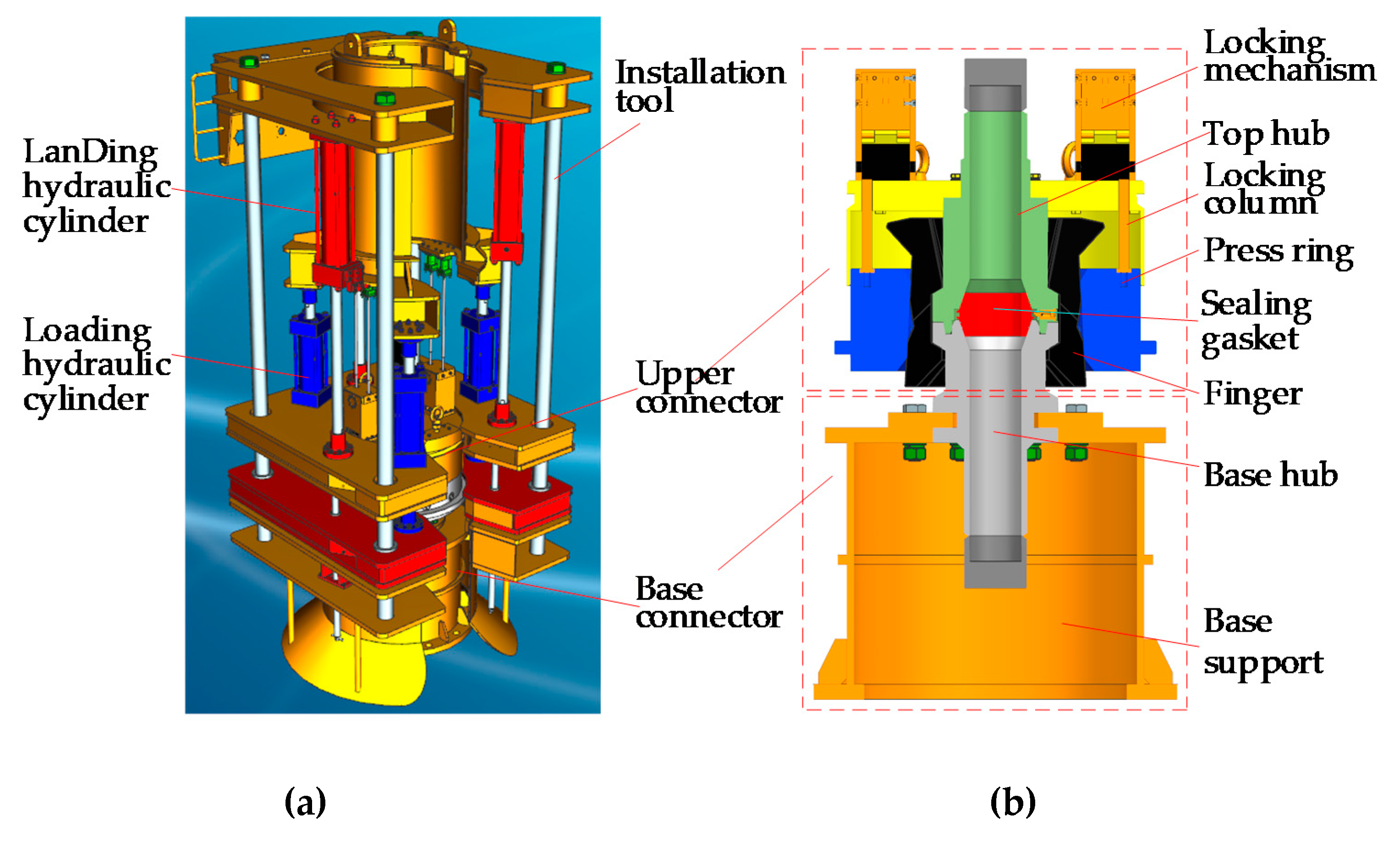
A split subsea collet connector with a working water depth of 2000 m is developed in this article. As shown in Figure 1 and Figure 2, a subsea collet connector is composed of an installation tool, upper connector, and base connector. When connecting underwater, two subsea collet connectors work together. The hub ends of two upper connectors are welded with the two ends of one jumper, and two installation tools carry two upper connectors respectively to connect two base connectors. The connector installation tool hydraulic power is directly provided by the ROV (remotely operated vehicle). Each hydraulic valve on the ROV’s operation control panel can be remotely controlled to achieve the underwater installation of the connector. After completing the underwater installation of the subsea collet connector, the ROV operates the installation tool to detach from the connector and it will be withdrawing to the mother ship.
As shown in Figure 2b, the press ring exerts thrust on fingers to make fingers inward and achieve the tightness of the top and base hubs in the initial connection process, which provides preload for the seal of the subsea collet connector. When high-pressure fluid flows through the inner cavity of the connector, the high pressure acts on the sealing gasket and hubs. Two hubs have a tendency to be separated, and they will push the fingers. Therefore, the fingers and the press ring need to be self-locked. In order to ensure the subsea collet connector a well-sealing performance, the key theory should be analyzed in detail.

3. Mechanical Study on Lens-Type Sealing Structure of Subsea Collet Connector

Non-standard metal lens-type sealing gasket is used in subsea collet connector. The sealing width, contact pressure mean value, and contact pressure distribution is the key parameters to describe the sealing characteristics of the lens-type sealing structure. The standard metal lens-type sealing gasket obtains the above parameters mainly relying on the empirical formula, which is not applicable to the non-standard sealing gasket in this article. Therefore, it is necessary to study the non-standard metal lens-type sealing structure.

3.1. Analysis of Axial Preload of Sealing Structure

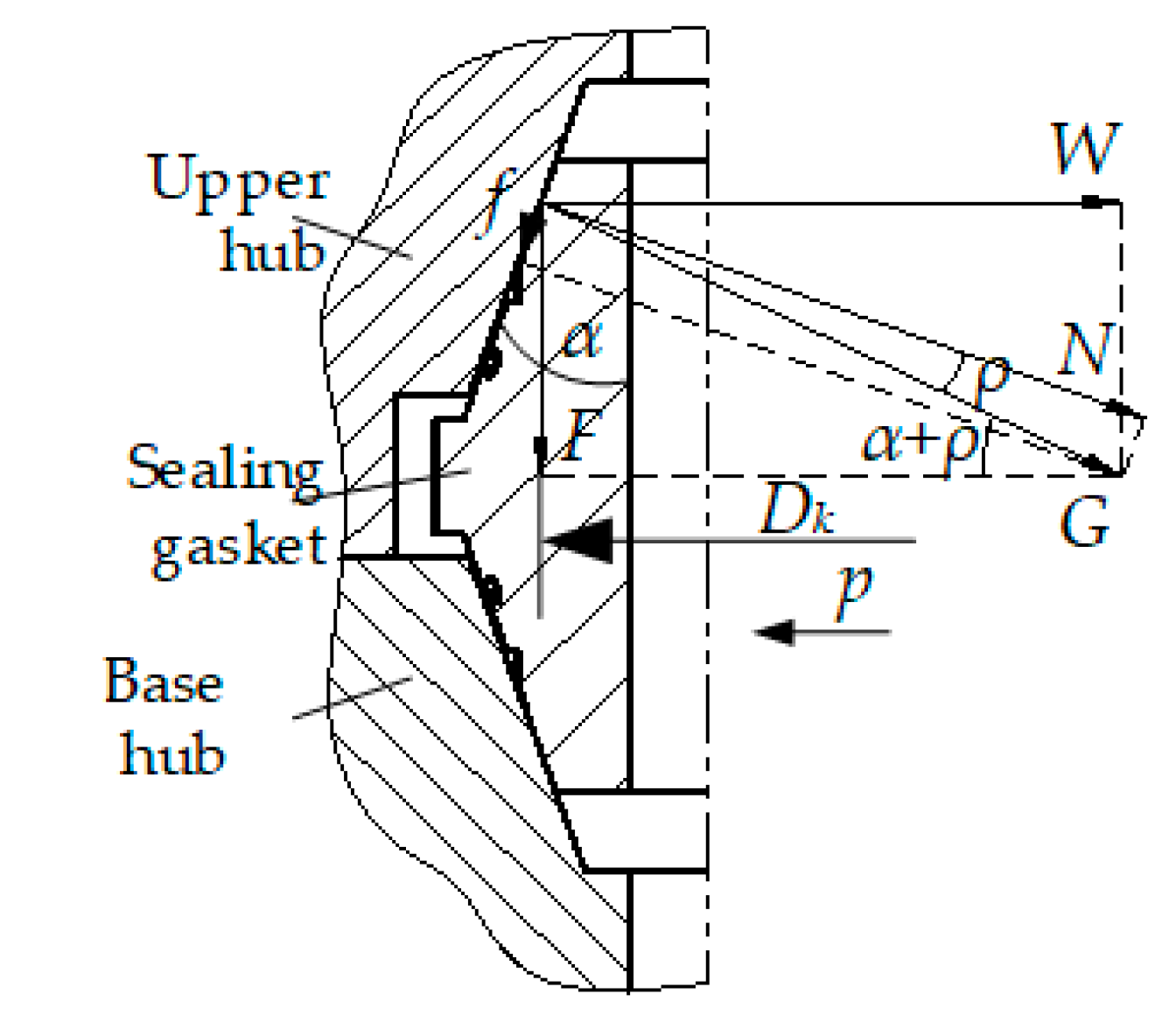
The sealing characteristics of the sealing structure are determined by the sealing width and contact pressure, which are mainly related to the axial preload acting on the sealing structure. As shown in Figure 3, during the service of the connector, hubs exert axial preload F on the lens-type sealing structure, which tends to move downward relative to the tangent plane of the sealing gasket, so the sealing gasket is subject to friction force f. The normal force N of hubs acting on the seal spherical surface is:
N = F cos ρ sin ( α + ρ )
where α is the bevel angle of the hub; ρ is the frictional angle between hubs and sealing gasket, ρ = arctan(µ) = 8.531° with the steel-to-steel friction coefficient of µ = 0.15. The diameter of the contact center between the hub and the sealing gasket is denoted as Dk, and the line load on the contact area is:
N 0 = N π D k = F cos ρ π D k sin ( α + ρ )
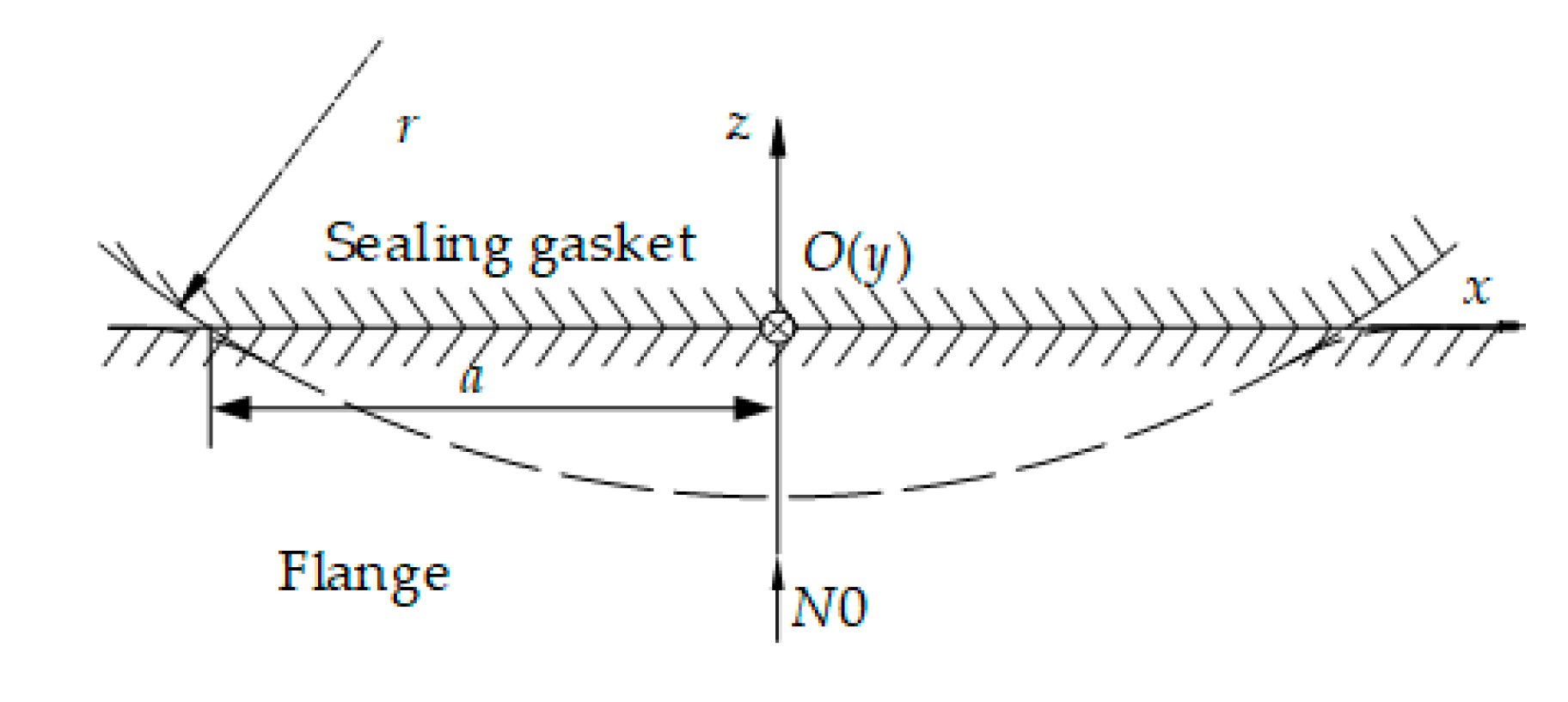
As shown in Figure 4, when the sealing gasket contacts with the hub, the surface of the sealing gasket will be deformed due to the hardness of the hub is higher than that of the sealing gasket. The initial contact line will be expanded into a strip [21], and the width of the axial section of the contact is the sealing width of the sealing gasket. The sealing half-width is indicated by a and the radius of the sealing sphere is indicated by r. Incoloy 825 is chosen as the sealing gasket material with the elastic modulus E1 = 1.95 × 10⁵ MPa, Poisson’s μ1 = 0.25, and yield limit σs1 = 220 MPa. 12Cr2Mo1 is chosen as the hubs’ material with the elastic modulus E2 = 2.1 × 10⁵ MPa, Poisson’s ratio μ2 = 0.3, yield limit σs2 = 310 MPa. Therefore, the equivalent elastic modulus E* can be expressed as:
1 E * = 1 μ 1 2 E 1 + 1 μ 2 2 E 2 = 1 1.126 × 10 5 MPa
As for the contact part of space expansion, the contact of any sealing element can be regarded as the contact between a cylinder and a plane, and we can make the following contact assumptions: (1) For this non-conforming surfaces contact, it is considered that each surface is smooth on both macroscopic and microscopic scales, and the contact is frictionless; (2) the deformation of the sealing contact within the elastic range is small; (3) The contact objects are regarded as semi-infinite solids instead of thin gaskets [19,20]; and (4) there is only distributed vertical pressure on the contact surface. Therefore, it fits Hertz contact theory and the contact pressure distribution function [22,23], q(x0), can be expressed as:
q ( x 0 ) = { 2 N 0 π a 2 ( a 2 x 0 2 ) 1 / 2 , a x 0 a 0 , x 0 < a & x 0 > a
where N0 can also be represented by the following equation:
N 0 = π E * a 2 4 r
Considering Equations (2) and (5) comprehensively, the sealing half-width of the contact area, a, is:
a = ( 4 N 0 r π E * ) 1 / 2 = 2 π F r cos ρ E * D k sin ( α + ρ )
According to Equation (4), the maximum contact pressure, qmax, occurs at contact center, O (x = 0), then:
q max = F E * cos ρ π 2 r D k sin ( α + ρ )
The mean contact pressure, q ¯ , is:
q ¯ = a a q ( x 0 ) d x 0 2 a = 1 4 F E * cos ρ r D k sin ( α + ρ )
Then the maximum contact pressure can be expressed as:
q max = 4 q ¯ π
During the service of the subsea collet connector, there is no pressure in the inner cavity initially, and the fingers hold the hubs to exert a preload on the sealing gasket. When the internal medium begins to flow, the contact pressure of the sealing contact surface should be large enough to withstand the driving force of the fluid caused by the internal and external pressure difference, so as to realize the sealing. The ratio of the contact pressure and the internal pressure applied to the unit effective area is called the gasket coefficient [10] and is expressed by m. For the sealing gasket in the article, the gasket coefficient m = 6.5 when the material is Incoloy 825. The mean contact pressure of the sealing gasket in the operating mode is q ¯ = mp = 6.5 × 34.5 = 224.25 MPa, which is the minimum preloading specific pressure.
Internal pressure, p, acts on the gap, except for the contact area between the sealing gasket and hubs, causing the two hubs to have a tendency to separate, thus the original axial preload acting on the sealing gasket is reduced. At the same time, the internal pressure p acts on the inner surface of the sealing gasket, which makes the sealing gasket closer to the hub and causes another part of the axial force acting on the sealing gasket. It can be seen that, in the operating mode, the axial load acting on the sealing gasket is composed of two parts [10] one part is the axial load F1 caused by residual preload, and the other part is the axial load F2 caused by internal pressure acting directly on the sealing gasket, namely:
{ F 1 = 2 π D k a q ¯ sin ( α + ρ ) cos ρ F 2 = π D k 2 p 4
Thus, the axial preload F of the sealing gasket in the operating mode is:
F = F 1 + F 2 = 2 π D k a q ¯ sin ( α + ρ ) cos ρ + π D k 2 p 4
Due to Equations (6) and (11), we can see that:
F = 4 D k q ¯ F r sin ( α + ρ ) E * D k cos ρ + π D k 2 p 4
where the radius of the sealing spherical surface r = 168.148 mm; the diameter of the contact center between the hub and the sealing gasket Dk = 171.9 mm; the bevel angle of the hub α = 20°; the frictional angle between hubs and sealing gasket ρ = 8.53°; the equivalent elastic modulus E* = 1.126 × 10 5 MPa . Therefore, we can get that F0.5 = –750.719 or 1066.56. As F0.5 should be positive, we can know that F = 1066.562 = 1.138 × 10⁶ N and a = 2.88 mm.

3.2. Analysis of Self-Locking Ability of the Subsea Collet Connector

The subsea collet connector should have self-locking ability during underwater operation, so as to prevent the connector from loosening due to various complex environmental loads in deep water and causing seal failure. As the press ring directly acts on the fingers to transmit preload, the overall force on the sealing structure is controlled by the press ring. If the press ring has an upward movement trend, the preload of the subsea collet connector will be directly reduced and its sealing characteristics will be adversely affected. Although the subsea collet connector has an anti-loosening mechanism, the anti-loosening mechanism has a certain probability of failure as it works in the highly corrosive seawater for a long time, so the press ring needs to be self-locking.
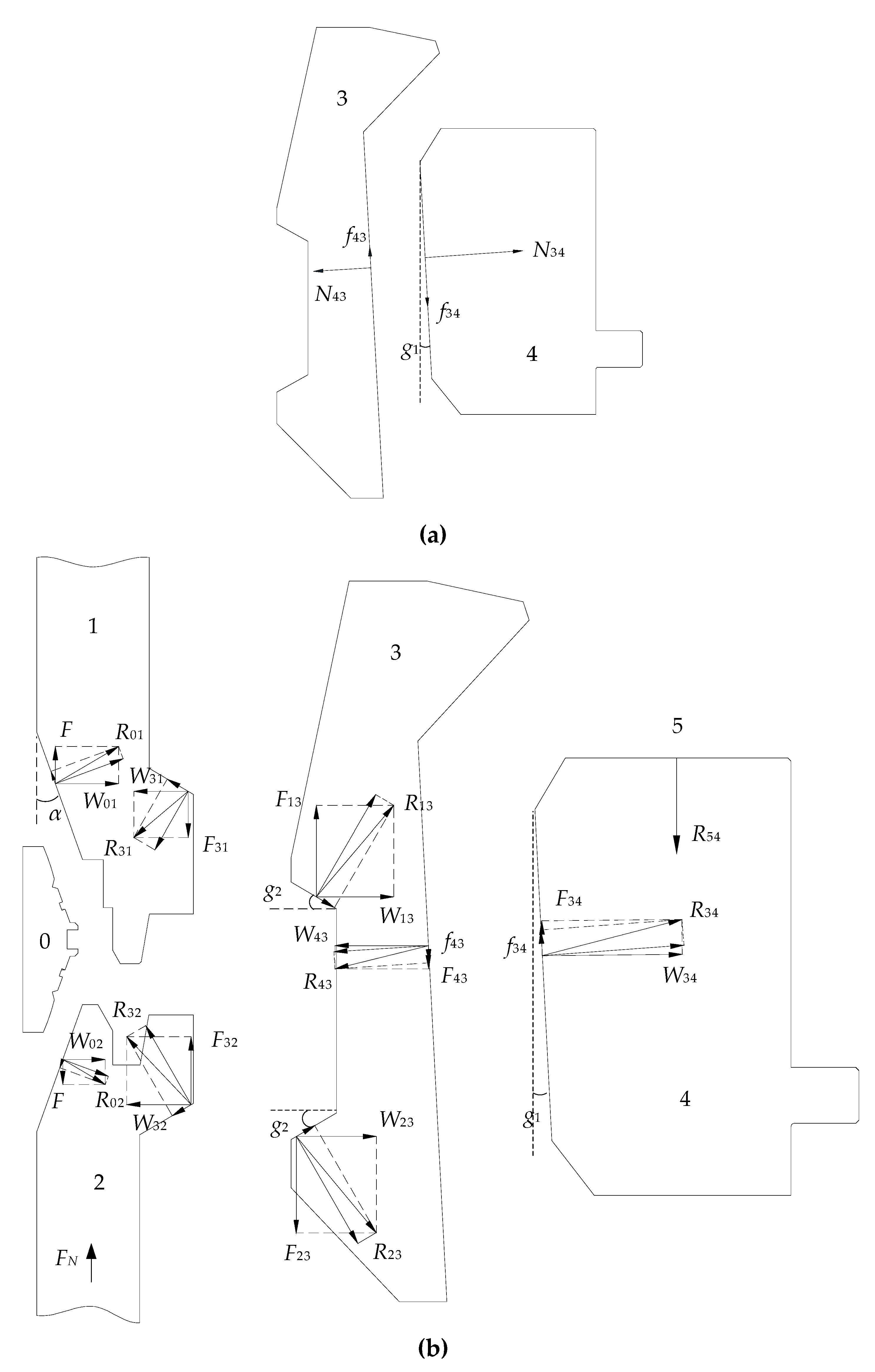
In the operating mode, the anti-loosening effect of the anti-loosening mechanism is ignored. We only consider the self-locking problem of the press ring. As shown in Figure 5, γ1 is the angle of the locking surface between the press ring and the fingers. The material of the press ring and finger is structural alloy steel, 12Cr2Mo1, with steel to steel friction, the friction angle is the same as in the previous section, which can be recorded as ρ = 8.531°. As can be seen from Figure 5, in order to ensure a good self-locking performance of the press ring, the following requirements should be fitted:
f 34 cos γ 1 N 34 sin γ 1
f 34 = N 34 tan ρ
where f34 is the friction force of fingers acts on the press ring; N34 is the positive force of fingers acts on the press ring. Combine Equations (13) and (14), and get:
tan ρ tan γ 1
Whereupon,
γ 1 ρ
Therefore, the angle of the locking surface between the fingers and the press ring, γ1 ≤ 8.531°, taken a safety factor of 3, and γ1 = 2.83°. In order to facilitate processing, the integer γ1 = 3°was taken.

3.3. Analysis of Loading Force of The Connector Sealing Structure

The subsea collet connector requires press ring, fingers, and hubs to transmit preload to the sealing gasket when pre-tensioning, so it is expected a small load on the press ring to realize the sealing of the connector. In the preloading mode, the loading hydraulic cylinder pushes the press ring downward, as shown in Figure 5b, the friction angle between each part is taken as ρ. The preload acting on the sealing gasket is F; the upper hub is subjected to the reaction force of the sealing gasket, R01, and the force R31 applied by the fingers; the base hub is subjected to the support force FN, the reaction force of the sealing gasket, R02, and the force R32 applied by the fingers. The fingers are subjected to the reaction force, R13, of the upper hub, the reaction force, R23, of the base hub, and the force, R43, applied by the press ring. The press ring is subjected to the thrust, R54, of the loading hydraulic cylinder and the reaction force, R34, of the fingers. Where, R13 = R31, R32 = R23 and R43 = R34, they are acting forces and reaction forces. In addition, because the sealing gasket is subject to the simultaneous action of the top and base hubs, according to the balance of forces, the top and base hubs are subjected to the equal forces from the sealing gasket, R01 = R02. The component of these forces in the axial direction is denoted by the symbol of F, and the component in the radial direction by the symbol of W.
The equilibrium equation for the upper hub is:
{ W 01 = W 31 F = F 31
where W01 is the radial component of R01; W31 is the radial component of R31; F31 is the axial component of R31. The equilibrium equation for the base hub is:
{ W 02 = W 32 F = F 32 + F N
where W02 is the radial component of R02; W32 is the radial component of R32; F32 is the axial component of R32. The equilibrium equation for the finger is:
{ W 13 + W 23 = W 43 F 13 = F 43 + F 23
where W13 is the radial component of R13, W13 = F13tan(γ2 + ρ); W23 is the radial component of R23, W23 = F23tan(γ2 + ρ); W43 is the radial component of R43, W43 = F43/tan(γ1 + ρ); F13 is the axial component of R13; F23 is the axial component of R23; γ2 is the sharp angle between the locking surface of the finger and the horizontal direction. The equilibrium equation for the press ring is:
R 54 = F 34 = R 34 sin ( γ 1 + ρ )
Sort Equations(17)–(20), and we can get:
R 54 F = 2 tan ( γ 2 + ρ ) tan ( γ 1 + ρ ) 1 + tan ( γ 1 + ρ ) tan ( γ 2 + ρ )
There is still an unknown variable, γ2, in the upper equation, which can be solved by the lower equation due to the need of getting a larger F with a smaller R54:
2 tan ( γ 2 + ρ ) tan ( γ 1 + ρ ) 1 + tan ( γ 1 + ρ ) tan ( γ 2 + ρ ) < 1
The solution of Equation (22) is γ2 < 69.94°. In order to facilitate processing and calculation, γ2 = 30°. Substitute γ2 into Equation (21), we can obtain that the thrust R54 required for loading hydraulic cylinder is 27.95% of the sealing preload, F, which means that the gain coefficient of the sealing structure for the loading thrust R54 is 3.58. According to Section 3.1, F = 1.138 × 10⁶ N and R54=27.95%F = 3.181 × 10⁵ N.

4. Analysis of Leakage Characteristics of Connector Lens-Type Sealing Gasket

The lens-type sealing gasket is mainly processed by the turning process. Under the influence of feed amount, feed speed, the geometric radius of tool, and other factors, spiral-shaped cutting marks will be generated in micro-scale regardless of the size of the turning surface roughness [24,25]. The main effect of the surface with a certain roughness is the leakage of the sealing gasket. This section will analyze the leakage characteristics of the turning metal lens-type sealing gasket with surface roughness 0.8 μm.

4.1. Microscopic Sealing Contact Process of Turning Surface

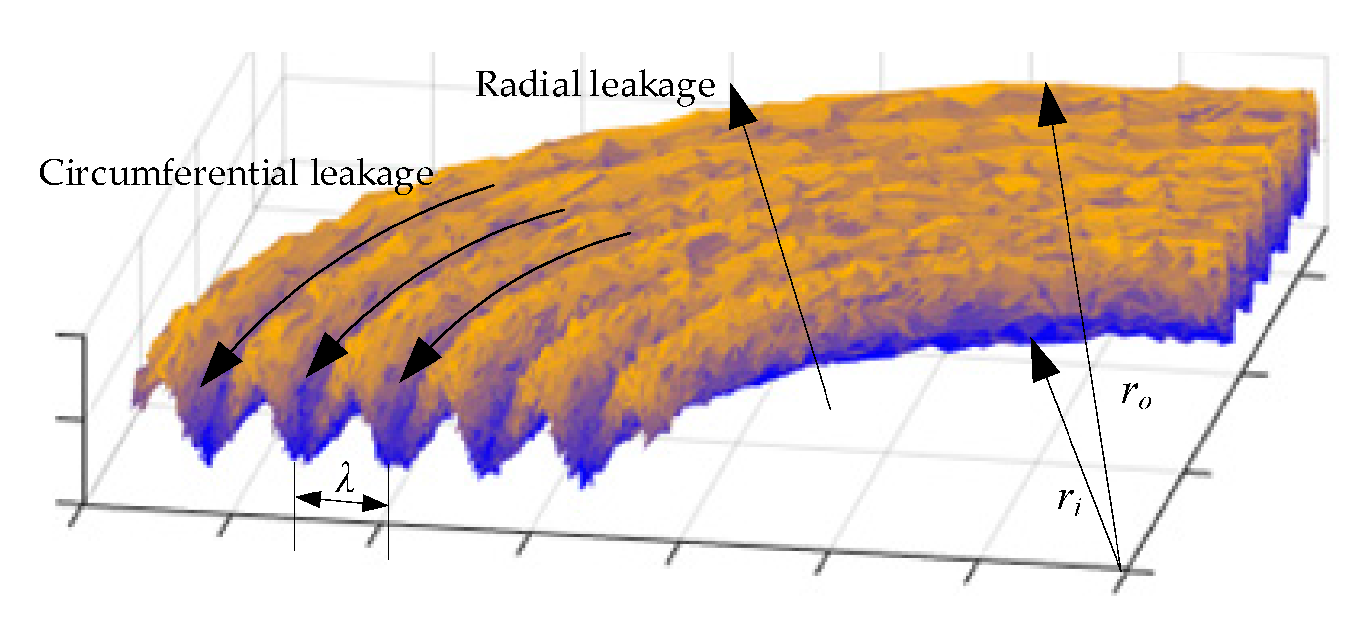
The contact process of the lens-type sealing structure is similar to that of the plane contact, so the sealing of turning metal flat gasket is analyzed firstly. The metal gasket has the coaxiality requirement in the assembly process with the flange. As the sealing structure is very important for the subsea connector, the coaxiality is selected as grade 5, and considering the seal structure dimension, the coaxiality tolerance value is 0.01 mm. In addition, for metal flat gaskets, in order to ensure the assembly accuracy, its flatness should also be grade 5, and its flatness tolerance value is 0.008 mm. In this paper, assuming that (1) the internal surface of the hub is flat, ideal and smooth, (2) the hub and the gasket have the same surface flatness, and (3) the flatness of the turning metal gasket is negligible compared with the surface roughness, thus single asperity conditions of the gasket surface are considered in this paper [19,20]. The micro-morphology of the lens-type sealing gasket on the turning surface [26] is shown in Figure 6. Leakage occurs between the crests or troughs of the helix on the sealing surface when the preload is small or medium. These leakage channels can be divided into radial leakage and circumferential leakage.
In the first stage, when the preload is very small, the contact only occurs on the spiral line with the highest peak of the lens-type sealing gasket. And as a result of the small shape error of the spiral peak, the contact along the spiral line can not maintain continuity, thus forming a radial leakage channel. At this time, the leakage between the hub and the lens-type sealing gasket is the largest.
In the second stage, as the preload increases gradually, the tiny shape error of the spiral wave crest of the lens-type sealing gasket will be plastic deformed. The whole spiral wave crest will contact with hub surface and fill the radial leakage channel. At this time, the circumferential leakage channel becomes the only leakage channel.
In the third stage, when the preload is further increased, the overall micro-morphology of the lens-type sealing gasket will continue to be elastic-plastic deformed or even plastic deformed, and the circumferential leakage channel will be blocked.
When the lens-type sealing gasket is in the second stage, the leakage channel of the turning surface is a spiral structure, the length of the circumferential leakage channel is equal to the sum of the circles between compression crests, which is much greater than the sealing width of the lens-type sealing gasket. Therefore, the difficulty of circumferential leakage is increased, and at the same time, the amount of circumferential leakage is much smaller than the radial leakage. It is considered in this article that for the lens-type sealing with turning surface micromodel in a liquid medium, when the contact pressure is equal to the minimum preloading specific pressure, the micro-leakage channel is a continuous circumferential leakage channel, which is regarded as an effective sealing state at the macroscopic level.

4.2. Microscopic Contact Analysis of Metal Flat Gasket

Real contact areas of lens-sealed contact are only part of macroscopical contact [27] and can be reduced to synthetic rough surface contact with an ideal smooth surface [28]. As the sealing surface of the lens-type sealing gasket and the metal flat gasket are both turning surfaces, there is a certain similarity. Therefore, before investigating the contact of the lens-type sealing gasket, the microscopic contact of the metal flat gasket is firstly analyzed.
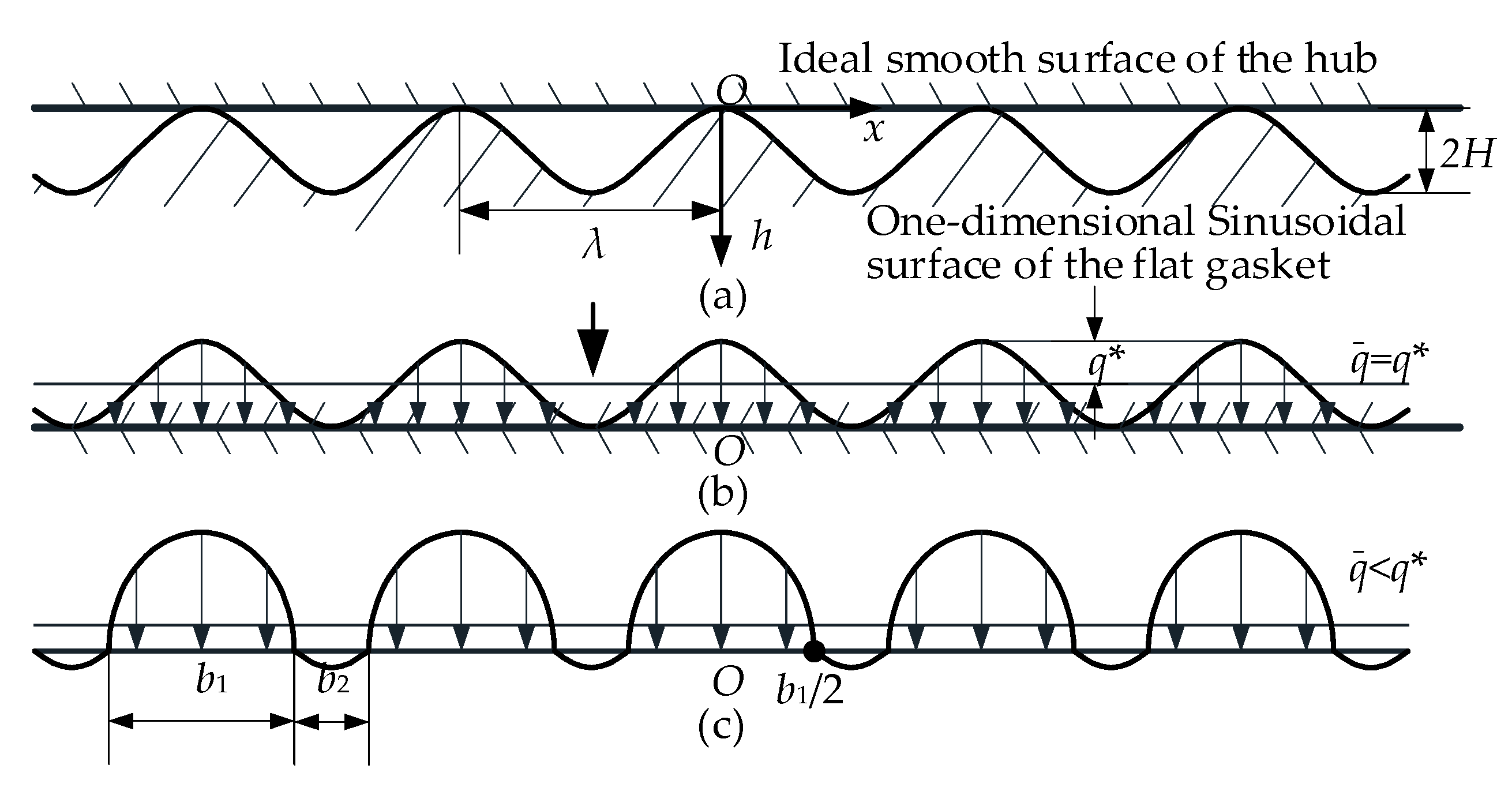
For the sealing surface of the turning metal flat gasket, as shown in Figure 6, it can be approximately regarded as an ideal sinusoidal wave. As shown in Figure 7a, the surface of the synthesized metal flat gasket is a sinusoidal curve of an elastic solid, and the hub is an elastic half-space with an ideally smooth surface. The contact is regarded as a one-dimensional sinusoidal wave with amplitude, H, and wavelength, λ, before being subjected to external loads. As shown in Figure 7a, a cartesian coordinate system is established, and the origin, O, of the coordinate system is the contact center of the space. The gap, h(x), between the upper and lower surfaces can be expressed as:
h ( x ) = H { 1 cos ( 2 π x / λ ) }
Continuous surface contact is formed between the gasket and the hub if a load is applied to the surface of the gasket to such an extent that all surface wave-shaped bulges are compressed to a completely smooth state. For this state, the elastic displacement of the surface is:
u z = u z 1 + u z 2 = h ( x ) + δ
where uz1 and uz2 are the deformation value of the metal flat gasket and hub; δ is the macroscopic compression of the metal flat gasket. If the above contact is regarded as an elastic half-space under sinusoidal surface force, its contact pressure, q(x), should conform to [22]:
q ( x ) = q * cos ( 2 π x / λ )
where q* is the amplitude of contact pressure. Then the elastic displacement of the microscopic surface is:
u z = u z 2 = ( 1 μ 2 2 ) λ π E 2 q * cos ( 2 π x / λ ) + const
where the equivalent elastic modulus can be recorded as 1 / E * = ( 1 μ 2 2 ) / E 2 . Since Equation (26) is the elastic displacement of a single object under the action of force, the equivalent elastic modulus, E * , can be replaced by E* in Equation (3) for the elastic displacement between the gasket and the hub with the sinusoidal wave bulges compressed.
Substitute Equations (23) and (3) into Equations (24) and (26), and compare Equation (24) with Equation (26), we can see that:
q * = π E * H λ
According to Figure 7b, the contact pressure of the surface completely compressed to a smooth state should be satisfied with the following equation:
q ( x ) = q ¯ + q * cos ( 2 π x / λ )
where, q ¯ is the mean contact pressure. In order to keep the contact continuous, the contact pressure should be positive, then q ¯ q*. If the mean contact pressure q ¯ < q*, the two surfaces will be discontinuous contact, as shown in Figure 7c, which will lead to leakage channels. The actual sealing width is b1, and the width of the leakage channel is b2.
The contact pressure distribution function of the discontinuous contact shown in Figure 7c is:
q ( x ) = 2 q ¯ cos ( π x / λ ) sin 2 ( π b 1 / 2 λ ) { sin 2 ( π b 1 / 2 λ ) sin ( π x / λ ) } 1 / 2
The mean contact pressure q ¯ in the equation is:
q ¯ = ( π E * H / λ ) sin 2 ( π b 1 / 2 λ )
The ratio of the actual sealing width to the macroscopic sealing width can be calculated by comparing Equation (27) with Equation (30):
b 1 λ = 2 π arcsin q ¯ q *
Then the ratio of leakage channel width to macroscopic sealing width is:
b 2 λ = 1 b 1 λ = 1 2 π arcsin q ¯ q *
The microscopic surface of the metal flat gasket with contact deformation can be approximated as a curve after the peak is cut off by εH, and ε is the peak cutting coefficient (0 ≤ ε ≤ 2). As can be seen from Figure 7c, for the original curve at b1 / 2:
ε H = h ( b 1 2 ) = H { 1 cos ( b 1 λ π ) }
It can be seen that the peak cutting coefficient of the metal flat gasket is:
ε = 1 cos ( b 1 λ π )
The micro-contact between the metal flat gasket and the hub surface is analyzed above, and the ratio equation of the leakage channel to the wavelength is derived, which is independent of the angle and the sealing sphere radius of the gasket. Therefore, Equation (32) can be used in the study of micro-contact of the lens-type sealing gasket.

4.3. Micro-Contact Analysis of Lens-Type Sealing Gasket

Depending on the analysis in Section 3.1, the maximum contact pressure of the lens-type sealing gasket occurs in the contact center, and the contact pressure of the contact edge is zero. As shown in Figure 8, after the application of the load, the deformation of each microscopic bulge of the lens-type sealing gasket contacted with the hub is independent of each other. The microscopic surface after the contact deformation can be approximated as a curve after the peak is cut off by εiH. εi is the peak cut coefficient (0≤ εi ≤ 2) of the ith period, and H is the amplitude value. As the sealing surface of the lens-type sealing gasket is a curved spherical surface, it can be seen from Figure 8 that the peak value cut off from the contact center is the largest, and the peak value cut off from the contact edge is the smallest.
When the mean contact pressure changes continuously along the x-axis direction, −axa in the sealing width and the change function of the macroscopic contact pressure can be found in Equation (4). Replace the sealing half-width, a, with the sealing width, b, where b = 2a. Thus when −b/2 ≤ xb/2, Equation (4) will be:
q ( x ) = 4 N 0 π b 2 ( b 2 4 x 2 ) 1 / 2
For microscopic contact, each bulge can be regarded as a small point, and the mean contact pressure in the ith period can be approximately equal to the compressive pressure value at point xi:
q x i ¯ = 4 N 0 π b 2 ( b 2 4 x i 2 ) 1 / 2
where xi = ±iλ (i = 0, 1, 2 … n/2), −b/2 ≤ xb/2. As shown in Figure 8, the actual sealing width is represented by b1i and the leakage channel width is represented by b2i = b′2i + b″2i in each period.
Then the ratio of the actual sealing width, b1i, to the wavelength, λ, of the ith cycle is:
b 1 i λ = 2 π arcsin q x i ¯ q *
The ratio of the leakage channel width, b2i, to the wavelength, λ, of the ith cycle is:
b 2 i λ = 1 b 1 i λ = 1 2 π arcsin q x i ¯ q *
According to the peak cutting coefficient of the metal flat gasket, it is known that the single peak cut coefficient of the metal lens-type sealing gasket in each period is:
ε i = 1 cos ( b 1 i λ π )

4.4. Sealing Leakage Rate Analysis

The interior of the subsea collet connector is high-pressure fluid and the exterior is seawater. There is a certain pressure difference between the interior and exterior, which will cause the incompressible flow of Newtonian viscous fluid. Therefore, the internal fluid medium will leak outward through the radial and circumferential leakage channels of the lens-type sealing gasket.

4.4.1. Leakage Analysis of Metal Flat Gasket

Firstly, we study the radial and circumferential leakage of the metal flat gasket. Reynolds lubrication equation is usually used to establish the mathematical model of this type of leakage [29]:
{ ( q v ) = 0 q v = h 3 12 η p r = r i , p = p i r = r o , p = p o
where qv is the liquid flow per unit time; r is the radius of the metal flat gasket; ri, ro are the inner and outer radius of the sealing width of the metal flat gasket; p is the liquid pressure; pi, po are the internal and external pressure of the subsea collet connector; h is the surface clearance height; η is the liquid viscosity.
Then the sealing width of the gasket is b = Δ r= rori, and bri. The internal and external pressure difference is Δp = pipo. And the radial leakage, Qr, of the metal flat gasket can be expressed as [30,31]:
Q r = 2 π r ¯ 12 η h ¯ 3 2 ( 1 Γ ε 2 ) 5 / 2 2 + Γ ε 2 Δ p Δ r
where r ¯ is the radius of the sealing contact center circle of the metal flat gasket, r ¯ = (ri + re)/2; h ¯ is the mean contact gap, h ¯ = H(1−ε); and Гεis short for 1 / (1−ε).
There are nλ = b / λ cycles in the sealing width b, then there are nλ circumferential leakage channels. Because the sealing width of the metal flat gasket is much smaller than the diameter of the contact center circle, the length of the contact center circle, r ¯ , can be regarded as the length of a single circumferential leakage channel, and the total length of the circumferential leakage channel is approximately 2πnλ r ¯ . Then, the circumferential leakage, Qc, of the metal flat gasket can be expressed as [30]:
Q c = 1 12 η Δ p 2 π r ¯ n λ [ 2 ( λ 2 b 1 2 ) h ¯ 3 ( 1 + 3 2 Γ ε 2 ) 3 λ H 2 h ¯ 2 π 1 ( 1 ε ) 2 ( 1 ε ) λ H 3 3 π ( 1 ( 1 ε ) 2 ) 3 / 2 + λ H π ( H 2 + 3 h ¯ 2 ) 1 ( 1 ε ) 2 ]
where b1 can be represented by ε based on Equation (34), b1 = λarccos(1 − ε) / π.
It can be seen from Equation (41) that for metal flat gasket, when ε = 0, the radial leakage Qr = 0; when ε > 0, the radial leakage, Qr, does not exist. It can be seen that in the compression process of the metal flat gasket, the circumferential leakage, Qc is the main leakage.
It can be seen from Equation (42) that the number of circumferential leakage channels, nλ, directly affects the leakage rate in the meantime. Therefore, the turning surfaces with different roughness machined by different tools or the same tools have different leakage rates, and the sealing performance is also different. It can be seen that the smaller the roughness of the turning surface, the smaller the λ and the larger the nλ, the smaller the circumferential leakage Qc. Therefore, the actual sealing gasket generally needs to be polished to reduce the surface roughness and improve the sealing performance.

4.4.2. Leakage Analysis of Lens-Type Sealing Gasket

Theoretical equation

According to the analysis in Section 4.3, the peak cutting coefficient of the lens-type sealing gasket in the contact area changes, but since the contact area is small, the average value can be taken as the peak tangent coefficient in the contact area:
ε ¯ i = i = n / 2 n / 2 ε i n
After the lens-type sealing gasket is compressed, the peak cutting coefficient of any wave within the sealing width is greater than 0, then its radial leakage is also 0, and the main leakage is the circumferential leakage. Substitute εi into Equation (42), the circumferential leakage of the lens-type sealing gasket will be:
Q c - lens = 1 12 η Δ p 2 π r ¯ lens n λ [ 2 ( λ 2 b 1 lens 2 ) h ¯ lens 3 ( 1 + 3 2 Γ ε - lens 2 ) 3 λ H 2 h ¯ lens 2 π 1 ( 1 ε ¯ i ) 2 ( 1 ε ¯ i ) λ H 3 3 π ( 1 ( 1 ε ¯ i ) 2 ) 3 / 2 + λ H π ( H 2 + 3 h ¯ lens 2 ) 1 ( 1 ε ¯ i ) 2 ]
where r ¯ lens is the radius of the sealing contact center circle of the lens-type sealing gasket, r ¯ lens = Dk /2; h ¯ lens is the mean contact gap, h ¯ lens = H(1 − ε ¯ i); b1-lens and Гε-lens are calculated according to the above equations of metal flat gasket, b1-lens = λarccos(1− ε ¯ i)/π and Гε-lens = 1/(1 − ε ¯ i).

Leakage rate calculation

According to the research in Section 3, it can be known that the specific dimension parameters of the sealing structure of the subsea collet connector are obtained. The internal pressure of the working mode is pi = 34.5 MPa, then the sealing width is b = 2a = 5.76 mm. The roughness of the lens-type sealing gasket is Ra = 0.8 μm, Ra is the amplitude of the wavy surface, so H = Ra = 0.8 μm, and the wavelength of the turning surface microstructure is λ = 120 μm [32]. Meanwhile, the subsea collect connector works at a depth of 2000 m with external pressure, po = 20 MPa. The number of leakage channels within the sealing width of the lens-type sealing gasket is:
n λ = b λ = 5.76   mm 120   μ m = 48
It can be seen from Equation (38) that the single peak cutting coefficient of metal lens-type sealing gasket in each period is mainly related to the ratio of the actual sealing width and the wavelength of the ith period. Therefore, substituting Equations (35) and (5) into (36), it can be rewritten as:
b 1 i λ = 2 π arcsin 1 / 2 ( q x i ¯ q * ) = 2 π arcsin E * 4 q * r ( b 2 4 i 2 λ 2 ) 1 / 2
Then the single peak cutting coefficient of metal lens-type sealing gasket in each period, εi, is:
ε i = 1 cos ( b 1 i λ π ) = 1 cos ( 2 arcsin E * 4 q * r ( b 2 4 i 2 λ 2 ) 1 / 2 )
Substituting Equation (46) into Equation (42), it can be seen that the mean value of the peak cut coefficient of the contact area is:
ε ¯ i = i = 24 24 ε i 48 = 0.640
The circumferential leakage is the final leakage rate of the lens-type sealing gasket according to the above analysis. Based on the structural parameters, it can be known that Δp = pipo = 34.5 − 20 = 14.5 MPa, r ¯ lens = Dk / 2 = 85.95 mm, h ¯ lens = H(1 − ε ¯ i)=0.288 μm, b1-lens = λarccos(1 − ε ¯ i)/π = 0.0459 mm and Гε-lens = 1/(1 − ε ¯ i) = 2.78. According to the standard ISO 21329, the subsea collet connector needs to be tested for water tightness. The viscosity of water is small, which meets the sealing structure of the hydrostatic pressure test. It can be used to seal the oil-water mixture produced under the same pressure level. It’s the viscosity of the liquid. The viscosity of water used in this article is η = 1 MPa∙s. The sealing structure that meets the static water pressure test can be used to seal the oil-water mixture produced at the same pressure level due to the low viscosity of the water. Therefore, substituting the parameters into Equation (43), we can get Qc-lens = 1.80 × 10⁻¹⁵ mm3/s.
As can be seen from the standard ISO 21329 [33], the allowable leakage rate of the subsea collet connector is within 0.9 cm3 / 15 min, which is converted to 1 mm3/s. According to the above analysis, the leakage rate of the lens-type sealing structure used in the subsea collet connector is Qc-lens = 1.80 × 10⁻¹⁵ mm3 / s < 1 mm3/s, which meets the requirements of the leakage rate of the subsea collet connectors.

5. Hydrostatic Pressure Experiment and Analysis

The sealing characteristics of the subsea collet connector under internal pressure are tested by the hydrostatic test, and the contact characteristics of the lens-type sealing gasket and the structural loading force of the connector are verified.

5.1. Experimental System

Figure 9 shows the schematic diagram of the hydrostatic pressure experiment for the subsea collet connector. The experimental device consists of a subsea collet connector, three lens-type sealing gaskets, an installation tool, two pressure test heads, a hydraulic pressure gauge of 0.1 MPa accuracy, a cut-off valve and a hydraulic pump, a cursor caliper with an accuracy of 0.01 mm, etc. The pressure test head is provided with threaded holes that cooperate with the hydraulic pipeline. The top and base hubs are welded with the pressure test head to ensure the sealing of the internal cavity.
The process of hydrostatic pressure experiment test is as follows:
  • Connect the top connector, sealing gasket, and base connector with the running tool. Adjust the thrust of the loading hydraulic cylinder applied on the press ring by controlling its working pressure. Then record the thrust force of three loaded hydraulic cylinders.
  • The loading hydraulic cylinders on the running tool stops loading and returns to the original position.
  • Connect the hydraulic pipelines, fill the inner cavity of the connector with water, and exhaust the air from the cavity and the hydraulic pipelines.
  • Press into the connector cavity until the pressure is no longer rising and record the pressure gauge value.
  • Hold the pressure for 15 min (hold the pressure for 60 min when it is close to 34.5 MPa and 1.5 times of the working pressure, 51.75 MPa), and record the pressure gauge value after holding the pressure.
  • Use the running tool to open the connector, remove the sealing gasket, use the cursor caliper to measure the sealing width of the sealing sphere, record the value.
  • Repeat steps 1–6 until the connector can seal 1.5 times of the working pressure (51.75 MPa).
  • Replace the lens-type sealing gasket with a new one, and repeat steps 1–8 twice.

5.2. Experiment Analysis

According to API Spec 6A [34], the acceptable pressure drop in the test is less than 5% of the current loading pressure or 500 psi (3.45 MPa), whichever is smaller.

5.2.1. Experimental results of loading hydraulic cylinder thrust

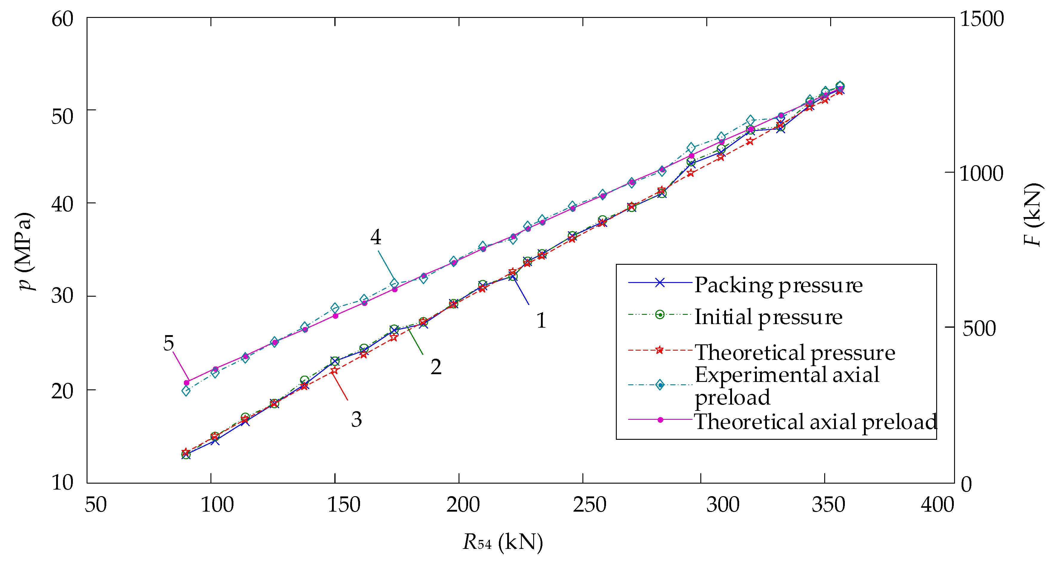
There was no mutation point in the obtained data. Therefore, the average value of the three groups of data was taken according to the loading times. Each test was loaded 25 times. The experimental data are shown in Table 1. The experimental data are compared with the theoretical analysis data, as shown in Figure 10. We can get the following results:
As can be seen from curve 1 in Figure 10, by adjusting the loading hydraulic cylinder thrust, R54, the internal pressure sealed by the subsea collet connector increases with the loading hydraulic cylinder thrust, R54.
Compare curves 1 and 2, it can be seen that, due to certain internal leakage of the cut-off valve and other equipment, a certain pressure drop will be generated after pressure maintainance. When R54 = 102 kN and initial pressure is 15 MPa, the largest pressure drop is about 0.5 MPa. All measured values are less than 5% of the current loading pressure, which meets the pressure drop requirements of the standard.
According to the comparison between curve 1 and curve 3, under the same thrust R54, 64% of the actual packing pressure value of sampling points is higher than the theoretical pressure value in 25 sets of data. The reason is that this experiment uses the leakage as the criterion, while the theoretical analysis uses no leakage as the criterion.
The experimental loading hydraulic cylinder thrust, R54, was substituted into Equation (22) for the calculation to obtain the theoretical axial preload curve 5. The experimental packing pressure (curve 1) was substituted into Equation (12) for calculation, and the corresponding experimental axial preload (curve 4) was obtained. According to the comparison between curve 4 and curve 5, there is a certain difference between the experimental and theoretical axial preload. The maximum difference occurs at the initial loading point, of which the loaded hydraulic cylinder thrust is 90 kN, the corresponding experimental axial preload is 294 kN, and the theoretical axial preload is 322.63 kN, with a difference of 8.87%. The experimental loaded hydraulic cylinder thrust, R54, is 30.61% of the axial preload, F. Taking the average value of all experimental points, it can be seen that the experimental loading hydraulic cylinder thrust, R54, is 27.76% of the experimental axial preload, F, which is close to the theoretical value (27.95%) calculated in Section 3.3, and the difference is 0.68%.

5.2.2. Experimental results of sealing width

The sealing width indentation on the spherical surface of the lens-type sealing gasket before and after the experiment is shown in Figure 11. It can be seen from Table 2 that the experimental measurement results are smaller than the theoretical analysis results, especially in the case of a small axial preload (294 kN), the deformation of the sealing surface is very small, and the theoretical sealing width is 3.30 mm. For the sealing width indentation obtained in the experiment, the deformation amount on the edge is too small, which makes it difficult for human eyes to observe. The sealing width measured by the experiment is 2.74 mm. The difference between the experimental measured result and the theoretical analysis is 17.09%. Therefore, the lower the pressure is, the lower the axial preload is and the bigger the measurement error will be.
When the axial preload is 845.04 kN, the sealing pressure is 34.6 MPa (a little higher than 34.5 MPa), the measured experimental sealing width is 5.57 mm, compared with the theoretical sealing width (5.77 mm), the difference is 3.45%. When the axial preload was 1274.88 kN, the sealing pressure was 52.2 MPa (a little higher than 51.75 MPa), the measured experimental sealing width was 7.09 mm, compared with the theoretical sealing width (7.37 mm), the difference is 3.83%.

6. Conclusions

In this article, according to the characteristics of the subsea collet connector sealing structure, a mathematical calculation method of the sealing characteristics of the non-standard metal lens-type sealing gasket is proposed, and its leakage characteristics are analyzed theoretically, then the correctness of the theoretical results is verified by experiments. The mathematical model established in this article can apply to the full-scale subsea collet connector and the lens-type sealing gasket and has a certain guiding effect in the sealing structure design of the subsea connector. The main conclusions are as follows:
The macroscopical mechanical model of the sealing contact is established, and the linear relationship between the sealing half-width and the maximum contact pressure of the lens-type sealing gasket is determined. The axial preload model of the lens-type sealing gasket under the preloading mode is established by studying the internal pressure of the sealing structure under different states.
Based on the analysis of the connector’s self-locking ability, the force transfer between the press ring, fingers, and hubs of the connector is derived, which proves that the designed structure reduces the demand for the thrust provided by the loading hydraulic cylinder, R54 = 27.95% F.
The leakage equation of the lens-type sealing gasket of the subsea collet connector is deduced based on the microscopic contact model of one-dimensional wavy surface. The analysis shows that the radial leakage of the lens-type sealing gasket is 0, and the circumferential leakage is the main leakage. The leakage rate of the sealing structure of the subsea collet connector is Qc = 1.80 × 10⁻¹⁵ mm3/s, which is far less than 1 mm3/s specified in standard ISO 21329, and meets the requirements of the leakage rate of the subsea connector. Additionally, the experiment shows that all measured hydrostatic pressure results are less than 5% of the current loading pressure, which meets the pressure drop requirements of the standard.
The hydrostatic pressure experiment of the sealing characteristics of the subsea collet connector is designed. The experimental results show that the experimental loading hydraulic cylinder thrust, R54, is 27.76% of the experimental axial preload, F, and the relative difference with the theoretical value (27.95%) is 0.68%.
According to the sealing width measurement, when the internal pressure is 34.6 MPa, the experimental and theoretical sealing widths are 5.57 mm and 5.77 mm respectively, and the difference is 3.45%. When the internal pressure is 52.2 MPa, the experimental and theoretical sealing widths are 7.09 mm and 7.37 mm respectively, and the difference is 3.83%. The experimental results are consistent with the theoretical ones.

Author Contributions

Conceptualization, F.Y. and Z.Y.; methodology, F.Y., G.W. and P.J.; validation, X.X. and F.Y.; formal analysis, F.Y. and X.X.; investigation, H.S. and Z.Y.; resources, L.W.; data curation, W.L.; writing—original draft preparation, F.Y.; writing—review and editing, X.X. and G.W.; funding acquisition, L.W. and F.Y. All authors have read and agreed to the published version of the manuscript.

Funding

This research was funded by the National Natural Science Foundation of China, grant number 5177090429; Fundamental Research Funds for the Central Universities, grant number 3072020CF0702; The School Land Integration Development Project of Yantai (development and test platform of subsea production system), grant number 2019XDRHXMPT29.

Acknowledgments

The authors gratefully acknowledge the financial support from National Natural Science Foundation of China, grant number 5177090429; Fundamental Research Funds for the Central Universities, grant number 3072020CF0702; The School Land Integration Development Project of Yantai (development and test platform of subsea production system), grant number 2019XDRHXMPT29. The authors also would like to express their gratitude to all the friends in our scientific team, who have always been helping and supporting us without a word of complaint.

Conflicts of Interest

The authors declare no conflicts of interest.

References

  1. Bai, Y.; Bai, Q. Subsea Pipelines and Risers, 1st ed.; Elsevier Science Ltd: Kidlington, UK, 2005; pp. 3–19. [Google Scholar]
  2. Zhang, J.; Gao, J.; Lin, X. Analysis of Connector Contact Failure. IEICE Trans. Electron. 2003, 102, 945–952. [Google Scholar]
  3. Payne, J.R.; Schneider, R.W. Comparison of proposed ASME rules for bolted flanged joints. In Proceedings of the International Conference on Pressure Vessel Technology, Montreal, QC, Canada, 21–26 July 1996; pp. 147–167. [Google Scholar]
  4. Feng, X.; Gu, B. Research on Leakage Model of Metallic Gasket Seal. Lubr. Eng. 2006, 31, 83–85. [Google Scholar]
  5. Feng, X.; Gu, B. Experimental Research on Leakage Model of Metallic Gasket Seals. Lubr. Eng. 2008, 33, 48–50. [Google Scholar]
  6. Zhao, H.; Chen, R.; Luo, X.; Duan, M.; Lu, Y.; Fu, G.; Tian, H.; Ye, D. Metal Sealing Performance of Subsea X-tree Wellhead Connector Sealer. Chin. J. Mech. Eng. 2015, 649–656. [Google Scholar] [CrossRef]
  7. Wei, Z.; Wang, L.; Guan, Y.; Yao, S.; Li, S. Static metal sealing mechanism of a subsea pipeline mechanical connector. Adv. Mech. Eng. 2016, 8, 1687814016654821. [Google Scholar] [CrossRef] [Green Version]
  8. Toshiyuki, S.; Kentaro, T.; Takashi, K.; Ryou, K. Finite Element Method Stress Analysis and Evaluation of the Sealing Performance in Box-Shape Flange Gasketed Connections Subjected to Internal Pressure. J. Press. Vess. Technol. ASME 2017, 139, 051202. [Google Scholar]
  9. Liu, Y.; Ji, A.; Li, Q.; Zhi, P.; Fan, X.; Xu, C. Finite element analysis on the sealing performance of the casing premium connection. Mach. Des. Manu. Eng. 2017, 46, 21–24. [Google Scholar]
  10. Yun, F.; Wang, L.; Yao, S.; Liu, J.; Liu, T.; Wang, R. Analytical and experimental study on sealing contact characteristics of subsea collet connectors. Adv. Mech. Eng. 2017, 9, 168781401770170. [Google Scholar] [CrossRef] [Green Version]
  11. Zhang, K.; Huang, H.; Duan, M.; Hong, Y.; Estefen, S.F. Theoretical investigation of the compression limits of sealing structures in complex load transferring between subsea connector components. J. Nat. Gas Sci. Eng. 2017, 44, 202–213. [Google Scholar] [CrossRef]
  12. Wang, L.; Wei, Z.; Yao, S.; Guan, Y.; Li, S. Sealing Performance and Optimization of a Subsea Pipeline Mechanical Connector. Chin. J. Mech. Eng. 2018, 31, 18. [Google Scholar] [CrossRef]
  13. Shao, Y.; Yin, Y.; Du, S.; Xi, L. A Surface Connectivity-Based Approach for Leakage Channel Prediction in Static Sealing Interface. J. Tribol. 2019, 141, 062201. [Google Scholar] [CrossRef]
  14. Lutkiewicz, P.; Robertson, D.; Pulvino, M. Establishment of Industry Standard Flange Sealing Effectiveness Measure (Leakage Rate Based) Methodology. In Proceedings of the Pressure Vessels and Piping Conference, San Antonio, YX, USA, 14–19 July 2019; American Society of Mechanical Engineers: New York, NY, USA, 2019. [Google Scholar]
  15. Wang, S.; Yao, X.; Yang, H. The heat conduction model and leakage characterization of the sealing interface. Int. J. Therm. Sci. 2019, 145, 106027. [Google Scholar] [CrossRef]
  16. Li, S.; Qian, C.; Li, S.; Li, Q.; Liao, H. Study of sealing mechanism of gas-liquid miscible backflow pumping seal. Tribol. Int. 2020, 142, 105974. [Google Scholar] [CrossRef]
  17. Wu, H.; Shen, S.; Chen, R.; Zhou, A. Three-dimensional numerical modelling on localised leakage in segmental lining of shield tunnels. Comput. Geotech. 2020, 122, 103549. [Google Scholar] [CrossRef]
  18. Zhu, H.; Li, D.; Pu, H.; Wang, L.; He, Y.; Bu, Y.; Che, D. Experimental and Numerical Investigations on the Local Direct Leakage Process of Rotary Regenerative Air Preheater. Appl. Sci. 2020, 10, 1523. [Google Scholar] [CrossRef] [Green Version]
  19. Menga, N. Rough frictional contact of elastic thin layers: The effect of geometrical coupling. Int. J. Solids Struct. 2019, 164, 212–220. [Google Scholar] [CrossRef]
  20. Menga, N.; Afferrante, L.; Demelio, G.P.; Carbone, G. Rough contact of sliding viscoelastic layers: Numerical calculations and theoretical predictions. Tribol. Int. 2018, 122, 67–75. [Google Scholar] [CrossRef]
  21. Rajeev, M.; Sheril, M.; Erik, H. Analysis of contact pressure distribution on 3-bolt self-energized connector seals. In Proceedings of the 2009 ASME Pressure Vessels and Piping Conference, Prague, Czech Republic, 26–30 July 2009; pp. 71–79. [Google Scholar]
  22. Johnson, K. Contact Mechanics; Cambridge University Press: Cambridge, UK, 1987; pp. 12–119, 451–481. [Google Scholar]
  23. Valentin, L.P. Contact Mechanics and Friction: Physical Principles and Applications; Springer: Berlin/Heidelberg, Germany, 2010; pp. 30–74. [Google Scholar]
  24. Liu, P.; Zhao, H.; Huang, K.; Chen, Q. Research on normal contact stiffness of rough surface considering friction based on fractal theory. Appl. Surf. Sci. 2015, 349, 43–48. [Google Scholar] [CrossRef]
  25. Pan, W.; Li, X.; Wang, L.; Mu, J.; Yang, Z. A loading fractal prediction model developed for dry-friction rough joint surfaces considering elastic-plastic contact. Acta Mech. 2018, 229, 2149–2162. [Google Scholar] [CrossRef]
  26. Robbe-Valloire, F.; Prat, M. A model for face-turned surface microgeometry: Application to the analysis of metallic static seals. Wear 2008, 264, 980–989. [Google Scholar] [CrossRef]
  27. Letalleur, N.; Plouraboué, F.; Prat, M. Average flow model of rough surface lubrication: Flow factors for sinusoidal surfaces. J. Tribol. 2002, 124, 539–546. [Google Scholar] [CrossRef]
  28. Polycarpou, A.A.; Etsion, I. A model for the static sealing performance of compliant metallic gas seals including surface roughness and rarefaction effects. Tribol. Trans. 2000, 43, 237–244. [Google Scholar] [CrossRef]
  29. Liao, C.; Xu, X.; Fang, H.; Wang, H.; Man, M. A leakage model of metallic static seals based on micromorphology characteristics of turning flange surface. Ind. Lubr. Tribol. 2015, 67, 572–581. [Google Scholar] [CrossRef]
  30. Geoffroy, S.; Prat, M. On the leak through a spiral-groove metallic static ring gasket. J. Fluids Eng. 2004, 126, 48–54. [Google Scholar] [CrossRef]
  31. Karniadakis, G.; Beskok, A. Micro flows: Fundamentals and simulation. Appl. Mech. Rev. 2002, 55, B76. [Google Scholar] [CrossRef]
  32. Francois, R.V. Statistical analysis of asperities on a rough surface. Wear 2001, 249, 401–408. [Google Scholar]
  33. ISO21329. Petroleum and Natural Gas Industries—Pipeline Transportation Systems—Test Procedures for Mechanical Connectors; International Organization for Standardization: Geneva, Switzerland, 2004. [Google Scholar]
  34. API SPEC 6A. Specification for Wellhead and Tree Equipment; American Petroleum Institute: Washington, DC, USA, 2018. [Google Scholar]
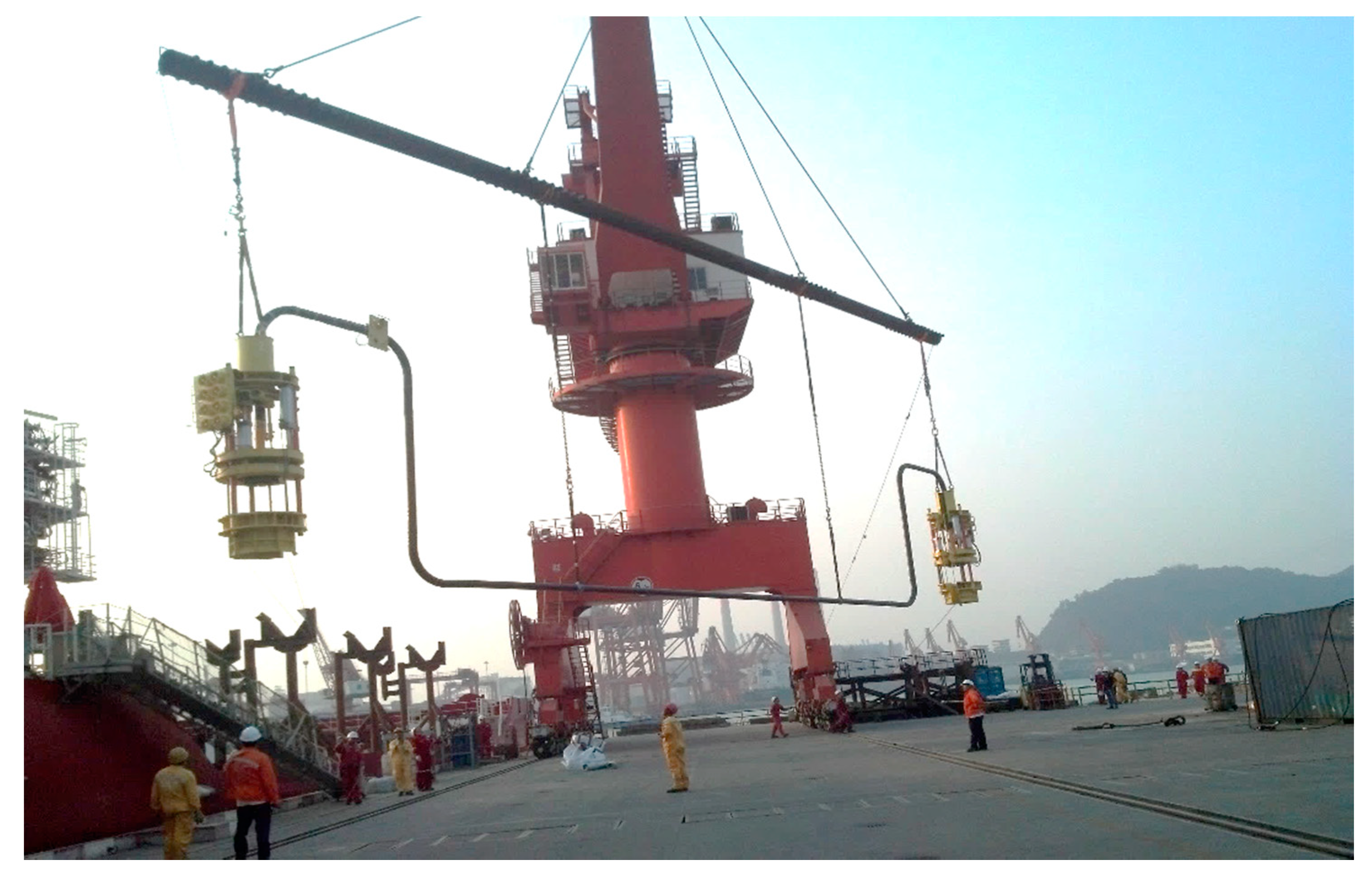
Figure 1. Practical application of the subsea collet connectors (two subsea collet connectors work together).
Jmse 08 00444 g001
Figure 2. Integral structure of subsea collet connector. (a) Installation tool; (b) Connectors.
Jmse 08 00444 g002
Figure 3. Force of the sealing gasket in preloading mode.
Jmse 08 00444 g003
Figure 4. Contact principle diagram of the sealing gasket. r is the radius of the sealing sphere; a is the sealing half-width.
Jmse 08 00444 g004
Figure 5. Schematic of force transmission diagram of the subsea collet connector sealing structure. 0-sealing gasket, 1-upper hub, 2-base hub, 3-finger, 4-press ring, 5-loading hydraulic cylinder. (a) The force of the press ring in operating mode; (b) The force of the preloading mode.
Jmse 08 00444 g005
Figure 6. Schematic of the turning surface microstructure.
Jmse 08 00444 g006
Figure 7. Contact schematic of the one-dimensional wavy surface. (a) The surface of the synthesized metal flat gasket; (b) The contact pressure of the surface completely compressed to a smooth state; (c) Discontinuous contact. H is the amplitude; q ¯ is the mean contact pressure; q* is the amplitude of contact pressure; O is the contact center; b1 is the actual sealing width; b2 is the width of the leakage channel.
Jmse 08 00444 g007
Figure 8. Lens-type sealing gasket micro-contact.
Jmse 08 00444 g008
Figure 9. Schematic diagram of the hydrostatic internal pressure experiment. (a) Experimental scheme; (b) Photograph of the experimental device.
Jmse 08 00444 g009
Figure 10. Comparison of hydrostatic pressure experiment results.
Jmse 08 00444 g010
Figure 11. Indentations comparison.
Jmse 08 00444 g011
Table 1. Hydrostatic pressure experiment data.
Loading TimesR54
(kN)
Initial Pressure (MPa)Packing Pressure (MPa)Loading TimesR54
(kN)
Initial Pressure (MPa)Packing Pressure (MPa)
19013.013.01423434.634.6
210215.014.51524636.536.5
311417.016.51625838.238.0
412618.518.51727039.539.5
513821.020.51828241.041.0
615023.023.01929444.544.2
716224.424.22030645.845.5
817426.526.32131847.947.8
918627.327.02233048.248.0
1019829.229.22334250.850.5
1121031.231.12434851.851.5
1222232.132.12535452.552.2
1322833.833.8
Table 2. Comparison of the sealing width of the experimental and analytical results.
Axial Preload (kN)Pressure (MPa)Experimental Sealing Width (mm)Analytical Sealing Width (mm)Difference (%)
294.0013.02.743.3017.09
354.1314.53.133.5110.86
402.9816.53.443.778.85
452.0018.53.784.026.09
500.6720.53.984.276.70
561.7323.04.214.557.56
591.0424.24.394.696.38
642.3326.34.664.925.26
659.4227.04.684.996.28
713.1529.24.965.235.08
759.5631.15.135.425.36
783.9832.15.215.525.64
825.5033.85.335.696.33
845.0434.65.575.773.45
891.4436.55.695.954.42
928.0838.05.846.14.21
964.7139.56.016.243.65
1001.3441.06.096.384.51
1079.5044.26.186.677.34
1111.2545.56.416.795.55
1167.4247.86.676.994.58
1172.3148.06.707.014.39
1233.3650.56.997.233.26
1257.7951.57.017.314.13
1274.8852.27.097.373.83