Article

Structural Safety Analysis for an Oscillating Water Column Wave Power Conversion System Installed in Caisson Structure

1
Department of Marine Environment and Engineering, National Sun Yat-sen University, Kaohsiung 804 Taiwan
2
Harbor and Marine Technology Center, IOT of MOCT, Taichung 435, Taiwan
*
Author to whom correspondence should be addressed.
J. Mar. Sci. Eng. 2020, 8(7), 506; https://doi.org/10.3390/jmse8070506
Submission received: 22 June 2020 / Revised: 6 July 2020 / Accepted: 7 July 2020 / Published: 9 July 2020
(This article belongs to the Special Issue Waves and Ocean Structures)

Abstract

:
In this study, an alternative way, a so called caisson based type of oscillating water column (OWC) wave energy converting system was proposed to capture and convert wave energy. Since the caisson structure is constructed to protect the coastal line or ports, it is important to know if a built-in associated OWC system will be a burden to affect the safety of the structure or it is safe enough to work appropriately. In this study, three steps of structural analysis were performed: firstly, the analysis for the structural safety of the whole caisson structure; secondly, performing the mechanic analysis for the chamber of the associated OWC system; and finally, performing the analysis for the wave induced air-pressure in the chamber under the design conditions of a local location during the wave-converting operation. For the structural safety analysis, a typical structural model associated with caisson breakwater was built and analyzed while the shape of the structure, material applied to the construction, and associated boundary conditions were all set-up according to the wave and structures. The motion and the strain distribution of the caisson structure subjected to designated waves of 50-year return period were evaluated and compared to the safety requirement by the code. For the analysis of the energy converting performance, a numerical method by using a theorem of unsteady Navier–Stokes equations in conservation form was used to analyze the proposed OWC model when the structure subjected to an incident wave of a 10-year return period.

1. Introduction

1.1. Development of an Oscillating Water Column (OWC) Wave Energy Converter

During late 1980s and then 1990s, intensive studies for a wave-power converting system were performed. However, it was not until 1991 when a combination with breakwater system was firstly studied in Japan [1]. In that study, not only were experimental tests performed in the laboratory but also an on-site, full-scale structure was built and tested. Many valuable data were firstly acquired resulting in an encouraging way for the OWC wave power converting system. Important conclusions include the efficiency of power that can be obtained from the conversion system, the estimated direct cost for a system of comparable size and scale, and a range of dimensional ratios between the air chamber and the wavelength. The most important one was that the combination for a breakwater with the wave-power converting system would not affect the function of the breakwater. However, this conclusion related to the structural safety was only based on an overall estimation of the mass of the caisson breakwater against the wave-loading, without considering the detailed variation of the caisson with the installation of an OWC converting system, in which additional chambers with walls and slabs were built. The other difficulty was that even though the study from Goda et al. [1,2] is invaluable and pioneering, it is too hard and too costly to be repeated for an on-field experiment. It was also too confined by many local factors for a special case to apply to the caisson breakwater in other locations with different environmental conditions.
Until now, researches on the OWC wave energy converting system are still in a very active status. Some are on the improvement of the mechanism of energy harvest such as to change the shape of traditional OWC system into a U-OWC [3] or a so called BBDB-OWC by using a backward-bent duct buoy [4,5]; some are focused on the efficiency of turbine performance for outflow and inflow motions [6]; investigations on the wave-height and power taking-off damping effect are also carried out experimentally and numerically [7]; some are focused on the performance of the air-chamber [8], where the effect of neglecting the air compressibility has been studied showing that an experimental test model scaled down to 1/50 may result in an overestimation of up to 15% for the air pressure in the OWC chamber.
Since the caisson structure is constructed to protect the coastal line, it is important to know if a built-in associated OWC system will be a burden to affect the safety of the structure. Even though, studies focusing on the structural safety of an OWC wave energy converter are attractive to researchers, references related to this matter are mostly focused on the exerting forces and pressures rather than the response of structure itself [9,10,11,12,13]. This is indicated in a model to estimate forces acting on an OWC chamber in a caisson breakwater [9], where horizontal forces on the front (curtain) wall and the rear (in-chamber) wall are predicted. It also mentioned that unlike a conventional caisson breakwater, vertical forces acting on the caisson chamber ceiling will have considerable effect on sliding and overturning characteristics of the breakwater structure. A first OWC device embedded into a breakwater was installed in 2008 at the Port of Mutriku. Storms hit it in December 2007, March 2008, and January 2009, resulting in structural damage to both the frontal wall and roof of four chambers [14]. Fortunately, the OWC power plant was not yet under operation because the operational license had not been granted, but still it reflected that no matter how carefully the exerting forces could be calculated, the response and safety of the chamber structure was the essential matter for an OWC wave energy converting system.
Some other studies also were concerned about the safety of operation of an OWC conversion system but only very few focused on the structural safety [15]. That study considered the safety for an OWC integrated into a bottom-sitting pile structure (an OWC pile). The authors examined the wave loads on an OWC pile, which included the viscous loads and lateral loads and then safety-loading for a bottom-sitting pile design that could then be estimated. The issue of structural safety was not only essential to the operational of the system but also important to the maintenance of the system during the operation for the inspection and damage investigation that may cost a considerable fortune [16].

1.2. Objectives of the Study

In this study, by following the findings of Goda et al. and the contemporary studies [10,11], a series of studies were performed by adopting, but upgrading, a similar system, the so called the caisson based OWC type wave energy converter for green energy developments. The analysis of structural safety were performed: firstly, the analysis for the structural safety of the caisson structure and the associated built-in OWC chambers and secondly, the safety of the chamber during the wave-converting operation in the associated OWC system located at a specific water area such as Kaohsiung, Taiwan, subjected to local environmental conditions. For the structural safety analysis, usually two safety issues needed to be clarified. The first safety analysis was the overall estimation of structural resistant ability against the environmental loadings such as the one performed in Goda’s study [1]. During the analysis, the whole structure was assumed to be a rigid body and therefore, the weight of the structure was the only matter to resist both the shear force and the overturning moment induced by the wave-pressure on the structure while the exertion of soil and water were both taken into account. Because this kind of analysis is more related to the weight of the structure (usually a big mass-structure like a caisson breakwater), compared to the breakwater, the weight of the associated OWC chambers, which are relatively small, will still increase the total weight of the whole structural system of the breakwater. Therefore, in this study the rigid body analysis will be skipped, and we instead focus on the second part, the structural safety estimation by using more sophisticated structural analytical method for both the whole structure and the OWC chambers. The second safety analysis was related more to a flexible type structure so that the resistance of the structure to the external loadings was not only based on the weight of the structure. The elasticity and strength of material and member related resistance must be taken into account for the structure, such as the one in this study where a traditional caisson breakwater structure was transformed with a built-in chamber of the OWC converting system. Whether the change in the structure will cause an additional safety related problem to the OWC system or the caisson breakwater must be estimated.
In this study, a typical structural model was built and analyzed while the shape of the structure, material applied to the construction and associated boundary conditions were all set-up according to the wave and structural design. The examination for the structural safety includes two parts, namely, the overall structural safety of the caisson structure with associated OWC chambers and the mechanic behavior of the chamber related structural members. In the analysis for the whole breakwater, the deformations and strains of the caisson will be examined. For the analysis of the OWC structural members, the deformations and strains of the structural members of OWC-chamber including the front curtain wall and ceiling slab built in the breakwater caisson structure subjected to designated incident waves were analyzed and compared to the safety requirement for the allowance of material deformation. The applied incident wave was based on a general design code and set as a storm of 50 years return period.
Since a more detailed study for the performance of a similar system has already been presented in a related paper [17,18], the analysis of energy conversion performance in this study will focus on the influence of the air pressure on the air-chamber induced from the heaving wave motion. A numerical method by using a theorem of unsteady Navier–Stokes equations in conservation form is used to analyze the proposed OWC model. A proposed case built-in along a breakwater structure located in a local harbor was applied for a performance study to examine the feasibility of the OWC system in the harbor. The analysis was focused on the correspondence between the wave motion and the variations of air-pressures inside the air-chamber. A comparison with Goda’s result was made before carrying out the performance analysis to verify the workability of the numerical method.
It was noticed that the wave force applied to the structural safety analysis was larger than the one applied to the performance analysis. This was because the durability requirement for the structural design enforces that a more strict environmental condition be considered, while for the wave energy converting performance analysis, a normal regular wave would be enough to drive the device of an OWC converter. Therefore, a wave due to a storm of 50 years return period was applied to the structural safety analysis and on the other hand, a wave based on a storm of 10 years return period was applied for the performance analysis.
During the structural safety analysis, it was found that for the overall structural safety of the caisson structure with associated OWC chambers, the deformation of the whole structure was safe when subjected to a storm-wave of 50-year return period. However, during the structural analysis for the local behavior of the OWC air-chamber, it was found that a more strict design criteria needed to be applied to the members of the chambers if the chamber was to sustain a storm-wave of 50-year return period. During the analysis for the operational performance of the OWC converting system attached to the caisson structure, it was found that the air-pressure induced by the heaving waves in the chamber could reach as high as 31.5 MPa when the OWC was subjected to a wave of 10-year return period.

2. Analytical Model and Environmental Forces

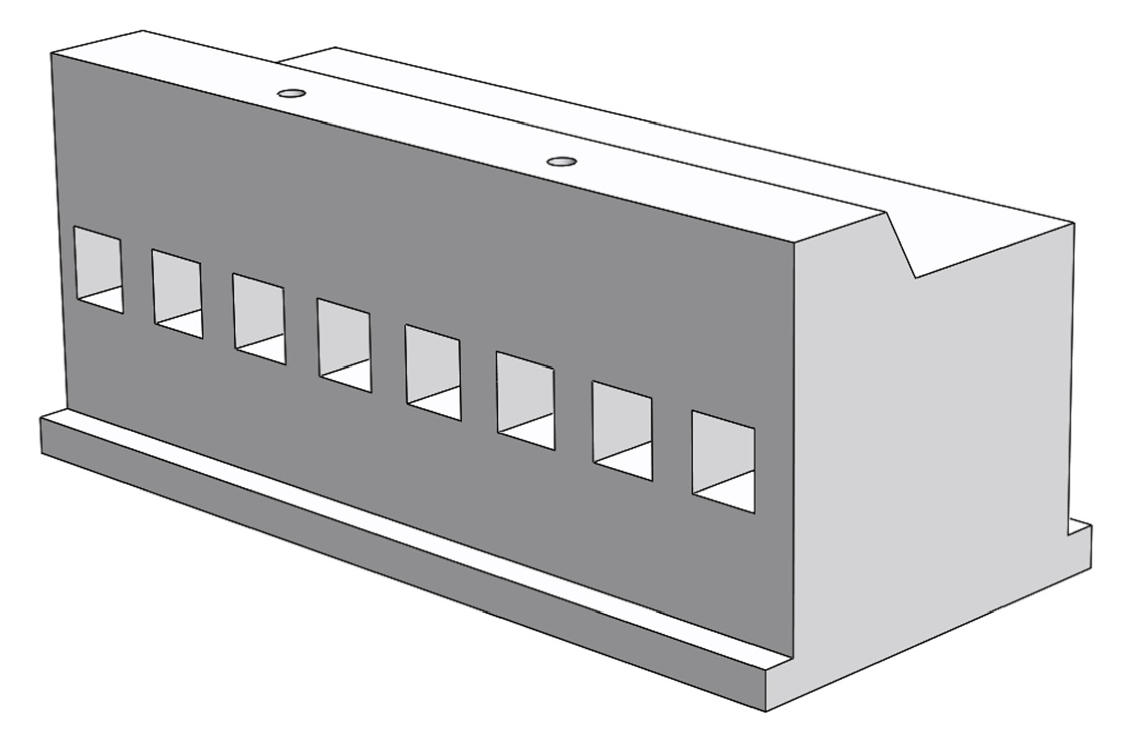
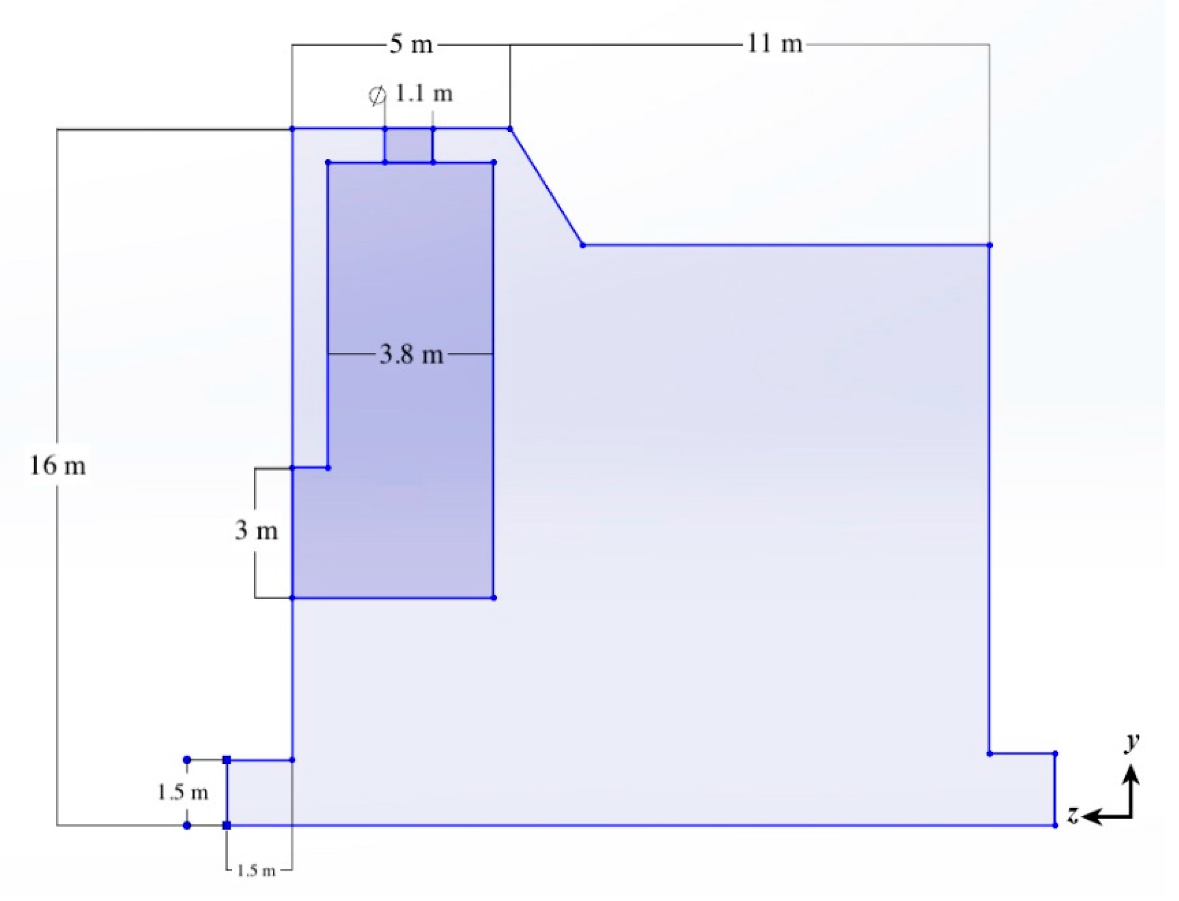
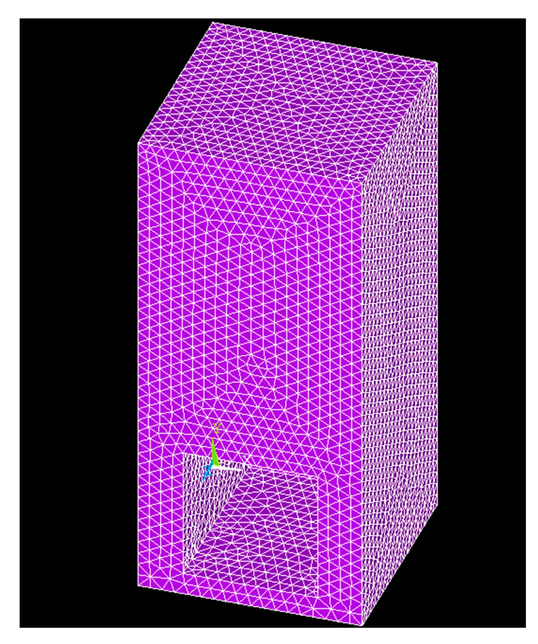
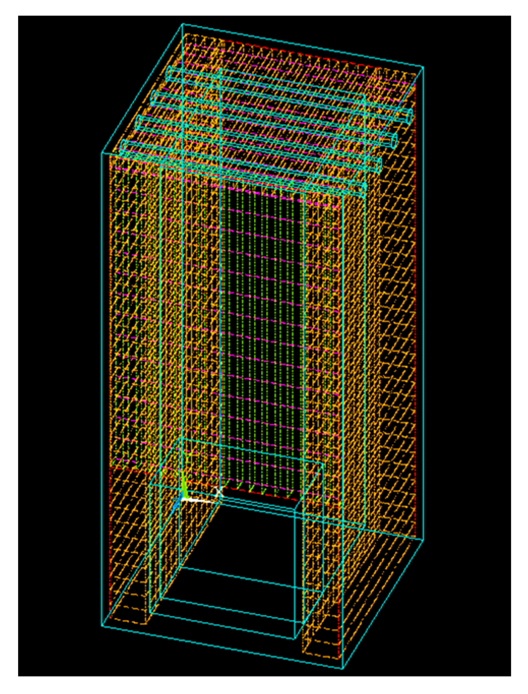
2.1. Analytical Model of the Structure

In this study, a typical caisson structure for the breakwater and coastal protection located in water of 16 m depth was designed with the installation of accommodated OWC system. As shown in Figure 1, a schematic 3-D view of the caisson structure associated with an OWC wave energy converting system is shown, where the front side shows the square gates of air-chambers of the OWC system. Figure 2 shows the side-view of the caisson structure, where a chamber of rectangular shape for the OWC is located in the front part of the structure. Dimensions for the structure and the size of chamber are also shown in the figure.

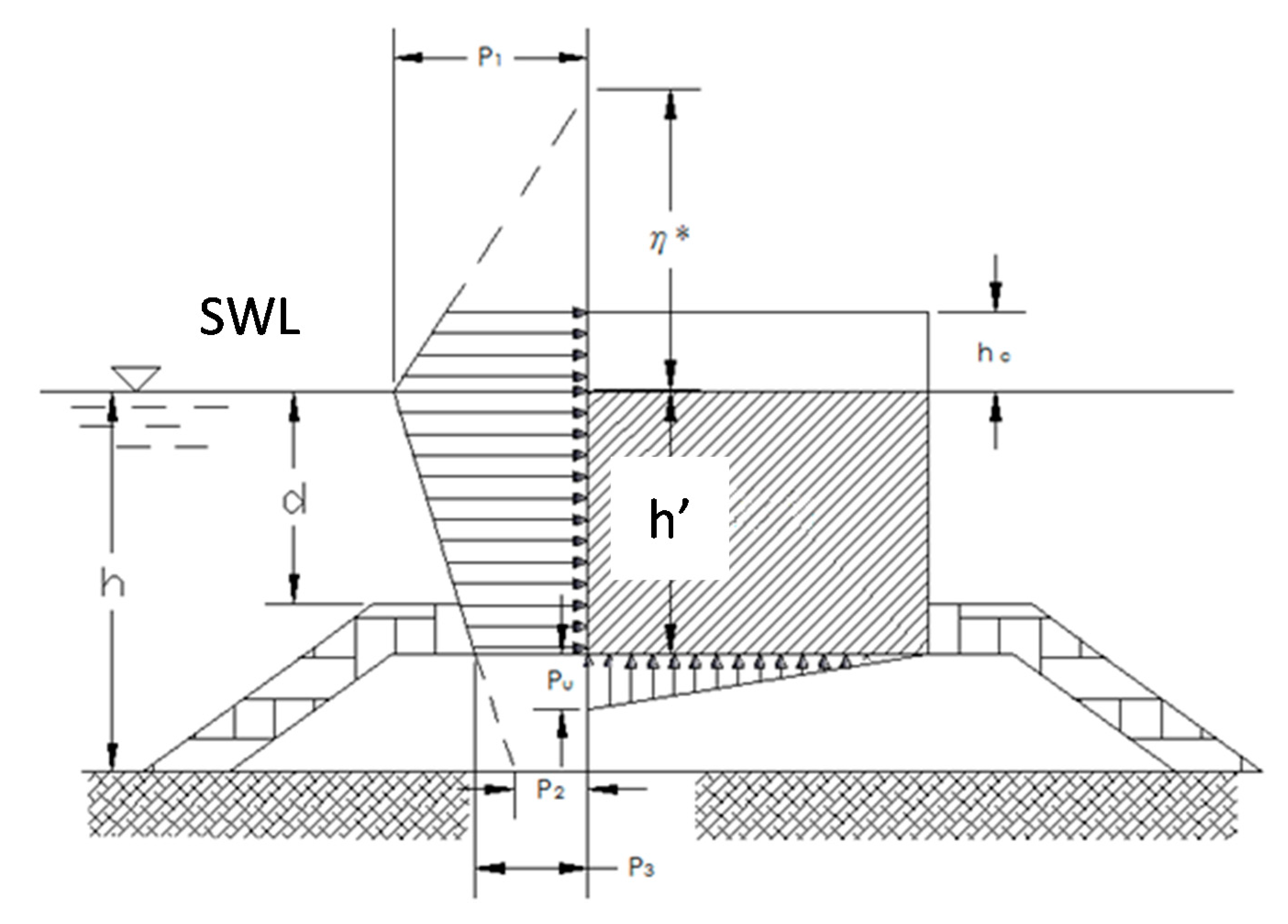
2.2. Environmental Forces

For the environmental conditions in this study, a storm of 50 years return period at the proposed location was applied to the analysis of which the wave height H = 1.8Hd was 9.5 m and the corresponding period T was 10 s and Hd was the designed wave height for the breakwater of caisson structure. The incident wave was assumed to propagate in the direction normal to the front face of the caisson structure. The exerting pressure on the caisson breakwater then can be calculated based on the properties of the design-wave as prescribed.
For the analysis of structural safety, first of all, the exerting pressures from the environment including wave, water, soil, and reaction forces were all accounted and estimated. As was shown in Figure 3, it is a schematic drawing for the exerting forces around the caisson structure, which was modified based on Goda’s method [19]. The calculation procedure is presented as follows:
(1) Determine the wave pressure at the still water level (SWL) as
P 1 = 1 2 ( 1 + cos β ) ( α 1 + α 2 c o s 2 β ) ω 0 H d
where parameter β is the angle of incident wave to the direction normal to the caisson structure, while α1 and α2 are parameters presented as
α 1 = 0.6 + 1 2 [ 4 π h L sinh 4 π h L ] 2
and
α 2 = m i n [ ( h b d 3 h b ) ( H d d ) ,   ( 2 d H d ) ]
The dimension related parameters are shown in Figure 3 such as: h the water depth to the sea bottom and d the water depth to the surface of rubble-rump, while L is the designed wave length and hb is the water depth at a distance of five times of significant wave-height away from the caisson structure.
(2) Determine wave pressure at the sea bottom level as
P 2 = P 1 cosh ( 2 π h L )
(3) Determine the wave pressure at the toe of the caisson as
P 3 = α 3 P 1
where the parameter α3 is presented as
α 3 = 1 h h [ 1 1 cosh ( 2 π h L ) ]
The dimensional parameter h’ is the submerged depth of the caisson.

3. Mechanic Analysis of Structural Safety

As mentioned in the introduction, the rigid-body analysis for the caisson structure would not be considered, that being the resistant capability from the weight of the caisson structure against the overturning moment and the sliding resistance of the structure to the horizontal wave forces. For the analysis of structural safety, the most important issue was that the stress distribution of the structure would not exceed the designed strength of the material or the strain induced from the deformation would not exceed the strain limit of the material when subjected to wave and other environmental forces. Therefore, in this study a strain analysis was performed to examine if the caisson structure was safe, along with the constructional material, when additional chambers of an OWC wave energy converter were built in, and located right at, the front side of the caisson structure facing the incident wave directly. In order to know better the structural safety, two parts of structural analysis were performed, these included the first part, a global analysis of the whole structure of caisson breakwater subjected to wave forces, and the second part, a local analysis focused on the deformation behavior of the additional chamber of an OWC wave energy conversion system.

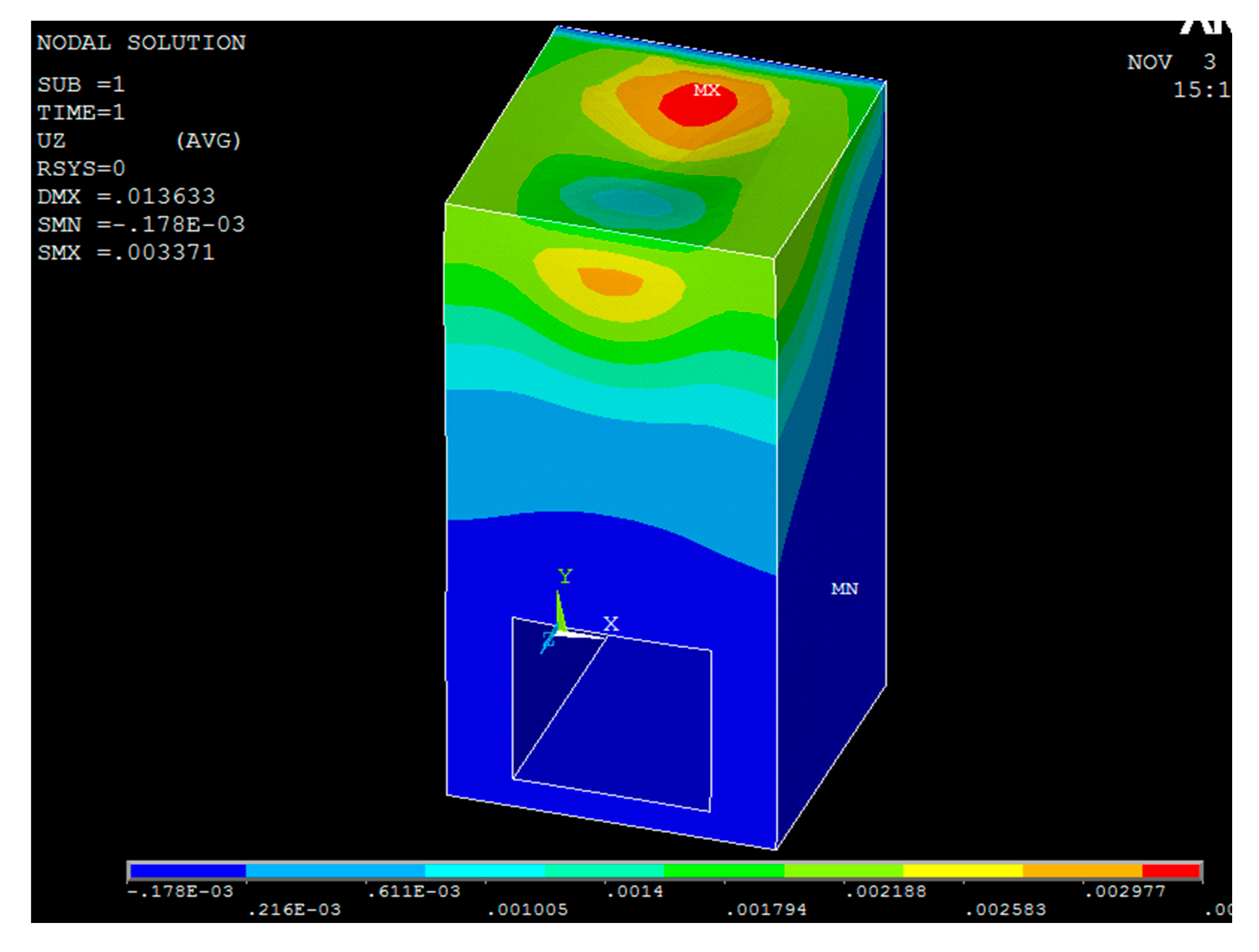
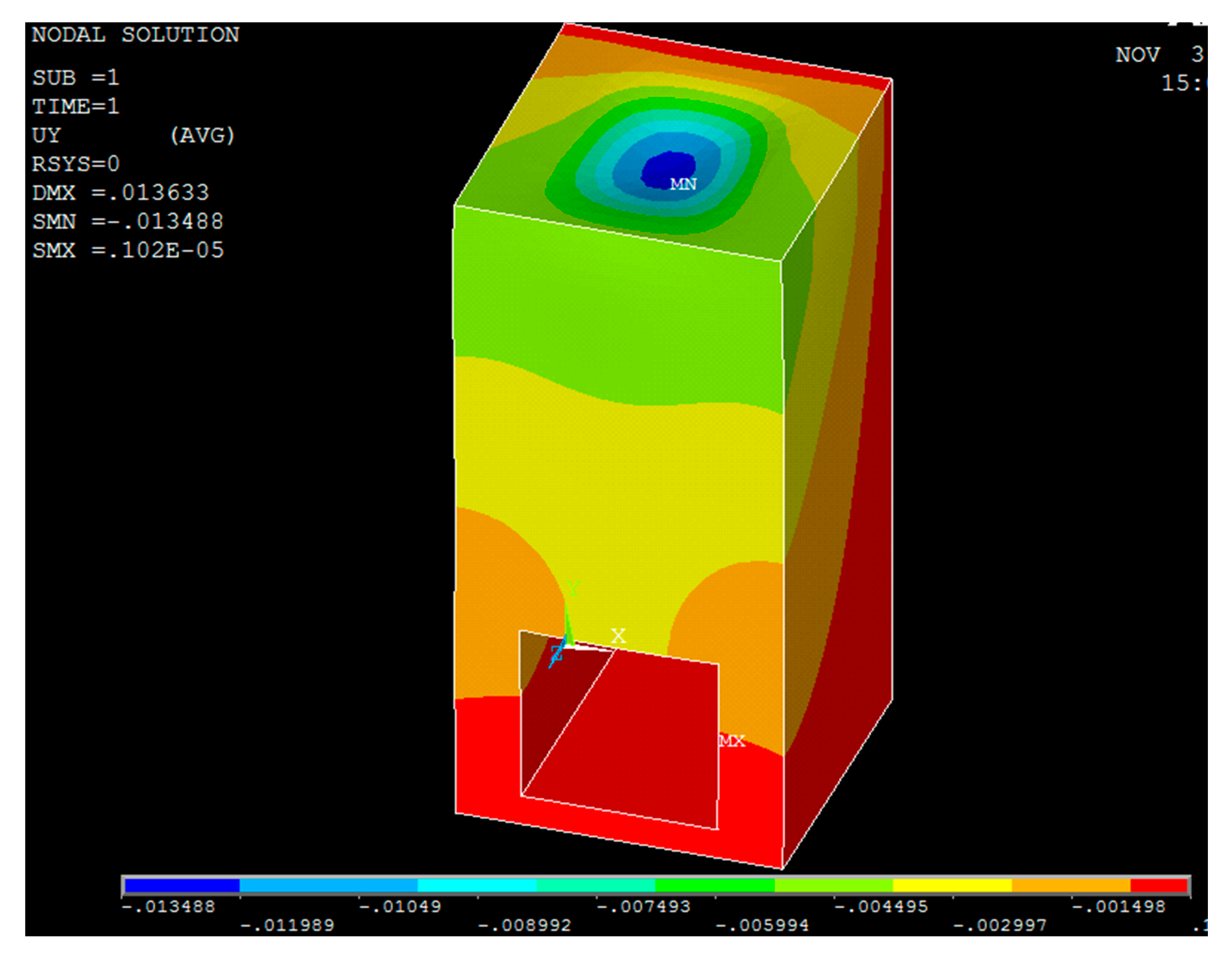
3.1. Global Structural Analysis

For the global structural analysis, the object was to examine the global deformation of the caisson structure and find the parts that may have been subjected to severe damage or large strain. After obtaining the global deformation distribution for the whole structural system, a local analysis could be performed and a more detailed investigation carried out through the structural members of the chamber including the walls between chambers, ceiling panels on the top of chamber, and the curtain walls that normal to the direction of incident waves.
The wave forces exerting on the front face of the caisson structure was in a form of pressure distribution, as P1, P2, and P3, corresponding to various levels of depth of the caisson breakwater located in the water, which are shown in Figure 3, which can be obtained from Equations (1), (4), and (5). After obtaining the wave forces exerting on the caisson structure as was shown in Figure 4, a numerical tool for the solid mechanics of well-known ANSYS was applied and the conditions including wave forces, soil pressure, and material properties were all determined. The material for the caisson structure was reinforced concrete with material properties as the designed strength of concrete: fc = 350 (kgf/cm2), elastic modulus of concrete: Ec = 30 (kN/mm2), and the elastic modulus for the steel: Es = 290 (kN/mm2) according to the ACI code for the structure exposed to an environment with chloride (marine environment) [18].
For the global structural safety analysis, a distribution of strain over the whole caisson breakwater was examined firstly and after that then a more detailed analysis on the material strength of reinforced concrete was performed for the air chamber of the OWC converter attached to the caisson breakwater. It was noticed that for the global structural analysis, since the breakwater structure is in a long and slender shape, an analytical strategy of plane strain could be applied so that only the cross section of a unit-length caisson breakwater would be analyzed and the mechanical behavior of the other sections would be assumed to be similar if the environmental conditions were similar. Even though a three-dimensional analysis could also be applied, the results would be similar to each other. Therefore, the analysis was focused on the deformations and variation of strain of the cross section.
After the analysis of global structural system, Figure 5 shows the deformation of the caisson structure, which deforms along with the direction of exerting incident waves, the weak transverse direction for a breakwater. As is observed in the analytical results, the deformation varied along with the height of the structure while the largest deformation occurred near the top of the structure in the front side, which happened to be the location of the OWC chambers. In the lower part of the caisson, the deformation was quite small, even not observable because the loading was concentrated on the higher part, as shown in Figure 3, especially for the part of structure on the still water level (SWL), where the wave action was the largest, while the cross section of the caisson structure above the water level reduced gradually. This is the reason why the largest deformation occurred near the top of the structure of the front side in the global structural analysis.
The largest deformation obtained from the analysis was 0.162 mm, which was small under the loading forces calculated for this study. Compared to the corresponding dimension of the caisson breakwater, which was 16.0 m, the strain corresponding to the deformation can be calculated as 0.01 × 10—3, which is much smaller than the strain allowance for a concrete material 0.003. However, because the location of the largest deformation was at the tip corner of the top, where the chamber of the OWC converter is built-in, a further study of the front wall of the chamber revealed that the strain corresponding to the transverse deformation was close to the allowance of the concrete material. The largest strain that occurred in the front wall was 0.00027 in terms of the thickness 0.60 m of the front wall of the chamber, as shown in the schematic drawing of Figure 2. It is one order smaller than the maximum strain (0.003) allowed for concrete material from the global structural deformation analysis. Therefore, for the global structural analysis of the caisson structure combined with an OWC wave energy converting system, it is quite safe.

3.2. Structural Analysis for the Chamber of OWC Converter

As the second part for the safety analysis, a study based on the loading and deformation of the analysis of the whole structure as discussed in previous section was performed correspondingly for the air-chamber of the OWC system located in the front side of the caisson structure. Because the shape of the structure was no longer a long and slender type, a three-dimensional analysis needed to be applied and a more sophisticated solid element was utilized in the finite element numerical analysis, which included the properties of the material that must be refined and the detailed dimensions of the structural member.
On the side view of the caisson breakwater structure, the chamber of OWC system can be observed as the darker part in Figure 2, and then the OWC chamber is framed-out and redrawn as a 3-dimensional view in Figure 6. The dimension of the chamber is also shown in figures, where Figure 2 is the dimension of the chamber for the study in side-view while Figure 6 presents a detailed dimension for structural members in the chamber such as the side wall, front curtain wall, and ceiling-slab of the air-chamber. It was noticed that during the mechanic analysis for the OWC air-chamber, the orifice for in/output air was not considered for the structural safety study because the analysis focused on the response of the structure in terms of both the deformation of the structural member, and the material capacity to examine if the strain induced from extreme deformation exceeded the material capacity.
Before performing the analysis, the analytical model was divided into meshes and nodes for the structural members of the chamber. Typical meshes for the 3-D solid-element of tetrahedron type was applied and is presented in Figure 7. The arrangement of the steel reinforcement in the concrete is also presented in Figure 8. A corresponding beam element for the steel material was also applied in the structural analysis.
Results obtained from the structural analysis include the deformation distribution and corresponding strains for the chamber of OWC wave energy converter. As was shown in the global structural analysis, the deformations in the transverse direction (as the z-direction shown in Figure 6) of the caisson breakwater was the critical issue because it was related to structural safety. However, for the chambers built in an OWC converter, responses in both the horizontal transverse direction (z-direction as shown in Figure 6) and vertical transverse direction (y-direction) were essential to the structural safety of the chamber. This is because the chamber is like an empty box that was subjected to deformations all around the walls and ceiling slabs. The x-direction for the breakwater was an in-plane direction (the axis along the layout of the breakwater) that was the strong-direction subjected to smaller loads since the wave forces exerted mostly on the transverse direction (z-direction), but for the air-chamber, the x-direction was the out-of-plane direction for the side wall, of which the deformation was also critical to the structural safety.

3.2.1. Transverse Deformation for the front Curtain-Wall

As is shown in Figure 9, this is the deformation distribution in the transverse z-direction for the OWC air-chamber without an opening orifice. The color of the contour represents the seriousness of the deformation in which both the red and blue colors indicate a larger deformation corresponding to an opposite direction each other. In Figure 9, even though the largest deformation, namely, 0.003371 m, appears at the top panel of the ceiling, relative to the dimension in the z-direction 5.0 m, the corresponding strain will be 0.000742, which is much smaller than 0.003, the maximum allowed strain in concrete structure. However, the panel of the front curtain wall was normal to the transverse deformation and therefore, the strain of the curtain wall in the z-direction (out-of-plane) would be critical to the structural safety. The largest deformation of the curtain wall is about 0.0027 m and relative to the thickness 0.6 m of the wall, as shown in Figure 6, the corresponding largest strain is 0.0045, which is slightly larger than the strain capacity of a concrete material 0.003.

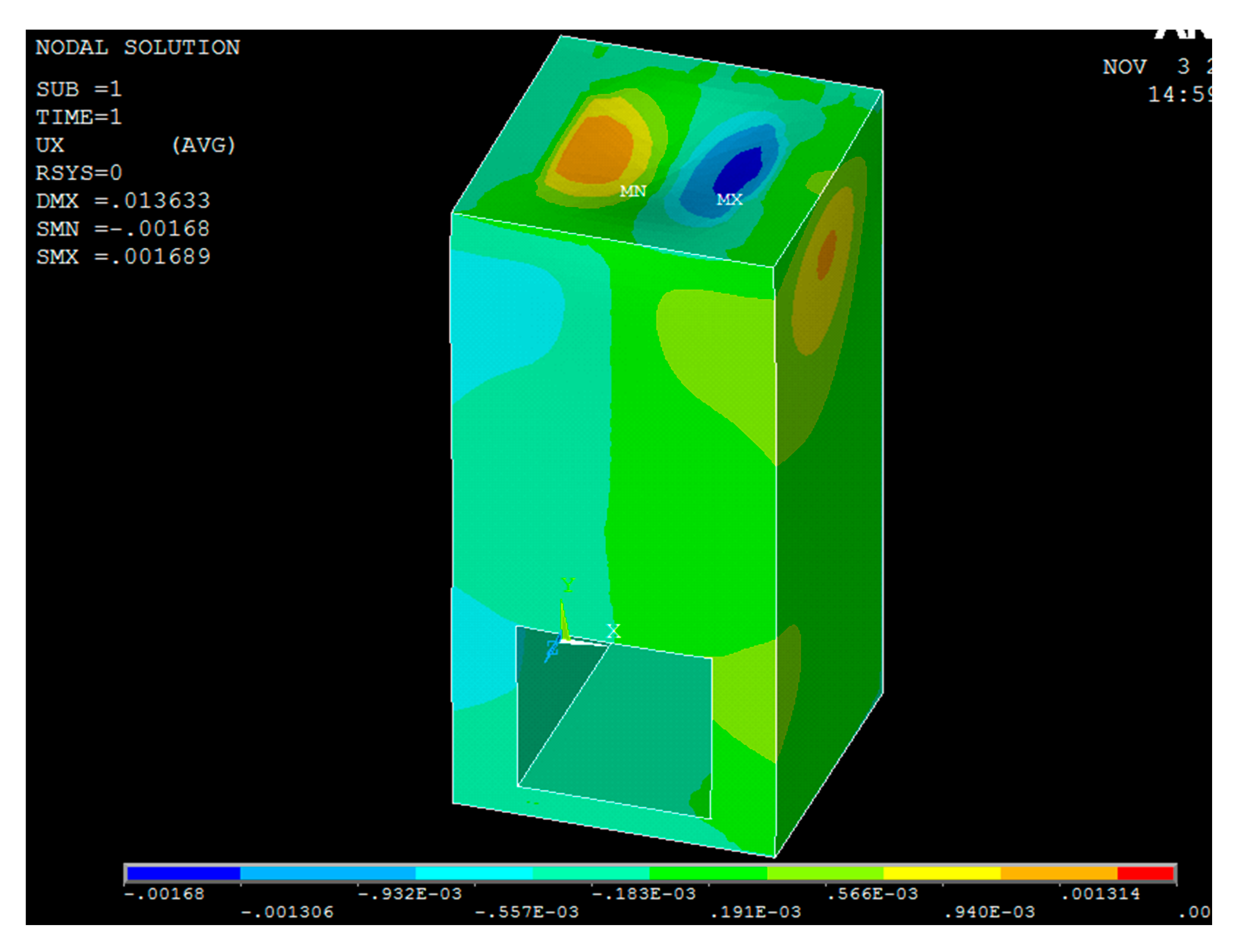
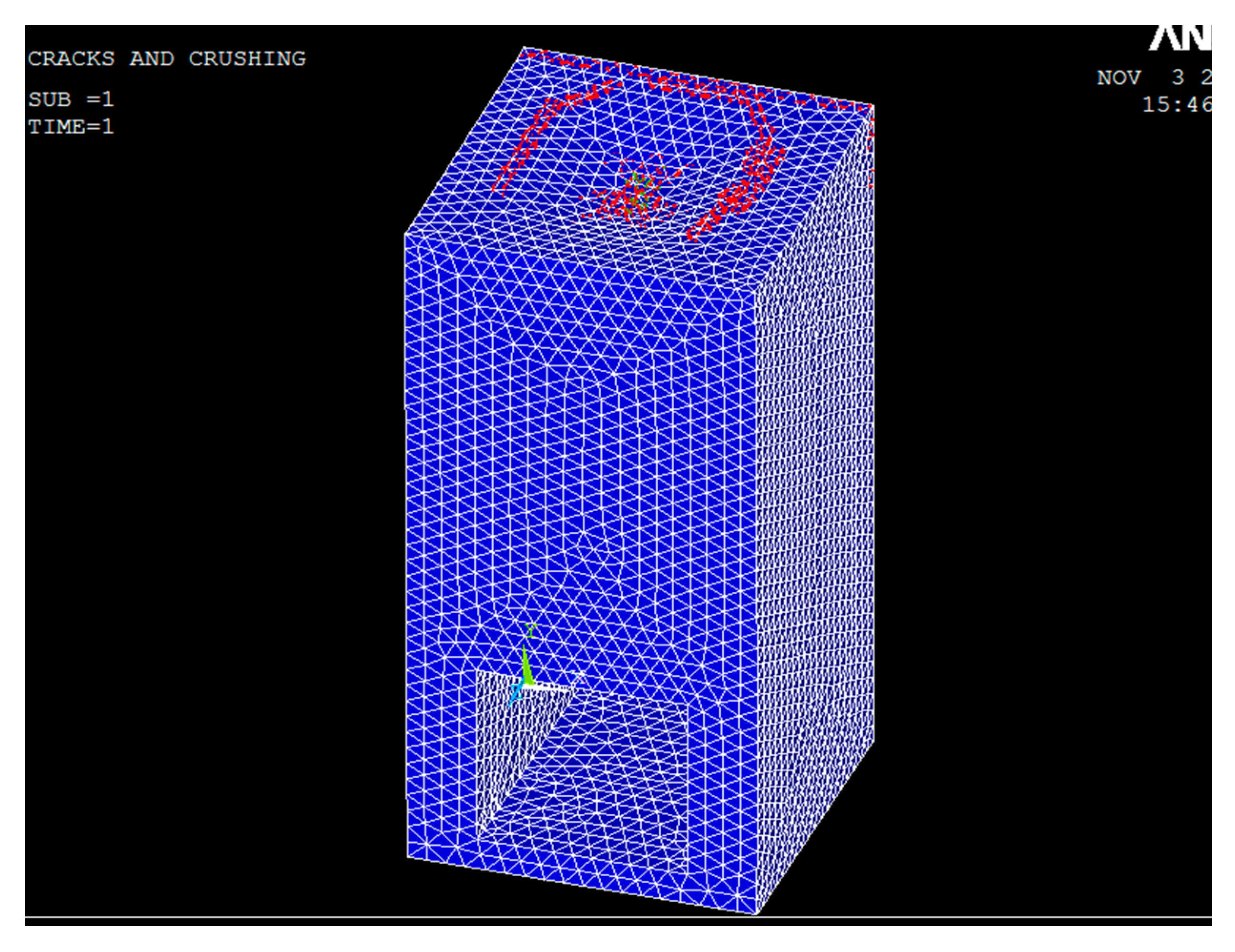
3.2.2. Transverse Deformation for the Top Ceiling-Slab

Shown in Figure 10 is the deformation distribution in the y-direction for the OWC air-chamber. It shows that the largest deformation in the y-direction for the chamber may occur at the lower parts of the chamber structure along the vertical side walls. Since the deformation was 0.102 × 10—5 m in-plane of the sidewall, and therefore, relative to the height of the sidewall, 11.0 m, the corresponding strain was 0.93 × 10—7, a value much smaller than 0.003. However, y-direction was in the out-of-plane direction of the ceiling panel and the downward deformation was 0.013488 m. Relative to the thickness of the ceiling slab, 0.5 m, the corresponding strain in the out-of-plane direction was 0.026976, which is a value well over the allowed capacity for the concrete strain.

3.2.3. Transverse Deformation for the Side-Wall

Presented in Figure 11 is the deformation distribution in the x-direction for the OWC air-chamber. Both the maximum (positive) and the minimum (negative) exist simultaneously on the ceiling-panel. The values are similar, namely, 0.00168 m, and relative to the dimension of x-direction, the strain was 0.000336, which is much smaller than the strain capacity of concrete material. For the sidewall of the chamber deformations in the x-direction is the out-of-plane motion and critical to the structural safety. As obtained from the analysis, the largest deformation was about 0.0011 m, which based on the thickness of the sidewall, 1.0 m, the corresponding strain was 0.0011, smaller than the maximum strain of the concrete.

3.2.4. Discussions on the Deformation of Chamber Members

From the analysis presented above, we found that in terms of the structural safety, the air-chamber of an OWC conversion system attached to a caisson breakwater structure cannot satisfy the general requirement of structural safety. Both the top ceiling slab and the front curtain wall were not strong enough to sustain a design storm of 50-year return period. Therefore, some questions arise: (1) If a design-wave based on a storm with 50-year period is suitable for the design of an OWC converter based on a caisson breakwater structure? (2) If the structure can be modified to sustain the design wave based on 50-year return period? (3) Is there any other choices to improve the structural safety of the very design?
Traditionally, structures located on the coast or in the water have very large volume and mass and therefore, a rigid-body theorem is applied for the design, which means that there is no deformation in the material or the structural members. Without considering the deformation or the material properties for the structure, many kinds of design for an OWC converting system can be proposed and analyzed for their function and converting efficiency based on fluid mechanics. However, when we carefully examine the structural safety by taking account all of the factors related to the properties of material, structural dimension, and environmental conditions of the location, the analytical results remind us that structural safety is still essential.
Going back to the questions that arose after the analysis for the structural safety, a storm of 50-year return period would probably be too much for an associated structure attached to the main structure-the caisson breakwater. So long as the damage of the associated structure would not affect structural safety and operation of the main structure, a design-wave based on a storm of shorter return period can be considered. To maintain the structural safety of the chamber of the OWC system, a compromise between the converting efficiency and the structural safety probably needs to be taken into account because a larger air-chamber will take more wave forces and the associated structural members also need to be designed with stronger material. As was found in the results of structural safety analysis, the weak parts of an OWC air-chamber are the curtain wall in the gate of incident wave and the top ceiling-slab. This phenomenon was also observed during a big-storm that hit the on-field application, as in the case of the Matriku OWC Power Plant [12].
Presented in Figure 12 is the potential cracking line for the air-chamber of the OWC converter attached to the caisson breakwater. Most cracks occurred on the top ceiling of the chamber as was indicated in the analysis; the ceiling slab would suffer the most serious deformations and according to the analysis the strain in the transverse direction was well over the allowed capacity for the concrete material. This phenomenon needs to be carefully watched because when the chamber of the OWC converter is under operation, the air-pressure induced from heaving waves may further worsen the problem. Even though the cracks will occur when an extreme environmental condition such as the designed storm of 50-year return period is applied, the regular operation may also cause a fatigue damage to the ceiling slab and the curtain wall. Especially when the air in the chamber is not allowed to flow out as the case studied, the induced pressure from elevated water in the chamber could further press the walls and ceiling-slab inside the chamber and cause severe deformation and then damages for the structural members.

4. Evaluation of Air-pressure in the Chamber during the Operation of Wave Energy Conversion

For the safety analysis of the chamber during the operation of the OWC system installed in the caisson structure, the theorem of unsteady Navier–Stokes equations in conservation form including continuity equations, equation of momentums, and equation of turbulence dynamics were applied as presented in the previous section. This theorem combined with numerical tool of CFX in ANSYS was also applied to the study. Before the application of the analytical method to the study, a verification was performed by reproducing and comparing the results obtained from the on-field study of Goda’s experiment [1] in Sakeda, Japan. That study is currently the sole one that may provide a full-scale on-field experimental data for a full-scale wave energy converter of which the variation of both the air pressure and water elevation in the air-chamber were shown.

4.1. Theorem of Fluid Mechanics Applied in the Study

In this study, a theorem of unsteady Navier–Stokes equations in conservation form, consisting of continuity equations, equation of momentums, and equation of turbulence dynamics, are applied and shown as follows [21,22].
Continuity equation:
ρ t + · ( ρ U ) = 0
Equation of momentum:
ρ U t + · ( ρ U × U ) · ( μ e f f U ) = · p + · ( μ e f f U ) T + B
where B is the sum of body force, μeff is the effective viscosity, and p’ is the revised pressure. The effective viscosity and the revised pressure can be presented as
μ e f f = μ t + μ
p = p + 2 3 ρ k
It is also noticed that μt is the viscosity of the turbulence, which according to the assumption of k-ε model, is related to the dynamic energy and the dissipation of the dynamic energy as presented as
μ t = C μ ρ k 2 ε
where k is obtained directly from the equation of dynamic energy and equation of energy dissipation. The equation of turbulence dynamic energy and equation of energy dissipation are presented as follows
( ρ k ) t + · ( ρ U k ) = · [ ( μ + μ t σ k ) k ] + P k ρ ε
( ρ ε ) t + · ( ρ U ε ) = · [ ( μ + μ t σ ε ) ε ] + ε k ( C ε 1 P k C ε 2 ρ ε )
where C ε 1 , C ε 2 , σ k , and σ ε are constant parameters to be determined empirically, while P k is related to viscosity and floating force and can be presented as
P k = μ t U · ( U + U T ) 2 3 · U ( 3 μ t · U + ρ k ) + P k b

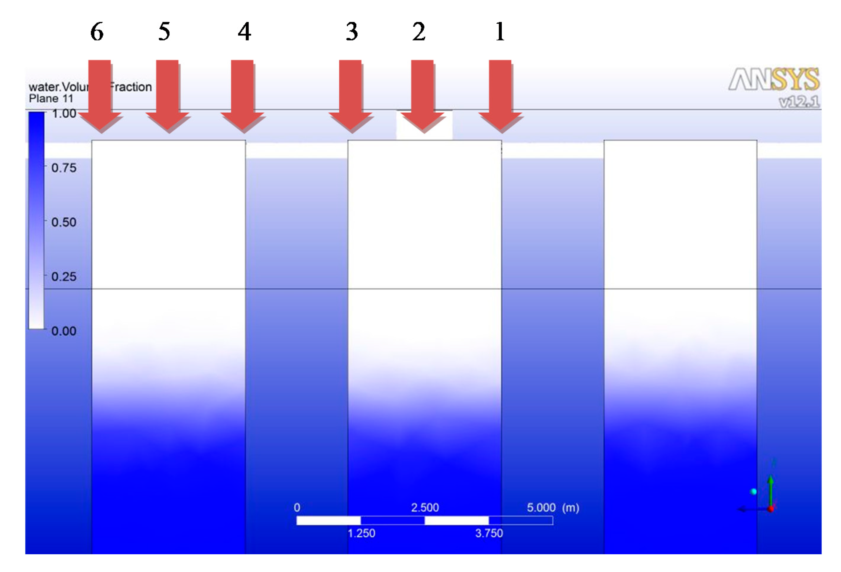
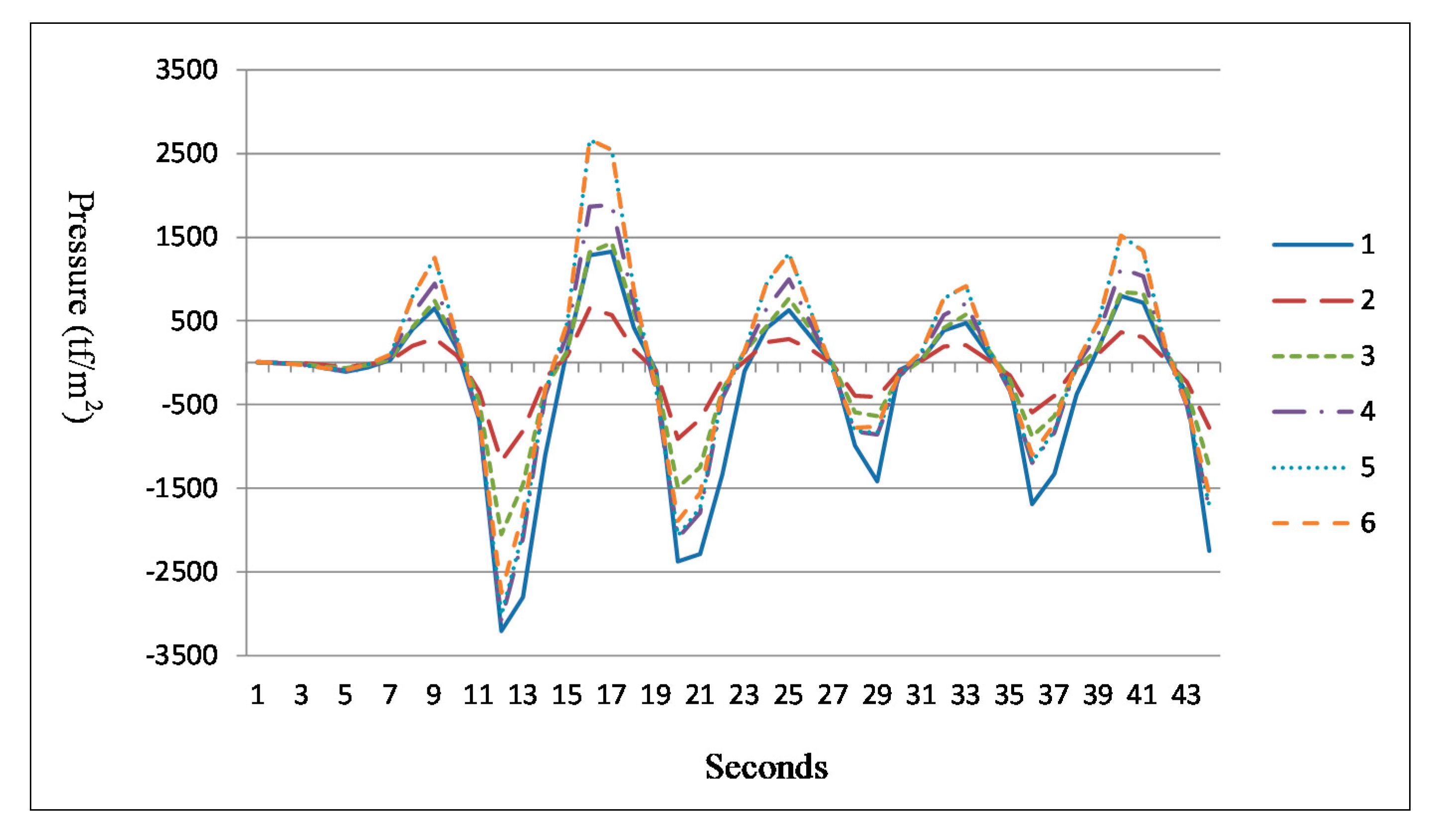
4.2. Analysis of Wave-Induced Air Pressure in the Chamber

The verification of the numerical method applied in this study was carried out by comparing the analytical results with the on-field experimental results when the conditions were set as similar as possible [18,19]. For Goda’s on-field study, a 20 minute data collection was made at Sakeda Harbor, where during the testing day, the wave-height was 2.2 m to 3.0 m (irregular waves on site). In this study a regular wave with wave-height of 2.5 m (regular wave analysis) was set and a one minute analysis was performed for the comparison of which two sections of experimental data within a 20 min were selected. It was found that even though the analytical results were slightly larger than the on-field data [23], considering the uncertainties of the on-field test such as the wave-height, which was irregular, and the data captured for the comparison, which were only small parts, the result was still encouraging.
An OWC wave converting system was proposed based on the available features for the harbor such as the depth of water in front of the breakwater, angle between wave direction and the normal direction of the caisson breakwater, and structure size of the caisson breakwater. A case is simulated for a breakwater of caisson type located in the Kaohsiung Port in Taiwan facing north-west where the water depth h = 9.5 m. According to a 10-year return period for the summer season (storm season) of local climate records, a design wave was used in simulation as: wave–height H = 1.0 m and wave-period T = 7 s. It was noticed that the wave condition applied for the case study was much smaller than the wave condition for the analysis of structural safety. This was because the design criteria applied for an offshore structure was much stricter, as a 50-year or larger return period was required, while for the case study a 10-year return period was considered suitable for regular daily performance.
Based on the shape and dimensions of the caisson structure to be modified with an OWC conversion system, a set of OWC system was designed and installed in the caisson breakwater. As shown in Figure 1, the OWC was installed at the front side of the caisson breakwater facing the incident waves so that it could capture the maximum wave energy to convert it into electricity power. It is a similar type to Goda’s test but the dimension was modified based on the conditions of the location port.
The typical response of air pressure near the ceiling-slab of the chamber at various positions, namely, from 1 to 6 as referred to Figure 13 and shown in Figure 14, where it is noticed that the air chambers are connected to each other with channels while only one orifice is allowed for every set of three-chambers. It can be observed that the position with lowest positive pressure is located right at the orifice when the air pressure at the other position increases corresponding to the distance away from the orifice. The position with highest negative pressure is at position 1 just next to the orifice. According to results of the structural safety analysis for the chamber members, the ceiling-slab will suffer the largest deformation and the pressure in the chamber will also increase the deformation if the exerting pressure is in the same phase to the out-of-plane dynamic motions of the structural deformation.
It was found that through the fluid mechanic analysis the greatest pressure exerting on position 1 of the chamber was 3210 tf/m2 or 31.46 MPa downward (negatively) during the operation of the OWC system. It is small and about 1/10 of the designed allowed pressure that may exert on the ceiling slab. The largest pressure occurred at the corner of the ceiling-slab, where the separation-wall could also provide the tension resistance to the slab. However, even without a wall to brace the ceiling-slab, it could still hold the pressure occurs during a regular operation of OWC system subjected to a wave of 10-year return period. The concern will be more on the issue of fatigue, which was not analyzed in this study since the direction of the pressure on the ceiling slab was applied alternatively and continuously.

5. Conclusions

In this study, an OWC wave power converting system based on a caisson breakwater was proposed and analyzed for both the structural safety and the performance in the power converting efficiency. For the structural safety analysis, two parts of analysis were carried out, namely, the first part for the overall structural safety and the second part particularly for the structure of air chamber of the OWC converter. The analysis on the chamber included both the elastic structural analysis and the air pressure in the chamber built in the caisson breakwater.
(1)
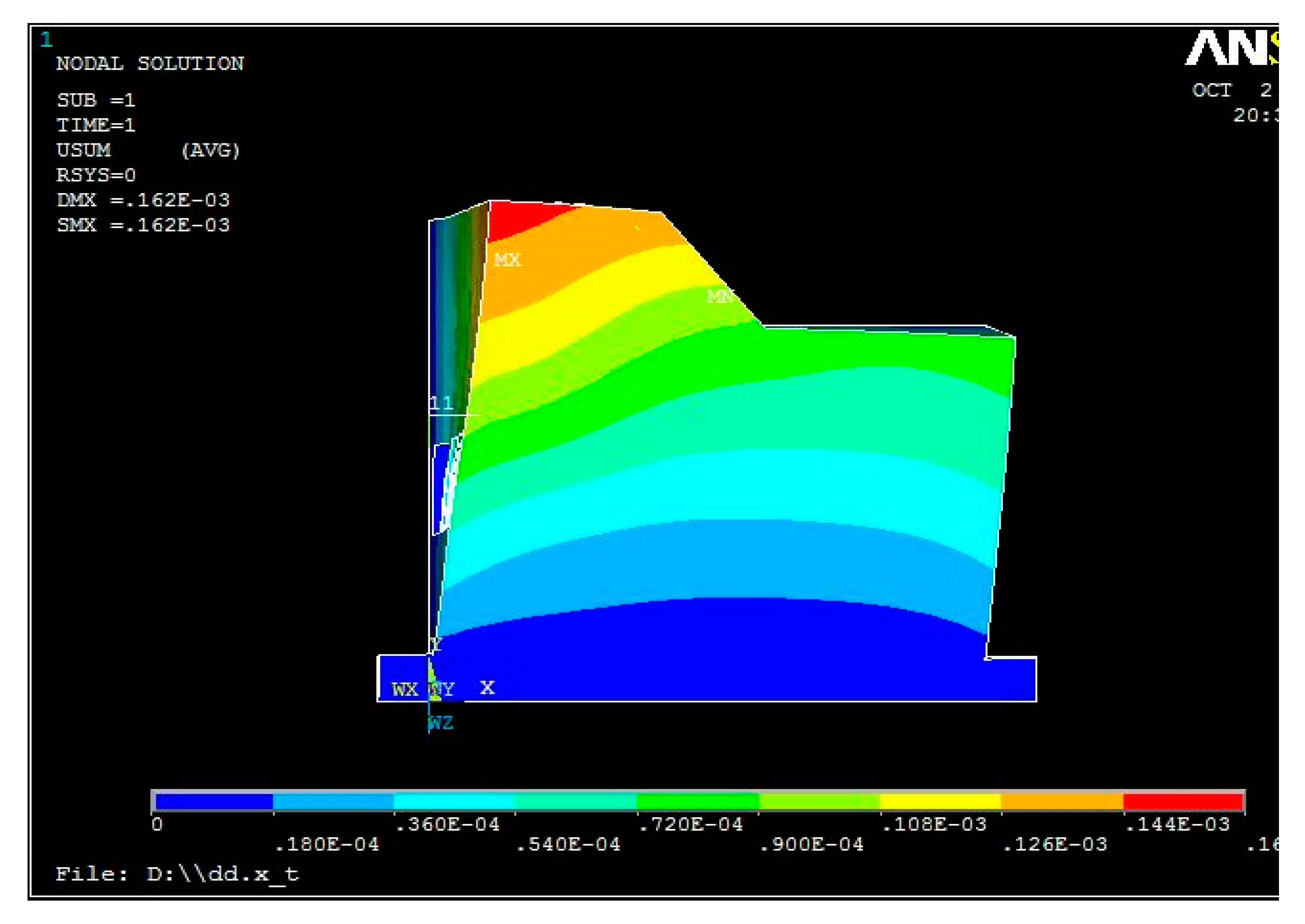
According to the analysis for the structural safety of this study, for the whole structural safety that included both the caisson breakwater and attached OWC system, the deformations induced from the design-wave, which was based on a storm-wave of 50-year return period, was under the capacity of the concrete material.
(2)
The second part analysis of the structural safety, particularly focused on the air-chamber of the OWC converter, where the maximum deformation occurred transversely at the ceiling-slab of the air-chamber for the OWC converter, whereas the front curtain wall subjected to wave-impact directly would also deform greatly, but not so significantly. The developed strains for both the ceiling-slab and the front curtain-wall were well over the strain limit for a concrete material and therefore, when the chamber structure was subjected to a wave close to the designed storm-wave as utilized in the analysis, a major damage may occur on both the ceiling-slab and the front curtain-wall.
(3)
According to the study of the air-pressure induced by the heave motion of the waves in the chamber, the pressure was small and would not significantly influence the structural safety of the OWC chamber attached to a caisson structure.
(4)
It is concluded that when the OWC is attached to a traditional breakwater structure, the location will be an important factor to decide the performance of energy converting efficiency. To design an OWC structure that may sustain a storm wave of 50-year return period could be expensive. In terms of economic consideration, as long as the damage of the associated structure would not affect the structural safety and operation of the main structure, a design-wave based on a storm of shorter return period should be considered.

Author Contributions

Conceptualization, H.H.L.; Methodology, H.H.L.; Software, C.-Y.L. and T.-Y.W.; validation, H.H.L.; Writing—original draft preparation, H.H.L.; Writing—review and editing, H.H.L.; Supervision, H.H.L. and Y.-F.C.; Project administration, H.H.L. and Y.-F.C.; Funding acquisition, H.H.L. and Y.-F.C.; All authors have read and agreed to the published version of the manuscript.

Acknowledgments

This research was financially supported in part by the Ministry of Transportation and Communication (MOTC), Taiwan, under grants “MOTC IOT-103-H2DB005c”. It is gratefully appreciated.

Conflicts of Interest

The authors declare no conflict of interest.

References

  1. Goda, Y.; Nakada, H.; Ohneda, H.; Suzuki, M.; Takahashi, S.; Shikamori, M. Results of field experiment of a wave power extracting caisson breakwater. Proceedings Ocean. Dev. 1991, 7, 143–148. [Google Scholar] [CrossRef] [Green Version]
  2. Goda, Y.; Shinda, T.; Chiyama, S.; Ohneda, H.; Suzuki, M.; Takahashi, S.; Shikamori, M.; Takaki, Y. Experiment of a wave power extracting caisson breakwater. Proceedings Ocean. Dev. 1989, 5, 1–6. [Google Scholar]
  3. Spanos, P.D.; Strati, F.M.; Malara, G.; Arena, F. An approach for non-linear stochastic analysis of U-shaped OWC wave energy converters. Probabilistic Eng. Mech. 2018, 54, 44–52. [Google Scholar] [CrossRef]
  4. Boccotti, P. Comparison between a U-OWC and a conventional OWC. Ocean. Eng. 2005, 34, 799–805. [Google Scholar] [CrossRef]
  5. Sheng, W. Power performance of BBDB OWC wave energy converter. Renew. Energy 2019, 132, 709–722. [Google Scholar] [CrossRef]
  6. Ansarifard, N.; Fleming, A.; Henderson, A.; Kianejad, S.S.; Orphin, J. Comparison of inflow and outflow radial air turbines in vented and bidirectional OWC wave energy converters. Energy 2019, 1821, 159–176. [Google Scholar] [CrossRef]
  7. Elhanafi, A.; Kim, C.J. Experimental and numerical investigation on wave height and power take–off damping effects on the hydrodynamic performance of an offshore–stationary OWC wave energy converter. Renew. Energy 2018, 125, 518–528. [Google Scholar] [CrossRef]
  8. Simonetti, I.; Cappietti, L.; Elsafti, H.; Oumeraci, H. Evaluation of air compressibility effects on the performance of fixed OWC wave energy converters using CFD modelling. Renew. Energy 2018, 119, 741–753. [Google Scholar] [CrossRef]
  9. Pawitan, K.A.; Dimakopoulos, A.S.; Vicinanza, D.; Allsop, W.; Bruce, T. A loading model for an OWC caisson based upon large-scale measurements. Coast. Eng. 2019, 145, 1–20. [Google Scholar] [CrossRef] [Green Version]
  10. Viviano, A.; Musumeci, R.E.; Vicinanza, D.; Foti, E. Pressures induced by regular waves on a large scale OWC. Coast. Eng. 2019, 152, 103528. [Google Scholar] [CrossRef]
  11. Garrido, A.J.; Otaola, E.; Garrido, I.; Lekube, J.; Maseda, F.J.; Liria, P.; Mader, J. Mathematical modeling of fluid and structure interaction in ocean engineering. Ocean. Eng. 2015, 2015, 727982. [Google Scholar] [CrossRef] [Green Version]
  12. Medina-Lopez, E.; Allsop, W.; Dimakopoulos, A.; Bruce, T. Conjectures on the failure of the OWC breakwater at Mutriku. In Proceedings of the Conference Coastal Structures, Boston, MA, USA, 9–11 September 2015. [Google Scholar]
  13. Benrugeig, P.; Murphy, J. Modelling air compressibility in OWC devices with deformable air chambers. J. Mar. Sci. Eng. 2019, 7, 268. [Google Scholar] [CrossRef] [Green Version]
  14. Kim, J.-S.; Nam, B.W.; Kim, K.-H.; Park, S.; Shin, S.H.; Hong, K. A numerical study on hydrodynamic performance of an inclined OWC wave energy converter with nonlinear turbine–chamber interaction based on 3D potential flow. J. Mar. Sci. Eng. 2020, 8, 176. [Google Scholar] [CrossRef] [Green Version]
  15. Huang, Z.; Xu, C.; Huang, S. A CFD simulation of wave loads on a pile-type oscillating-water-column device. J. Hydrodyn. 2019, 31, 41–49. [Google Scholar] [CrossRef]
  16. Ambühl, S.; Sørensen, J.D. Sensitivity of risk-based maintenance planning of offshore wind turbine farms. Energies 2017, 10, 505. [Google Scholar] [CrossRef] [Green Version]
  17. Lee, H.H.; Chen, C.-H. Parametric study for an oscillating water column wave energy conversion system installed on a breakwater. Energies 2020, 13, 1926. [Google Scholar] [CrossRef] [Green Version]
  18. Lee, H.H.; Chiu, Y.-F.; Lin, C.-Y.; Chen, C.-H.; Huang, M.-H. 2016, Parametric study on a caisson based OWC wave energy converting system. World J. Eng. Technol. 2016, 4, 3D. [Google Scholar]
  19. Goda, Y. Random Seas and Design of Maritime Structures; Tokyo University Press: Tokyo, Japan, 1985. [Google Scholar]
  20. ACI 357.3R-14. Guide for Design and Construction of Waterfront and Coastal Concrete Marine Structures. ACI Committee 357. 2014. Available online: https://www.concrete.org/Portals/0/Files/PDF/Previews/357_3R_14preview.pdf (accessed on 2 July 2014).
  21. Sarpkaya, T.; Isaacson, M. Mechanics of Wave forces on Offshore Structures; Van Nostrand Reinhold Company: New York, NY, USA, 1981. [Google Scholar]
  22. Milne-Thomson, L.M. Theoretical Hydrodynamics; The MacMillan Co.: Toronto, ON, Canada; Macmillan: New York, NY, USA, 1960. [Google Scholar]
  23. Chiu, Y.-F.; Lee, H.H.; Lin, C.-Y.; Chang, F.-T. Study on a Caisson Based OWC Wave Energy Converting System. 2014. Available online: http://www.hcirp.jornal.wjet (accessed on 27 July 2015).
Figure 1. Schematic drawing of a caisson structure with oscillating water column (OWC) converter.
Jmse 08 00506 g001
Figure 2. Side view of a caisson structure with OWC converter (redrawn after Chiu et al. [20]).
Jmse 08 00506 g002
Figure 3. Schematic drawing of environmental loading on caisson structure.
Jmse 08 00506 g003
Figure 4. The distribution of the environmental loadings.
Jmse 08 00506 g004
Figure 5. Deformation of caisson breakwater along the wave direction.
Jmse 08 00506 g005
Figure 6. Dimensions of the structural members of OWC chamber in the caisson breakwater.
Jmse 08 00506 g006
Figure 7. The grid meshes of the element for the chamber.
Jmse 08 00506 g007
Figure 8. The arrangement of steel reinforcement in the chamber.
Jmse 08 00506 g008
Figure 9. Deformation variation for the chamber structure in z-direction.
Jmse 08 00506 g009
Figure 10. Deformation variation for the chamber structure in y-direction.
Jmse 08 00506 g010
Figure 11. Deformation variation for the chamber structure in x-direction.
Jmse 08 00506 g011
Figure 12. Potential cracking line for the chamber structure.
Jmse 08 00506 g012
Figure 13. Schematic view of inner part of the air-chamber.
Jmse 08 00506 g013
Figure 14. The air-pressure in the various location of chamber.
Jmse 08 00506 g014

