Article

A Novel Double Layered Hybrid Multi-Robot Framework for Guidance and Navigation of Unmanned Surface Vehicles in a Practical Maritime Environment †

1
Intelligent Mobile Platform (IMP) Research Group, KU Leuven, 3000 Leuven, Belgium
2
Istituto di iNgegneria del Mare (INM), Consiglio Nazionale delle Ricerche (CNR), 16149 Genova, Italy
3
Autonomous Marine Systems (AMS) Research Group, University of Plymouth, PL4 8AA Plymouth, UK
*
Authors to whom correspondence should be addressed.
This paper is an extended version of our paper published in 11th IFAC Conference on Control Applications in Marine Systems, Robotics, and Vehicles (CAMS 2018) titled “A Two Layered Optimal Approach towards Cooperative Motion Planning of Unmanned Surface Vehicles in a Constrained Maritime Environment”; DOI: https://doi.org/10.1016/j.ifacol.2018.09.458.
J. Mar. Sci. Eng. 2020, 8(9), 624; https://doi.org/10.3390/jmse8090624
Submission received: 30 July 2020 / Revised: 10 August 2020 / Accepted: 13 August 2020 / Published: 19 August 2020
(This article belongs to the Special Issue Unmanned Marine Vehicles)

Abstract

:
Formation control and cooperative motion planning are two major research areas currently being used in multi robot motion planning and coordination. The current study proposes a hybrid framework for guidance and navigation of swarm of unmanned surface vehicles (USVs) by combining the key characteristics of formation control and cooperative motion planning. In this framework, two layers of offline planning and online planning are integrated and applied on a practical marine environment. In offline planning, an optimal path is generated from a constrained A* path planning approach, which is later smoothed using a spline. This optimal trajectory is fed as an input for the online planning where virtual target (VT) based multi-agent guidance framework is used to navigate the swarm of USVs. This VT approach combined with a potential theory based swarm aggregation technique provides a robust methodology of global and local collision avoidance based on known positions of the USVs. The combined approach is evaluated with the different number of USVs to understand the effectiveness of the approach from the perspective of practicality, safety and robustness.

1. Introduction

Motivated by the increased presence of autonomous agents, research organisations and industrial firms are putting their effort in the development of unmanned vehicles, able to operate autonomously in the marine environment. Current state of high-performance marine vehicles operating in marine environment were once just a figment of our imagination as a prototype tool. They are consolidated reality of today’s maritime framework, employed in the most diverse array of applications ranging from reconnaissance in hostile areas to operations in dangerous weather conditions to name a few.
Substantial research has been conducted in the last two decades towards increasing autonomy of unmanned surface vehicles (USVs), being the basis of the near-future autonomous ships. Moreover, a step further in the development of autonomous systems is the capability of operating in a team, so as to improve the overall system performance in terms of cost and safety. With this final objective of allowing a multi-USV agent team to navigate autonomously within a commercial route such as coastal area or an harbour, a number of problems have to be solved in order to provide the essential capabilities to the system to operate in an autonomous and safe manner. Formation control and cooperative motion planning are two major areas being investigated in the literature towards the study of the multi vehicle systems. A list of key factors that needs to be considered for designing algorithms related to formation control and cooperative motion planning are already listed in the Figure 1 with formation control being the most widely investigated area. It is quite evident from the Figure 1 that both research areas share a large number of key factors and there is a strong need to develop a hybrid approach combining the key features from both areas. However, it is most important to discuss details of different approaches associated with formation control and cooperative motion planning before delving into the details of the multi USV framework adopted in the current study.
The organisation of the current study is as follows: In Section 2, an overview of the architecture of a multi vehicle system and a comprehensive comparison and analysis of the strategies associated with the multi vehicle system is provided. The adopted methodology, concepts of basic path-following with multi vehicle coordination are discussed in the Section 3 while in the Section 4, results of coordinated vehicles motion are presented. Lastly, conclusions and future work are reported in Section 5.
The current study extends the work of [2] through the incorporation of three major characteristics within the existing framework which are:
  • The practical maritime environment of Portsmouth harbour in the existing framework, where an open sea environment has been considered comprising of non-static obstacles.
  • The feature of external collision avoidance with shoreline by modelling shoreline as a set of repulsive points using a repulsive potential function.
  • An optimal and computationally efficient path within the existing framework for navigating the swarm of USVs.

2. Multi Vehicle System and Formation

The evolution of the concept of the cooperative behaviour of the multi vehicle system is inspired from the animal behaviour such as self organisation of ants or swarming of bees, where the formations help in the survival and evolution of the species ([3,4]). The initial effort in understanding the cooperative behaviour of multi vehicle systems inspired from the animal behaviour started in the 1980s leading to development of ACTor-based robots and equipment synthetic system (ACTRESS), a multi robot system architecture developed in Japan ([5]).
The initial real world application of the multi vehicle system started with the use of UGVs in disaster management followed by the deployment of their applications in area mapping and surveillance ([6,7]). Later this advancement in the technology was extended in space research for the purpose of planetary exploration ([8]). With respect to multi UAV systems, a huge amount of research has happened over last two decades for a variety of applications including disaster management and environmental monitoring ([9,10]) and is still an open research area.
In the research area of the marine robots where a good number of studies conducted during the last decade have happened in the area of multi AUV system towards applications such as bathymetric surveys, ocean monitoring and data acquisition ([11,12]). In terms of a multi USV framework where the current thesis focuses on, fewer studies have taken place in the last decade with a focus on applications such as collaborative anti-submarine warfare, surveillance of territorial waters and underway ship replenishment ([13,14]). It is worth noting from the literature that compared to the research on developing approaches for fleet of UGVs, UAVs and AUVs very fewer studies have taken place in the area of USV formations and there is a strong need to explore the area of cooperative behaviour with a multi USV framework. In fact, owing to the nature of the USV operations, an USV plays an important role in the large scale cross platform cooperation among different unmanned vehicles in the maritime environment as shown in Figure 2. This significance is quite evident from the recent defence reports published by UK and US Department of Defence (DoD) ([15,16]).

2.1. Multi Vehicle System Architecture

A generic architecture towards cooperative behaviour of a multi vehicle formation is shown in Figure 3 which comprises of three layers namely, task management, path planning and task execution [17]. The task management layer takes care of the formation shape and formation allocation of the multi vehicle system based on the requirements of the mission i.e., improving the efficiency of the mission in terms of the spatial and temporal coverage. Towards the literature pertaining to the marine robots, the concept of self organising map (SOM) has been extensively used in the task management of the multi vehicle systems. [18] has used SOM towards dynamic task assignment and path planning of a multi AUV system in a three dimensional underwater environment along with the work of [19] which used the approach of SOM to assign a team of AUVs to achieve multiple target locations in a dynamic ocean environment. With respect to USVs, the work of [20] has used SOM approach integrated with Fast Marching (FM) based reactive method towards collision avoidance.
Figure 2. Schematic of the UAV and unmanned surface vehicle (USV) formation (Source: [21]).
Jmse 08 00624 g002
Path planning layer is the second layer of the multi vehicle architecture which comprises of three components of environmental mapping, cooperative path planning and real time trajectory modification. A detailed survey towards path planning of single and multiple USVs has been reported in the [22]. However, a number of recent studies needs a special mention in order to deal with real time trajectory modification and emergency situations. The work of [23,24,25,26,27] have made an effort recently to integrate the task planning with dynamic constraints and a practical maritime environment to generate trajectories with practical applications.
Task execution takes generated paths as an input from the path planning module where dynamic variables of the vehicle i.e., velocity, position etc., are used in closed loop control systems to modify the trajectories of the fleet of vehicles in real time. Extensive details of the review papers associated with such marine control systems have already been mentioned in the [28].

2.2. Approaches Associated with Cooperative Behaviour of Multi Vehicle Systems

Two research approaches of formation control and cooperative path planning have been investigated to understand the cooperative behaviour of the multi vehicle system in the literature. A huge amount of research has been conducted in the area of autonomous vehicles over the last four decades in the area of formation control which can be found in the different review studies of [29,30,31]. The key factors associated with the formation control and cooperative path planning are listed in Figure 1. Projects within the European Union and United States are major examples of the development of multi vehicle framework for marine robots. It started with the CADRE system ([32]) project, where a network of AUVs and USVs were used to cooperate autonomously to conduct mine countermeasure using high accuracy navigation and a multi modal architecture. The same framework was extended in the Autonomous Ocean Sampling Network II (AOSN II) project ([33]), where there is complete interconnection and cooperation of aerial, surface and underwater (including gliders) vehicles, with the aim of developing a heterogeneous and “intelligent” monitoring network. Another major milestone was the GREX project ([34]), towards creation of a conceptual framework for heterogeneous swarm of robots working in cooperation to achieve mission goals optimally. Another important work in direction of creating a reliable acoustic underwater network as basis for communication and navigation was conducted through MORPH project [35]. The following section will make a discussion on the various formation control strategies, their comparison and their implementation in the area of marine robotics.

2.3. Formation Control Strategies

The basic classification of the approaches associated with the formation control are shown in Figure 4. Three important features of formation control i.e., shape forming, shape maintenance and shape variation are being compared for their compatibility with each method of the formation control while the criteria of stability and real time for each method is being scored with high and medium as shown in Figure 4. Each of these approaches has its own advantages and disadvantages and their implementation on marine robots is explained in the following subsections.

2.3.1. Behaviour Based Approach

This approach is designed on the basis of the motion primitives associated with each robot such as obstacle avoidance, goal seeking and formation keeping where weighted sum of each of these primitives and interaction between robots is used to create motion patterns for multi vehicle systems. Sensor data are taken as input behaviour and output is sent to robots behaviours which can be viewed together as a structured network of interacting behaviours. A module coordinator finally decides a set of behaviours used to control the robot. This approach was initially proposed in the area of mobile robotics by [36] where a weighted sum of five behaviours namely, move to goal, obstacle avoidance, swirl, noise and formation keeping is used to control the formation of robots. With respect to USVs, the work of [37] used Null-Space-Based behavioural control (NSB) as guidance system aimed at guiding the fleet of surface vehicles in complex environment and simultaneously performing multiple tasks i.e., obstacle avoidance or formation keeping. The work of [38] addressed the concept of International Regulations for Collision Avoidance (COLREGs) compliance navigation of two USVs using the concept of behavioural control and optimality and validated simulations using first in-field demonstration. The studies of [39,40] have covered the area of application of behavioral approach in the area of AUVs.
The parallel and distributed communication among vehicles with less information being shared makes this approach advantageous for real time application although difficult mathematical formulation and unwarranted convergence are a few drawbacks associated with this approach.

2.3.2. Leader-Follower Approach

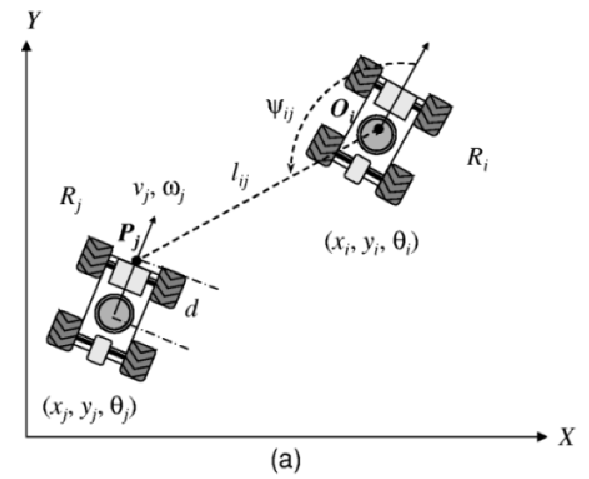
The leader follower approach works on the principle of few robots considered as leaders while the others act as followers where followers track the position and heading of the leader to some predefined temporal and spatial offset. A schematic of two robots using a basic leader follower controller is shown in the Figure 5.
Two popular feedback control methods as proposed by [41] are being used in this approach namely, l ϕ control and l l control. The l ϕ control method is used to maintain a desired relative distance l i j and a desired relative heading ψ i j between two robots as shown in Figure 5 while the l l method is used to maintain the desired relative distance between three robots i.e., l 23 and l 13 as shown in Figure 6.
This scheme has been much preferred in understanding the cooperative behaviour of marine vehicles due to its simplicity and scalability. During the last decade, a good number of studies like [42,43,44,45,46] has adopted a leader-follower framework in formation control of multiple USVs in which different techniques like non linear control, integrator backstepping, sliding mode control, Lyapunov backstepping and angular FM have been used respectively. Towards understanding the cooperative behaviour of AUVs, leader-follower approach has been used in the work of [47,48,49,50,51,52,53,54] through adoption of different control techniques for the formation control of multiple AUVs.
This approach is entirely determined by the trajectory of the leader which simplifies the problem of formation control to a tracking control. The followers follow the leader based on the WiFi communication between leader and followers. The WiFi communication is responsible for the sharing of velocity and position data between followers and leader based on which formation control approaches operate. However, a major drawback of this approach is that formation does not accept leader faults and in case of absence of a leader, a complete formation needs to be redefined.

2.3.3. Virtual Structure (VS) Approach

This approach considers the complete formation as a rigid body where the whole formation is considered as a VS. The dynamics of a single vehicle is translated into a desired motion of each robot in the VS and robot positions are updated according to the local or global path planner. The approach was initially proposed by [55] and a schematic of the approach is shown in Figure 7.
The approach comprises of four major steps as follows:
  • Define the dynamics of the VS and align the VS with the initial positions of the robot.
  • Define the heading of the VS.
  • Compute the individual trajectory for each robot from the start to the goal point as the corresponding robot contribute to an error of d i as shown in Figure 7.
  • Adjust the velocity of each robot to follow the desired trajectory closely, in addition to, maintaining the geometry of the VS.
A good number of studies has been conducted in the area of mobile and aerial robotics using a VS approach ([56,57,58]) while the work of [59] covers the area of formation control of underactuated ships using a VS approach. Despite its high fault tolerant capability, this approach suffers from lack of flexibility and high computational cost in a complex operational environment.

2.3.4. Artificial Potential Function

The concept was initially proposed by [60] and has been quite popular in the last decade in the formation control of multi robots systems and is quite evident from the work of [61,62,63,64]. In the area of marine robotics, some recent work in the application of artificial potential function towards formation control can be found in [65,66,67,68].
This approach can be applied in real time but suffers from the issues of local minima.

2.3.5. Graph Theory Based Approach

In this approach, kinematic or dynamic properties of the robots are expressed as nodes of a graph with edges representing constraints between the robots. Under this approach, control theory and dynamical systems theory is applied in combination with graph theory to study the formation controller and its stability. Many recent studies of [69,70,71] have used the communication network based control strategy, consensus based control strategy and stop-and-go strategy respectively to understand the formation control using graph theory. This method can represent any formation using graph although simulation hitherto remains a major drawback.

3. Methodology

The current study adopted a two layered approach towards the multi-USV framework problem. In the higher level of the hierarchy, a robust path planner based on a constrained A* approach was adopted to generate optimal waypoints, which were later smoothed using a polyfitting operation. This smoothed trajectory was given as an input to a lower level guidance system based on a virtual target (VT) approach integrated with a swarm aggregation algorithm based on an attraction- repulsion strategy. Figure 8 shows a schematic of the methodology adopted in the present study. The current study was simulated in a practical maritime environment of Portsmouth harbour using MATLAB. Portsmouth harbour was chosen here as the area of interest due to its significant commercial and industrial use in the UK maritime industry. All simulations were performed on a PC with Microsoft Windows 7 as OS with Intel i5 2.70 GHz quad core CPU and 16 GB RAM.
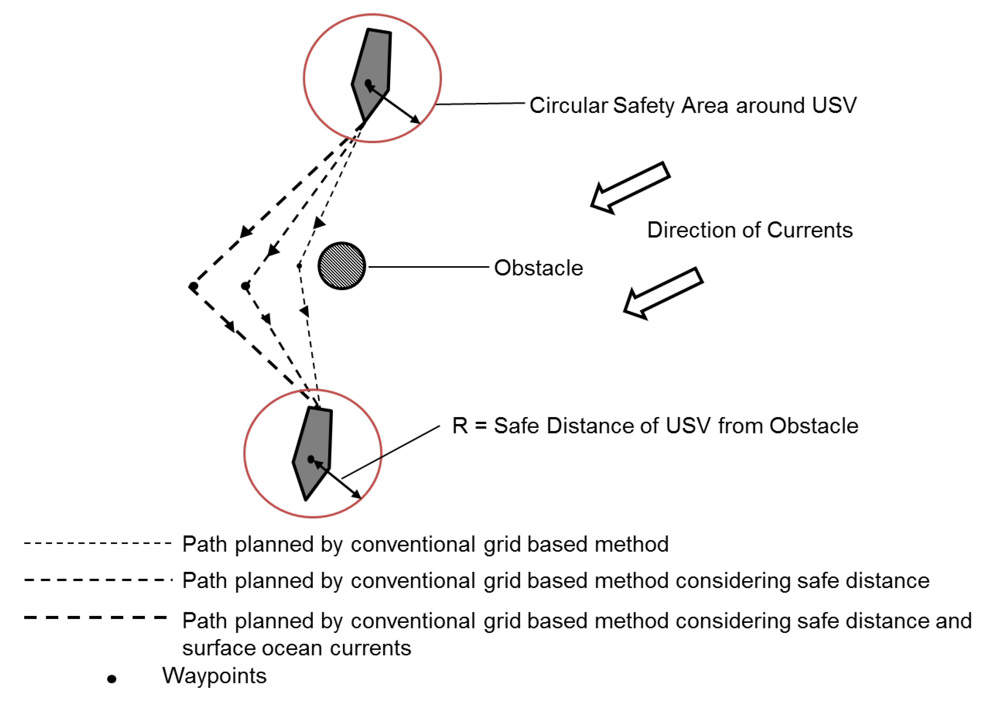
The current study adopted an A* approach with a USV enclosed by a circular boundary as a safety distance constraint on generation of optimal waypoints. The A* approach is a grid based path planning approach designed to find the shortest path in a cluttered environment by minimising the heuristic cost [72]. This resolved the problem of optimal path planning for an USV moving in a practical maritime environment, leading to generation of safer way-points with conservation of energy. Figure 9 describes a comparison of the path generated by conventional grid-based method against the path generated by conventional grid-based method considering safety distance and surface ocean currents.
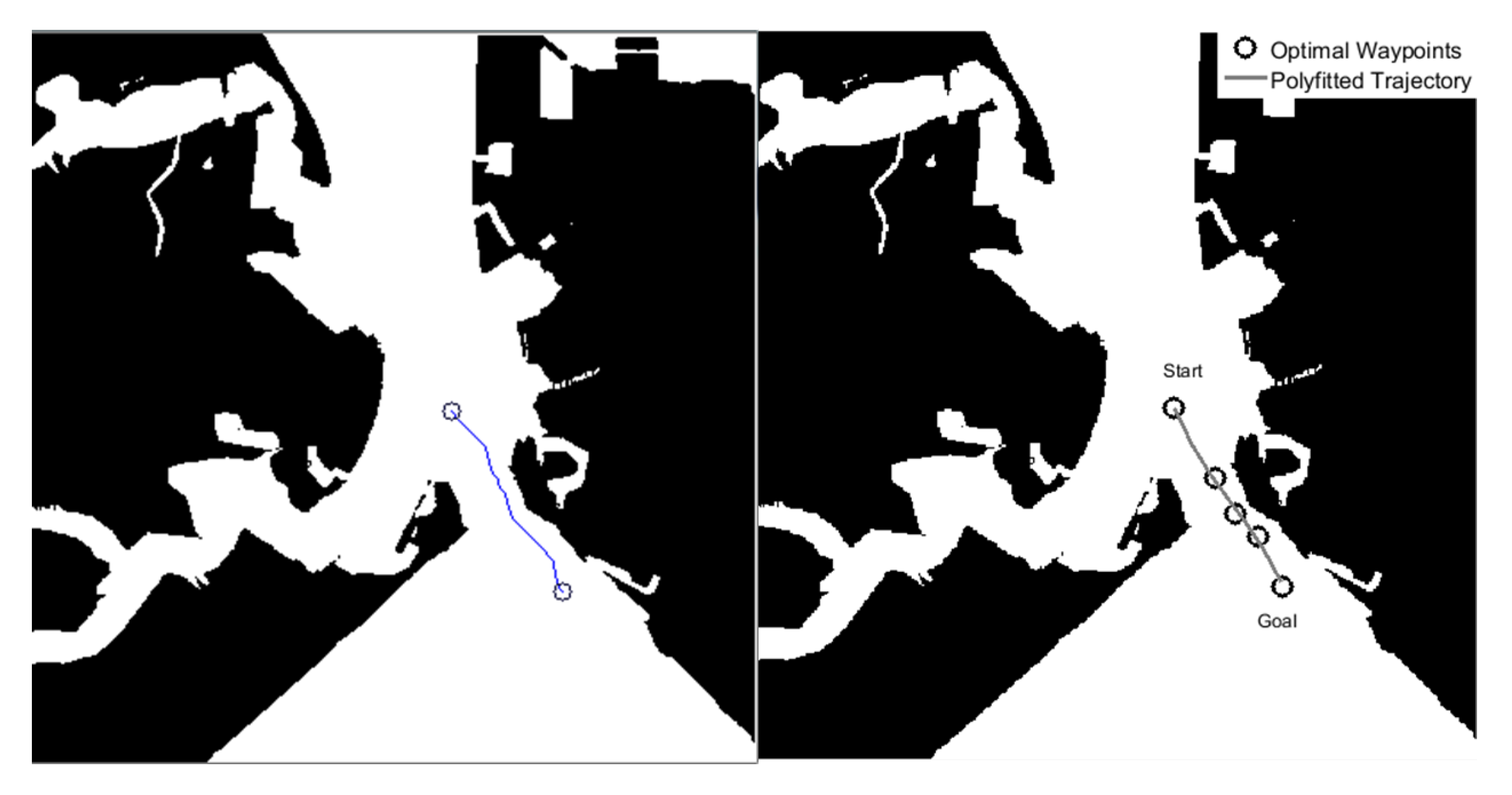
A constrained A* approach as described in the [72] with a safety distance of 20 pixels was chosen in the current study to generate optimal waypoints in a constrained channel of Portsmouth harbour. A zigzag trajectory was produced from the waypoints generated from the proposed approach. The chosen waypoints for smoothed trajectory are tabulated in Table 1. The waypoints were chosen so that complexity of the navigation in a constrained harbour was accounted for in an offline approach. The generated trajectory from the safety distance constrained A* approach and smoothed trajectory from chosen waypoints are shown in Figure 10.
The chosen waypoints were fitted to a polynomial parameterised in terms of γ γ ∈[0,61]. Parametric equations, P d ( γ ) used as an input towards online approach of path following and swarm aggregation are shown in Equation (1).
P d ( γ ) = x ( γ ) = γ + 238 , y ( γ ) = 0.000325 ( γ + 238 ) 3 + 0.2637 ( γ + 238 ) 2 . . 72.5508 ( γ + 238 ) + 6505

3.1. Preliminaries Related to Multi Vehicle Path Following

In this study, the swarm as defined by [73] was composed of a set X of n robots, each one characterised by the vector x i ( t ) R m with i = 1 , , n in Cartesian coordinates on a 2D plane. The instantaneous barycentre of the swarm was defined as x ˜ ( t ) = 1 / n i = 1 n x i i ( t ) and the vector distance of each robot from the centre is defined as ϵ i ( t ) = x i ( t ) x ˜ ( t ) . The collection of all robots and their distances from the barycentre was defined as X ( t ) = [ x 1 ( t ) . x n ( t ) ] and ϵ ( t ) = [ ϵ 1 ( t ) . ϵ n ( t ) ] .
The proximity graph G i = { V , E } , where V = { v i : i = 1 , , n } is the set of robots while the E = { ϵ i j } is the set of edges representing communication channel between the robots and the centre, defined the interaction among the robots. The communication channel existed if the agents i and j were within the visibility range R i j i.e., x i x j R i j with unidirectional communication from node i to node j. The Laplacian matrix associated with this graph G was defined as L ( G i ) = Δ ( G i ) A ( G i ) , where the A ( G i ) is the adjacency matrix of n × n elements whose generic element a i j = 1 if i j and ϵ i j E and a i j = 0 otherwise while Δ ( G i ) is the degree diagonal matrix of n × n elements whose elements are Δ i ( G i ) i.e., degree of the node i. This matrix was a weak diagonal symmetric matrix where the sum of rows and sum of columns were equal to zero.
The current study took into account the idea of guiding a complete swarm of USVs through an instantaneous barycentre of swarm acting as a VT that moves along the reference path where following assumptions are required:
  • Onboard Global Positioning System (GPS) is continuously measuring position of each USV in the swarm with reference to a common reference frame.
  • WiFi systems are providing a reliable data exchange needed to support inter-robot decentralised communication for position data sharing.
In order to achieve the above mentioned idea, a proper velocity is computed and imposed to the swarm aggregation algorithm, which in turn drive the motion of each USV in the USV swarm according to such reference velocity.

3.2. Path Following Algorithm

A graphical representation of the USV kinematics adopted in the current study for development of the path following algorithm is given in Figure 11. In general, two reference frames namely, Earth fixed reference frame < e > , where position and orientation [ x y z Ψ ] T of the USV is expressed and the body fixed reference frame < b > , where the relative surge and sway velocity [ u r v r ] T of the USV with respect to the water and yaw rate r are used to define the kinematics in the < e > frame as follows ([74]):
x ˙ = u r cos Ψ v r sin Ψ + x c ˙ y ˙ = u r sin Ψ + v r cos Ψ + y c ˙ Ψ ˙ = r
where [ x c ˙ y c ˙ ] denotes the sea current which is supposed to be irrotational and constant. Assuming that USV is moving with a constant surge with respect to the water with negligible sway, i.e., v r = 0 and u r ˙ = v r ˙ = 0 , the kinematic model represented in the Equation (2) can be rewritten as follows:
x ˙ = U cos Ψ e y ˙ = U sin Ψ e Ψ e ˙ = r u r 2 U 2 + u r U ( x c ˙ cos Ψ + y c ˙ sin Ψ ) = r η ( t )
where
U = x ˙ 2 + y ˙ 2 ; Ψ e = arctan y ˙ x ˙
denote the resultant velocity and orientation of the USV in < e > . The current work uses the concept of Serret–Frenet frame < f > which moves along the reference path followed by the VT vehicle and tracked by the real vehicle. With reference to Figure 11, a point P with position vector P = [ x p y p 0 ] T is defined in respect to < e > frame. The point B, attached to the USV is expressed as [ s 1 y 1 0 ] T in < f > frame. The rotational matrix to transform the parameters from < e > to < f > is defined in terms of Ψ f as follows:
R = cos Ψ f sin Ψ f 0 sin Ψ f cos Ψ f 0 0 0 1
Assuming r f = Ψ f and defining s as the signed curvilinear abscissa along the path, following expressions hold:
r f = Ψ f ˙ = c c ( s ) s ˙ ; c c ( s ) = g c ( s ) s ˙
where, c c ( s ) and g c ( s ) = d c c ( s ) / d s denote the path curvature and its derivative respectively. The velocity of P in the < f > frame is defined as:
d p d t f = s ˙ 0 0
The velocity of B in the < e > frame is defined as:
d x d t e = d p d t e + R 1 d d d t f + R 1 ( [ 0 0 r f ] T × d )
where, d is the position vector from P to B. The velocity of B in the < f > frame is obtained by multiplying the above equation with R and is as follows:
d x d t f = R d x d t e = d p d t f + d d d t f + [ 0 0 r f ] T × d
Based on the following relations
d x d t e = x ˙ y ˙ 0
d d d t f = s 1 ˙ y 1 ˙ 0
and
[ 0 0 r f ] T × d = 0 0 c c ( s ) s ˙ × s 1 ˙ y 1 ˙ 0 = c c ( s ) s ˙ y 1 c c ( s ) s ˙ s 1 0
Equation (5) can be rewritten as
R x ˙ y ˙ 0 = s ˙ [ 1 c c ( s ) y 1 ] + s 1 ˙ y 1 ˙ + c c ( s ) s ˙ s 1 0
Solving for s 1 ˙ and y 1 ˙ gives
s 1 ˙ = cos Ψ f sin Ψ f x ˙ y ˙ s ˙ ( 1 c c y 1 )
y 1 ˙ = sin Ψ f cos Ψ f x ˙ y ˙ c c s ˙ s 1
Replacing the top two equations in Equation (6) and introducing the variable β = Ψ e Ψ f , the final kinematic model in terms of the < f > frame, i.e., ( s 1 , y 1 ) coordinates are as follows:
s 1 ˙ = s ˙ ( 1 c c y 1 ) + U cos β y 1 ˙ = c c s ˙ s 1 + U sin β β ˙ = r e c c s ˙
where r e = Ψ e ˙ = r η ( t )
Following the geometrical and kinematical analysis carried above, the distance error model, expressed with respect to the frame < f > , has the following form ([74]):
ρ ˙ = c c ν 1 s ˙ + U cos β ν ˙ = c c s ˙ ρ + U sin β
In order to solve the path-following problem for a single-vehicle system, the aim was to develop a proper approach angle function Ψ * , designed to reduce the linear error components ( ρ and ν ) to zero. The desired angle Ψ * was a function of the cross-track error ν summed with the local path tangent, thus Ψ * = Ψ f + φ ( ν ) , where the function φ ( ν ) was required to satisfy the following constraints:
| φ ( ν ) | < π 2 ; ν φ ( ν ) 0 ; φ ( 0 ) = 0
Relying on a low level PI controller, providing an auto-heading regulator capable of tracking desired orientation profiles, it can be stated that considering the candidate Lyapunov function V ψ = 1 2 ( ψ ψ * ) 2 , the low level controller provided a behaviour such that V ˙ ψ 0 , i.e., the vehicle orientation converged to the desired angle ψ ψ * and it can be rewritten as β φ ( ν ) . Moreover it is worth noticing that when V ˙ ψ = 0 , an invariant set was defined, in which the condition β = φ ( ν ) holds. The task of the path-following controller design was achieved by the definition of the Lyapunov function V = 1 2 ( ρ 2 + ν 2 ) ; computing the time derivative of the function V, the following expression was obtained:
V ˙ = ρ ρ ˙ + ν ν ˙ = ρ s ˙ + ρ U cos β + ν U sin β = V ˙ ρ + V ˙ ν
substituting ρ ˙ and ν ˙ with the equation system Equation (8) and defining V ˙ ρ = ρ s ˙ + ρ U cos φ ( ν ) and V ˙ ν = ν U sin φ ( ν ) .
The speed of the reference frame s ˙ , i.e., the velocity of the VT moving along the path, could be used as an additional control variable. Imposing
s ˙ * = K ρ ρ + U cos β
as the desired VT speed, where K ρ is a tunable controller parameter, the function V ˙ ρ assumes the negative form V ˙ ρ = K ρ ν 2 0 . About V ˙ ν , recalling the above-mentioned assumption on the attraction to the invariant set defined by V ˙ ψ = 0 , β can be substituted by φ ( ν ) , obtaining V ˙ ν = ν U sin φ ( ν ) . Selecting the function φ ( ν ) as
φ ( ν ) = ψ a tanh ( K ν ν )
with K ν as a tunable controller parameter and ψ a the maximum approach angle with respect to the local tangent ψ f , the term ν U sin φ ( ν ) is 0 because of the assumption made on the function φ ( ν ) . Being the terms V ˙ ρ and V ˙ ν 0 , thus entailing V ˙ 0 , the global asymptotic stability for the path-following guidance system was proven.

3.3. Vehicle Coordination

The goal of coordinating an USV team to converge to and maintain a motion configuration, while at the same time moving along a desired reference path, was realised through the definition of the following control input:
x ˙ i = u i s + u g
where the term u i s , different for each USV, is the control effort required to reach a collective behavior while the term u g , common to all the USV, refers to the expected trajectory of the fleet centroid, computed with reference to Section 3.2 as:
u g = u * cos ψ * u * sin ψ *
where u * is the desired speed for the formation along the path and ψ * is the reference guidance angle computed by the path-following module.
Considering a swarm composed of n robots, the following aggregation dynamics for each robot i is given:
u i s = j i g ( x i x j )
where g ( · ) is the interaction function representing the function of attraction and repulsion between neighbouring robots. In particular, g ( · ) is defined as:
g ( y ) = y g a ( y ) g r ( y ) , y R m .
where g a ( · ) is the attractive function and g r ( · ) is the repulsive contribution, constrained by the following assumptions:
g a ( x i x j ) α g r ( x i x j ) β x i x j 2
In order to maintain a practical equilibrium between the swarm formation term u i s and the path-following guidance term u g , the u i s component is modified as follows:
x ˙ i = k s a t j N i ( t ) g ( x i x j ) 1 + j N i ( t ) g ( x i x j ) ,
where k s a t > 0 is the saturation gain.
The stability of the overall system, originated by the interconnection between the path-following and swarm aggregation modules, is defined in [2].

4. Results and Discussion

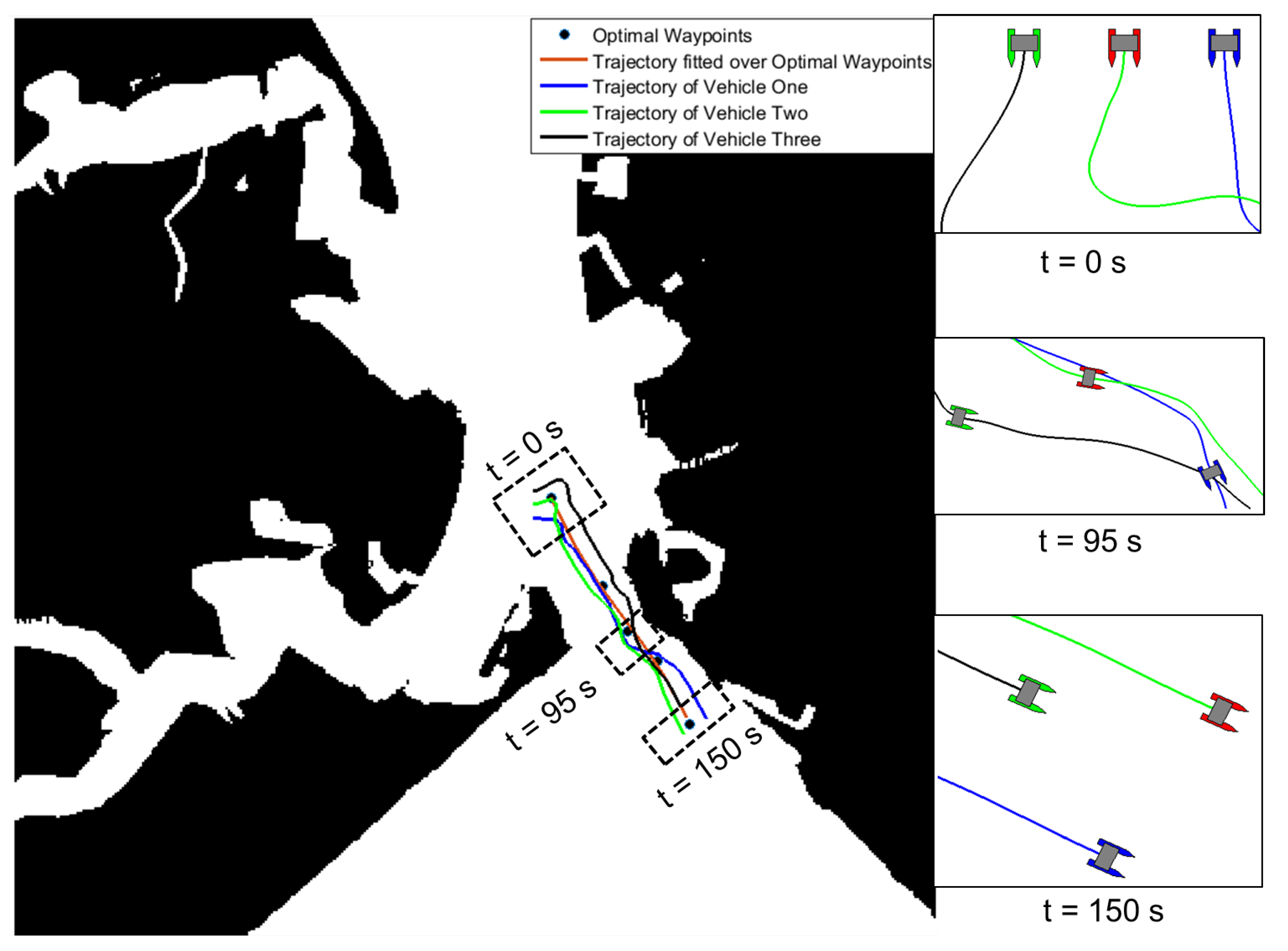
In Figure 12, the experiments were conducted for a swarm of three USVs in a practical maritime environment. The robots were initially configured by placing them parallel to each other and then the robots evolved during the motion using attractive and repulsive potential functions derived from Equation (15) which is defined as:
g a ( d ) = α g r ( d ) = β d 2 η
where d is the Euclidean distance between two robots x i x j . In addition to this, the internal collision among the vehicles was determined by the repulsive function which determined that vehicles remained at a certain distance from each other i.e., a distance of more than 2 η in all cases. This additional term has the format g c a ( d ) which is defined as:
g c a ( d ) = 2 η d d 2
which holds for the condition 0 ≤ d 2 η .
The robots had to follow the parametrised curve from Equation (1). Figure 13 shows the reference velocity profile for three USVs, where velocity of the i-th robot is x ˙ i . It should be noted that the formation centroid converged to the reference path showing that the proposed approach was effective in nature. Furthermore, in Figure 14, for each vehicle in a swarm of three USVs, the actual surge speed and heading angle (blue lines) were compared with the generated speed and orientation references (red lines); u 1 and ψ 1 correspond to the blue vehicle, u 2 and ψ 2 correspond to the green vehicle and u 3 and ψ 3 correspond to the red vehicle. It should be noted that despite the presence of oscillations in the reference signals, the tracking of surge speed and orientation by means of a dynamic controller was achieved by the proposed approach.
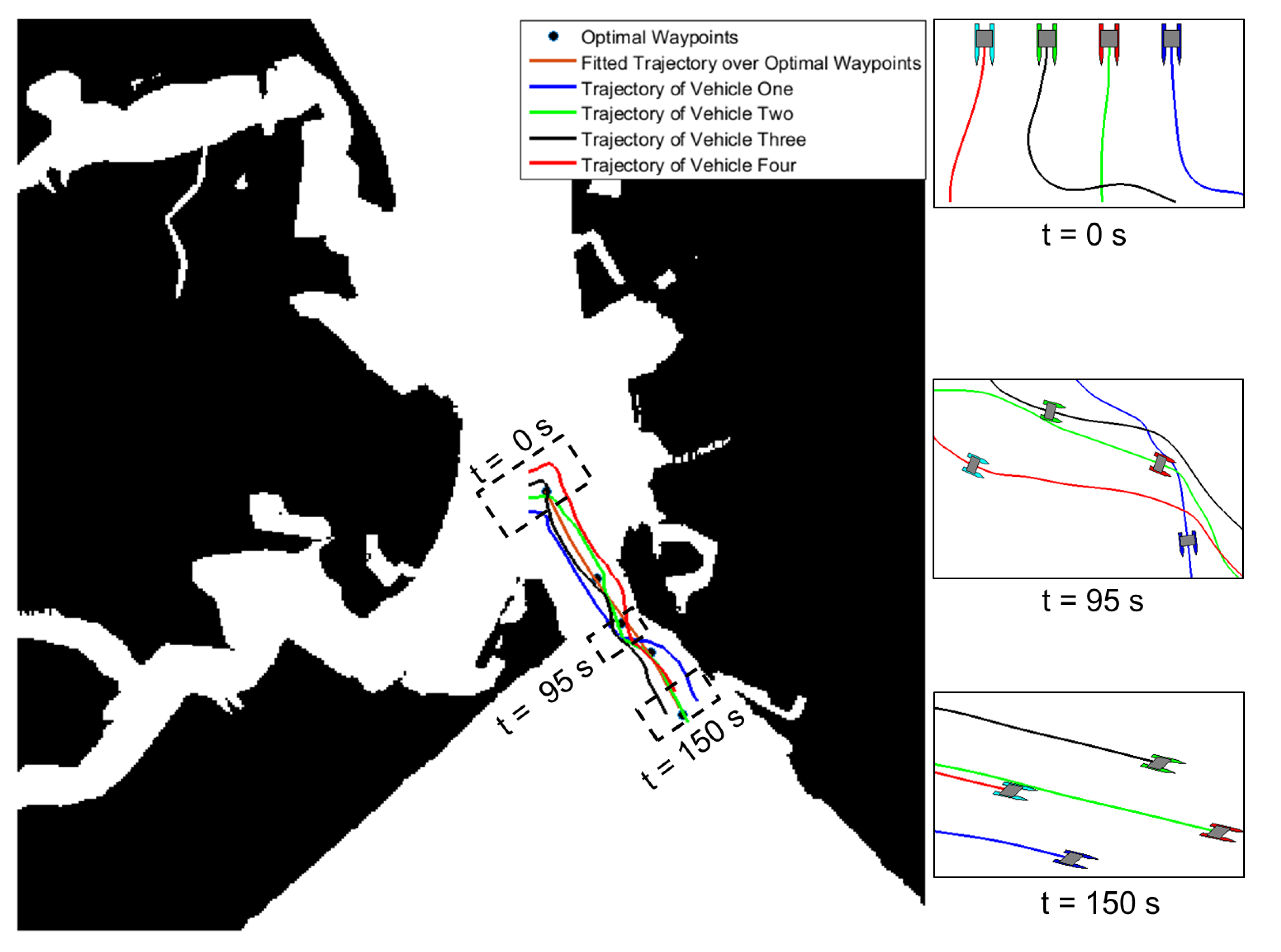
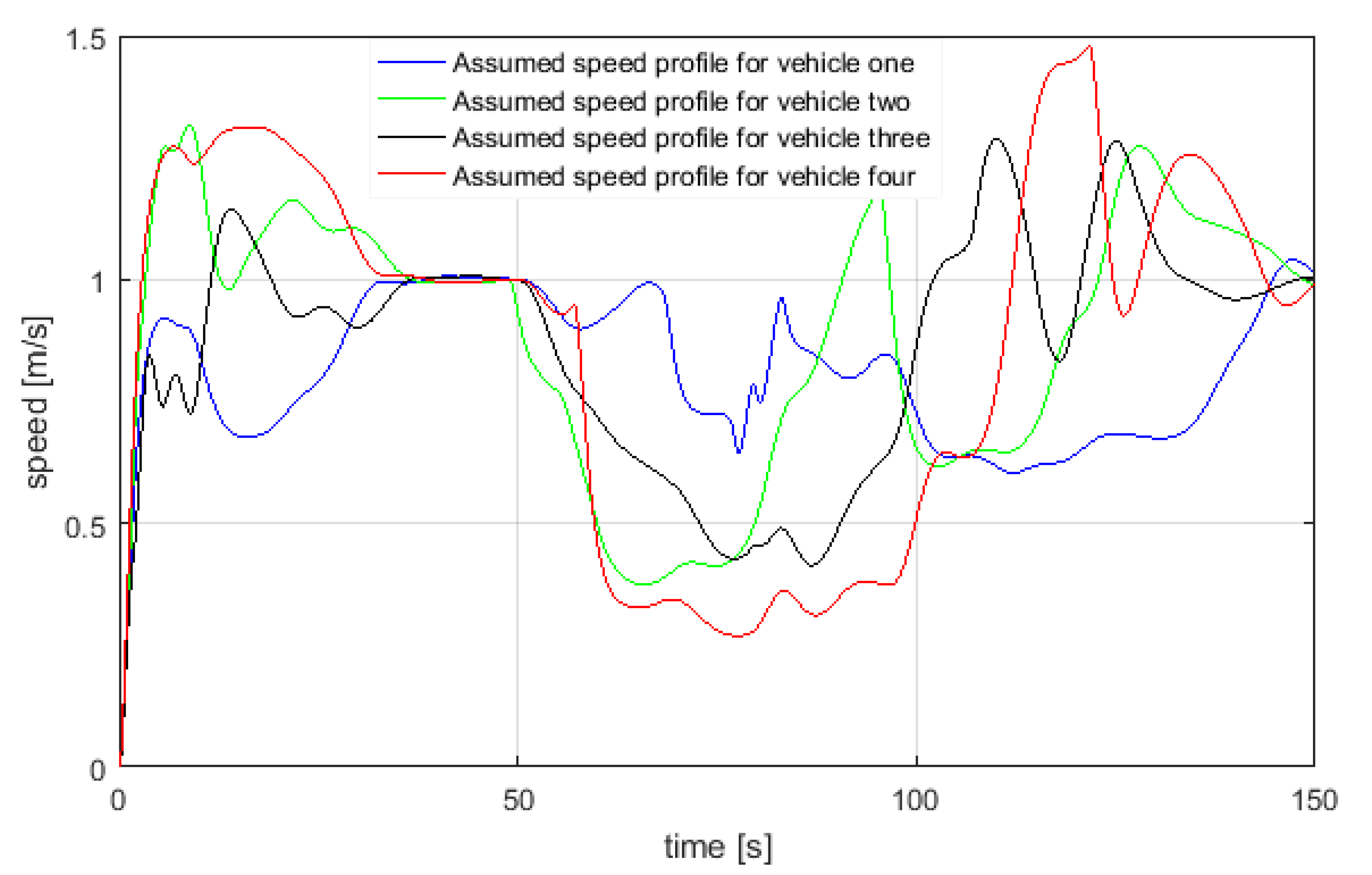
Similarly, in Figure 15, the experiments were conducted for a swarm of four USVs in a practical maritime environment to track a reference path based on the parametrised equation. Similar to Figure 13, Figure 16 shows the reference velocity profile for four USVs. Furthermore, in Figure 17, for each vehicle in a swarm of four USVs, the actual surge speed and heading angle (blue lines) were compared with the generated speed and orientation references (red lines); u 1 and ψ 1 correspond to the blue vehicle, u 2 and ψ 2 correspond to the green vehicle, u 3 and ψ 3 correspond to the black vehicle and u 4 and ψ 4 correspond to the red vehicle.
In order to ensure that complexity of the multi-USV operation in a constrained maritime environment is captured, this section reports results of three and four vehicles performing swarm aggregation and path-following from a initial parallel configuration towards a reference path generated from proposed path planner. Figure 12 and Figure 15 show the aggregation behaviour combined with motion against the reference path for three and four USVs respectively. Initial, intermediate and final positions of the formation are shown in Figure 12 and Figure 15. The reported results accounted for external collision with the shoreline into swarm evolution through attractive and repulsive functions introduced in [2]. The path-following module parameters were set to
K ρ = 1.0 ,   K ν = 0.8 ,   and   ψ a = π / 3
Collision avoidance with the shoreline was simply implemented by considering the shore profile as a set of repulsive fixed points which, within a certain distance, concur in the vehicle motion evolution. The repulsive function f ( x ) used to define the shoreline is f ( x ) = ( 5 η d i ) / d i , where d i is the Euclidean distance between the robot and the shoreline x i x s h o r e l i n e . The motion of the vehicles with respect to mutual agent interactions and to distance from the shoreline could be varied acting on the parameters of the attractive and repulsive functions. For all simulations, the values of the attraction and repulsion function parameters were set to α = 0.2, β = 1.2 and η = 3. Regarding the velocity profiles, two main issues have to be discussed:
  • The oscillations in the required velocity of each USVs were due to the swarm aggregation functions; the oscillatory behaviour could be reshaped by different definition of attraction/repulsion functions.
  • The overall guidance system took into account the physical limits of the vehicle i.e., in the current study the maximum and minimum manoeuvring speeds of scientific USVs were considered by setting the value of K s a t = 0.5.
It should be noted that formation is a function of initial position and evolution along a desired reference. In Figure 14 and Figure 17, actual surge speed and heading angle are compared with reference speed and orientation for three and four USVs framework respectively. In order to highlight the effectiveness of the combined approach, physical limits of a USV were accounted for in the guidance system by bounding the maximum and minimum manoeuvring speed between 0.2 m/s and 1.5 m/s as shown in Figure 13.

5. Conclusions and Future Work

In this study, the integration of constrained A* path planner with VT path following guidance for multi-agent USV is reported. By way of introduction, an exhaustive study of different approaches proposed in the literature has been discussed. Currently there are few works which have proposed the hybrid cooperative framework for multi USV systems.
In this context, the main contributions of the current study are summarised as follows:
  • Integration of a constrained A* approach with a decentralised VT guidance approach combined with a potential field based swarm aggregation technique for the cooperative navigation of multi USVs.
  • Combining the important features of optimal path, computational time and external collision avoidance with shoreline within the initial approach proposed by [2].
  • A constrained practical maritime environment is being considered to guide and navigate the swarm of USVs through a narrow channel on Portsmouth harbour which has not been studied till now in the literature.
  • Towards the collision avoidance with the external shoreline, a shore profile as a set of repulsive fixed points is being included in the existing approach proposed by [2] and a modified approach is proposed.
In future work, it is expected to implement the proposed approach on scientific USVs such as Springer [22] and Charlie [74] to experimentally validate the simulated methodology. In addition to that, most leading companies in USV operations are looking for the integration of COLREGs to abide the working guidelines of the International Maritime Organisation (IMO). A challenging extension of the current work lies in fact of incorporating rules of COLREGs in the current hybrid framework.

Author Contributions

Conceptualisation and methodology, Y.S. and M.B.; software, Y.S., M.B. and E.Z.; validation, Y.S.; writing—original draft preparation, Y.S., S.S., R.S. and A.K.; supervision, M.B., E.Z. and S.S.; funding acquisition, Y.S. All authors have read and agreed to the published version of the manuscript.

Funding

This research received doctoral funding from Commonwealth Scholarship Commission, UK to pursue PhD studies tenable at University of Plymouth.

Conflicts of Interest

The authors declare no conflict of interest.

Abbreviations

The following abbreviations are used in this manuscript:
ACTRESSACTor-based robots and equipment synthetic system
AOSN IIAutonomous ocean sampling network II
COLREGsInternational regulations for collision avoidance
DoDDepartment of defence
FMFast Marching
GPSGlobal positioning system
IMOInternational maritime organisation
NSBNull-Space-Based behavioural control
SOMSelf organising map
USVsUnmanned surface vehicles
VTVirtual target
VSVirtual structure

References

  1. Liu, Y.; Bucknall, R. A survey of formation control and motion planning of multiple unmanned vehicles. Robotica 2018, 36, 1–29. [Google Scholar] [CrossRef]
  2. Bibuli, M.; Bruzzone, G.; Caccia, M.; Gasparri, A.; Priolo, A.; Zereik, E. Swarm based path-following for cooperative unmanned surface vehicles. Proc. Inst. Mech. Eng. Part M J. Eng. Marit. Environ. 2014, 228, 192–207. [Google Scholar] [CrossRef]
  3. Dorigo, M.; Gambardella, L.M. Ant colony system: A cooperative learning approach to the travelling salesman problem. IEEE Trans. Evol. Comput. 1997, 1, 53–66. [Google Scholar] [CrossRef] [Green Version]
  4. Pham, D.T.; Ghanbarzadeh, A.; Koç, E.; Otri, S.; Rahim, S.; Zaidi, M. The Bees Algorithm—A Novel Tool for Complex Optimisation Problems. In Intelligent Production Machines and Systems; Elsevier: Amsterdam, The Netherlands, 2006; pp. 454–459. [Google Scholar]
  5. Parker, L.E. Current state of the art in distributed autonomous mobile robotics. In Distributed Autonomous Robotic Systems 4; Springer: Berlin/Heidelberg, Germany, 2000; pp. 3–12. [Google Scholar]
  6. Nagatani, K.; Okada, Y.; Tokunaga, N.; Kiribayashi, S.; Yoshida, K.; Ohno, K.; Takeuchi, E.; Tadokoro, S.; Akiyama, H.; Noda, I.; et al. Multirobot exploration for search and rescue missions: A report on map building in RoboCupRescue 2009. J. Field Robot. 2011, 28, 373–387. [Google Scholar] [CrossRef]
  7. Fox, D.; Ko, J.; Konolige, K.; Limketkai, B.; Schulz, D.; Stewart, B. Distributed multirobot exploration and mapping. Proc. IEEE 2006, 94, 1325–1339. [Google Scholar] [CrossRef]
  8. Huntsberger, T.; Pirjanian, P.; Trebi-Ollennu, A.; Nayar, H.D.; Aghazarian, H.; Ganino, A.J.; Garrett, M.; Joshi, S.S.; Schenker, P.S. CAMPOUT: A control architecture for tightly coupled coordination of multirobot systems for planetary surface exploration. IEEE Trans. Syst. Man Cybernet. Part A Syst. Hum. 2003, 33, 550–559. [Google Scholar] [CrossRef]
  9. Hayat, S.; Yanmaz, E.; Muzaffar, R. Survey on Unmanned Aerial Vehicle Networks for Civil Applications: A Communications Viewpoint. IEEE Commun. Surv. Tutor. 2016, 18, 2624–2661. [Google Scholar] [CrossRef]
  10. Yanmaz, E.; Yahyanejad, S.; Rinner, B.; Hellwagner, H.; Bettstetter, C. Drone networks: Communications, coordination, and sensing. Ad. Hoc. Netw. 2018, 68, 1–15. [Google Scholar] [CrossRef]
  11. Fiorelli, E.; Leonard, N.E.; Bhatta, P.; Paley, D.A.; Bachmayer, R.; Fratantoni, D.M. Multi-AUV control and adaptive sampling in Monterey Bay. IEEE J. Ocean. Eng. 2006, 31, 935–948. [Google Scholar] [CrossRef] [Green Version]
  12. Cao, X.; Zhu, D.; Yang, S.X. Multi-AUV target search based on bioinspired neurodynamics model in 3-D underwater environments. IEEE Trans. Neural Netw. Learn. Syst. 2016, 27, 2364–2374. [Google Scholar] [CrossRef]
  13. Peng, Z.; Wang, D.; Chen, Z.; Hu, X.; Lan, W. Adaptive Dynamic Surface Control for Formations of Autonomous Surface Vehicles With Uncertain Dynamics. IEEE Trans. Control. Syst. Technol. 2013, 2, 513–520. [Google Scholar] [CrossRef]
  14. Panagou, D.; Kyriakopoulos, K.J. Cooperative formation control of underactuated marine vehicles for target surveillance under sensing and communication constraints. In Proceedings of the 2013 IEEE International Conference on Robotics and Automation (ICRA), Karlsruhe, Germany, 6–10 May 2013; pp. 1871–1876. [Google Scholar]
  15. US Military. Unmanned System Integrated Roadmap; Technical Report; US Department of Defense (DoD): Washington, DC, USA, 2010. [Google Scholar]
  16. Royal Navy. Unmanned Warrior. 2016. Available online: https://www.royalnavy.mod.uk/news-and-latest-activity/operations/uk-home-waters/unmanned-warrior (accessed on 23 August 2018).
  17. Liu, Y.; Bucknall, R. Path planning algorithm for unmanned surface vehicle formations in a practical maritime environment. Ocean. Eng. 2015, 97, 126–144. [Google Scholar] [CrossRef]
  18. Zhu, D.; Huang, H.; Yang, S.X. Dynamic task assignment and path planning of multi-AUV system based on an improved self-organizing map and velocity synthesis method in three-dimensional underwater workspace. IEEE Trans. Cybern. 2013, 43, 504–514. [Google Scholar] [PubMed]
  19. Huang, H.; Zhu, D.; Ding, F. Dynamic task assignment and path planning for multi-AUV system in variable ocean current environment. J. Intell. Robot. Syst. 2014, 74, 999–1012. [Google Scholar] [CrossRef]
  20. Liu, Y.; Bucknall, R. Efficient Multi-task Allocation and Path Planning for Unmanned Surface Vehicle in Support of Ocean Operations. Neurocomputing 2018, 275, 1550–1566. [Google Scholar] [CrossRef]
  21. Ma, Y.; Zhao, Y.; Qi, X.; Zheng, Y.; Gan, R. Cooperative communication framework design for the unmanned aerial vehicles-unmanned surface vehicles formation. Adv. Mech. Eng. 2018, 10, 1–9. [Google Scholar] [CrossRef] [Green Version]
  22. Singh, Y.; Sharma, S.; Hatton, D.; Sutton, R. Optimal path planning of unmanned surface vehicles. Indian J. Geo-Mar. Sci. 2018, 47, 1325–1334. [Google Scholar]
  23. Rajendran, P.; Moscicki, T.; Wampler, J.; Shah, B.C.; von Ellenrieder, K.; Gupta, S.K. Wave-Aware Trajectory Planning for Unmanned Surface Vehicles Operating in Congested Environments. In Proceedings of the 2018 IEEE International Symposium on Safety, Security, and Rescue Robotics (SSRR), Philadelphia, PA, USA, 6–8 August 2018; pp. 1–7. [Google Scholar]
  24. Hinostroza, M.; Soares, C.G.; Xu, H. Motion Planning, Guidance and Control System for Autonomous Surface Vessel. In Proceedings of the ASME 2018 37th International Conference on Ocean, Offshore and Arctic Engineering, American Society of Mechanical Engineers, Madrid, Spain, 17–22 June 2018; p. V11BT12A016. [Google Scholar]
  25. Wang, N.; Gao, Y.; Zheng, Z.; Zhao, H.; Yin, J. A Hybrid Path-Planning Scheme for an Unmanned Surface Vehicle. In Proceedings of the 2018 Eighth International Conference on Information Science and Technology (ICIST), Cordoba, Spain, 30 June–6 July 2018; pp. 231–236. [Google Scholar]
  26. Wang, Y.; Yu, X.; Liang, X. Design and implementation of global path planning system for unmanned surface vehicle among multiple task points. Int. J. Veh. Auton. Syst. 2018, 14, 82–105. [Google Scholar] [CrossRef] [Green Version]
  27. Singh, Y.; Sharma, S.; Sutton, R.; Hatton, D.; Khan, A. Feasibility study of a constrained Dijkstra approach for optimal path planning of an unmanned surface vehicle in a dynamic maritime environment. In Proceedings of the 2018 IEEE International Conference on Autonomous Robot Systems and Competitions (ICARSC), Torres Vedras, Portugal, 25–27 April 2018; pp. 117–122. [Google Scholar]
  28. Sharma, S.K.; Sutton, R.; Motwani, A.; Annamalai, A. Non-linear control algorithms for an unmanned surface vehicle. Proc. Inst. Mech. Eng. Part J. Eng. Marit. Environ. 2014, 228, 146–155. [Google Scholar] [CrossRef] [Green Version]
  29. Chen, Y.Q.; Wang, Z. Formation control: A review and a new consideration. In Proceedings of the 2005 IEEE/RSJ International Conference on Intelligent Robots and Systems, Edmonton, AB, Canada, 2–6 August 2005; pp. 3181–3186. [Google Scholar]
  30. Kanjanawanishkul, K. Formation control of mobile robots: Survey. UBU Eng. J. 2016, 4, 50–64. [Google Scholar]
  31. Guanghua, W.; Deyi, L.; Wenyan, G.; Peng, J. Study on formation control of multi-robot systems. In Proceedings of the 2013 Third International Conference on Intelligent System Design and Engineering Applications (ISDEA), Hong Kong, China, 16–18 January 2013; pp. 1335–1339. [Google Scholar]
  32. Willcox, S.; Goldberg, D.; Vaganay, J.; Curcio, J. Multi-vehicle cooperative navigation and autonomy with the bluefin CADRE system. In Proceedings of the IFAC (International Federation of Automatic Control) Conference, Prishtina, Kosovo, 15–17 June 2006; pp. 20–22. [Google Scholar]
  33. Bellingham, J.G.; Chandler, P. Autonomous Ocean Sampling Networks II (AOSN-II): System Engineering and Project Coordination; Technical Report; Monterey Bay Aquarium Research Institute: Moss Landing, CA, USA, 2003. [Google Scholar]
  34. Aguiar, A.P.; Almeida, J.; Bayat, M.; Cardeira, B.; Cunha, R.; Häusler, A.; Maurya, P.; Oliveira, A.; Pascoal, A.; Pereira, A.; et al. Cooperative control of multiple marine vehicles theoretical challenges and practical issues. IFAC Proc. Vol. 2009, 42, 412–417. [Google Scholar] [CrossRef] [Green Version]
  35. Kalwa, J.; Pascoal, A.; Ridao, P.; Birk, A.; Glotzbach, T.; Brignone, L.; Bibuli, M.; Alves, J.; Silva, M. EU project MORPH: Current Status After 3 Years of Cooperation Under and Above Water. IFAC-PapersOnLine 2015, 48, 119–124. [Google Scholar] [CrossRef]
  36. Balch, T.; Arkin, R.C. Behavior-based formation control for multirobot teams. IEEE Trans. Robot. Autom. 1998, 14, 926–939. [Google Scholar] [CrossRef] [Green Version]
  37. Arrichiello, F.; Chiaverini, S.; Fossen, T.I. Formation control of marine surface vessels using the null-space-based behavioral control. In Group Coordination and Cooperative Control; Springer: Berlin/Heidelberg, Germany, 2006; pp. 1–19. [Google Scholar]
  38. Benjamin, M.; Leonard, J.; Curcio, J.; Newman, P. A Method for Protocol-BasedCollision Avoidance betweenAutonomous Marine SurfaceCraft. J. Field Robot. 2006, 23, 333–346. [Google Scholar] [CrossRef] [Green Version]
  39. Kumar, R.; Stover, J.A. A behavior-based intelligent control architecture with application to coordination of multiple underwater vehicles. IEEE Trans. Syst. Man Cybern. Part Syst. Hum. 2000, 30, 767–784. [Google Scholar] [CrossRef]
  40. Rosenblatt, J.; Williams, S.; Durrant-Whyte, H. A behavior-based architecture for autonomous underwater exploration. Inf. Sci. 2002, 145, 69–87. [Google Scholar] [CrossRef]
  41. Das, A.K.; Fierro, R.; Kumar, R.V.; Ostrowski, J.P.; Spletzer, J.; Taylor, C.J. A vision-based formation control framework. IEEE Trans. Robot. Autom. 2002, 18, 813–825. [Google Scholar] [CrossRef] [Green Version]
  42. Skjetne, R.; Moi, S.; Fossen, T.I. Nonlinear formation control of marine craft. In Proceedings of the 2002 41st IEEE Conference on Decision and Control, Las Vegas, NV, 10–13 December 2002; Volume 2, pp. 1699–1704. [Google Scholar]
  43. Breivik, M.; Hovstein, V.E.; Fossen, T.I. Ship formation control: A guided leader-follower approach. IFAC Proc. Vol. 2008, 41, 16008–16014. [Google Scholar] [CrossRef] [Green Version]
  44. Peng, Z.; Wang, D.; Hu, X. Robust adaptive formation control of underactuated autonomous surface vehicles with uncertain dynamics. IET Control. Theory Appl. 2011, 5, 1378–1387. [Google Scholar] [CrossRef]
  45. Jin, X. Fault tolerant finite-time leader-follower formation control for autonomous surface vessels with LOS range and angle constraints. Automatica 2016, 68, 228–236. [Google Scholar] [CrossRef]
  46. Liu, Y.; Bucknall, R. The angle guidance path planning algorithms for unmanned surface vehicle formations by using the fast marching method. Appl. Ocean. Res. 2016, 59, 327–344. [Google Scholar] [CrossRef] [Green Version]
  47. Edwards, D.; Bean, T.; Odell, D.; Anderson, M. A leader-follower algorithm for multiple AUV formations. In Proceedings of the 2004 IEEE/OES Autonomous Underwater Vehicles, Sebasco, Maine, 17–18 June 2004; pp. 40–46. [Google Scholar]
  48. Cui, R.; Ge, S.S.; How, B.V.E.; Choo, Y.S. Leader–follower formation control of underactuated autonomous underwater vehicles. Ocean. Eng. 2010, 37, 1491–1502. [Google Scholar] [CrossRef]
  49. Cui, R.; Ge, S.S.; How, B.V.E.; Choo, Y.S. Leader-follower formation control of underactuated auvs with leader position measurement. In Proceedings of the 2009 ICRA’09 IEEE International Conference on Robotics and Automation, Kobe, Japan, 12–17 May 2009; pp. 979–984. [Google Scholar]
  50. Li, S.; Wang, X. Finite-time consensus and collision avoidance control algorithms for multiple AUVs. Automatica 2013, 49, 3359–3367. [Google Scholar] [CrossRef]
  51. Peng, Z.; Wang, D.; Shi, Y.; Wang, H.; Wang, W. Containment control of networked autonomous underwater vehicles with model uncertainty and ocean disturbances guided by multiple leaders. Inf. Sci. 2015, 316, 163–179. [Google Scholar] [CrossRef]
  52. Xing, W.; Zhao, Y.; Karimi, H.R. Convergence analysis on multi-AUV systems with leader-follower architecture. IEEE Access 2017, 5, 853–868. [Google Scholar] [CrossRef] [Green Version]
  53. Rout, R.; Subudhi, B. A backstepping approach for the formation control of multiple autonomous underwater vehicles using a leader–follower strategy. J. Mar. Eng. Technol. 2016, 15, 38–46. [Google Scholar] [CrossRef] [Green Version]
  54. Yang, E.; Gu, D. Nonlinear formation-keeping and mooring control of multiple autonomous underwater vehicles. IEEE/ASME Trans. Mech. 2007, 12, 164–178. [Google Scholar] [CrossRef]
  55. Tan, K.H.; Lewis, M.A. Virtual structures for high-precision cooperative mobile robotic control. In Proceedings of the IROS 96 1996 IEEE/RSJ International Conference on Intelligent Robots and Systems’ 96, Osaka, Japan, 8 November 1996; Volume 1, pp. 132–139. [Google Scholar]
  56. Ren, W.; Beard, R. Decentralized scheme for spacecraft formation flying via the virtual structure approach. J. Guid. Control. Dyn. 2004, 27, 73–82. [Google Scholar] [CrossRef]
  57. Lewis, M.A.; Tan, K.H. High precision formation control of mobile robots using virtual structures. Auton. Robot. 1997, 4, 387–403. [Google Scholar] [CrossRef]
  58. Mehrjerdi, H.; Ghommam, J.; Saad, M. Nonlinear coordination control for a group of mobile robots using a virtual structure. Mechatronics 2011, 21, 1147–1155. [Google Scholar] [CrossRef]
  59. Do, K. Formation control of underactuated ships with elliptical shape approximation and limited communication ranges. Automatica 2012, 48, 1380–1388. [Google Scholar] [CrossRef] [Green Version]
  60. Khatib, O. Real Time Obstacle Avoidance for Manipulators and Mobile Robots. Int. J. Robot. Res. 1986, 5, 90–98. [Google Scholar] [CrossRef]
  61. Zhang, M.; Shen, Y.; Wang, Q.; Wang, Y. Dynamic artificial potential field based multi-robot formation control. In Proceedings of the Instrumentation and Measurement Technology Conference (I2MTC), Austin, TX, USA, 3–6 May 2010; pp. 1530–1534. [Google Scholar]
  62. Ge, S.S.; Fua, C.H. Queues and artificial potential trenches for multirobot formations. IEEE Trans. Robot. 2005, 21, 646–656. [Google Scholar] [CrossRef]
  63. Paul, T.; Krogstad, T.R.; Gravdahl, J.T. Modelling of UAV formation flight using 3D potential field. Simul. Model. Pract. Theory 2008, 16, 1453–1462. [Google Scholar] [CrossRef]
  64. Wang, J.; Wu, X.B.; Xu, Z.L. Decentralized formation control and obstacles avoidance based on potential field method. In Proceedings of the 2006 International Conference on Machine Learning and Cybernetics, Guangzhou, China, 18–21 August 2006; pp. 803–808. [Google Scholar]
  65. Huang, H.; Tang, Q.; Zhang, G.; Wan, L.; Qin, H. A novel approach to integrate potential field and interval type-2 fuzzy learning for the formation control of multiple autonomous underwater vehicles. Adv. Mech. Eng. 2017, 9, 1687814017737447. [Google Scholar] [CrossRef] [Green Version]
  66. Das, B.; Subudhi, B.; Pati, B.B. Co-operative control of a team of autonomous underwater vehicles in an obstacle-rich environment. J. Mar. Eng. Technol. 2016, 15, 135–151. [Google Scholar] [CrossRef]
  67. Mei, J.H.; Arshad, M. A hybrid artificial potential field method for autonomous surface vessel path planning in dynamic riverine environment. Indian J. Geo-Mar. Sci. 2015, 44, 1980–1994. [Google Scholar]
  68. Zhai, H.; Ji, Z.; Gao, J. Formation control of multiple robot fishes based on artificial potential field and leader-follower framework. In Proceedings of the 2013 25th Chinese, Control and Decision Conference (CCDC), Guiyang, China, 25–27 May 2013; pp. 2616–2620. [Google Scholar]
  69. Liu, C.L.; Tian, Y.P. Formation control of multi-agent systems with heterogeneous communication delays. Int. J. Syst. Sci. 2009, 40, 627–636. [Google Scholar] [CrossRef]
  70. Ren, W. Consensus based formation control strategies for multi-vehicle systems. In Proceedings of the 2006 American Control Conference, Minneapolis, MN, USA, 14–16 June 2006. [Google Scholar]
  71. Krick, L. Application of gRaph Rigidity in Formation Control of Multi-Robot Networks. Ph.D. Thesis, University of Toronto, Toronto, ON, Canada, 2007. [Google Scholar]
  72. Singh, Y.; Sharma, S.; Sutton, R.; Hatton, D.; Khan, A. A constrained A* approach towards optimal path planning for an unmanned surface vehicle in a maritime environment containing dynamic obstacles and ocean currents. Ocean. Eng. 2018, 169, 187–201. [Google Scholar] [CrossRef] [Green Version]
  73. Gazi, V.; Passino, K.M. Stability analysis of swarms. IEEE Trans. Autom. Control. 2003, 48, 692–697. [Google Scholar] [CrossRef] [Green Version]
  74. Bibuli, M.; Bruzzone, G.; Caccia, M.; Lapierre, L. Path-following algorithms and experiments for an unmanned surface vehicle. J. Field Robot. 2009, 26, 669–688. [Google Scholar] [CrossRef] [Green Version]
Figure 1. Factors associated with formation control and cooperative motion planning (Source: modified from [1]).
Jmse 08 00624 g001
Figure 3. Generic architecture of a multiple vehicle system (Source: modified from [1]).
Jmse 08 00624 g003
Figure 4. Comparison of formation control strategies (Source: modified from [31]).
Jmse 08 00624 g004
Figure 5. Two robots using basic leader-following controller (Source: [41]).
Jmse 08 00624 g005
Figure 6. Three robots using basic leader-following controller (Source: [41]).
Jmse 08 00624 g006
Figure 7. Schematic of the Virtual Structure (VS) approach for a three robot framework.
Jmse 08 00624 g007
Figure 8. Schematic of integrated path planning, guidance system and swarm aggregation approach.
Jmse 08 00624 g008
Figure 9. A schematic showing the path generated by a conventional grid based path planner compared against the path generated by a grid based path planner by considering safety distance and sea surface currents (clockwise). In case of anti clockwise currents, the sea surface currents push the USV towards the obstacle and the proposed algorithm makes sure that a safety distance is maintained to ensure no collision [72].
Jmse 08 00624 g009
Figure 10. Generated (left) and smoothed trajectory (right) from the optimal waypoints produced by the path planner. Binary map of 800 × 800 resolution is considered for the current study with one pixel representing 3.6 m on a real map.
Jmse 08 00624 g010
Figure 11. Frame definitions for path following algorithm based on a VT approach.
Jmse 08 00624 g011
Figure 12. USV motions during swarm aggregation combined with path-following guidance for three USVs.
Jmse 08 00624 g012
Figure 13. USV speed profiles assumed during swarm aggregation evolution for three USVs.
Jmse 08 00624 g013
Figure 14. USV speed and heading profiles during swarm aggregation combined with path-following guidance for three USVs.
Jmse 08 00624 g014
Figure 15. USV motions during swarm aggregation combined with path-following guidance for four USVs.
Jmse 08 00624 g015
Figure 16. USV speed profiles assumed during swarm aggregation evolution for four USVs.
Jmse 08 00624 g016
Figure 17. USV speed and heading profiles during swarm aggregation combined with path-following guidance for four USVs.
Jmse 08 00624 g017
Table 1. Chosen optimal waypoints (WPs) from path planner.
StartWP 1WP 2WP 3Goal
x (pixels)238261272285299
y (pixels)212251271284312