Article

Numerical Investigation of Shallow Liquid Sloshing in a Baffled Tank and the Associated Damping Effect by BM-MPS Method

1
College of Marine Science and Engineering, Nanjing Normal University, Nanjing 210046, China
2
College of Harbor, Coastal and Offshore Engineering, Hohai University, Nanjing 210024, China
*
Authors to whom correspondence should be addressed.
J. Mar. Sci. Eng. 2021, 9(10), 1110; https://doi.org/10.3390/jmse9101110
Submission received: 6 September 2021 / Revised: 10 October 2021 / Accepted: 11 October 2021 / Published: 12 October 2021
(This article belongs to the Section Ocean Engineering)

Abstract

:
Understanding the damping mechanism of baffles is helpful to make more reasonable use of them in suppressing liquid sloshing. In this study, the damping effect and mechanism of vertical baffles in shallow liquid sloshing under a rotational excitation are investigated by an improved particle method. By incorporation of a background mesh scheme and a modified pressure gradient model, the accuracy of impact pressure during sloshing is significantly enhanced. Combined with the advantages of the particle method, the present numerical method is a wonderful tool for the investigation of liquid sloshing issues. Through the analysis of impact pressure, the influences of baffle height and baffle position on the damping mechanism are discussed. The results show that the damping effect of vertical baffles increases with the increase of the elevation of baffle top and decreases with the increase of the elevation of the baffle bottom. Moreover, the resonance characteristics of sloshing are altered when static water is divided into two parts by the vertical baffle. The dominant damping mechanism of vertical baffles depends on the configurations.

1. Introduction

Liquid sloshing is a common phenomenon in the transportation of liquid cargo ships. When the frequency of the external load is close to the resonance frequency of the tank, the sloshing is extremely violent [1,2,3,4]. The force generated by violent sloshing would lead to the instability of ships, and the impact pressure on the tank wall could damage the tank structure, leading to the leakage of liquid. With the rapid development of large-scale liquid cargo ships, more and more attention has been paid to the use of baffles to restrain liquid sloshing. In order to make baffles more effective at suppressing sloshing, it is necessary to figure out the damping mechanism of baffles under different conditions.
For the rational utilization of anti-slosh baffles, a mass of work has been done experimentally and numerically to investigate the effect of baffles on restraining sloshing. Compared with a horizontal baffle, a vertical baffle is more effective in reducing the sloshing amplitude, especially in shallow water [5,6,7].
Akyildız and Erdem [6] pointed out that when liquid overtopped the vertical baffle in shallow sloshing, a shear layer was produced and the energy was dissipated by the viscous action. Younes et al. [8] carried out an experimental investigation of hydrodynamic damping due to vertical baffles in a partially filled rectangular tank. The results showed the damping effect increased with the increase of the height for the lower mounted baffle, and the damping ratio is proportional to the number of baffles. Based on the wide investigation of vertical baffles on restraining sloshing, Faltinsen and Timokha [9] gave the analytical solution of the natural frequency of sloshing with the specific baffle type, which is a function of baffle height. Panigrahy et al. [10] revealed that the vortex generation at the sharp boundary of baffle contributed to the decrease of impact pressure through the experiment of combined baffles.
Jung et al. [11] discussed the effect of vertical baffle height on the liquid sloshing in a lateral moving rectangular tank based on the VOF method. The results revealed that with the increase of baffle height, the vortex generated by the baffle tip became weaker and smaller, while the augmentation of the blockage effect of the baffle (i.e., hydrodynamic damping) contributed to the reduction of sloshing. Nayak and Biswal [4] compared the hydrodynamic damping of three different configurations under lateral excitation by experiments. The presence of internal objects decreased the resonance frequency of sloshing and the decrease was monotonic with the increase in the baffle height. Xue et al. [3] studied the liquid sloshing in a tank with vertical baffles of different configurations under horizontal excitation. They found that the variation tendency of the first mode natural frequency is different for the vertical baffles with different configurations. Through the study of liquid sloshing in a rectangular tank with a vertical slotted porous screen under a lateral forced motion, Poguluri and Cho [12] put forward a synergetic approach for the parametric investigation of sloshing. Yu et al. [13] experimentally investigated the damping effect and mechanism of vertical baffles under a vertical excitation. Tang et al. [14] numerically studied the liquid sloshing with unequal baffle height allocation schemes. Kamath et al. [15] investigated the effect of vertical baffles in sloshing at shallow liquid depths by a RANS model.
According to the aforementioned studies, it is summarized that the damping mechanism of the vertical baffle can be broadly divided into three types: (1) the dissipation of fluid energy in the form of vortex damping at the tip of baffles (vortex damping); (2) the scale change of the tank; (3) the blockage effect of the baffle (hydrodynamic damping). Meanwhile, configurations of baffles (especially baffle height, location, number, etc.) have an important role in the damping effect. Despite these achievements, there are still some issues that need to be explored. For example, most of the parametric investigations on baffle configurations are conducted under horizontal excitation. If baffle parameters keep the same, but the external excitation form is changed, whether the baffle damping law is consistent remains to be investigated. Another question is which damping mechanism dominates for baffles of different configurations. Therefore, this study will focus on these questions.
As a representative example of free surface flow with large deformation, liquid sloshing is an intrinsic nonlinear problem. As for the simulation of this kind of fluid motion, particle methods based on the Lagrangian description have an essential advantage. The famous particle methods, such as the famous Smoothed Particle Hydrodynamics (SPH) method [16] and Moving Particle Semi-implicit (MPS) method [17], have been widely applied in the simulation of liquid sloshing [18,19,20,21]. For example, Delorme et al. [22] studied the pressure fields in the case of shallow water sloshing by SPH method. Zheng et al. [23] discussed the effectiveness of baffles of different configurations by an incompressible SPH method. Khayyer et al. [24] conducted the simulation of liquid sloshing with an elastic baffle by a multi-resolution MPS method. Zhang et al. [25] simulated the sloshing process of a 2-D damaged ship section using an improved MPS method.
In this study, an improved MPS method is adopted to simulate the liquid sloshing in a 2-D rectangular baffled tank forced by a rotational motion with a large excitation amplitude. To enhance the calculation precision of impact pressure, a new calculation mode for the source term of Poison equation is applied in the present method, in which a background mesh is incorporated to reduce the numerical noise resulting from the spatial discontinuity in the calculated source term. Hence, the improved MPS method is called the BM-MPS method. Varying baffle arrangement and height, six types of vertical baffles are employed to investigate the damping effect of baffles. Based on the analyses of impact pressure and velocity fields, the influence of baffle configurations on the damping mechanism is emphatically discussed, especially for surface-flushing and surface-piercing baffles. According to the above, the paper is organized as follows. The algorithm of the BM-MPS method is described in Section 2. The validation of the present method and the discussion on the damping effect and mechanism are presented in Section 3. Finally, a brief summary and conclusion of the study is shown in Section 4.

2. BM-MPS Method

2.1. Basic Algorithm of MPS Method

In the MPS method, the governing equations of the motion of fluid flows are the Lagrangian continuity and Navier-Stoke equations, which can be expressed as follows:
1 ρ D ρ D t + u = 0 ,
D u D t = 1 ρ p + ν 2 u + g ,
where u is the velocity vector, t is the time, ρ is the density of fluid, p is the pressure, ν is the kinematic viscosity coefficient, and g is the gravitational acceleration. The change in the density of fluid with time, Dρ/Dt, is zero for an incompressible fluid.
Following the theory of Helmholtz-Leray decomposition, a two-step projection algorithm is applied to separately calculate the velocity and pressure at each calculation time step. In the first step, only the gravity and viscous force terms in the momentum equation are calculated, and then temporary velocity and position vectors are obtained.
u i * = u i k + Δ t ( ν 2 u + g ) ,
r i * = r i k + Δ t u i * ,
where the superscript * indicates the intermediate value at the prediction step, k denotes the calculation time step number, and ∆t symbolizes the time step size.
Using the assumption of density invariance for incompressible fluids, a pressure Poisson equation (PPE) is derived by Koshizuka and Oka [17] for the update of the pressure field.
Δ t ρ 2 p i k + 1 = 1 n 0 ( D n D t ) i * = 1 n 0 n i * n 0 Δ t ,
where n is named the particle number density, a normalization factor which is equivalent to the fluid density ρ in the MPS method, and n0 represents the initial particle number density. The particle number density n is defined as:
n i = j i w i j , w i j = { r e r i j 1           0 r i j < r e 0                                 r e r i j ,
where w is the kernel function, and the standard MPS kernel function is chosen in this study. Here, rij is the distance between two arbitrary particles, rij = |rjri|, and re is the radius of the influential domain, re = 2.4l0, with l0 symbolizing the initial particle spacing.
After solving the PPE, the new pressure field is obtained. The new pressure value is taken into the pressure gradient operator, and then the temporary velocity and position are updated.
u i k + 1 = u i * Δ t p k + 1 ρ ,
r i k + 1 = r i k + Δ t u i k + 1 ,

2.2. BM-Scheme for the Calculation of Source Term of PPE

The source term of PPE has a significant influence on the pressure calculation. Different from the original source term form in Equation (5), an improved source term is preferred in the BM-MPS method, and then the expression of PPE is written as:
Δ t ρ 2 p i k + 1 = ( 1 - γ ) 1 n 0 j i ( r e r i j 3 ( u j u i ) ( r j r i ) ) * + 1 n 0 γ n i * n 0 Δ t ,
in which γ is an empirical parameter (γ = 0.01).
The first term on the right hand of Equation (9) is the dominant part of the source term, which is the expression of the higher-order source term (HS) proposed by Khayyer and Gotoh [26]. The Dn/Dt is discretized as the velocity divergence form in the HS. The second term is the original source term form, which is considered to preserve fluid volume conservation.
There is a significant requirement for the accuracy of pressure calculation in the sloshing simulation. Therefore, the background mesh scheme (BM) is applied for the calculation of source term in the present numerical method, which mainly aims at the first term of the source term in Equation (9). The BM scheme can increase spatial continuity in between calculated source terms at moving particle positions through the utilization of background mesh information, and this enhances the accuracy of pressure calculation.
Under the framework of the BM scheme, the first term of the source term is no longer calculated directly on discrete particles but is interpolated from mesh nodes. In the BM scheme, the velocities of discrete particles are first assigned to the background mesh nodes:
u M = i u i w w e n d ( r i M , r e M ) i w w e n d ( r i M , r e M ) , i r i M = | r i r M | r e M ,
where M stands for a mesh node, i represents a particle, riM is the distance between a particle and a mesh node, and reM denotes the radius of the influential region for mesh nodes. In addition, wwend symbolizes the considered Wendland kernel function.
Subsequently, the first term of Equation (9) on the mesh nodes was calculated:
1 n 0 j i ( r e r i j 3 ( u j u i ) ( r j r i ) ) * 1 n 0 M j M i ( r e r M i M j 3 ( u M j u M i ) ( r M j r M i ) ) .
Finally, the source term value was extrapolated for each target particle from its nearest mesh nodes:
S T i = S T M w w e n d ( r i M ) w w e n d ( r i M ) ,
where STM represents the value of source term calculated on the background mesh node. About the detailed explanation for the BM scheme, please refer to reference [27].

2.3. A high-Order Pressure Gradient Model

In addition to the above-mentioned modifications, an improved pressure gradient discretization model derived from Taylor series expansion is employed in the present method, which has first-order accuracy. The expression of the improved gradient model is:
p i = { C i 1 [ 1 n 0 i j p j p ^ i r i j 2 ( r j r i ) w i j ] ,       | C i | α c D s n 0 i j p j p ^ i r i j 2 ( r j r i ) w i j ,                                 | C i | < α c ,
C i = [ 1 n 0 i j w i j ( r j r i ) r i j ( r j r i ) T r i j ] p ^ i = min j J ( p i , p j ) ,       J = { j : w ( r i j ) 0 }
where p ^ i is the minimum pressure value in the influence domain of the target particle i, which contributes to mitigate particle clustering and improve the stability of pressure calculation. Considering the special case of non-inverse Ci caused by particle splashing, the original pressure gradient model (the second equation in Equation (13)) is coupled in the new model. For convenience, this model is named the Combined pressure Gradient Model (CGM) [28].

2.4. Boundary Conditions

In the MPS method, the free surface can be easily identified through the calculation of particle number density, exploiting the fact that the truncation of kernel function exists near the free surface. The original criterion for identifying free surface particles is defined as:
n i < β n 0 ,
where β is a coefficient ranging from 0.8 to 0.97, and β = 0.97 is generally used [29].
Nevertheless, the original surface detection criterion often results in free surface particle misrecognition. Hence, a complementary recognition condition for free surface particles is considered in the BM-MPS method, which is defined as [30]:
A i = j i | r j r i | l 0 w ( r i j ) A i < α A 0 ,       α < 1.0
where Ai symbolizes the filling rate, the percentage of the influence domain of target particle i covered by its surrounding particles, and A0 is the filling rate of inner particles at the initial moment. In this study, the value of α is chosen as 0.88.
As for the solid wall boundary, it is represented by wall particles and dummy particles [29]. Wall particles will take part in the calculation of pressure and the judgement of free surface while the dummy particles are only accounted in the calculation of particle number density. In this study, one layer of wall particles and two layers of dummy particles are arranged along the tank borders, and three layers of wall particles are used to represent the baffle.

3. Results

3.1. Calculation Conditions

The liquid sloshing induced by rotational excitation is studied to investigate the damping mechanism of vertical baffles by the BM-MPS method. The basic calculation conditions are consistent with those in the experiment conducted by Delorme et al. Figure 1 presents a schematic diagram of the computational domain and illustrates the specific simulation conditions. The size of the tank is 0.9 m long and 0.58 m high with 0.093 m water depth. Near the free surface, a pressure calculation point is set on the left lateral boundary of the tank to record the impact pressure during liquid sloshing. The rotation center is located at the point O 0.184 m from the bottom boundary along the perpendicular bisector of the tank (Figure 1). The tank is forced by a sinusoidal rotating motion, and the excitation equation is as follows:
θ = θ max sin ( ω t ) ,
where θmax is the maximum rotation angle, 0.07 rad; ω is the excitation frequency.
According to the linear analytical solution based on the potential flow theory by Faltinsen (1978) [31], the natural frequency of a 2-D sloshing in a rectangular tank can be computed as:
ω n 2 = g ( 2 n + 1 ) π L tanh { ( 2 n + 1 ) π L h } , T n = 2 π ω n ,
in which L symbolizes the length of the tank, h indicates the water depth, and n is the mode number. In this study, the lowest natural frequency of fluid in the tank is calculated as ω0 = 3.277 s−1, and the corresponding period is T0 = 1.917 s.
As shown in Figure 1, the vertical baffle is in the middle of the tank. HB symbolizes the distance between the top of the baffle to the bottom of the tank, while HS represents the interspace between the baffle to the tank. Hence, the baffle height equals to HBHS. In terms of different combinations of HB/h0 and HS/h0, six cases are considered to investigate the influence of baffle height and vertical arrangement on the damping effect and mechanism of vertical baffles, as shown in Figure 2. Here, HB/h0 < 1 means that the baffle is immersed in the water, and vice versa. HS/h0 = 0, is referred to as a bottom-mounted type, and the other is known as a wall-mounted baffle.
As for the numerical model parameters, the initial particle spacing l0 is set as 0.003 m to guarantee the precision of results. The time step size is determined based on the Courant-Friedrichs-Lewy (CFL) stability condition and a maximum allowable time step size of Δtmax = 0.0003 s. The fluid’s kinematic viscosity and density are set equivalent to those of water, corresponding to the experiment, i.e., ν = 10−6 m2/s, ρ = 1000 kg/m3, respectively. The sloshing motion is simulated from the hydrostatic state according to Equation (17).

3.2. Sloshing Simulated by BM-MPS

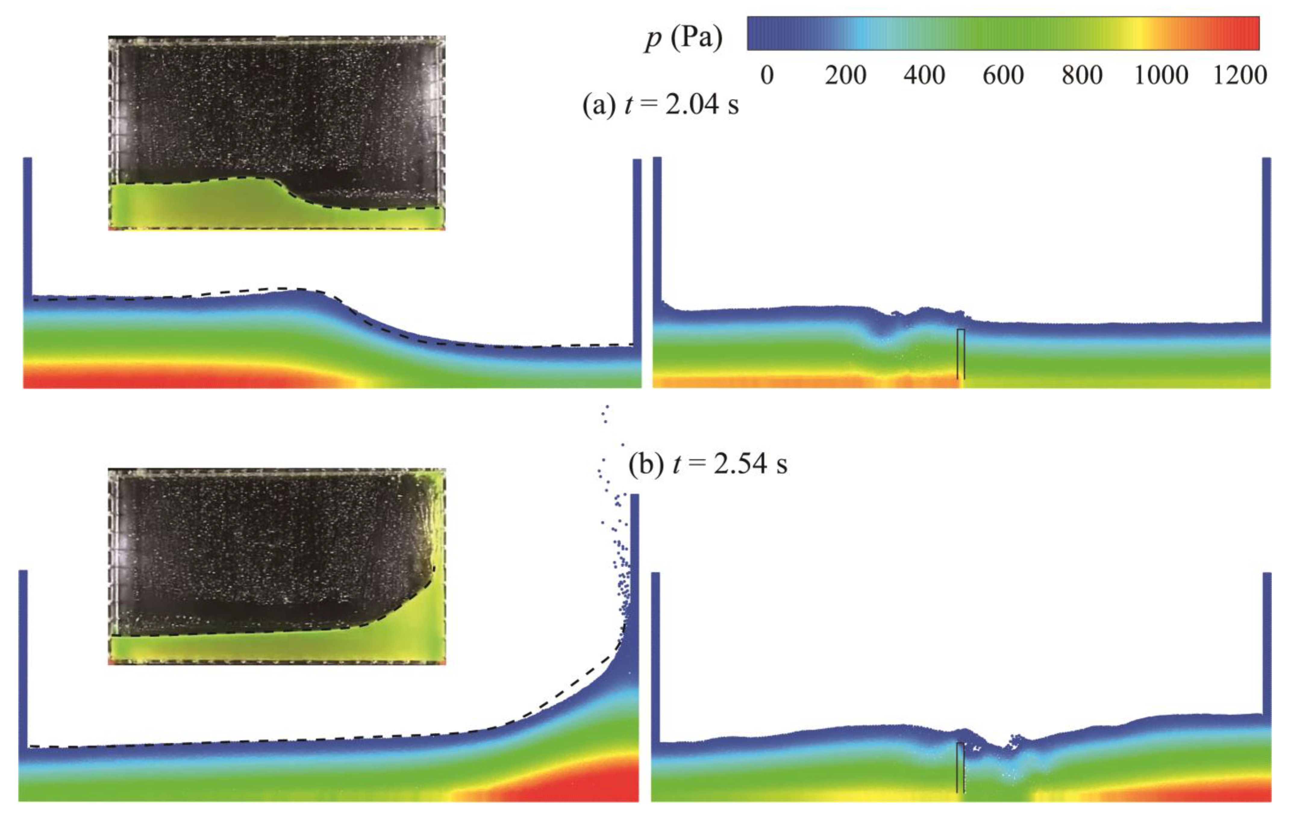
Figure 3 shows the snapshots of sloshing motion in the tank without and with a vertical baffle simulated by the BM-MPS method under the excitation period T = 1.91 s (ω/ω0 = 1.004). The fluid motion patterns and pressure fields at four different moments are clearly exhibited. The left snapshots in Figure 3 are the results without a baffle, and the corresponding images of the experiment done by Delorme et al. (2009) [22] are presented to validate the numerical results. The snapshots indicate that the generation of the wave, the water climbing up, the wave breaking and impacting the tank during the sloshing process are all clearly reproduced, and agree with the experiment results well. The right snapshots show the liquid sloshing in the tank with an immersed bottom-mounted vertical baffle (HB/h0 = 0.8). Water mixes near the bulkhead violently and the amplitude of liquid sloshing is significantly diminished. The comparison of results between the two groups clearly displays the damping effect achieved by the vertical baffle.
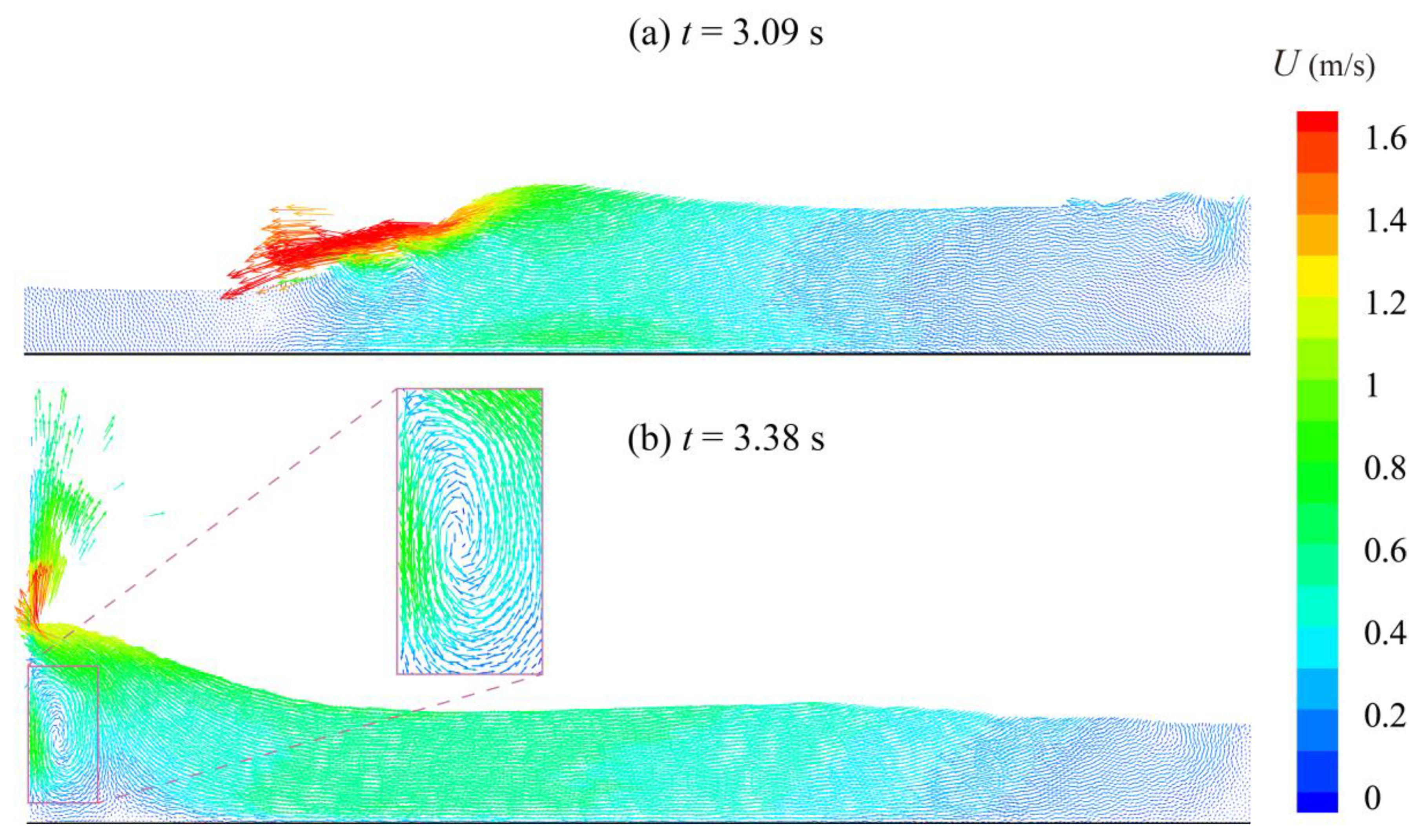
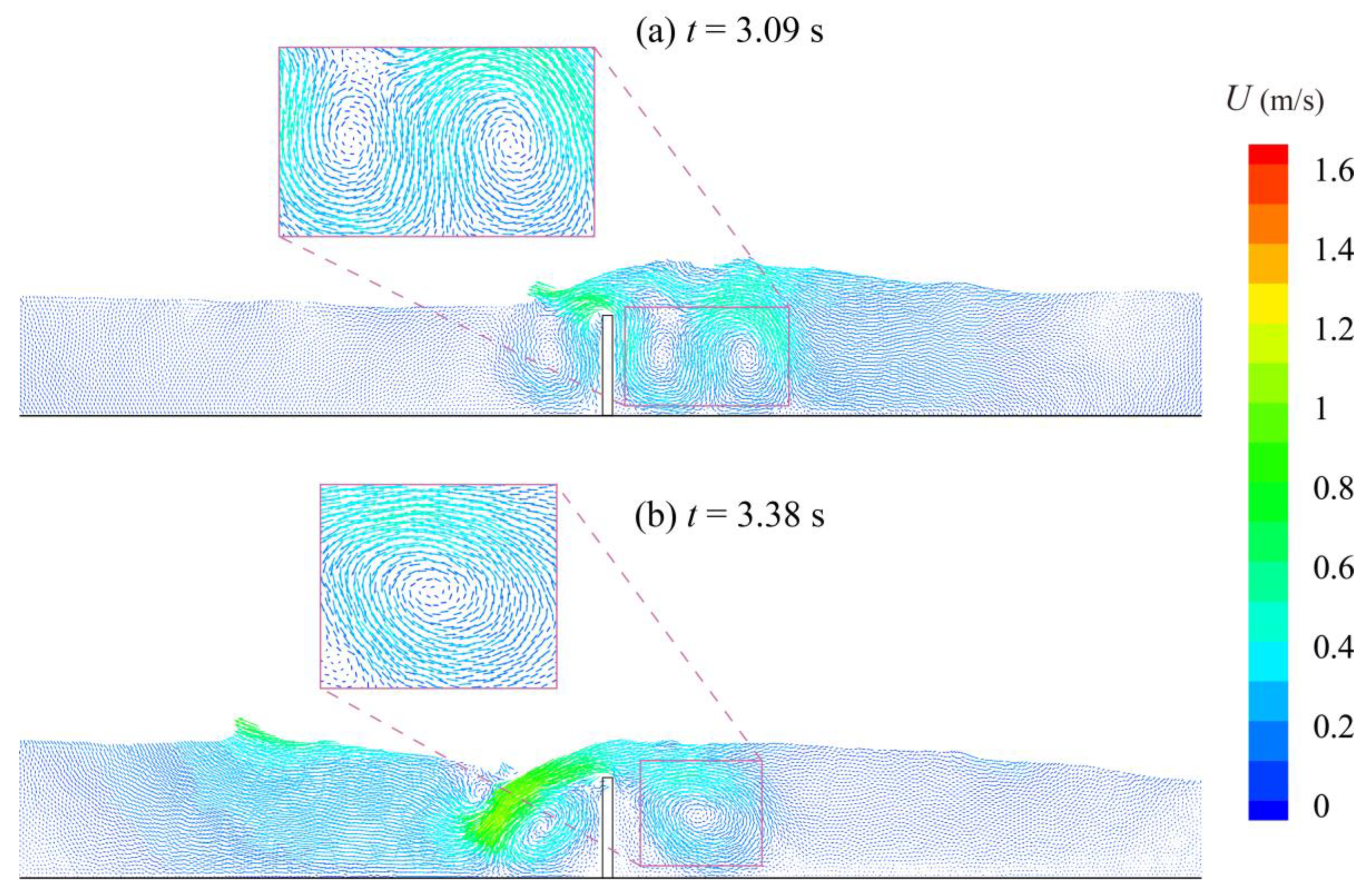
Figure 4 and Figure 5 describe the velocity fields at the moments t = 3.09 s and t = 3.38 s without and with a vertical baffle, respectively. The magnitude of velocity, U = (u2 + v2)0.5, is represented by color. In Figure 4, the maximum value of the velocity is more than 1.6 m/s. The shape of the breaking wave is obvious and only individual vortices appear near the lateral boundaries. However, different from the velocity fields without a baffle, several remarkable vortices generated from the hydraulic jump appear on both sides of the baffle in Figure 5. These vortices force part of water to move around the baffle to mitigate sloshing. In addition, compared to the velocity in Figure 4, the magnitude of velocity decreases overall and the kinetic energy of the water is concentrated near the baffle. The damping mechanism of a vertical baffle by turbulent energy dissipation is well proved by the comparison of velocity fields.
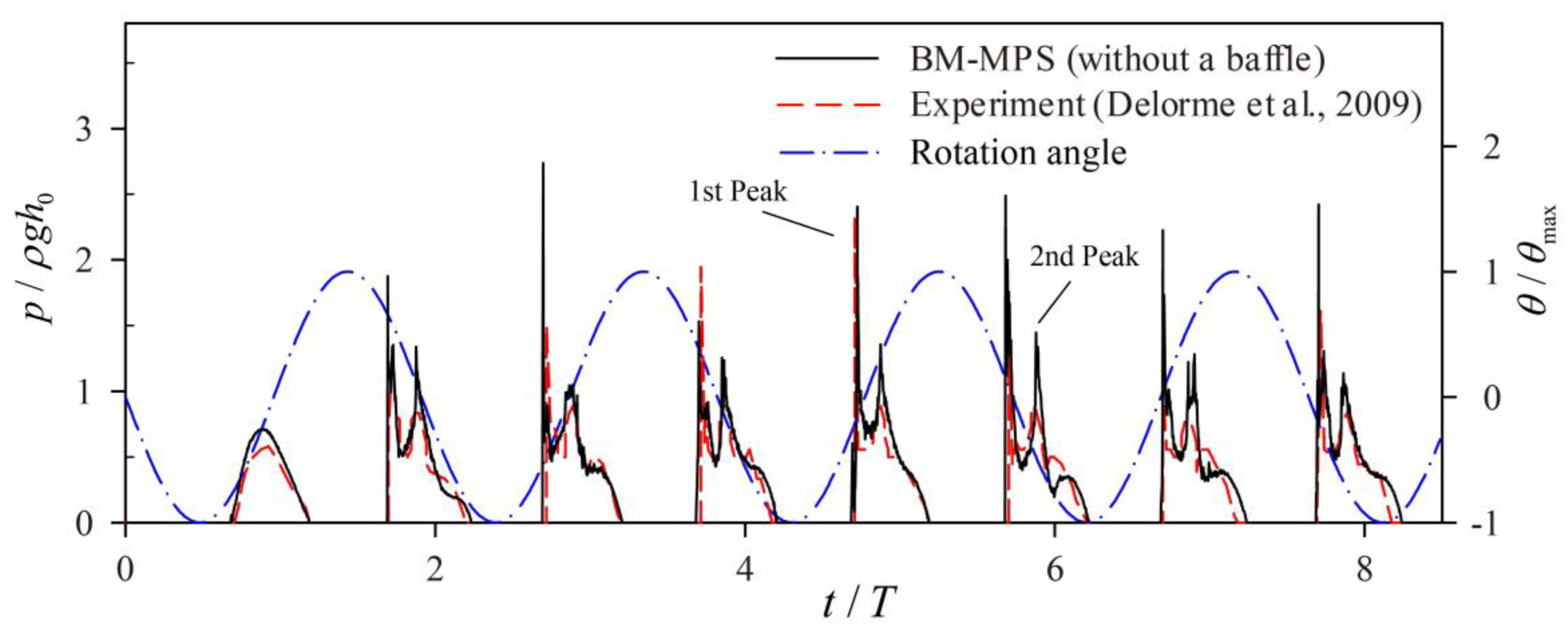
For shallow liquid sloshing, the maximum impact pressure on the border commonly occurs near the free surface. To check the calculation precision of impact pressure, the time history of impact pressure calculated at point A without a baffle is plotted in Figure 6. The experimental result represented by the red dash line is given to verify the numerical result. In addition, the time history of rotational angle of the tank under the excitation is given as well. Overall, the calculated impact pressure by the BM-MPS method coincides with the experimental one very well. Figure 6 reveals that the impact pressure curve has a double-peak phenomenon when there is not any sloshing-suppressing device. The first peak corresponds to the maximum pressure during each excitation period, whose magnitude is generally much larger than that of the second peak. Owing to its importance, the maximum pressure peaks in Figure 6 are extracted and analyzed. The mean values of the dimensionless maximum pressure and the standard deviations are listed in Table 1. The mean value of the numerical result is larger than that of the experiment, but is quite close to the experimental maximum value. In addition, the standard deviation of the numerical value is much smaller. To capture the pressure peak, the frequency of impact pressure calculation is set as 1666 Hz, which is higher than the cut-off frequency of the experimental data (400 Hz) [22]. Hence, the discrepancy between the numerical and experimental results is acceptable. Through the verification of the above results, it can be proved that BM-MPS is an appropriate numerical method for studying liquid sloshing.
To investigate the damping effect and mechanism of vertical baffles, a series of sloshing tests are conducted by the BM-MPS method, whose specific information is listed in Table A1 in Appendix A. The parameters of baffle configuration (HB, HS) and the excitation frequency are the major impact factors. To facilitate the analysis, the statistics of calculated impact pressure at point A for each test are shown in the table, including the maximum and mean values of non-dimensional peak pressure (Pmax/ρgh0) and significant pressure (P1/3/ρgh0). Here, P1/3 denotes the average value of the top third data as the pressure values are arranged from highest to lowest during each excitation period, and is defined as significant pressure. Considering the irregularity due to the onset of movement, the data statistics and analyses are started from the third period.

3.3. The Effect of Baffle Height on Restraining Sloshing

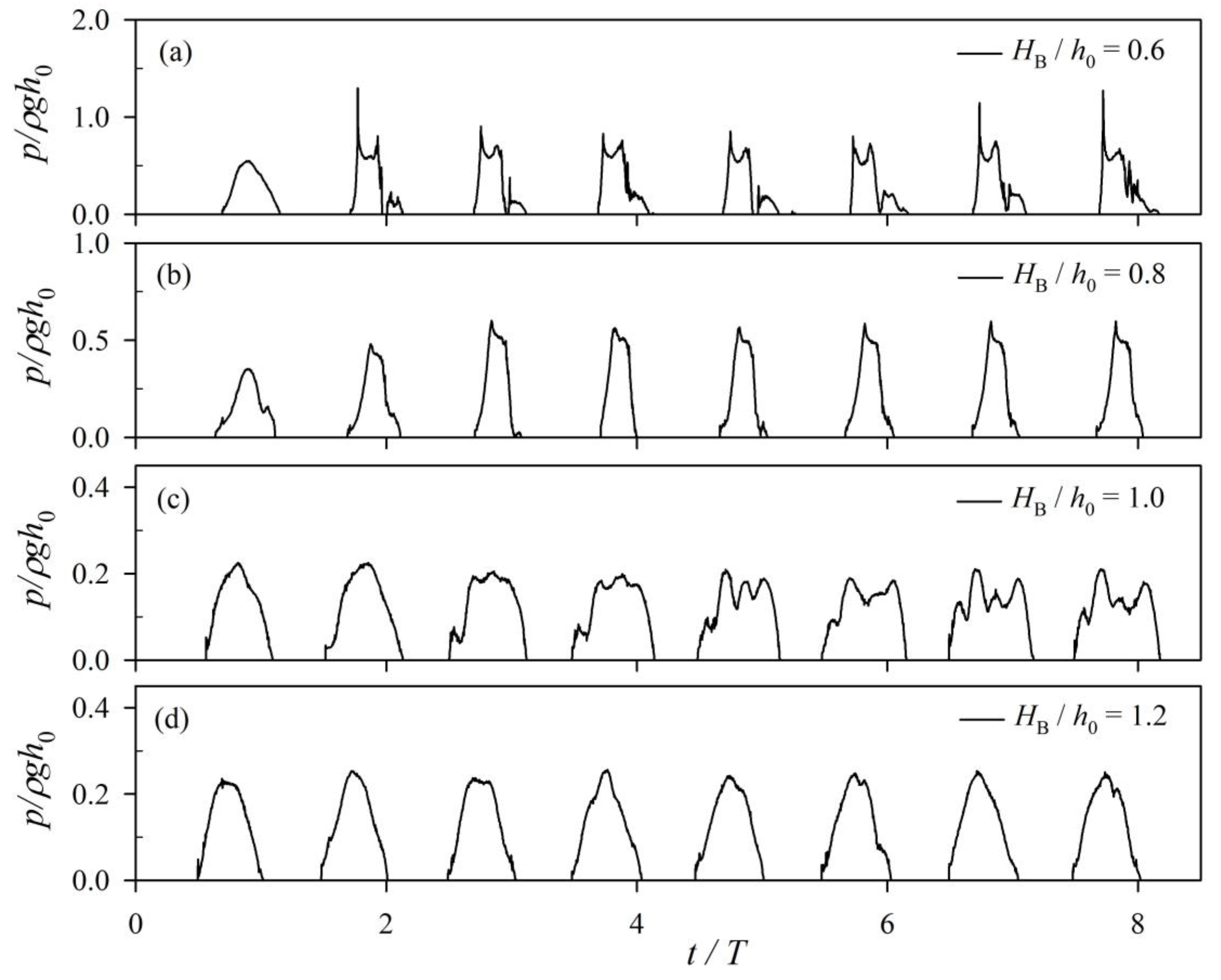
Figure 7 shows the time histories of impact pressure at point A under the action of different baffles heights. The excitation period is still 1.91 s, and the baffles are all bottom-mounted. As shown in Figure 7a, the pressure curve remains the double-peak pattern when the height of the baffle is 0.6h0, but the magnitude of the peaks decreases obviously, especially for the first peak. When the baffle height is up to 0.8h0, the pressure curve changes to a single-peak pattern, and both the value and duration of the impact pressure diminishes. As the height increases continuously, the pressure value keeps decreasing and the phenomenon of the instantaneous pressure spike evaporates. This means the action of water slamming is prevented and the dynamic pressure at point A arises from the rise in the water level. Compared with the time history of impact pressure in Figure 7d, the irregular curve in Figure 7c indicates that the free surface has a relatively remarkable fluctuation phenomenon when the baffle is flush with the free surface.
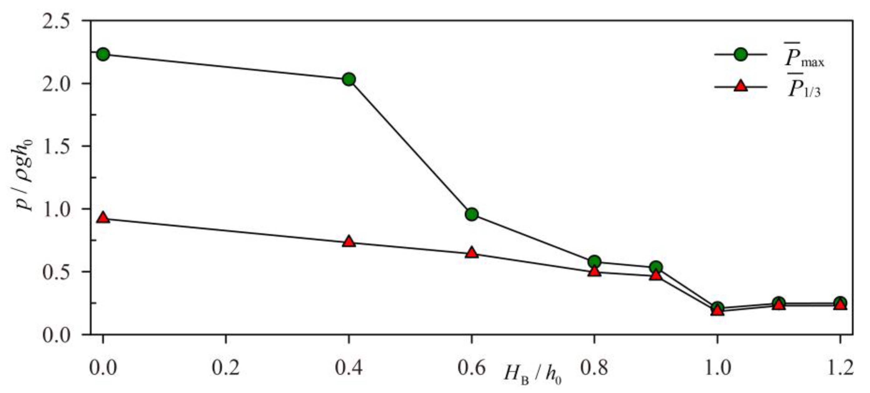
In order to clarify the relationship between the impact pressure and the baffle height, the variation trends of the mean maximum pressure P ¯ max , the mean significant pressure P ¯ 1 / 3 with the baffle height HB are described in Figure 8. The value of P ¯ 1 / 3 tends to reflect the maximum surface elevation. The result is that the damping effect of the baffle is minuscule when its height is less than 0.4h0. When the height is up to 1.1h0, the maximum impact pressure does not decrease any more. As the baffle height increases from 0.4h0 to 1.1h0, P ¯ max  rapidly decreases and approaches P ¯ 1 / 3 . The diminution of impact pressure means the effectiveness of baffle restraining sloshing increases with the increase of baffle height. The best sloshing-suppressing condition is when the baffle is flush with the free surface.
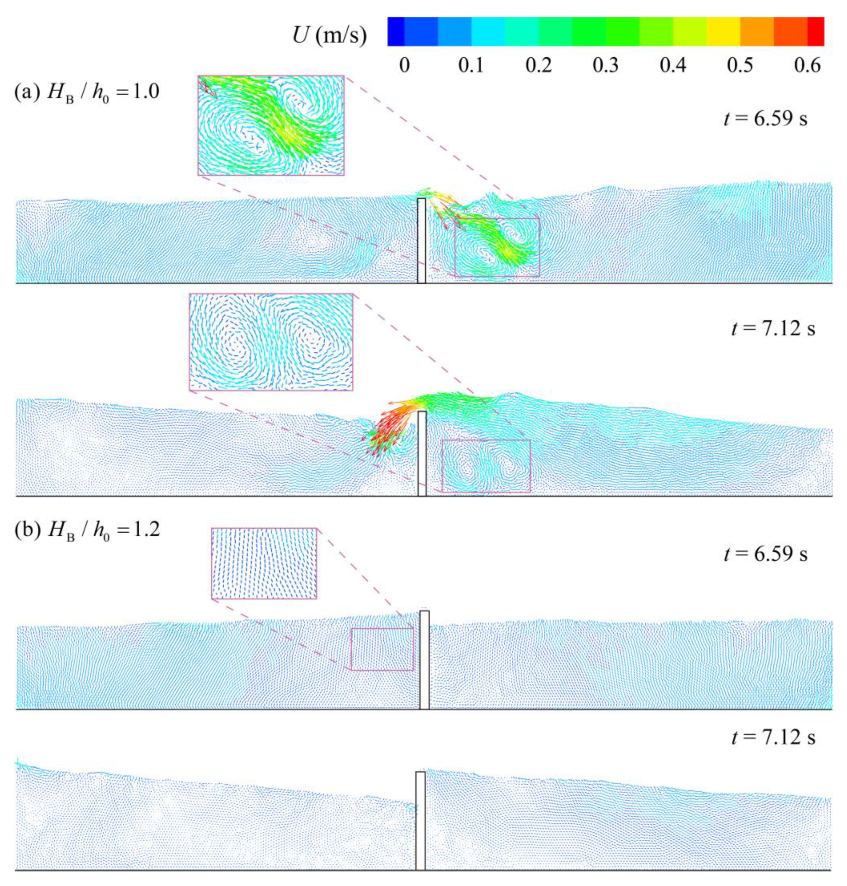
Figure 9 shows the velocity field distributions when the baffle height is 1.0h0 and 1.2h0. When the baffle height is 1.2h0, water is separated as two parts and vortices barely appear (Figure 9b). While the baffle is flush with the surface, vortices are formed since water overtopping is partly allowed over the baffle top (Figure 9a), and both vortex damping and hydrodynamic damping play a role in this state.

3.4. The Effect of Baffle Height on Resonance

As is well-known, when the excitation frequency is close to the resonance frequency of the liquid tank, the impact pressure is commonly the most intense. Previous studies have revealed that the resonance frequency of the unbaffled tank is around its natural frequency [3]. In this section, the effect of baffle height on the resonance characteristics of sloshing forced by a rotational excitation is discussed in detail.
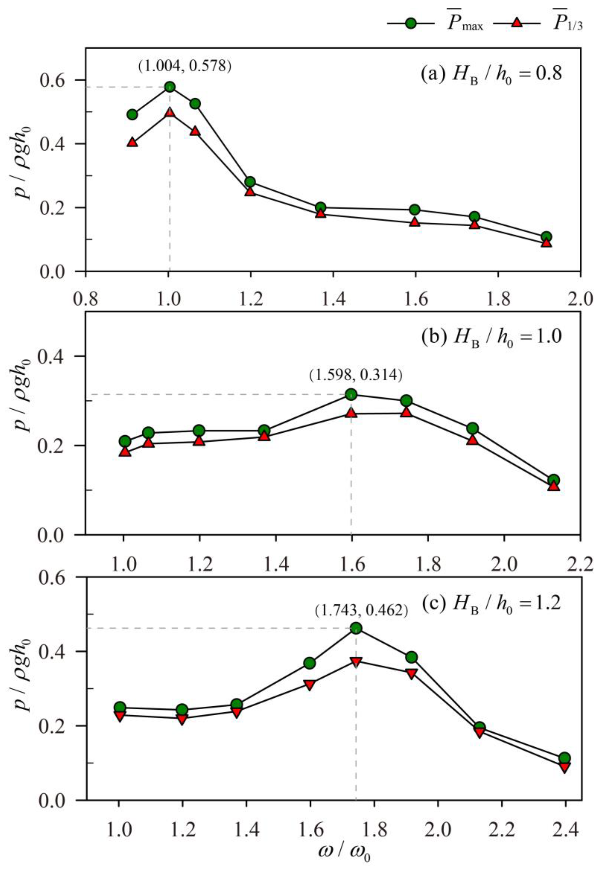
The variation trends of P ¯ max and P ¯ 1 / 3 for the bottom-mounted baffles under different excitation frequencies are presented in Figure 10. The baffle heights are 0.8h0, 1.0h0, and 1.2h0, corresponding to the three types (a, c, e) in Figure 2, respectively. For HB/h0 = 0.8, the maximum impact pressure still occurs around the natural frequency (ω/ω0 = 1.004). The presence of the vertical baffle does not change the resonance characteristics of sloshing. However, a different consequence results when HB/h0 >= 1. According to Figure 10b,c, the excitation frequency corresponding to the maximum P ¯ max is around 1.598ω0 for HB = 1.0h0, and is 1.743ω0 for HB = 1.2h0, which means the resonance frequency increases.

3.5. The Damping Effect of Wall-Mounted Baffles

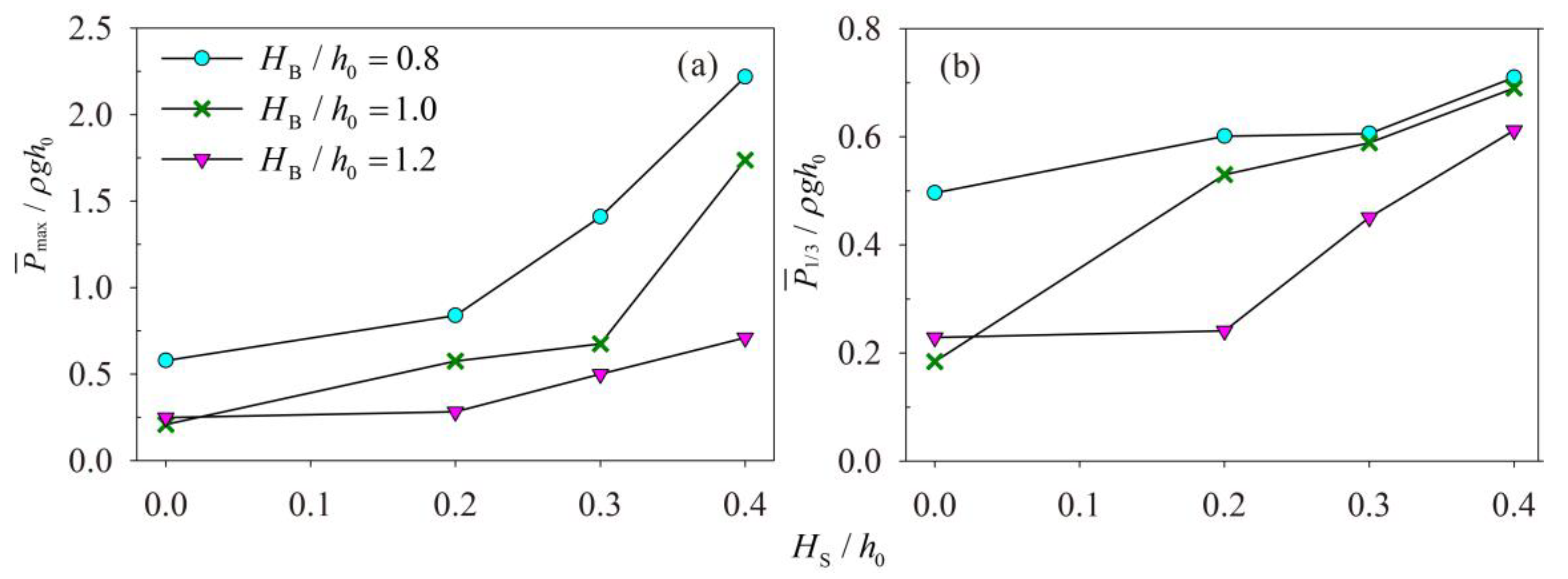
Figure 11 shows the statistical result of impact pressure for cases where the baffles are not mounted at the bottom and there is a certain space for fluid flow-through in the lower part of the tank. Three scales of gap are investigated (HS/h0 = 0.2, 0.3 and 0.4, respectively), and the effect of baffle top elevation are considered as well (HB/h0 = 0.8, 1.0 and 1.2, respectively). The result reveals that both P ¯ max and P ¯ 1 / 3 gradually get larger with the increase of HS/h0 no matter whether the baffle is immersed or emerged.
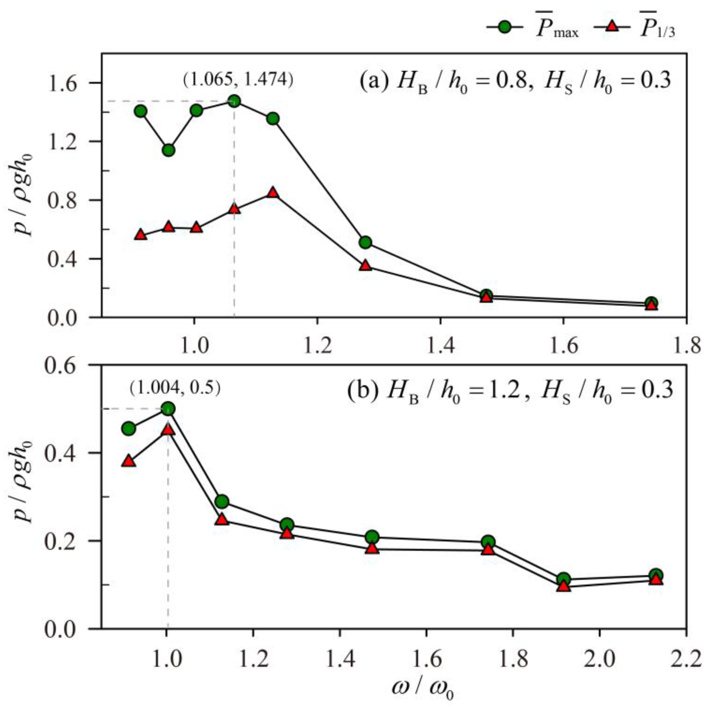
As for the baffles where HS/h0 = 0.3 and HB/h0 = 0.8, 1.2, the variation of the impact pressure under different excitation frequencies are shown in Figure 12. For HB/h0 = 0.8, P ¯ max is maximum as the excitation frequency is 1.065ω0 while P ¯ 1 / 3 is maximum at ω/ω0 = 1.128. Compared with Figure 10a, the resonance frequency just has a little change, and the values of P ¯ max are adjacent when ω/ω0 = 1.128, 1.065, 1.004 and 0.913. However, Figure 12b shows the effect of baffle on resonance characteristics has changed in essence when HB/h0 = 1.2 and HS/h0 = 0.3. Completely different from Figure 10c, the maximum value of P ¯ max remains around the natural frequency (ω/ω0 = 1.004).

4. Discussion

As for a bottom-mounted vertical baffle, the effectiveness of suppressing impact pressure is negligible when the baffle height is 0.4h0 (Figure 8). However, for the same height scale, the vertical baffle acts on suppressing sloshing in a tank forced by a lateral motion. Associating with Figure 7, the effect of the vertical baffle reducing impact pressure is satisfactory when its height is up to 0.8h0. Hence, the demand on the baffle height under rotational excitation is higher than that under horizontal excitation.
The variation trends of resonance frequency for different baffle heights in Figure 10 is consistent with the phenomenon reflected from the sloshing noise investigation by Golla and Venkatesham [1]. The result indicates that at least when the baffle top reaches the free surface, the baffle has the function of changing the scale of the tank, and then alters resonance characteristics. According to the natural frequency calculation formula (Equation (18)), if the length of the tank is only 0.45 m, the natural frequency will become 6.254 s−1 (≈ 1.91ω0). As shown in Figure 10c, the resonance frequency when the baffle height is 1.2h0 is close to this value. That means that when the tank is separated into independent chambers by baffles, the resonance frequency is close to the natural frequency of the individual chamber. As for the magnitude of impact pressure, the values around resonance frequency for HB/h0 >= 1 are less than that when the baffle height is 0.8h0, but larger than the values when the excitation frequency is about ω0.
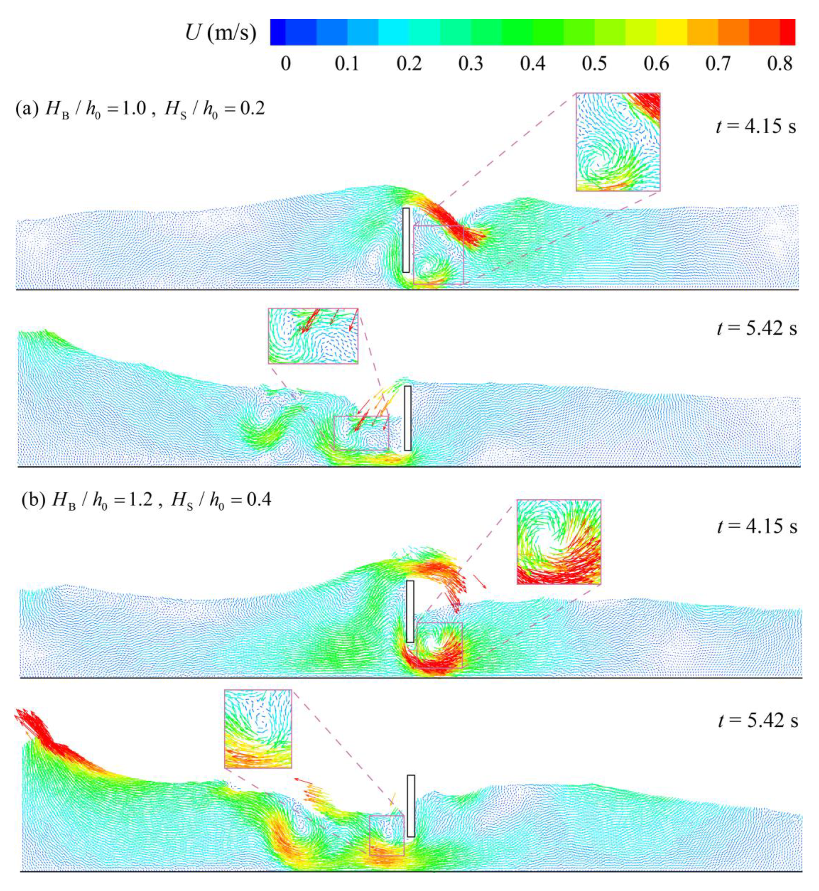
To further understand the damping mechanism of wall-mounted baffles, Figure 13 gives the velocity field distributions when HB/h0 is 1.0 and HS/h0 is 0.2, as well as when HB/h0 is 1.2 and HS/h0 is 0.4. As shown in the figure, fluid flows along the baffle and forms a jet stream at the gap. Some vortices are generated around the baffle bottom. Compared with the velocity fields in Figure 9a, the number of vortices in Figure 13a goes up. Figure 13b shows that more water goes through the underside of the baffle as the lower free space is expanded. With the increase of lower free space, the restriction of the baffle to water motion is alleviated, which means the hydrodynamic damping effect of baffle blocking water weakens. In addition, some data extracted from Table A1 are listed in Table 2. For the same height, when there is a small gap between the baffle and the bottom, the damping effect of wall-mounted baffles is approximate to that of a bottom-mounted baffle, but the effectiveness of baffle suppressing sloshing decreases with the expansion of the gap. As for the wall-mounted vertical baffle, the turbulent energy dissipation caused by the vortices from the bottom edge of the baffle is not enough to compensate for the loss of blockage effect when the gap is large.

5. Conclusions

In this study, the BM-MPS method, an improved MPS method, is suggested for the investigation of shallow liquid sloshing in a baffled rectangular tank under a rotational motion with a large excitation amplitude. The influence of configurations of vertical baffles on the associated damping effect and mechanism is examined in detail through a series of tests.
First, the precise calculation of pressure demonstrates that the present numerical method is an effective way to study the effect of vertical baffles on suppressing impact pressure, and the delicate velocity field contributes to make the damping mechanism of baffles clear.
Bottom-mounted vertical baffles have similar damping effects under rotational excitation to those under horizontal excitation, but require a much higher baffle height, which should be up to 0.6h0 to achieve acceptable sloshing suppression. The optimum height appears when the baffle top is flush with the free surface. As for wall-mounted baffles, the effectiveness of restraining sloshing decreases with the increase of the lower free space (HS). In addition, when the baffle height is equal to, or larger than the static water depth, the resonance frequency of liquid sloshing is altered.
As for the damping mechanism, it is dependent on the configurations of vertical baffles. For the immersed bottom-mounted baffle and the wall-mounted baffle, the damping effect is achieved by hydrodynamic damping and vortex damping. The setting of a gap between the baffle and the tank bottom can enhance vortex damping somewhat but will weaken hydrodynamic damping. For the surface-piercing bottom-mounted baffle, one of the reasons that sloshing is restrained is the hydrodynamic damping, and another is that the tank is resized. When the baffle is flush with the surface, the three damping mechanisms work together and the damping effect is optimal.

Author Contributions

Conceptualization, L.W. and M.X.; methodology, L.W.; validation, L.W.; writing and editing, L.W. and Q.Z.; funding acquisition, M.X. All authors have read and agreed to the published version of the manuscript.

Funding

This research was funded by Natural Science Foundation of Jiangsu Province (BK20200729), Universities Natural Science Research Project of Jiangsu Province (20KJB170027), and Natural Resources Development Special Project of Jiangsu Province (JSZRHYKJ202002).

Institutional Review Board Statement

Not applicable.

Informed Consent Statement

Not applicable.

Data Availability Statement

Not applicable.

Conflicts of Interest

The authors declare no conflict of interest.

Appendix A

Table A1. Calculation conditions and pressure statistics of all tests.
HB/h0HS/h0T (s)ω/ω0Pmax/ρgh0P1/3/ρgh0
MaximumMeanMaximumMean
001.911.0042.7362.2310.9810.921
0.401.911.0042.4672.0320.7790.732
0.601.911.0041.2980.9550.6680.643
0.801.911.0040.6020.5780.5320.496
0.21.110.8390.6660.601
0.31.5941.410.6670.606
0.42.6612.2180.7490.71
02.10.9130.5670.4910.4970.402
1.81.0650.5610.5250.4670.437
1.61.1980.3330.280.2880.247
1.41.3690.2280.20.1980.179
1.21.5980.2130.1930.1670.152
1.11.7430.1850.1710.1530.144
11.9170.1280.1080.0990.087
0.32.10.9131.7211.4060.590.557
20.9591.2861.1390.650.611
1.81.0652.5281.4740.7710.735
1.71.1282.5351.3550.8690.844
1.51.2780.6310.510.5190.347
1.31.4750.2120.1480.1570.13
1.11.7430.1770.0960.1460.077
0.901.911.0040.5760.5330.5060.465
101.911.0040.2160.2090.1930.184
0.20.6170.5750.5520.53
0.30.750.6760.6010.589
0.42.5451.7370.7080.69
01.81.0650.2460.2280.2150.204
1.61.1980.240.2330.2160.208
1.41.3690.240.2330.220.219
1.21.5980.3420.3140.2850.271
1.11.7430.3180.30.2770.272
11.9170.2630.2380.2250.21
0.92.130.1550.1220.1350.107
1.101.911.0040.260.2480.2380.229
1.201.911.0040.2570.2490.2360.229
0.20.3070.2830.2670.241
0.30.5140.50.4620.451
0.40.7920.7110.6530.612
01.61.1980.270.2430.2440.22
1.41.3690.2780.2570.2450.239
1.21.5980.4020.3680.3250.313
1.11.7430.5310.4620.3930.374
11.9170.5460.3840.3610.343
0.92.130.2220.1950.2060.185
0.82.3960.1650.1130.1420.091
0.32.10.9130.4620.4550.4080.379
1.71.1280.330.2890.2520.246
1.51.2780.2790.2360.2330.215
1.31.4750.2840.2080.2490.181
1.11.7430.2080.1970.1890.178
11.9170.1220.1120.0980.095
0.92.130.1310.1210.1140.11
Note: Pmax denotes the maximum value of calculated impact pressure during each excitation period; P1/3 denotes the average value of the top third data as the pressure values are arranged from highest to lowest during each excitation period.

References

  1. Golla, S.T.; Venkatesham, B. Experimental study on the effect of centrally positioned vertical baffles on sloshing noise in a rectangular tank. Appl. Acoust. 2021, 176, 107890. [Google Scholar] [CrossRef]
  2. Yu, L.; Xue, M.; Zhu, A. Numerical Investigation of Sloshing in Rectangular Tank with Permeable Baffle. J. Mar. Sci. Eng. 2020, 8, 671. [Google Scholar] [CrossRef]
  3. Xue, M.; Zheng, J.; Lin, P.; Yuan, X. Experimental study on vertical baffles of different configurations in suppressing sloshing pressure. Ocean. Eng. 2017, 136, 178–189. [Google Scholar] [CrossRef]
  4. Nayak, S.K.; Biswal, K.C. Fluid damping in rectangular tank fitted with various internal objects—An experimental investigation. Ocean. Eng. 2015, 108, 552–562. [Google Scholar] [CrossRef]
  5. Liu, D.; Lin, P. Three-dimensional liquid sloshing in a tank with baffles. Ocean. Eng. 2009, 36, 202–212. [Google Scholar] [CrossRef]
  6. Akyildız, H.; Erdem Ünal, N. Sloshing in a three-dimensional rectangular tank: Numerical simulation and experimental validation. Ocean. Eng. 2006, 33, 2135–2149. [Google Scholar] [CrossRef]
  7. Celebi, M.S.; Akyildiz, H. Nonlinear modeling of liquid sloshing in a moving rectangular tank. Ocean. Eng. 2002, 29, 1527–1553. [Google Scholar] [CrossRef]
  8. Younes, M.F.; Younes, Y.K.; El-Madah, M.; Ibrahim, I.M.; El-Dannanh, E.H. An experimental investigation of hydrodynamic damping due to vertical baffle arrangements in a rectangular tank. Proc. Inst. Mech. Eng. Part. M J. Eng. Marit. Environ. 2007, 221, 115–123. [Google Scholar] [CrossRef]
  9. Faltinsen, O.M.; Timokha, A.N. Sloshing; Cambridge University Press: New York, NY, USA, 2009. [Google Scholar]
  10. Panigrahy, P.K.; Saha, U.K.; Maity, D. Experimental studies on sloshing behavior due to horizontal movement of liquids in baffled tanks. Ocean. Eng. 2009, 36, 213–222. [Google Scholar] [CrossRef]
  11. Jung, J.H.; Yoon, H.S.; Lee, C.Y.; Shin, S.C. Effect of the vertical baffle height on the liquid sloshing in a three-dimensional rectangular tank. Ocean. Eng. 2012, 44, 79–89. [Google Scholar] [CrossRef]
  12. Poguluri, S.K.; Cho, I.H. Liquid sloshing in a rectangular tank with vertical slotted porous screen: Based on analytical, numerical, and experimental approach. Ocean. Eng. 2019, 189, 106373. [Google Scholar] [CrossRef]
  13. Yu, L.; Xue, M.; Jiang, Z. Experimental investigation of parametric sloshing in a tank with vertical baffles. Ocean. Eng. 2020, 213, 107783. [Google Scholar] [CrossRef]
  14. Tang, Y.; Liu, Y.; Chen, C.; Chen, Z.; He, Y.; Zheng, M. Numerical study of liquid sloshing in 3D LNG tanks with unequal baffle height allocation schemes. Ocean. Eng. 2021, 234, 109181. [Google Scholar] [CrossRef]
  15. Kamath, A.; Grotle, E.L.; Bihs, H. Numerical Investigation of Sloshing Under Roll Excitation at Shallow Liquid Depths and the Effect of Baffles. J. Mar. Sci. Appl. 2021, 20, 185–200. [Google Scholar] [CrossRef]
  16. Monaghan, J.J. Smoothed particle hydrodynamics. Annu. Rev. Astron Astr. 1992, 30, 543–573. [Google Scholar] [CrossRef]
  17. Koshizuka, S.; Oka, Y. Moving-particle semi-implicit method for fragmentation of incompressible fluid. Nucl. Sci. Eng. 1996, 123, 421–434. [Google Scholar] [CrossRef]
  18. Shimizu, Y.; Gotoh, H.; Khayyer, A. An MPS-based particle method for simulation of multiphase flows characterized by high density ratios by incorporation of space potential particle concept. Comput. Math. Appl. 2018, 76, 1108–1129. [Google Scholar] [CrossRef]
  19. Hermange, C.; Oger, G.; Le Chenadec, Y.; Le Touze, D. A 3D SPH-FE coupling for FSI problems and its application to tire hydroplaning simulations on rough ground. Comput. Method Appl. M 2019, 355, 558–590. [Google Scholar] [CrossRef]
  20. Zhang, Y.; Wan, D.; Hino, T. Comparative study of MPS method and level-set method for sloshing flows. J. Hydrodyn. Ser. B 2014, 26, 577–585. [Google Scholar] [CrossRef]
  21. Gotoh, H.; Khayyer, A.; Ikari, H.; Arikawa, T.; Shimosako, K. On enhancement of Incompressible SPH method for simulation of violent sloshing flows. Appl. Ocean. Res. 2014, 46, 104–115. [Google Scholar] [CrossRef]
  22. Delorme, L.; Colagrossi, A.; Souto-Iglesias, A.; Zamora-Rodríguez, R.; Botía-Vera, E. A set of canonical problems in sloshing, Part I: Pressure field in forced roll—comparison between experimental results and SPH. Ocean. Eng. 2009, 36, 168–178. [Google Scholar] [CrossRef]
  23. Zheng, X.; You, Y.; Ma, Q.; Khayyer, A.; Shao, S. A Comparative Study on Violent Sloshing with Complex Baffles Using the ISPH Method. Appl. Sci. 2018, 8, 904. [Google Scholar] [CrossRef] [Green Version]
  24. Khayyer, A.; Tsuruta, N.; Shimizu, Y.; Gotoh, H. Multi-resolution MPS for incompressible fluid-elastic structure interactions in ocean engineering. Appl. Ocean. Res. 2019, 82, 397–414. [Google Scholar] [CrossRef]
  25. Zhang, G.; Wu, J.; Sun, Z.; Moctar, O.E.; Zong, Z. Numerically simulated flooding of a freely-floating two-dimensional damaged ship section using an improved MPS method. Appl. Ocean. Res. 2020, 101, 102207. [Google Scholar] [CrossRef]
  26. Khayyer, A.; Gotoh, H. Modified Moving Particle Semi-implicit methods for the prediction of 2D wave impact pressure. Coast. Eng. 2009, 56, 419–440. [Google Scholar] [CrossRef]
  27. Wang, L.; Khayyer, A.; Gotoh, H.; Jiang, Q.; Zhang, C. Enhancement of pressure calculation in projection-based particle methods by incorporation of background mesh scheme. Appl. Ocean. Res. 2019, 86, 320–339. [Google Scholar] [CrossRef]
  28. Wang, L.; Jiang, Q.; Zhang, C. Improvement of moving particle semi-implicit method for simulation of progressive water waves. Int. J. Numer. Meth. Fl. 2017, 85, 69–89. [Google Scholar] [CrossRef]
  29. Koshizuka, S.; Nobe, A.; Oka, Y. Numerical analysis of breaking waves using the moving particle semi-implicit method. Int. J. Numer. Meth. Fl. 1998, 26, 751–769. [Google Scholar] [CrossRef]
  30. Wang, L.; Jiang, Q.; Zhang, C. Numerical simulation of solitary waves overtopping on a sloping sea dike using a particle method. Wave Motion. 2020, 95, 102535. [Google Scholar] [CrossRef]
  31. Faltinsen, O.M. A numerical nonlinear method of sloshing in tanks with two-dimensional flow. J. Ship Res. 1978, 22, 193–202. [Google Scholar] [CrossRef]
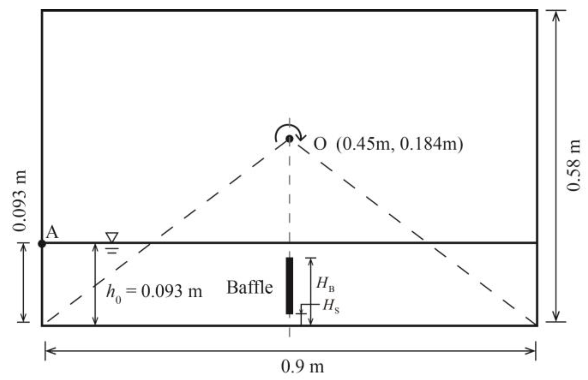
Figure 1. Initial conditions for liquid sloshing simulation under a rotational excitation.
Jmse 09 01110 g001
Figure 2. Various vertical baffles configurations.
Jmse 09 01110 g002
Figure 3. Snapshots of sloshing flow with pressure field under the excitation period T = 1.91 s. (a) t = 2.04 s; (b) t = 2.54 s; (c) t = 3.09 s; (d) t = 3.38 s. (Left: without a baffle; Right: with a vertical baffle HB/h0 = 0.8; The dash lines are the free surfaces extracted from the experimental images. The image data are available at http://canal.etsin.upm.es/ftp/SPHERIC_BENCHMARKS/case_2/index.html, accessed on 25 September 2021. As for the experiment information, please refer to reference [22]).
Jmse 09 01110 g003aJmse 09 01110 g003b
Figure 4. Velocity fields during liquid sloshing without a baffle. (a) t = 3.09 s; (b) t = 3.38 s.
Jmse 09 01110 g004
Figure 5. Velocity fields during liquid sloshing with a vertical baffle HB/h0 = 0.8. (a) t = 3.09 s; (b) t = 3.38 s.
Jmse 09 01110 g005
Figure 6. Time histories of impact pressure at point A without a baffle (T = 1.91 s, ω/ω0 = 1.004).
Jmse 09 01110 g006
Figure 7. Time histories of impact pressure at point A with different baffle heights (T = 1.91 s, ω/ω0 = 1.004). (a) HB/h0 = 0.6; (b) HB/h0 = 0.8; (c) HB/h0 = 1.0; (d) HB/h0 = 1.2.
Jmse 09 01110 g007
Figure 8. Mean values of maximum pressure and significant pressure at point A with different height baffles (T = 1.91 s, ω/ω0 = 1.004).
Jmse 09 01110 g008
Figure 9. Distributions of velocity fields with baffles at two moments (T = 1.91 s, ω/ω0 = 1.004). (a) HB/h0 = 1.0; (b) HB/h0 = 1.2.
Jmse 09 01110 g009
Figure 10. Variation trends of P ¯ max and P ¯ 1 / 3 for the three types of bottom-mounted baffles under different excitation frequencies. (a) HB/h0 = 0.8; (b) HB/h0 = 1.0; (c) HB/h0 = 1.2.
Jmse 09 01110 g010
Figure 11. Variation trends of impact pressure with different gap sizes (T = 1.91 s, ω/ω0 = 1.004). (a) P ¯ max ; (b) P ¯ 1 / 3 .
Jmse 09 01110 g011
Figure 12. Variation trends of impact pressure of two kinds of wall-mounted baffles under different excitation frequencies. (a) HB/h0 = 0.8, HS/h0 = 0.3; (b) HB/h0 = 1.2, HS/h0 = 0.3.
Jmse 09 01110 g012
Figure 13. Distributions of velocity fields when the bottom of the baffle is suspended (T = 1.91 s, ω/ω0 = 1.004). (a) HB/h0 = 1.0, HS/h0 = 0.2; (b) HB/h0 = 1.2, HS/h0 = 0.4.
Jmse 09 01110 g013
Table 1. Statistics on the dimensionless maximum pressure.
BM-MPSExperiment
Maximum peak value2.742.33
Mean value2.231.71
Standard deviation0.3780.593
Table 2. The comparison of impact pressure for baffles with same height but different configuration (T = 1.91 s, ω/ω0 = 1.004).
ConfigurationsBaffle Height P ¯ max / ρ g h 0 P ¯ 1 / 3 / ρ g h 0
HB/h0 = 0.6, HS/h0 = 0.00.6h00.9550.643
HB/h0 = 0.8, HS/h0 = 0.20.8390.601
HB/h0 = 1.0, HS/h0 = 0.41.7370.69
HB/h0 = 0.8, HS/h0 = 0.00.8h00.5780.496
HB/h0 = 1.0, HS/h0 = 0.20.5750.53
HB/h0 = 1.2, HS/h0 = 0.40.7110.612
HB/h0 = 1.0, HS/h0 = 0.01.0h00.2090.184
HB/h0 = 1.2, HS/h0 = 0.20.2830.241
Publisher’s Note: MDPI stays neutral with regard to jurisdictional claims in published maps and institutional affiliations.