Article

Dynamics Simulation of Grasping Process of Underwater Vehicle-Manipulator System

1
College of Engineering, Ocean University of China, Qingdao 266100, China
2
Key Laboratory of Ocean Engineering of Shandong Province, Qingdao 266100, China
*
Author to whom correspondence should be addressed.
J. Mar. Sci. Eng. 2021, 9(10), 1131; https://doi.org/10.3390/jmse9101131
Submission received: 19 September 2021 / Revised: 9 October 2021 / Accepted: 12 October 2021 / Published: 15 October 2021
(This article belongs to the Section Ocean Engineering)

Abstract

:
Underwater vehicle-manipulator system (UVMS) can be applied to fulfill different complex underwater tasks such as grasping, drilling, sampling, etc. It is widely used in the field of oceanographic research, marine exploration, military, and commercial applications. In this paper, the dynamic simulation of UVMS is presented in the process of grasping an object. First, the dynamic model of UVMS, which considers the change of the load of manipulator when the end effector of manipulator grasps the object, is developed. To compare different conditions, numerical simulation of grasping processes without/with vehicle attitude control are carried out. The simulation results show that the coupling dynamics between the vehicle and the manipulator in the grasping process are clearly illustrated. It deteriorates the positioning accuracy of the end effector of the manipulator and is harmful to underwater precision operations. The tracking position error of end effector without vehicle control is large and UVMS cannot complete the grasping task under this condition. Vehicle control can compensate the motion of the vehicle due to the coupling effect caused by the motion of the manipulator. This study will contribute to underwater operation mission for UVMS with floating base.

1. Introduction

Underwater vehicle-manipulator system (UVMS) is a powerful tool for ocean exploration and marine environment observation [1,2,3]. It can also be applied to fulfill the different complex underwater operation tasks such as grasping, drilling, sampling, etc., [4,5,6]. Due to the unknown underwater environment caused by poor knowledge of the hydrodynamic coefficients, the floating base and under-actuated of the UVMS, strongly nonlinear and coupled dynamics, and unpredictable external disturbances, these bring huge challenge for the underwater operation mission. Therefore, motion coordination and disturbance compensation for UVMS need to be considered to reduce the coupling effect between the vehicle and the manipulator [7,8,9,10]. Underwater grasping operation of UVMS is also a significant point in research and engineering practice.
Plenty of kinds of UVMSs have been studied and developed in recent years. ALIVE robot (see Figure 1a) equipped with two hydraulic grasps for autonomous underwater docking and a 7 degree-of-freedoms (DOF) hydraulic manipulator used for valve turning task [11]. SAUVIM (see Figure 1b), a semi-autonomous UVMS equipped with an Ansaldo 7 DOF manipulator developed in the AMADEUS project [12], was proposed for free floating underwater operation [13]. In RAUVI, TRIDENT, and TRITON project, GIRONA 500 (see Figure 1c) is a lighter I-AUV of less than 200 kg, whose mass is lighter than ALIVE (3.5 ton) and SAUVIM (6 ton) [14]. Therefore, the effects of the mass and geometry of vehicle and manipulator on dynamic coupling condition should be considered [15,16]. A lightweight multi-link symmetrical structure was carried out and designed to reduce the coupling effect on the vehicle caused by the motion of manipulator [17]. Meanwhile, dual arm UVMS was proposed and developed for cooperating manipulation in recent years [18]. Some UVMS with dual arms have been studied, such as DexROV (see Figure 1d) [19], Ocean One (see Figure 1e) [20], Aquanaut [21], etc. Dual arms can balance the operation in both sides and improve the stability of UVMS.
Underwater grasping is an important function for underwater operation. A UVMS requires coordinated motion and more robust and optimal control scheme to overcome some adverse factors. Sarkar and Podder [24] proposed a motion coordination planning strategy based on the optimized hydrodynamic drag force. Considering the redundancy of UVMS, Antonelli and Chiaverini [25] adopted a fuzzy task-priority inverse kinematics resolution approach to manage the vehicle-manipulator coordination. Han et al. [26] proposed a performance index for redundancy resolution of a UVMS, the restoring moments of the UVMS during manipulation could be reduced by optimizing the index. In order to maintain dynamic stability of the UVMS, zero moment point method is adopted in reference [27]. Considering manipulator joint limit, weighted minimum norm method can be applied in motion planning of UVMS [28]. Considering the collision avoidance, a local motion planning method for inspection mission had been presented and a trained artificial neural network was utilized [29]. According to sampling-based, search-based, and optimization-based motion planners, these algorithms and their performance with different metrics were analyzed and compared by qualitative/quantitative [30].
The body of UVMS has three working modes: under-actuated, fully actuated, and over-actuated [5,31,32]. It is obvious that fully actuated and over-actuated mode can ensure the vehicle station keeping and dynamic positioning. However, under-actuated mode can reduce costs and energy consumption. An indirect adaptive control method of UVMS for underwater manipulation tasks (pick and place operation) based on an extended Kalman filter was presented by Mohan and Kim. This method overcomes the disadvantages of direct adaptive control scheme and existing disturbance observers [33]. Then they carried out a coordinated motion control scheme using disturbance observer in task space [34]. Whereas a tracking controller with both joint-space and task-space tracking errors was proposed by Han et al. [35]. Barbalata et al. [36] utilized force/motion controllers to handle a lightweight UVMS interaction with the underwater environment and compensate the coupling effects between the vehicle and the manipulator. Huang et al. [37] investigated the state-of-the-art about dexterous operation underwater robot, underwater autonomous environmental perception, UVMS modeling and coordinated control, target grasping, etc. Acceleration-level task priority redundancy resolution method was proposed and remotely autonomous underwater with organism absorb or grasp function were analyzed and compared. Conti et al. [38] proposed a control architecture for intervention UVMS and studied on a suitable grasp planning strategy. Anderlini et al. [39] investigated an ROV with the consequent changes system dynamics when carried an object, an adaptive model predictive control scheme was proposed and its performance was compared with PID and sliding mode control. Many different control strategies for UVMS to track task trajectories were designed and carried out in recent years. Because UVMS consists of two subsystems, vehicle station-keeping and manipulator motion control are also important. There are many different control methods, such as PID control [40], model-based motion control [9,41], adaptive backstepping control [42,43,44,45], model predictive control [46,47,48,49,50,51,52], adaptive control [53,54], active disturbance rejection control [55,56], force/position control [36,57], dynamic surface control [58,59], and so on. In addition, sliding mode control of UVMS for second-order system is common and reliable, such as sliding mode impedance control [60], terminal sliding control [43,53,61,62,63,64], dynamic sliding mode control [65], robust sliding mode control [5], multiple sliding mode methods [66], dynamic neural network [67], double-loop sliding mode control [68,69,70], adaptive sliding mode PID control [71], fuzzy sliding mode control [72,73,74,75], and so on. Furthermore, vision-based dexterous manipulation is also a useful form for underwater operations [41,76,77,78]. However, motion planning, advance control, and sensing identification need higher technical support, and are hard to implement in practice. Therefore, a simple method is carried out in this paper by using PID control scheme.
Considering the dynamic coupling of the manipulator and the vehicle, interaction between the manipulator and the object, the changing of dynamic properties (such as mass and inertia of moment of end effector) when grasping an object, the dynamic simulation of grasping process of a floating underwater vehicle with a 3 DOF planar underwater manipulator is studied by using PID control scheme. This paper is organized into five sections. Following the Introduction in Section 1, the remainder of this paper is structured as follows. Section 2 introduces the dynamic modeling of UVMS, including kinematic and dynamic equations of the UVMS, configuration of thrusters, environment contacting force, actuator saturation, and modeling of end effector carrying an object. The PID controller is applied, and the parameters of UVMS and controller are listed in Section 3. In Section 4, numerical simulation experiments are performed to verify without/with attitude control for vehicle. Finally, conclusions are made in Section 5.

2. Dynamic Modeling of UVMS

A dynamic model of the UVMS is used to estimate the vehicle and the manipualtor’s behavior in various situations. In this section, the 6-DOF vehicle and n-DOF manipulator are considered. The vehicle with eight thrusters is described based on an over-actuated unmanned underwater vehicle. Besides, end effector contacts with the environment, actuator saturation, and modeling of end effector and object are also carried out.

2.1. Assumptions

The dynamic model of the UVMS is highly coupled, strongly nonlinear, and shows kinematic redundancy. It needs many parameters. Therefore, the following assumptions are used to simplify the model.
(1)
The body of UVMS is fairly symmetrical about its three planes. The center of buoyancy of the vehicle is located on the geometric symmetry plane. The origin of the body-fixed frame is located at the center of buoyancy of the vehicle. The center of gravity (mass) of the vehicle is below its buoyancy center.
(2)
The center of buoyancy and gravity of each link of manipulator coincides and is located on its center respectively. It has neutral buoyancy. All the links of manipulator are hinge joint.
(3)
There are no ocean current and wave acting on the UVMS and object.

2.2. Kinematic of UVMS

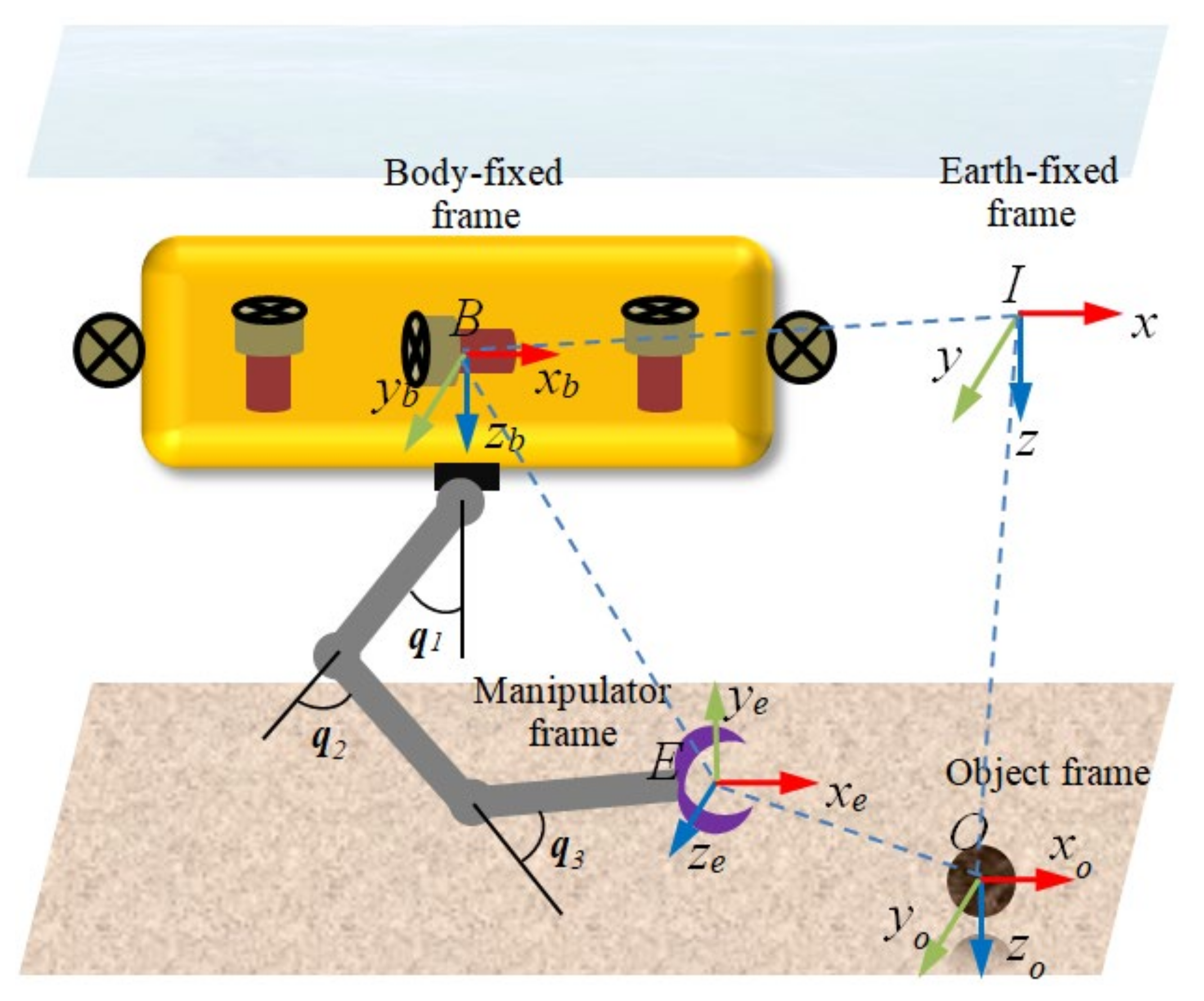
According to the SNAME notation [79], the defined frames are as shown in Figure 2. I(x, y, z) and B(xb, yb, zb) are earth-fixed (inertial) frame and vehicle body-fixed reference frame, respectively. E(xi, yi, zi) is the manipulator-end effector frame and O(xo, yo, zo) is the object reference frame.
First, the vehicle general coordinates are defined in the earth-fixed frame.
η v = η 1 η 2 = [ x y z ϕ θ ψ ] T ,
where η 1 = [ x   y   z ] T represent motion displacement surge, sway and heave, respectively. η 2 = [ ϕ   θ   ψ ] T represent Euler angles roll, pitch and yaw, respectively. Subscript v represents the vehicle. The vector η ˙ v is expressed in the earth-fixed frame, which is the time derivative of the position and attitude η v .
Considering the UVMS equipped with an n-DOF manipulator, q m = [ q 1 q n ] T n × 1 is the vector represents joints position (angle) of the corresponding underwater manipulator links, where n is the number of joints. Subscript m represents manipulator.
Then, define ζ = [ v v T q ˙ m T ] T ( 6 + n ) × 1 as the generalized velocity of the UVMS in the body-fixed frame. The linear and angular velocities of the origin of the body of UVMS in the body-fixed frame are define as
v v = v v ω v 6 × 1 ,
where v v 3 × 1 and ω v 3 × 1 denote the linear and angular velocity of the vehicle in the body-fixed frame.
Therefore, the generalized velocity in the earth-fixed frame can be obtained as follows:
η ˙ v q ˙ m = J ( η v ) ζ ,
The matrix J ( η v ) ( 6 + n ) × ( 6 + n ) is given by:
J ( η v ) = R B I ( η 2 ) O 3 × 3 O 3 × n O 3 × 3 J o ( η 2 ) O 3 × n O n × 3 O n × 3 I n × n ,
in which
R B I ( η 2 ) = c ψ c θ c ψ s ϕ s θ s ψ c ϕ s ψ s ϕ + c ψ s θ c ϕ s ψ c θ c ψ c ϕ + s ψ s θ s ϕ c ψ s ϕ + s ψ s θ c ϕ s θ c θ s ϕ c θ c ϕ
and
J o ( η 2 ) = 1 s ϕ s θ / c θ c ϕ s θ / c θ 0 c ϕ s ϕ 0 s ϕ / c θ c ϕ / c θ
where R B I 3 × 3 is the linear velocity transformation matrix, J o 3 × 3 is the angular velocity transformation matrix with s = sin ( ) and c = cos ( ) . I n × n n × n indicates the identity matrix and O n 1 × n 2 n 1 × n 2 is the null matrix.
Let η e e = [ η e e 1 η e e 2 ] T denote the position and attitude vector of the end effector in the earth-fixed frame. η e e 1 3 × 1 and η e e 2 3 × 1 are the vector represents position and attitude of the end effector, respectively. The relationship between end effector velocity η ˙ e e (expressed in the earth-fixed frame) and generalized velocity ζ (the body-fixed system velocity expressed in the earth-fixed frame) can be obtained by:
η ˙ e e = J k R B I , q m ζ ,
where J k R B I , q m 6 × ( 6 + n ) is the Jacobian matrix of the UVMS.

2.3. Dynamic Equation of UVMS

The dynamic equation of motion in the body-fixed frame of UVMS can be established as follows [7,80]:
M ( η v , q m ) ζ ˙ + C ( η v , q m , ζ ) ζ + D ( η v , q m , ζ ) ζ + G ( η v , q m ) = τ e + τ c ,
in which
M ( η v , q m ) = M v ( η v ) 0 6 × n 0 n × 6 M m ( q m ) , C ( η v , q m , ζ ) = C v ( η v , v v ) 0 0 C m ( q m , q ˙ m ) D ( η v , q m , ζ ) = D v ( η v , v v ) 0 0 D m ( q m , q ˙ m ) , G ( η v , q m ) = G v ( η v ) G m ( q m ) , τ e = τ e v + τ m v τ e m , τ c = τ c v τ c m
where M ( η v , q m ) ( 6 + n ) × ( 6 + n ) is the mass matrix including added mass term, C ( η v , q m , ζ ) ( 6 + n ) × ( 6 + n ) represents the Coriolis and centripetal effects including added mass terms, D ( η v , q m , ζ ) ( 6 + n ) × ( 6 + n ) denotes friction of the links, the hydrodynamic force and damping matrix, G ( η v , q m ) ( 6 + n ) × 1 is the restoring matrix. τ e ( 6 + n ) × 1 represents the external disturbances (such as end effector payloads, ocean currents, etc.,) on the UVMS, τ c ( 6 + n ) × 1 represents the controller input force/torques acting on the vehicle as well as joint. Comparing with single underwater robot and/or base-fixed manipulators, UVMS are more complex due to multi-body coupling and multi-body-fluid coupling effects.

2.4. Configuration of Thrusters

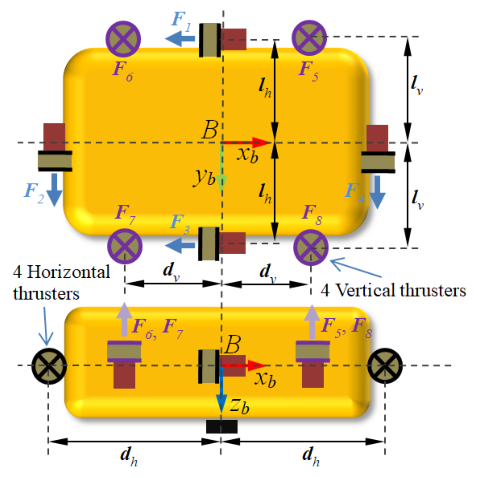
In this paper, the body of UVMS is equipped with eight thrusters as shown in Figure 3. Thus, the 6 DOF motions of vehicle can be controlled by the eight thrusters. Four horizontal thrusters T1, T2, T3, and T4, which are installed at the front, aft and two sides of the vehicle, are responsible for the motions in the horizontal plane. Meanwhile, four vertical thrusters T5, T6, T7, and T8 are responsible for the motions in the horizontal plane.
The relationship between the required force/moment acting on the vehicle in each DOF τ c v and thruster propulsion force τ u is
τ c v = B v τ u ,
where B v 6 × 8 is a thruster control matrix which is related to the thruster configuration. Desired control force/moment τ c v and desired force of each thruster τ u are defined as
τ c v = F v x F v y F v z M v x M v y M v z T ,
τ u = F 1 F 2 F 3 F 4 F 5 F 6 F 7 F 8 T ,
Then, the thruster configuration control matrix B v can be obtained.
B v = 1 0 1 0 0 0 0 0 0 1 0 1 0 0 0 0 0 0 0 0 1 1 1 1 0 0 0 0 l v l v l v l v 0 0 0 0 d v d v d v d v l h d h l h d h 0 0 0 0 ,
in which lv, lh, dv, and dv are the lengths of moment which provide the torque in roll, pitch, and yaw.

2.5. Contact with Environment

If the end effector contacts with the environment (e.g., ground, wall, object, etc.,), the force/moment at the tip of the manipulator acting on the whole UVMS can be expressed as
τ e = J k T R B I , q m h e ,
where J k is the Jacobain matrix defined in Equation (5) and the vector h e 6 × 1 is defined as
h e = f e t e ,
in which f e and t e are the vector of forces and moments at the tip of the manipulator. Therefore, J k is divided into two parts.
J k R B I , q m = J k , p o s R B I , q m J k , o r R B I , q m 6 × ( 6 + 3 ) ,
We only consider the contact force at the end effector in this paper, and J k , p o s R B I , q m 3 × ( 6 + 3 ) . Then combined with Equations (11)–(13) and rewritten contact force equation
τ e = J k , p o s T R B I , q m f e ,
in here, f e = K ( η e e 1 η o ) , K > 0 is the stillness matrix which has different value due to different environment and material, η e e 1 and η o are the position of the tip of end effector and the surface of the object.

2.6. Actuator Saturation

In fact, the actuator and motor control outputs are usually bounded by the thruster and motor physical limits. In here, to simplify this limits, desired control force/moment τ c is bounded.
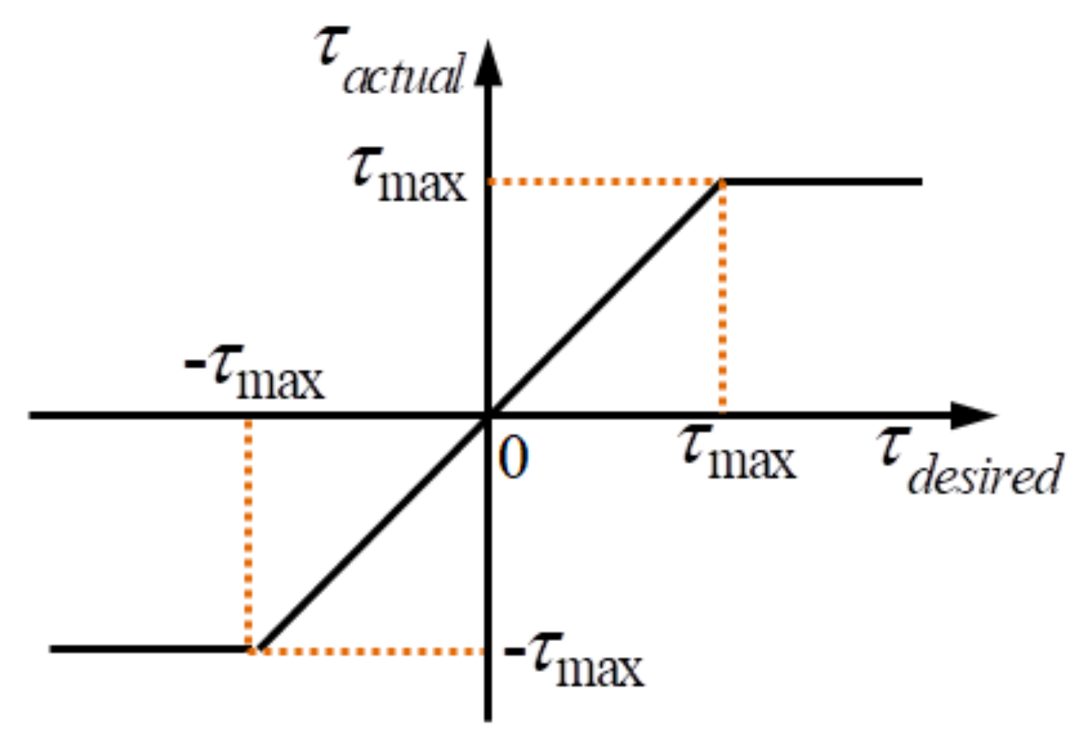
τ c i = τ c i τ c i τ c i , max τ c i , max τ c i > τ c i , max , i = 1 , , ( 6 + n ) ,
where τ c i , max is the maximum control output limit for each DOF of UVMS. Desired input and actual output are shown in Figure 4.
Because of the thruster and motor’s physical limits and constraints, the position of the manipulator, the velocity and acceleration of the UVMS are also bounded by the mechanical and physical limits.
η v i η v i , max , i = 1 , , 6 q i q i , max , i = 1 , , n ζ i ζ i , max , i = 1 , , ( 6 + n ) ζ ˙ i ζ ˙ i , max i = 1 , , ( 6 + n ) ,
where η v i , max , q i , max , ζ i , max and ζ ˙ i , max are the maximum allowed movement limit for each DOF of UVMS.

2.7. Modeling of End Effector Carrying an Object

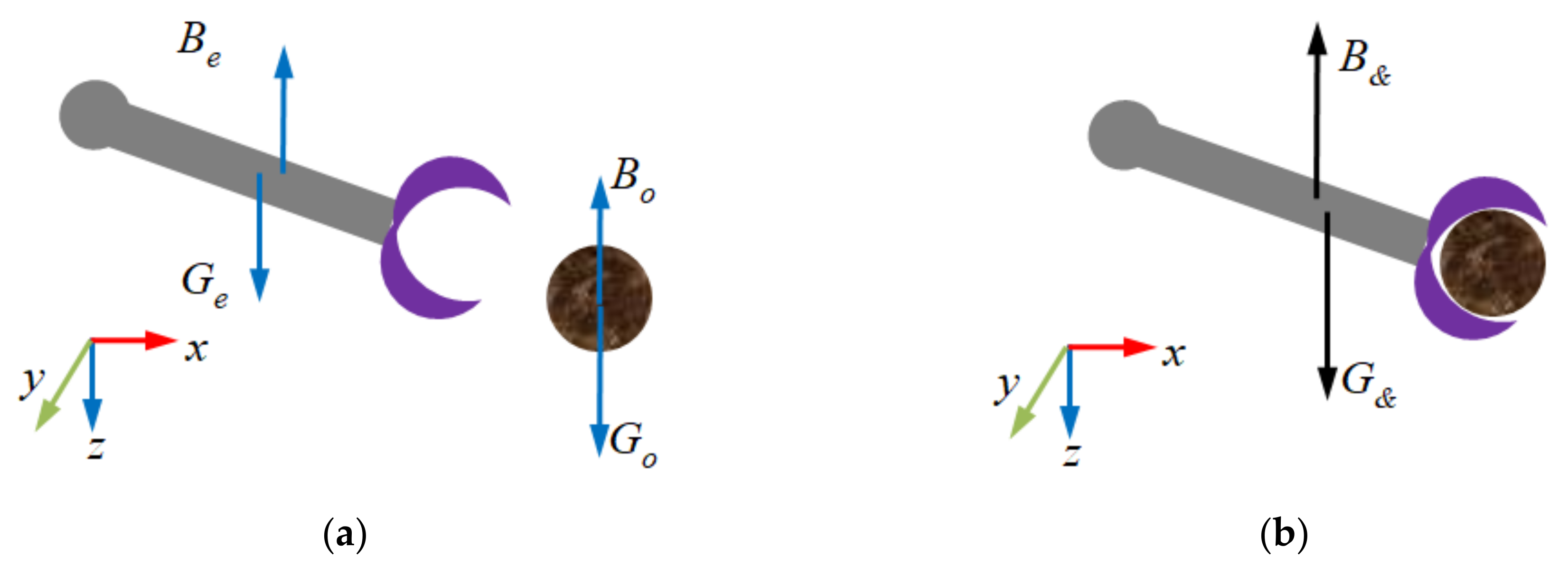
When the end effector of UVMS carries an object, its dynamics are affected (see Figure 5). Hence, the model focuses on the scenario when the end effector has already grasped the body of the object. Therefore, the object is assumed to be fixed in the end effector so that its position and attitude with respect of the end effector or end-link of the manipulator will not change. As a result, the end effector and the object can be modeled as a new rigid body, whose motions can be described by the same equations. However, the dynamic properties of end effector are changed in the process of grasping.
Before end effector grasps the object, the total mass of end effector or end-link of the manipulator is me, its volume is Ve, the centers of buoyancy and gravity in the end effector body-fixed frame are l e g b and l e b b , respectively. Then, the variables relating to the end effector are labeled as e, those relating to the object are labeled as o. Those corresponding to the combined body between end effector and object as &. B = ρ g V and G = m g are buoyancy and gravity of rigid body, respectively. ρ is seawater density and g gravitational acceleration. Hence the volume, mass, and position of the centers of buoyancy and gravity of the total end effector and object can be computed as follows:
V & = V e + V o ,
m & = m e + m o ,
l & b b = V e l e b b + V o l o b b V & ,
l & g b = m e l e g b + m o l o g b m & ,
By using the parallel axis theorem, the inertia matrix of changed end effector referenced to its body-fixed frame can be obtained as:
I & , e b = I e b m e S 2 ( l & g b l e g b ) I & , o b = I o b m o S 2 ( l & g b l o g b ) , I & b = I & , e b + I & , o b
where I e b and I o b are the inertia matrix of each body referenced to their center of gravity, and S ( ) 3 × 3 is the skew symmetric matrix which is defined as follows:
S ( x ) = 0 x 3 x 2 x 3 0 x 1 x 2 x 1 0 ,

3. Proportional-Integral-Derivative (PID) Control and Parameters

In this section, PID control scheme for UVMS system is briefly introduced. Meanwhile, for the next step of the simulation, the main parameters of the model of UVMS and controller are provided.

3.1. Proportional-Integral-Derivative (PID) Control

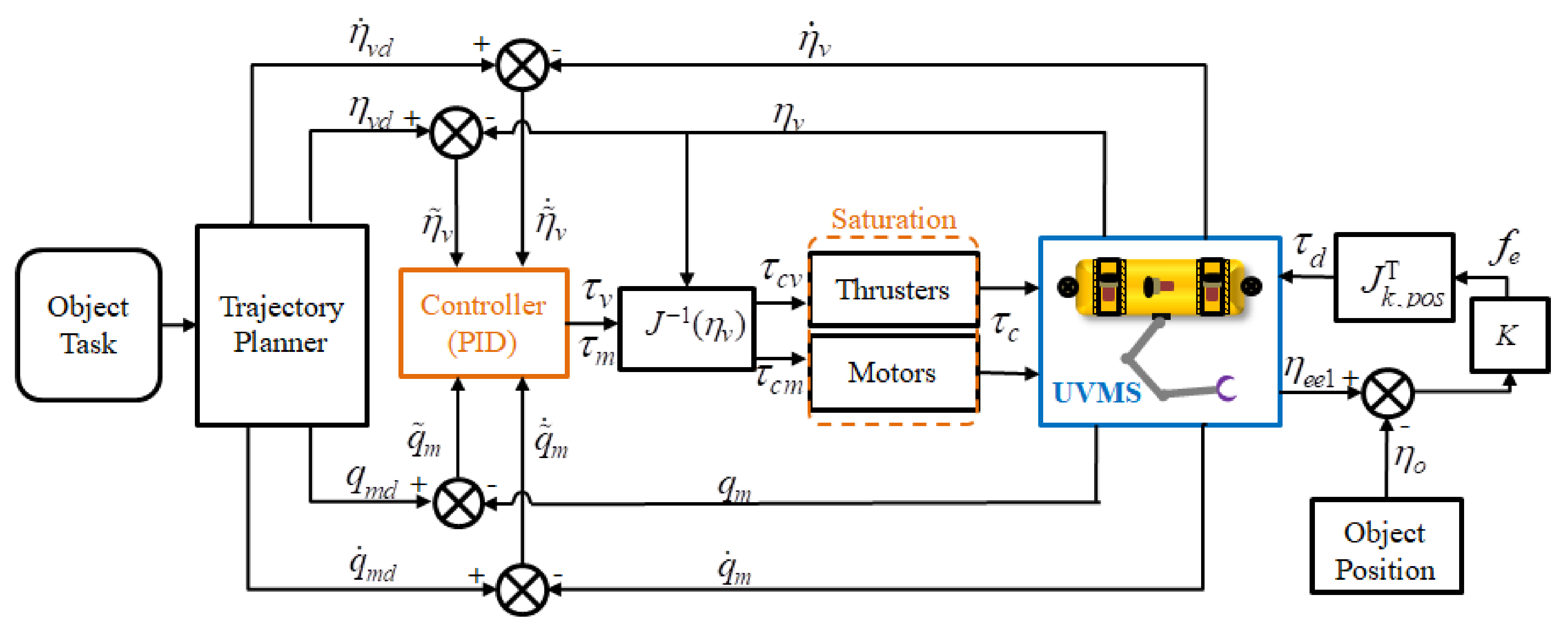
In the process of UVMS grasping an object, the desired trajectory of end effector is planned in the inertial frame. The desired position η e e d , desired velocity η ˙ e e d , and desired acceleration η ¨ e e d of end effector are obtained by the quintic polynomial to generate fifth-order trajectories in task space. According to Equations (3) and (5), the desired position, velocity, and acceleration of the vehicle and manipulator joints in the body-fixed frame and earth-fixed frame can be obtained, respectively. The vector of position and velocity error of trajectory tracking can be expressed as:
η ˜ v q ˜ m = η v d η v q m d q m ,
η ˜ ˙ v q ˜ ˙ m = η ˙ v d η ˙ v q ˙ m d q ˙ m ,
The desired control force/torque acting on vehicle and manipulator joints in the inertial frame can be obtained as:
τ v τ m = K P η ˜ v q ˜ m + K I 0 t η ˜ v ( t ) q ˜ m ( t ) d t + K D η ˜ ˙ v q ˜ ˙ m ,
where K P , K I , and K D are gain matrices and they are diagonal. τ v and τ m are desired control force/torque in inertial frame. Then the control scheme is converted to the body-fixed frame as
τ c = τ c v τ c m = J T ( η v ) τ v τ m ,
where τ c is defined in Equation (6) and its constraints are introduced in Equation (15). The whole control schematic diagram is shown in Figure 6.

3.2. Model Parameters

The parameters of UVMS for simulation are also needed. The data of the vehicle are referred to [81], and some main physical parameters are listed in Table 1.
Because the body of UVMS has three planes of symmetry and the velocity is low, the inertia matrix, including the added mass terms, is given by:
M v = diag 6.019 × 10 3 , 9.551 × 10 3 , 2.332 × 10 4 , 4.129 × 10 3 , 4.913 × 10 4 , 2.069 × 10 4 ,
The hydrodynamic derivatives of the vehicle are given by:
X p p = 2.8 × 10 3 X q q = 5.9 × 10 3 X r r = 1.6 × 10 3 X p r = 2.9 × 10 2 X u ˙ = 5.6 × 10 2 X ω q = 1.5 × 10 4 X v p = 2.2 × 10 2 X v r = 1.5 × 10 3 X v v = 7.4 × 10 2 X ω ω = 2.4 × 10 3 Y p ˙ = 4.7 × 10 1 Y r ˙ = 4.7 × 10 2 Y p q = 1.6 × 10 3 Y p r = 2.6 × 10 3 Y v ˙ = 4.1 × 10 3 Y u p = 2.2 × 10 2 Y r = 2.2 × 10 3 Y v q = 1.8 × 10 3 X ω p = 1.7 × 10 4 Y ω r = 1.4 × 10 3 Y v = 1.4 × 10 3 Y v ω = 9.5 × 10 2 Z q ˙ = 2.7 × 10 3 Z p p = 5.1 × 10 1 Z p r = 2.6 × 10 3 Z r r = 2.9 × 10 2 Z ω ˙ = 1.8 × 10 4 Z u q = 1.0 × 10 4 Z v p = 3.6 × 10 3 Z v r = 3.3 × 10 3 Z u ω = 4.2 × 10 3 Z v v = 9.5 × 10 2 K p ˙ = 2.0 × 10 3 K r ˙ = 7.1 × 10 1 K p q = 1.4 × 10 2 K p r = 3.5 × 10 4 K v ˙ = 4.7 × 10 1 K u p = 4.3 × 10 3 K u r = 3.3 × 10 2 K v q = 2.0 × 10 3 K ω p = 5.1 × 10 1 K ω r = 5.5 × 10 3 K u v = 2.3 × 10 2 K v ω = 1.4 × 10 4 M q ˙ = 3.5 × 10 4 M p p = 1.1 × 10 2 M p r = 1.0 × 10 4 M r r = 6.0 × 10 3 M ω ˙ = 2.7 × 10 3 M u q = 2.7 × 10 4 M v p = 4.7 × 10 2 M v r = 6.7 × 10 3 M u ω = 7.4 × 10 3 M v v = 1.9 × 10 3 N p ˙ = 7.1 × 10 1 N r ˙ = 7.1 × 10 3 N p q = 4.4 × 10 4 , N p r = 5.6 × 10 3 N v ˙ = 4.7 × 10 2 N u p = 3.3 × 10 2 N u r = 6.3 × 10 3 N v q = 3.9 × 10 3 N ω p = 6.7 × 10 3 N ω r = 2.9 × 10 3 N u v = 5.5 × 10 2 N v ω = 2.0 × 10 3
The manipulator is supposed to be mounted under the vehicle in the center of its length, the position of the base of manipulator is [0, 0, 0.5]T m in the vehicle body fixed frame. All the links are modeled as cylinders, the centers of mass and buoyancy of each links are [0, 0, 0.5]T m in their link frame. The volumes of each links are computed as δ i = π L i r i 2 , where L i and r i are the link lengths and radius, respectively. For each of the cylinder the mass is computed as:
M i = diag m i + ρ δ i , m i + ρ δ i , m i + 0.1 m i , I x x , i + ρ L i 2 δ i / 12 , I y y , i + ρ L i 2 δ i / 12 , I z z , i ,
in which the main parameters of manipulator are reported in Table 2. The cylinder length is modeled along the z i axis. The dry friction has not been considered to avoid chattering behavior. The linear skin and quadratic drag coefficients are given by D s = 0.4 and C d = 0.6 , respectively.
Assuming that the object modeled is considered as a sphere, and its parameters are reported in Table 3. It is obvious that the weight of the object is greater than its buoyancy.

3.3. Controller Parameters

Assume that the body of UVMS mounts thrusters can control vehicle translation and rotation (see Figure 2 and Figure 3). For PID control, high gains can improve the controller response due to small trajectory tracking error. However, it will have different gains in different system. In this paper, the controller parameters that we choose for this UVMS simulation system are as follows:
K P = diag { 4000 , 4000 , 6000 , 50 , 000 , 50 , 000 , 50 , 000 , 4000 , 1000 , 500 } K I = diag { 0.2 , 0.2 , 0.5 , 5 , 3.55 , 3 , 2 , 1 , 0.5 } , K D = diag { 8000 , 8000 , 20 , 000 , 50 , 000 , 65 , 000 , 50 , 000 , 2000 , 500 , 200 }

4. Simulation and Discussion

The ocean environment (wind, waves, and currents) and disturbance force which affect the UVMS dynamics are neglected in this paper. Although the UVMS model is built in the three dimensional space, to simplify the problem, the motion of the UVMS and object are simulated only in the vertical plane. Therefore, the sway, roll, and yaw motions of the vehicle are always zero. In order to indicate that the motion of the manipulator has an impact on the vehicle, before two cases vehicle control (with/without attitude control), all thrusters do not work. Then with and without attitude control of vehicle is considered and performed. UVMS is under-actuated system when the vehicle is without attitude control, however, UVMS is fully actuated system when the vehicle is with attitude control.

4.1. Simulations

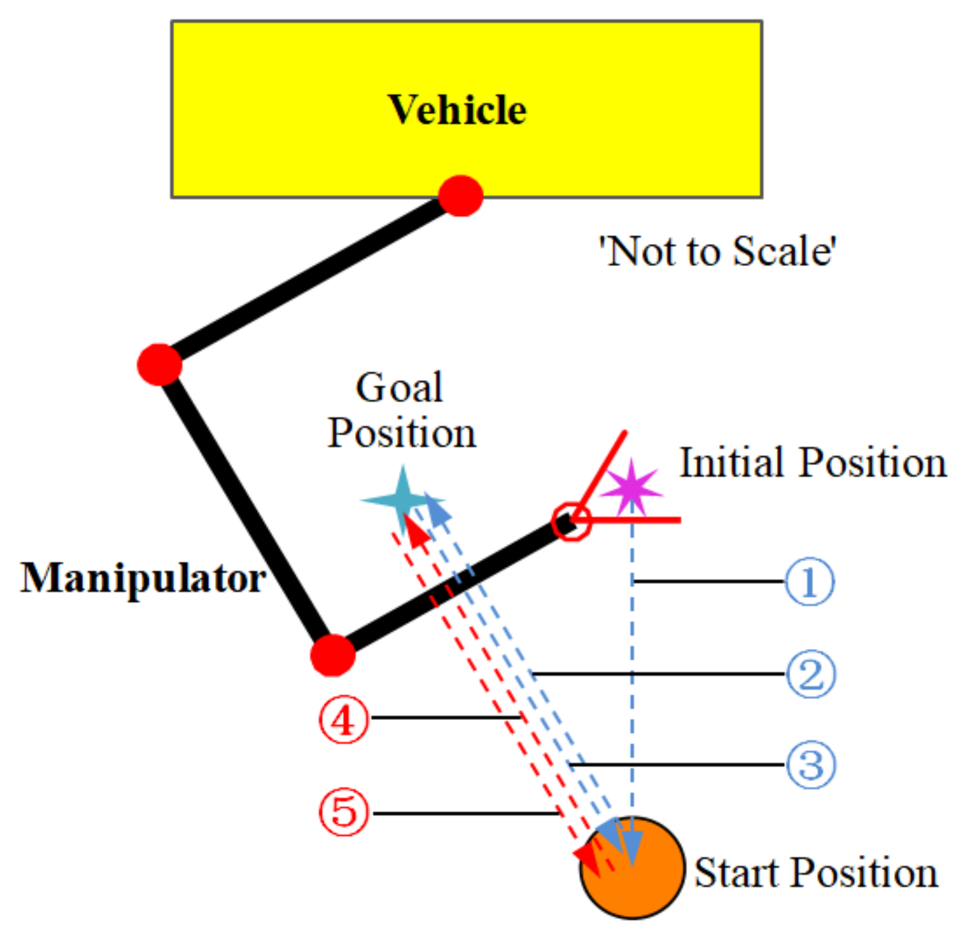
The UVMS trajectory is planned with moving the end effector along a straight line in the absence of currents. Comparison simulation task is to pick up the object at start position [0.5, 0, 2.5]T m by the UVMS with the initial position and attitude of vehicle [0, 0, 0, 0, 0, 0]T m or deg and the initial configuration of manipulator [−60, 90, 90]T deg. The goal position of the object is at [0, 0, 1.5]T m. The whole process of manipulator for grasping and carrying the object is shown in Figure 7, and the time process is listed in Table 4.
The desired motion of the vehicle is to keep stationary and only rotate manipulator joint. The desired position and attitude of vehicle η v d , the desired velocity of vehicle η ˙ v d , the desired angle of manipulator joints q m d , and the desired angular velocity of manipulator joints q ˙ m d are planned by trajectory planner using the quintic polynomial. The processes of grasping are simulated using MATLAB software. The total simulation time is 90 s and time step is 0.01 s.
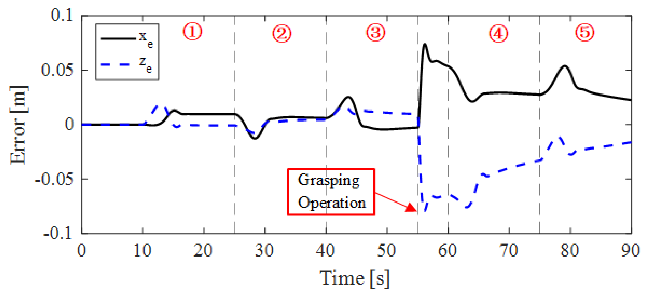
The condition that the vehicle is floating and the thrusters cannot work to keep the vehicle position stationary while operation of manipulator is considered first. Through numerical simulation, the actual position of the vehicle is shown in Figure 8. During the motion of the manipulator, the vehicle moves due to the coupling effect between the manipulator and the vehicle. This results in the actual distance between the tip of end effector and the position of start object position to exceed 10 cm when picking up the object at t = 55 s (Figure 9). Hence, the grasping task cannot be completed without vehicle control.

4.1.1. Case-I: Without Attitude Control for Vehicle

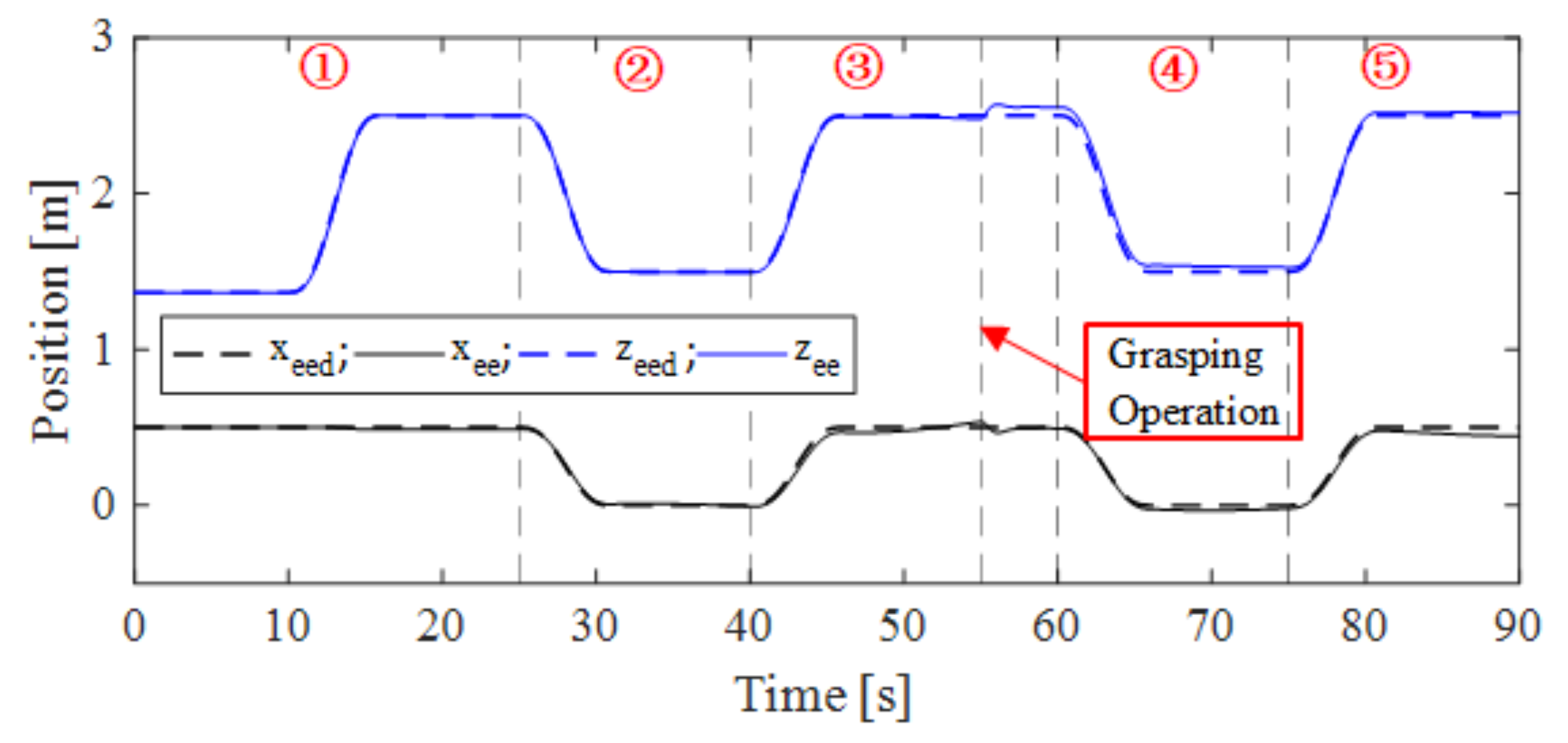
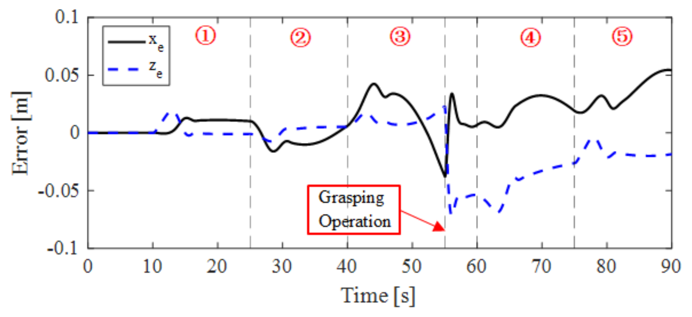
The roll and pitch of the body of UVMS are hydrostatically stable because the center of gravity of the vehicle is below the center of its buoyancy. When only the position of the vehicle is controlled, the whole UVMS system is under-actuated. In this situation, the desired control torque for control the attitude of the vehicle is set as zero. The desired and actual position of end effector responses are shown in Figure 10, and the position trajectory tracking error of end effector is shown in Figure 11.
From Figure 10 and Figure 11, when the manipulator is picking up the object (at t = 55 s), the distance between the tip of manipulator and the object is 4.39 cm. Although the vehicle attitude is not controlled, the distance error of the end effector can be acceptable. Hence, in this case the grasping task can be completed.

4.1.2. Case-II: With Attitude Control for Vehicle

For a fully actuated UVMS, the position and attitude of vehicle are controlled. Under this situation, the process of grasping operation is simulated. The desired and actual position of end effector responses are shown in Figure 12, and the position trajectory tracking error of end effector is shown in Figure 13.
From Figure 12 and Figure 13, when the manipulator picking up the object (at t = 55 s), the distance between the tip of manipulator and the object is 1.02 cm. Under full control of the vehicle, the position and attitude of vehicle vary over a small range. Hence, the grasping task in this situation can also be completed.

4.2. Results and Discussions

Without the control for vehicle, the operation of manipulator cannot be completed for the coupling effect between the vehicle and the manipulator. Hence comparative analyses of Case-I and Case-II are carried out. Due to the manipulator only moves in the vertical plane, the vehicle position y and vehicle Euler angle ϕ and ψ are always zero. So, the trajectory of UVMS can be shown in Figure 14. The results show that PID control scheme is able to suit system dynamics changing and control UVMS carrying an object successfully.
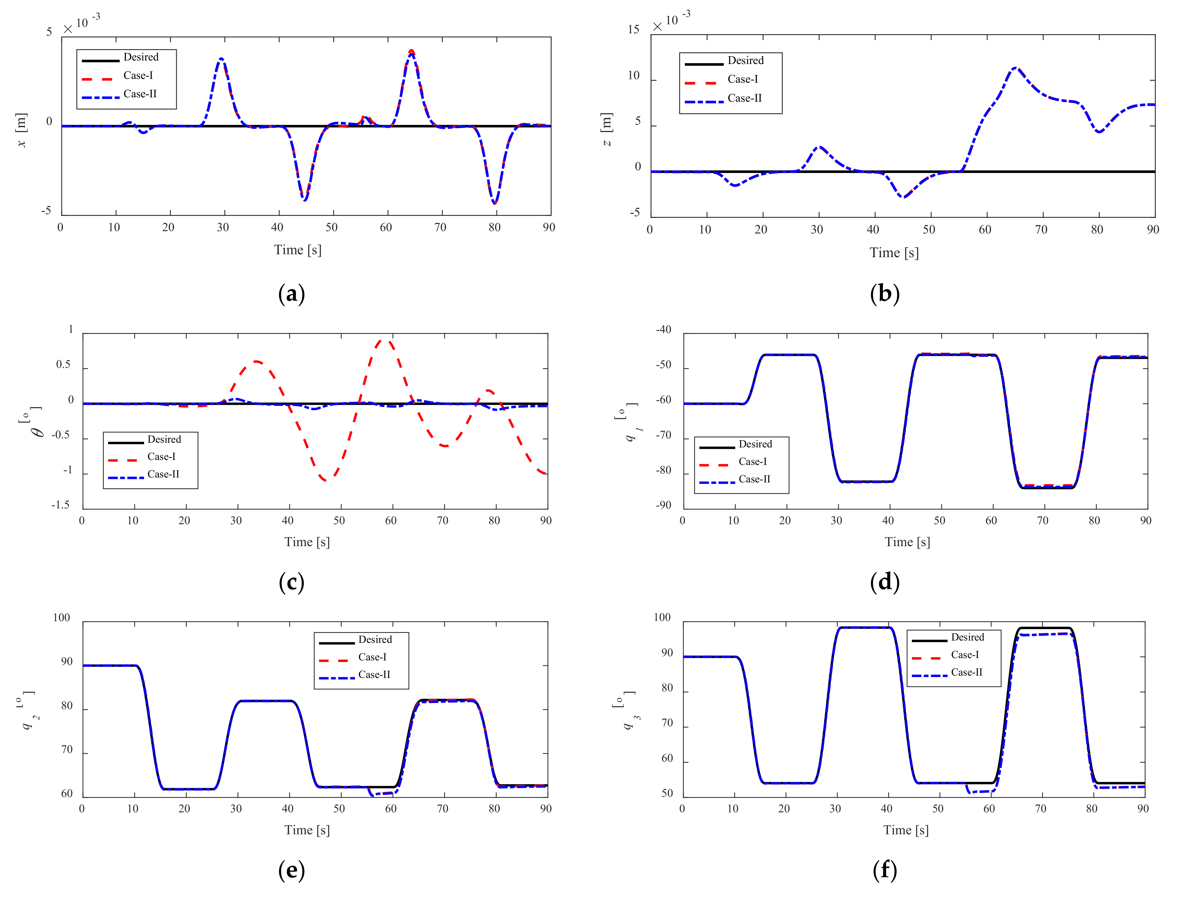
The position of vehicle x and z , the Euler (pitch) angle of vehicle θ , and manipulator joints q responses are shown in Figure 15. Their tracking errors are shown in Figure 16.
From Figure 15 and Figure 16, the pitch angle of the vehicle with fully controlled is less than only control for position. However, hydrostatically stable makes the vehicle pitch angle vary within a certain range below 2 deg (see Figure 15c). The trajectories tracking errors are close in two cases except the attitude error of the vehicle.
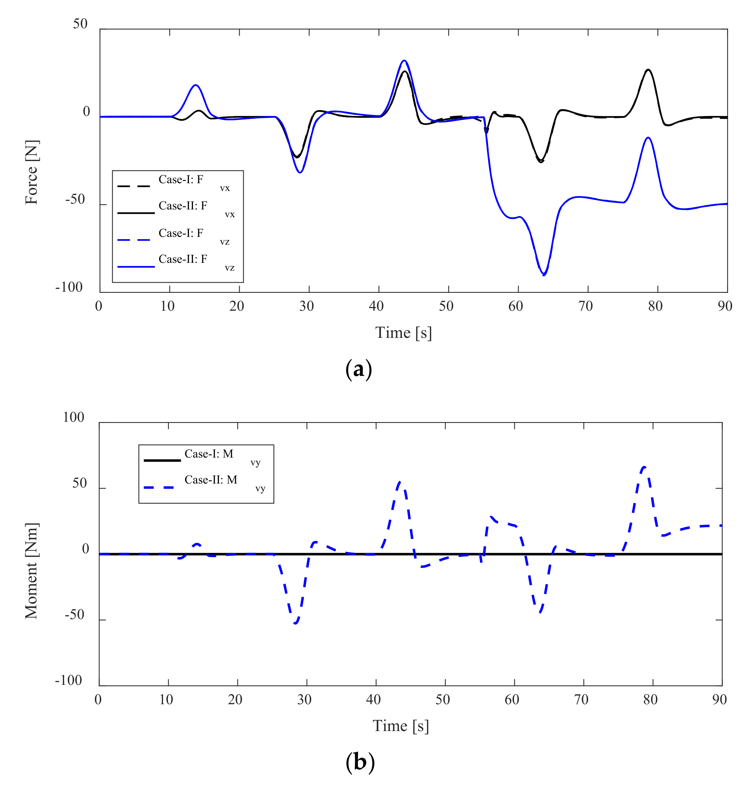
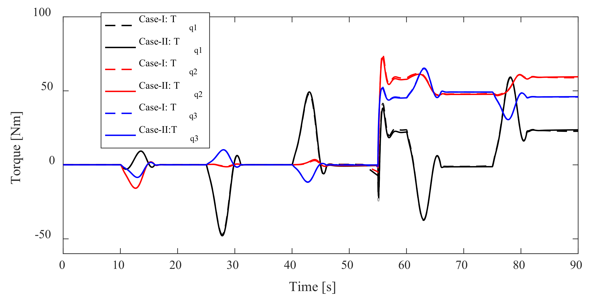
Besides, the forces and moments of the vehicle and joint torques of the manipulator are shown in Figure 17 and Figure 18, respectively. We can find that none of the control forces and moments exceed the limit in Table 1 and Table 2. Similarly, the forces acting on the vehicle and joint torques of the manipulator show a small difference in the two cases. Because the attitude of the vehicle is not controlled in Case-I, the moment acting on the vehicle is always zero.
According to the root mean square error (RMSE) between actual and desired trajectories over the whole simulation duration for the two types of analyzed situation, the values of RMSE of the position and attitude of the vehicle (V-X, V-Z, V- θ ), the manipulator joint angles (q1, q2, q3), and the position error of end effector (EE-X, EE-Z) are shown in Figure 19.
Due to vehicle attitude control, the values of RMSE of vehicle attitude are different in two cases. It is obvious that with vehicle attitude control can reduce attitude trajectory tracking error effectively. However, there is an interesting thing that the values of RMSE of end effector with vehicle attitude control are greater than without attitude control. This phenomenon shows that it may be because of the fixed PID parameters and the hydrostatic restoring force/moment of the vehicle. On the one hand, the system parameters of UVMS are changed, but PID parameters are fixed. On the other hand, the input attitude control force/moment and hydrostatic restoring force/moment affect each other, and this effect deteriorates the positioning accuracy of the end effector.
Therefore, different control schemes and different grasping situations should be considered and analyzed in the future. In this paper, the vehicle and each joint of manipulator are assumed to be neutral buoyancy, so, it is hard to achieve in reality. Hence, the motion planning of the vehicle and the manipulator should be carried out when dynamic grasping, for example minimizing restoring moments method [26] and zero moment point method [27]. Further experiments should be performed in future to verify the correctness of the theoretical and simulation results.

5. Conclusions

Considering the dynamic coupling of the manipulator and the vehicle, interaction between the manipulator and the object, actuator saturation, and so on, dynamic simulation of the process of UVMS grasping an object is carried out and two case studies that without/with vehicle attitude control are analyzed and compared in this article. Some conclusions are summarized as follows.
(1)
The position and attitude of the vehicle cannot remain stationary due to the coupling effect between the manipulator and the vehicle. It deteriorates the positioning accuracy of the end effector of the manipulator and is harmful to underwater precision operations or other task.
(2)
Trajectory tracking errors and forces/moments acting on the UVMS under fully controlled are performed in comparison with vehicle position control. Vehicle fully controlled can reduce attitude trajectory tracking error effectively.
(3)
The hydrostatic restoring force/moment is helpful for the stability of the UVMS system. However, the combined effect between hydrostatic restoring force/moment and system control force will affect the precise positioning of the end effector.
In the future, different control schemes and different grasping situations should be considered and analyzed. The motion planning of the vehicle and the manipulator should be carried out in the process of grasping. experiments should be performed to verify the correctness of the theoretical and simulation results.

Author Contributions

Conceptualization, Z.C. and Y.Z.; formal analysis, K.S.; methodology, Y.Z.; software, Y.Z.; supervision, Z.C.; validation, Z.C., Z.Z. and L.Z.; writing—original draft, Z.C. and Y.Z.; writing—review and editing, Z.C., Y.Z., Z.Z. and K.S. All authors have read and agreed to the published version of the manuscript.

Funding

This research is supported by National Natural Science Foundation of China (Grant No.: 51875540).

Institutional Review Board Statement

Not applicable.

Informed Consent Statement

Not applicable.

Data Availability Statement

Not applicable.

Acknowledgments

The valuable comments from the anonymous reviewers are highly appreciated.

Conflicts of Interest

The authors declare no conflict of interest.

References

  1. Lin, M.; Yang, C. Ocean observation technologies: A review. Chin. J. Mech. Eng. 2020, 33, 33–50. [Google Scholar] [CrossRef] [Green Version]
  2. Xu, H.; Jiang, C. Heterogeneous oceanographic exploration system based on USV and AUV: A survey of developments and challenges. J. Univ. Chin. Acad. Sci. 2021, 38, 145–159. [Google Scholar] [CrossRef]
  3. Van, M.; Bui, D.H.P.; Do, Q.T.; Huynh, T.T.; Lee, S.D.; Choi, H.S. Study on dynamic behavior of unmanned surface vehicle-linked unmanned underwater vehicle system for underwater exploration. Sensors 2020, 20, 1329. [Google Scholar] [CrossRef] [Green Version]
  4. Cai, M.; Wang, Y.; Wang, S.; Wang, R.; Ren, Y.; Tan, M. Grasping marine products with hybrid-driven underwater vehicle-manipulator system. IEEE Trans. Autom. Sci. Eng. 2020, 17, 1443–1454. [Google Scholar] [CrossRef]
  5. Vu, M.T.; Thanh, H.L.N.N.; Huynh, T.T.; Thang, Q.; Duc, T.; Hoang, Q.D.; Le, T.H. Station-keeping control of a hovering over-actuated autonomous underwater vehicle under ocean current effects and model uncertainties in horizontal plane. IEEE Access 2021, 9, 6855–6867. [Google Scholar] [CrossRef]
  6. Simetti, E.; Campos, R.; Vito, D.D.; Quintana, J.; Antonelli, G.; Garcia, R.; Turetta, A. Sea mining exploration with an UVMS: Experimental validation of the control and perception framework. IEEE ASME Trans. Mechatron. 2021, 26, 1635–1645. [Google Scholar] [CrossRef]
  7. Dunnigan, M.W.; Russell, G.T. Evaluation and reduction of the dynamic coupling between a manipulator and an underwater vehicle. IEEE J. Ocean. Eng. 1998, 23, 260–273. [Google Scholar] [CrossRef]
  8. McLain, T.W.; Rock, S.M.; Lee, M.J. Experiments in the coordinated control of an underwater arm/vehicle system. Auton. Robot. 1996, 3, 213–232. [Google Scholar] [CrossRef]
  9. Huang, H.; Zhang, G.C.; Li, J.Y.; Zhang, Q.; Xu, J.Y.; Qin, H.D. Model based adaptive control and disturbance compensation for underwater vehicles. Chin. J. Mech. Eng. 2018, 31, 114–126. [Google Scholar] [CrossRef] [Green Version]
  10. Pi, R.; Cieślak, P.; Ridao, P.; Sanz, P.J. TWINBOT: Autonomous underwater cooperative transportation. IEEE Access 2021, 9, 37668–37684. [Google Scholar] [CrossRef]
  11. Evans, J.; Redmond, P.; Plakas, C.; Hamilton, K.; Lane, D. Autonomous docking for intervention-AUVs using sonar and video-based real-time 3D pose estimation. In Proceedings of the MTS/IEEE Oceans 2003, San Diego, CA, USA, 22–26 September 2003; pp. 2201–2210. [Google Scholar] [CrossRef]
  12. Lane, D.M.; Davies, J.B.C.; Robinson, G.; O’Brien, D.J.; Sneddon, J.; Seaton, E.; Elfstrom, A. The AMADEUS dextrous subsea hand: Design, modeling, and sensor processing. IEEE J. Ocean. Eng. 1999, 24, 96–111. [Google Scholar] [CrossRef]
  13. Marani, G.; Choi, S.K.; Yuh, J. Underwater autonomous manipulation for intervention missions AUVs. Ocean Eng. 2009, 36, 15–23. [Google Scholar] [CrossRef]
  14. Ribas, D.; Ridao, P.; Turetta, A.; Melchiorri, C.; Palli, G.; Fernández, J.J.; Sanz, P.J. I-AUV mechatronics integration for the TRIDENT FP7 project. IEEE ASME Trans. Mechatron. 2015, 20, 2583–2592. [Google Scholar] [CrossRef]
  15. Sivčev, S.; Coleman, J.; Omerdić, E.; Dooly, G.; Toal, D. Underwater manipulators: A review. Ocean Eng. 2018, 163, 431–450. [Google Scholar] [CrossRef]
  16. Huang, H.; Zhou, Z.; Li, J.; Tang, Q.; Zhang, W.; Gang, W. Investigation on the mechanical design and manipulation hydrodynamics for a small sized, single body and streamlined I-AUV. Ocean Eng. 2019, 186, 106106. [Google Scholar] [CrossRef]
  17. Tang, C.; Wang, Y.; Wang, S.; Wang, R.; Tan, M. Floating autonomous manipulation of the underwater biomimetic vehicle-manipulator system: Methodology and verification. IEEE Trans. Ind. Electron. 2018, 65, 4861–4870. [Google Scholar] [CrossRef]
  18. Farivarnejad, H.; Moosavian, S.A.A. Multiple impedance control for object manipulation by a dual arm underwater vehicle–manipulator system. Ocean Eng. 2014, 89, 82–98. [Google Scholar] [CrossRef]
  19. Birk, A.; Doernbach, T.; Müller, C.A.; Łuczynski, T.; Chavez, A.G.; Koehntopp, D.; Kupcsik, A.; Calinon, S.; Tanwani, A.K.; Antonelli, G.; et al. Dexterous underwater manipulation from onshore locations: Streamlining efficiencies for remotely operated underwater vehicles. IEEE Robot. Autom. Mag. 2018, 25, 24–33. [Google Scholar] [CrossRef]
  20. Khatib, O.; Yeh, X.; Brantner, G.; Soe, B.; Kim, B.; Ganguly, S.; Stuart, H.; Wang, S.; Cutkosky, M.; Edsinger, A.; et al. Ocean one: A robotic avatar for oceanic discovery. IEEE Robot. Autom. Mag. 2016, 23, 20–29. [Google Scholar] [CrossRef]
  21. Manley, J.E.; Halpin, S.; Radford, N.; Ondler, M. Aquanaut: A new tool for subsea inspection and intervention. In Proceedings of the OCEANS 2018 MTS/IEEE Charleston, Charleston, SC, USA, 22–25 October 2018; pp. 1–4. [Google Scholar] [CrossRef]
  22. Marani, G.; Yuh, J. Introduction to Autonomous Manipulation: Case Study with an Underwater Robot, SAUVIM; Springer: New York, NY, USA, 2014. [Google Scholar]
  23. Ribas, D.; Palomeras, N.; Ridao, P.; Carreras, M.; Mallios, A. Girona 500 AUV: From survey to intervention. IEEE ASME Trans. Mechatron. 2012, 17, 46–53. [Google Scholar] [CrossRef]
  24. Sarkar, N.; Podder, T.K. Coordinated motion planning and control of autonomous underwater vehicle-manipulator systems subject to drag optimization. IEEE J. Ocean. Eng. 2001, 26, 228–239. [Google Scholar] [CrossRef]
  25. Antonelli, G.; Chiaverini, S. Fuzzy redundancy resolution and motion coordination for underwater vehicle-manipulator systems. IEEE Trans. Fuzzy Syst. 2003, 11, 109–120. [Google Scholar] [CrossRef]
  26. Han, J.; Park, J.; Chung, W.K. Robust coordinated motion control of an underwater vehicle-manipulator system with minimizing restoring moments. Ocean Eng. 2011, 38, 1197–1206. [Google Scholar] [CrossRef]
  27. Kang, J.I.; Choi, H.S.; Duc, N.N.; Ji, D.H.; Kim, J.Y. Experimental study of dynamic stability of underwater vehicle-manipulator system using zero moment point. J. Mar. Sci. Tech. 2017, 25, 767–774. [Google Scholar] [CrossRef]
  28. Zhang, M.J.; Peng, S.Q.; Chu, Z.Z.; Wang, Y.J. Motion planning of underwater vehicle-manipulator system with joint limit. Appl. Mech. Mater. 2012, 220–223, 1767–1771. [Google Scholar] [CrossRef]
  29. Sotiropoulos, P.; Kolonias, V.; Aspragathos, N.; Housos, E. Rapid motion planning algorithm for optimal UVMS interventions in semi-structured environments using gpus. Robot. Auton. Syst. 2015, 74, 15–29. [Google Scholar] [CrossRef]
  30. Youakim, D.; Ridao, P. Motion planning survey for autonomous mobile manipulators underwater manipulator case study. Robot. Auton. Syst. 2018, 107, 20–44. [Google Scholar] [CrossRef]
  31. Liu, J.; Du, J. Composite learning tracking control for underactuated autonomous underwater vehicle with unknown dynamics and disturbances in three-dimension space. Appl. Ocean Res. 2021, 112, 102686. [Google Scholar] [CrossRef]
  32. Korkmaz, O.; Ider, S.K.; Ozgoren, M.K. Trajectory tracking control of an underactuated underwater vehicle redundant manipulator system. Asian J. Control 2016, 18, 1593–1607. [Google Scholar] [CrossRef]
  33. Mohan, S.; Kim, J. Indirect adaptive control of an autonomous underwater vehicle-manipulator system for underwater manipulation tasks. Ocean Eng. 2012, 54, 233–243. [Google Scholar] [CrossRef]
  34. Mohan, S.; Kim, J. Coordinated motion control in task space of an autonomous underwater vehicle—manipulator system. Ocean Eng. 2015, 104, 155–167. [Google Scholar] [CrossRef]
  35. Han, H.; Wei, Y.; Ye, X.; Liu, W. Motion planning and coordinated control of underwater vehicle-manipulator systems with inertial delay control and fuzzy compensator. Appl. Sci. Basel 2020, 10, 3944. [Google Scholar] [CrossRef]
  36. Barbalata, C.; Dunnigan, M.W.; Petillot, Y. Coupled and decoupled force/motion controllers for an underwater vehicle-manipulator system. J. Mar. Sci. Eng. 2018, 6, 96. [Google Scholar] [CrossRef] [Green Version]
  37. Huang, H.; Tang, Q.; Li, J.; Zhang, W.; Bao, X.; Zhu, H.; Wang, G. A review on underwater autonomous environmental perception and target grasp, the challenge of robotic organism capture. Ocean Eng. 2020, 195, 106644. [Google Scholar] [CrossRef]
  38. Conti, R.; Fanelli, F.; Meli, E.; Ridolfi, A.; Costanzi, R. A free floating manipulation strategy for autonomous underwater vehicles. Robot. Auton. Syst. 2017, 87, 133–146. [Google Scholar] [CrossRef]
  39. Anderlini, E.; Parker, G.G.; Thomas, G. Control of a ROV carrying an object. Ocean Eng. 2018, 165, 307–318. [Google Scholar] [CrossRef]
  40. Londhe, P.S.; Mohan, S.; Patre, B.M.; Waghmare, L.M. Robust task-space control of an autonomous underwater vehicle-manipulator system by PID-like fuzzy control scheme with disturbance estimator. Ocean Eng. 2017, 139, 1–13. [Google Scholar] [CrossRef]
  41. Taira, Y.; Sagara, S.; Oya, M. Model-based motion control for underwater vehicle-manipulator systems with one of the three types of servo subsystems. Artif. Life Robot. 2019, 25, 133–148. [Google Scholar] [CrossRef]
  42. Wang, J.; Hung, J.Y. Adaptive backstepping control for an underwater vehicle manipulator system using fuzzy logic. In Proceedings of the IECON 2018—44th Annual Conference of the IEEE Industrial Electronics Society, Washington, DC, USA, 21–23 October 2018; pp. 5600–5606. [Google Scholar] [CrossRef]
  43. Yang, C.; Yao, F.; Zhang, M.-J. Adaptive Backstepping Terminal Sliding Mode Control Method Based on Recurrent Neural Networks for Autonomous Underwater Vehicle. Chin. J. Mech. Eng. 2018, 31, 110. [Google Scholar] [CrossRef] [Green Version]
  44. Von Ellenrieder, K.D. Stable Backstepping Control of Marine Vehicles with Actuator Rate Limits and Saturation. IFAC-PapersOnLine 2018, 51, 262–267. [Google Scholar] [CrossRef]
  45. Mohan, S. Proportional-Derivative Observer-Based Backstepping Control for an Underwater Manipulator. Math. Probl. Eng. 2011, 2011, 397092. [Google Scholar] [CrossRef]
  46. Dai, Y.; Yu, S.; Yan, Y.; Yu, X. An EKF-Based Fast Tube MPC Scheme for Moving Target Tracking of a Redundant Underwater Vehicle-Manipulator System. IEEE/ASME Trans. Mechatron. 2019, 24, 2803–2814. [Google Scholar] [CrossRef]
  47. Gong, P.; Yan, Z.; Zhang, W.; Tang, J. Lyapunov-based model predictive control trajectory tracking for an autonomous underwater vehicle with external disturbances. Ocean Eng. 2021, 232, 109010. [Google Scholar] [CrossRef]
  48. Yan, Z.; Gong, P.; Zhang, W.; Wu, W. Model predictive control of autonomous underwater vehicles for trajectory tracking with external disturbances. Ocean Eng. 2020, 217, 107884. [Google Scholar] [CrossRef]
  49. Nikou, A.; Verginis, C.K.; Heshmati-Alamdari, S.; Dimarogonas, D.V. A robust non-linear MPC framework for control of underwater vehicle manipulator systems under high-level tasks. IET Control. Theory Appl. 2021, 15, 323–337. [Google Scholar] [CrossRef]
  50. Esfahani, H.N. Robust model predictive control for autonomous underwater vehicle-manipulator system with fuzzy com-pensator. Pol. Marit. Res. 2019, 26, 104–114. [Google Scholar] [CrossRef] [Green Version]
  51. Song, D.; Hou, R.; Li, C.; Hung, J.Y.; Wang, J. Complementary Constrained Model Predictive Depth Control of a Hybridly-Actuated Submarine Drifter. IEEE Access 2020, 8, 151692–151704. [Google Scholar] [CrossRef]
  52. Cao, Y.; Li, B.; Li, Q.; Stokes, A.A.; Ingram, D.M.; Kiprakis, A. A Nonlinear Model Predictive Controller for Remotely Operated Underwater Vehicles with Disturbance Rejection. IEEE Access 2020, 8, 158622–158634. [Google Scholar] [CrossRef]
  53. Han, L.; Tang, G.; Cheng, M.; Huang, H.; Xie, D. Adaptive Nonsingular Fast Terminal Sliding Mode Tracking Control for an Underwater Vehicle-Manipulator System with Extended State Observer. J. Mar. Sci. Eng. 2021, 9, 501. [Google Scholar] [CrossRef]
  54. El-Ferik, S.; Elkhider, S.; Ghommam, J. Adaptive containment control of multi-leader fleet of underwater vehicle-manipulator autonomous systems carrying a load. Int. J. Syst. Sci. 2019, 50, 1501–1516. [Google Scholar] [CrossRef]
  55. Gao, J.; Liang, X.; Chen, Y.; Zhang, L.; Jia, S. Hierarchical image-based visual serving of underwater vehicle manipulator systems based on model predictive control and active disturbance rejection control. Ocean Eng. 2021, 229, 108814. [Google Scholar] [CrossRef]
  56. Xie, T.; Li, Y.; Jiang, Y.; An, L.; Wu, H. Backstepping active disturbance rejection control for trajectory tracking of underactuated autonomous underwater vehicles with position error constraint. Int. J. Adv. Robot. Syst. 2020, 17, 397092. [Google Scholar] [CrossRef] [Green Version]
  57. Heshmati-Alamdari, S.; Bechlioulis, C.P.; Karras, G.C.; Nikou, A.; Dimarogonas, D.V.; Kyriakopoulos, K.J. A robust interaction control approach for underwater vehicle manipulator systems. Annu. Rev. Control. 2018, 46, 315–325. [Google Scholar] [CrossRef]
  58. Bai, X.; Wang, Y.; Wang, R.; Wang, S.; Tan, M. Dynamic surface control for an underactuated underwater biomimetic vehicle-manipulator system. In Proceedings of the 2021 IEEE International Conference on Real-time Computing and Robotics (RCAR), Xining, China, 15–19 July 2021; pp. 205–210. [Google Scholar] [CrossRef]
  59. Von Ellenrieder, K.D. Dynamic surface control of trajectory tracking marine vehicles with actuator magnitude and rate limits. Automatica 2019, 105, 433–442. [Google Scholar] [CrossRef]
  60. Dai, P.; Lu, W.; Le, K.; Liu, D. Sliding Mode Impedance Control for contact intervention of an I-AUV: Simulation and experimental validation. Ocean Eng. 2020, 196, 106855. [Google Scholar] [CrossRef]
  61. Rojsiraphisal, T.; Mobayen, S.; Asad, J.H.; Vu, M.T.; Chang, A.; Puangmalai, J. Fast Terminal Sliding Control of Underactuated Robotic Systems Based on Disturbance Observer with Experimental Validation. Mathematics 2021, 9, 1935. [Google Scholar] [CrossRef]
  62. Zhou, Z.; Tang, G.; Huang, H.; Han, L.; Xu, R. Adaptive nonsingular fast terminal sliding mode control for underwater manipulator robotics with asymmetric saturation actuators. Control. Theory Technol. 2020, 18, 81–91. [Google Scholar] [CrossRef]
  63. Liu, X.; Zhang, M.; Chen, J.; Yin, B. Trajectory tracking with quaternion-based attitude representation for autonomous underwater vehicle based on terminal sliding mode control. Appl. Ocean Res. 2020, 104, 102342. [Google Scholar] [CrossRef]
  64. Wang, Y.; Li, B.; Yan, F.; Chen, B. Practical adaptive fractional-order nonsingular terminal sliding mode control for a cable-driven manipulator. Int. J. Robust Nonlinear Control. 2019, 29, 1396–1417. [Google Scholar] [CrossRef]
  65. Vu, M.T.; Le, T.-H.; Thanh, H.L.N.N.; Huynh, T.-T.; Van, M.; Hoang, Q.-D.; Do, T.D. Robust Position Control of an Over-actuated Underwater Vehicle under Model Uncertainties and Ocean Current Effects Using Dynamic Sliding Mode Surface and Optimal Allocation Control. Sensors 2021, 21, 747. [Google Scholar] [CrossRef]
  66. Thanh, H.L.N.N.; Vu, M.T.; Mung, N.X.; Nguyen, N.P.; Phuong, N.T. Perturbation Observer-Based Robust Control Using a Multiple Sliding Surfaces for Nonlinear Systems with Influences of Matched and Unmatched Uncertainties. Math. 2020, 8, 1371. [Google Scholar] [CrossRef]
  67. Muñoz, F.; Cervantes-Rojas, J.; Valdovinos, J.; Sandre-Hernández, O.; Salazar, S.; Romero, H. Dynamic Neural Network-Based Adaptive Tracking Control for an Autonomous Underwater Vehicle Subject to Modeling and Parametric Uncertainties. Appl. Sci. 2021, 11, 2797. [Google Scholar] [CrossRef]
  68. Mu, W.; Wang, Y.; Sun, H.; Liu, G. Double-Loop Sliding Mode Controller with An Ocean Current Observer for the Trajectory Tracking of ROV. J. Mar. Sci. Eng. 2021, 9, 1000. [Google Scholar] [CrossRef]
  69. Wei, Y.; Zheng, Z.; Li, Q.; Jiang, Z.; Yang, P. Robust tracking control of an underwater vehicle and manipulator system based on double closed-loop integral sliding mode. Int. J. Adv. Robot. Syst. 2020, 17, 172988142094177. [Google Scholar] [CrossRef]
  70. Qiao, L.; Zhang, W. Double-loop integral terminal sliding mode tracking control for UUVs with adaptive dynamic compen-sation of uncertainties and disturbances. IEEE J. Ocean. Eng. 2018, 44, 1–25. [Google Scholar]
  71. Yang, C.; Yao, F.; Zhang, M.; Zhang, Z.; Wu, Z.; Dan, P. Adaptive Sliding Mode PID Control for Underwater Manipulator Based on Legendre Polynomial Function Approximation and Its Experimental Evaluation. Appl. Sci. 2020, 10, 1728. [Google Scholar] [CrossRef] [Green Version]
  72. Wang, H.; Li, X.; Liu, X.; Karkoub, M.; Zhou, L. Fuzzy Sliding Mode Active Disturbance Rejection Control of an Autonomous Underwater Vehicle-Manipulator System. J. Ocean Univ. China 2020, 19, 1081–1093. [Google Scholar] [CrossRef]
  73. Yuguang, Z.; Fan, Y. Dynamic modeling and adaptive fuzzy sliding mode control for multi-link underwater manipulators. Ocean Eng. 2019, 187, 106202. [Google Scholar] [CrossRef]
  74. Patre, B.; Londhe, P.; Waghmare, L.; Mohan, S. Disturbance estimator based non-singular fast fuzzy terminal sliding mode control of an autonomous underwater vehicle. Ocean Eng. 2018, 159, 372–387. [Google Scholar] [CrossRef]
  75. Londhe, P.; Patre, B.M. Adaptive fuzzy sliding mode control for robust trajectory tracking control of an autonomous underwater vehicle. Intell. Serv. Robot. 2018, 12, 87–102. [Google Scholar] [CrossRef]
  76. Casalino, G.; Caccia, M.; Caselli, S.; Melchiorri, C.; Antonelli, G.; Caiti, A.; Indiveri, G.; Cannata, G.; Simetti, E.; Torelli, S.; et al. Underwater Intervention Robotics: An Outline of the Italian National Project MARIS. Mar. Technol. Soc. J. 2016, 50, 98–107. [Google Scholar] [CrossRef]
  77. Li, J.; Huang, H.; Xu, Y.; Wu, H.; Wan, L. Uncalibrated Visual Servoing for Underwater Vehicle Manipulator Systems with an Eye in Hand Configuration Camera. Sensors 2019, 19, 5469. [Google Scholar] [CrossRef] [PubMed] [Green Version]
  78. Heshmati-Alamdari, S.; Eqtami, A.; Karras, G.C.; Dimarogonas, D.V.; Kyriakopoulos, K.J. A Self-triggered Position Based Visual Servoing Model Predictive Control Scheme for Underwater Robotic Vehicles. Machines 2020, 8, 33. [Google Scholar] [CrossRef]
  79. Fossen, T.I. Handbook of Marine Craft Hydrodynamics and Motion Control; John Wiley & Sons: Chichester, UK, 2011. [Google Scholar]
  80. Antonelli, G. Underwater Robots, 4th ed; Springer International Publishing AG: Cham, Switzerland, 2018. [Google Scholar]
  81. Healey, A.; Lienard, D. Multivariable sliding mode control for autonomous diving and steering of unmanned underwater vehicles. IEEE J. Ocean. Eng. 1993, 18, 327–339. [Google Scholar] [CrossRef] [Green Version]
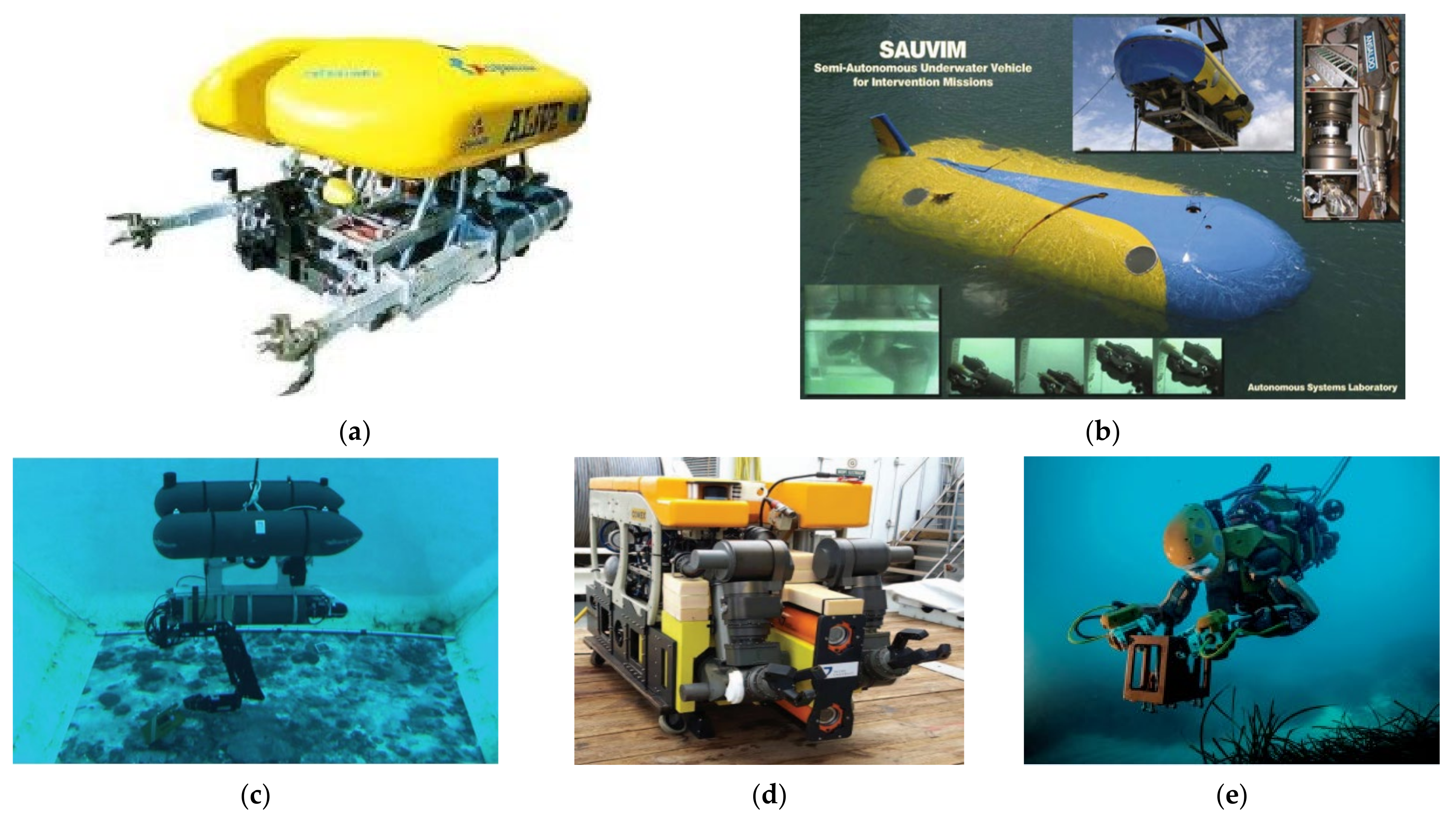
Figure 1. Different kinds of UVMS: (a) ALIVE [11]; (b) SAUVIM [22]; (c) GIRONA 500 [23]; (d) DexROV [19]; (e) Ocean One [20].
Jmse 09 01131 g001
Figure 2. The model of UVMS equipped with a series manipulator and its coordinate frame.
Jmse 09 01131 g002
Figure 3. Layout of thrusters of the vehicle.
Jmse 09 01131 g003
Figure 4. Desired input and actual output of control force/moment.
Jmse 09 01131 g004
Figure 5. The process of grasping an object of end effector: (a) parted; (b) grabbed.
Jmse 09 01131 g005
Figure 6. Schematic diagram of the UVMS control framework.
Jmse 09 01131 g006
Figure 7. The process of grasping an object.
Jmse 09 01131 g007
Figure 8. The position of the vehicle without control.
Jmse 09 01131 g008
Figure 9. The position error of end effector without vehicle control.
Jmse 09 01131 g009
Figure 10. The desired and actual position of end effector with vehicle position control.
Jmse 09 01131 g010
Figure 11. The position tracking error of end effector with vehicle position control.
Jmse 09 01131 g011
Figure 12. The desired and actual position of end effector with vehicle position and attitude control.
Jmse 09 01131 g012
Figure 13. The position tracking error of end effector with vehicle position and attitude control.
Jmse 09 01131 g013
Figure 14. The trajectory of the position of the vehicle and the tip of end effector in vertical plane.
Jmse 09 01131 g014
Figure 15. Vehicle and manipulator responses: (a) vehicle position response in x-direction; (b) vehicle position response in z-direction; (c) vehicle attitude response; (d) joint q1 trajectory responses; (e) joint q2 trajectory responses; (f) joint q3 trajectory responses.
Jmse 09 01131 g015
Figure 16. Vehicle and manipulator errors responses: (a) vehicle position error response in x-direction; (b) vehicle position error response in z-direction; (c) vehicle attitude error response; (d) joint q1 error responses; (e) joint q2 error responses; (f) joint q3 error responses.
Jmse 09 01131 g016
Figure 17. Forces/moments acting on the vehicle: (a) forces; (b) moments.
Jmse 09 01131 g017
Figure 18. Joint torques of the manipulator.
Jmse 09 01131 g018
Figure 19. The RMSE of the vehicle, the manipulator, and end effector.
Jmse 09 01131 g019
Table 1. Physical parameters of the vehicle.
ParametersValuesParametersValues
Length [m]5.3Mass [kg]5454.54
Buoyancy [N]53,400Gravity [N]53,400
Center of buoyancy [m][0,0,0]Center of mass [m][0,0,0.061]
Maximum translational
velocity [m/s]
[0.2,0.2,0.2]Maximum rotational
velocity [rad/s]
[0.2,0.2,0.2]
Maximum control
force [N]
[200,200,400]Maximum control
moment [Nm]
[200,200,200]
Moment of
inertia [kg•m2]
Ixx2038Moment of
inertia [kg•m2]
Ixy−13.58
Iyy13,587Iyz−13.58
Izz13,587Ixz−13.58
Table 2. Main parameters of manipulator with 3-DOF links.
ParametersLink 1Link 2Link 3
Mass [kg]31.420.115.4
qm [rad]q1q2q3
Radius [m]0.10.080.07
Length [m]111
Joint angular velocity [deg/s]202020
Maximum joint torque [Nm]300200150
Viscous friction [Nms]30205
Moment of inertia
[kg•m2]
Ixx1.650.750.4
Iyy116.34
Izz116.34
Table 3. Main parameters of the object.
ParametersValuesParametersValues
Sphere radius [m]0.1Mass [kg]9.21
Buoyancy [N]50.96Gravity [N]90.26
Moment of
inertia [kg•m2]
Ixx0.037Moment of
inertia [kg•m2]
Ixy0
Iyy0.037Iyz0
Izz0.037Ixz0
Table 4. Time process of grasping operation.
NumberTime [s]Action of Manipulator
0~25From initial position to start position
25~40From start position to goal position
40~55From goal position to start position
-55~60Grasping operation
60~75From start position to goal position
75~90From goal position to start position
Publisher’s Note: MDPI stays neutral with regard to jurisdictional claims in published maps and institutional affiliations.