Article

Study on an Analytical Solution to the Mechanical Response of Soil Cut by a Bionic Force Enhancement Grouser

1
College of Civil Engineering and Mechanics, Xiangtan University, Xiangtan 411105, China
2
Hunan Key Laboratory for Computation and Simulation in Science and Engineering, Xiangtan University, Xiangtan 411105, China
3
Institute of Mechanics, Chinese Academy of Sciences, Beijing 100190, China
*
Author to whom correspondence should be addressed.
J. Mar. Sci. Eng. 2021, 9(12), 1401; https://doi.org/10.3390/jmse9121401
Submission received: 12 November 2021 / Revised: 2 December 2021 / Accepted: 3 December 2021 / Published: 8 December 2021
(This article belongs to the Section Ocean Engineering)

Abstract

:
With the depletion of land mineral resources, people have turned their attention to the sea. As an important part of deep-sea mining systems, the technical research and development of ore collectors has always been a difficult problem in many countries. According to the characteristic that buffalo hoof is suitable for walking on soft soil, a kind of bionic grouser for a deep-sea mining vehicle is designed in this paper. Through the optimization of Rankine’s passive earth pressure theory, the formula for calculating the tractive force of the grouser is obtained. The accuracy of the analytical solution is verified by finite element simulation, and the force enhancement mechanism of the bionic grouser is revealed. The results show that the design of the bionic grouser has a significant effect on the improvement of tractive force, and the tractive force of the No. 1 bionic grouser is 17.52% higher than that of the straight grouser. On this basis, the geometric parameters of the bionic grouser profile are optimized. The results show that when L is 0 mm and R is 183 mm, the force enhancement effect reaches the maximum of 27%, which provides a design basis for optimizing the grouser and improving the mining efficiency of the collector.

1. Introduction

With the rapid economic development of countries worldwide, the demand for mineral resources is becoming more and more exuberant, which gradually makes it more and more difficult for land resources to meet the needs of development [1]. To maintain sustained economic growth, people turn their attention to the ocean [2,3]. Marine mineral resources are prosperous, especially submarine metal nodule deposits, which are extremely large, in which rare metal nodule minerals (such as manganese metal nodules) and gas hydrates are extremely abundant [4,5,6], but most of these minerals are distributed on the seafloor below 4000 m. Therefore, mining is challenging [7,8]. The complex deep-sea environment puts higher requirements on the deep-sea mining system. After the successful sea test of “Kunlong 500” developed by the team in the Pacific Ocean, the hydraulic mining system is considered the most balanced commercial mining system [9,10].
As a vital part of the deep-sea mining system, the collector shown in Figure 1 is a critical point. The characteristics required for the regular operation of the collector include the ore collection stability, energy efficiency, durability, maintainability, and controllability [11,12]. The collector’s task is to efficiently walk and mine on the soft seafloor subsoil, collect, clean, and transport the ore to the ore lifting system [13,14], without causing excessive damage to the marine environment. Due to the low shear strength and obvious rheological behavior of deep-sea sediments, it is easy to slip between the grouser so that the traction force of the grouser is reduced, endangering the working efficiency of the collector [15].
In recent years, scientists have done much research on the tractive force of grousers in the process of walking on the soft subsoil. Li et al. [16] studied the tractive force of grousers under different sand content sediments and found that the higher the sand content under the same slip ratio, the greater the tractive force, and the slip rate should be controlled below 6% in order to avoid the decrease of tractive force. Using the traditional Mohr–Coulomb failure criterion and the shear speed of 15 mm/s, Janarthanan et al. [17] carried out experiments and simulations in the deep-sea soft soil environment and studied the influence of different shapes of grouser on the traction force of the collector. Li et al. [18] carried out a large number of experiments on π-shaped, T-shaped, and V-shaped grousers, and found that the traction force of the π-shaped crawler is more sensitive to width and the T-shaped one is more sensitive to height, while the structural parameters of the V-shaped grouser have little influence on it, but it has a minor vertical subsidence displacement. Yang et al. [19,20] derived the horizontal and vertical resistance of the tracked vehicle and used MATLAB to determine the optimal driving resistance by analyzing the vehicle parameters and soil parameters. Based on the constitutive model of the elastic model and the Mohr–Coulomb model, Abaqus was used to simulate the grouser shear soil, and the simulation results were in good agreement with the experimental results. Shin et al. [21] found that the total thrust of the tracked vehicle is slightly lower than the product of the number of single grousers and the number of grousers and carried out a series of track tests using the three-track system. The experimental results showed that the soil thrust of the rear grouser is small due to the shielding effect of the front grouser, while the influence of the rear grouser on the front is negligible.
Bionics is an ancient and young discipline. Animals and plants, in order to adapt to the environment, through millions or even thousands of years of evolution, have structures that are often much more exquisite than human machinery. By studying the mechanism and anatomical structure of biology, scientists apply the developed bionic structure to engineering [22,23,24], medicine [25,26,27], and even computer fields [28], bringing new technological innovations to various industries. Sun [29] created a new type of micro air vehicle by biomimetic design of the origami wings of rhino beetles, which can restore a stable flight state from a flight collision. Wu et al. [30] designed a bionic plate by studying the microstructure of fish scales, and compared it with a smooth plate under the flow of 0.66 m/s, and found that the maximum drag reduction rate reached 2.8%.
The design of the collector grouser is crucial for improving the walking stability and mining efficiency of a collector [31,32], and therefore, improving the common phenomena of skidding and subsidence in the operation of a deep-sea collector. In this paper, the bionic force enhancement design of a collector grouser is studied, which provides a necessary theoretical basis for its optimal design.

2. Derivation of an Analytical Solution

2.1. Bionic Design of the Grouser

Based on the unique shape curve of the buffalo hoof, the characteristics of the grouser that can improve the traction capacity of the collector track are analyzed. Through observation, it can be seen that the shape of the front surface of the buffalo’s rear hoof can make the buffalo walk stably in the soft clay, which is an important reason for the buffalo to gain propulsion. In this study, bionic grousers were designed according to the structural characteristics of the front surface of buffalo hoof entry. Figure 2a shows the apparent morphology of the buffalo hoof, and Figure 2b shows the cross-sectional feature diagram of the bionic grouser. Where L is the distance from the curvature change point to the top of the grouser, and R is the curvature radius of the arc part. The obvious point of curvature change can be observed from the figure, which is an essential factor affecting the propulsion force and walking resistance.

2.2. Hypothetical Conditions for the Derivation of Analytical Solutions

Because the classical Rankine earth pressure theory has a wide range of applications and the calculation process is simple and easy to understand, it has been widely popularized in practical engineering. However, Rankine’s earth pressure theory has very obvious limitations: the first condition of Rankine’s earth pressure theory is to assume that the back of the wall is vertical and smooth and the filling behind the wall is horizontal, but there is often an inclination angle on the back of the wall in practical engineering. This requires us to adopt a new method to optimize Rankine earth pressure.
Now the passive earth pressure calculation model of the bionic grouser is assumed as follows: (1) grousers are rigid and curved; (2) the surface of the deep-sea bottom soil is horizontal, and within the range of mining depth, it is homogeneous; (3) the friction in the direction of grouser thickness is not considered.

2.3. Overall Force Analysis

As shown in Figure 3, with the shearing of the grouser plate, the soil near the grouser is squeezed. According to Rankine’s earth pressure theory, it is considered that the soil is in a Rankine passive earth pressure state in this area, and the soil after the grouser is shearing along the slip plane BC. The normal pressure Fp acting on the grouser is the passive earth pressure, which varies with the volume of the compressed soil on the surface of the grouser. The passive earth pressure of cohesive soil is also composed of another part, that is, the earth pressure Fc caused by cohesion c is positive and does not change with depth.
The traction formula of the grouser is:
F = Fp + Fc,
where the Fp is the passive earth pressure of the grouser, and Fc is:
F c   =   2 c K p , K p = t a n 2 ( π 4 + φ 2 ) ,  
First of all, the compression area of the surface is analyzed, and the value of passive earth pressure Fp of the grouser surface is calculated. At this time, the passive earth pressure, its sliding surface, and its stress diagram are shown in Figure 3:
The closed area where the ABC is located is taken as the isolation unit, and the self-weight of the isolation body under passive earth pressure is as follows:
W = γ b S A B C
where γ is the effective unit weight of deep-sea soil, b is the depth of grouser, and SABC is the area of ABC.
The calculation formula of passive earth pressure is:
F p = 0 H p p ( z ) d z
where pp(z) is the value of earth pressure per unit depth at depth z.

2.4. Force Analysis of the Microelement

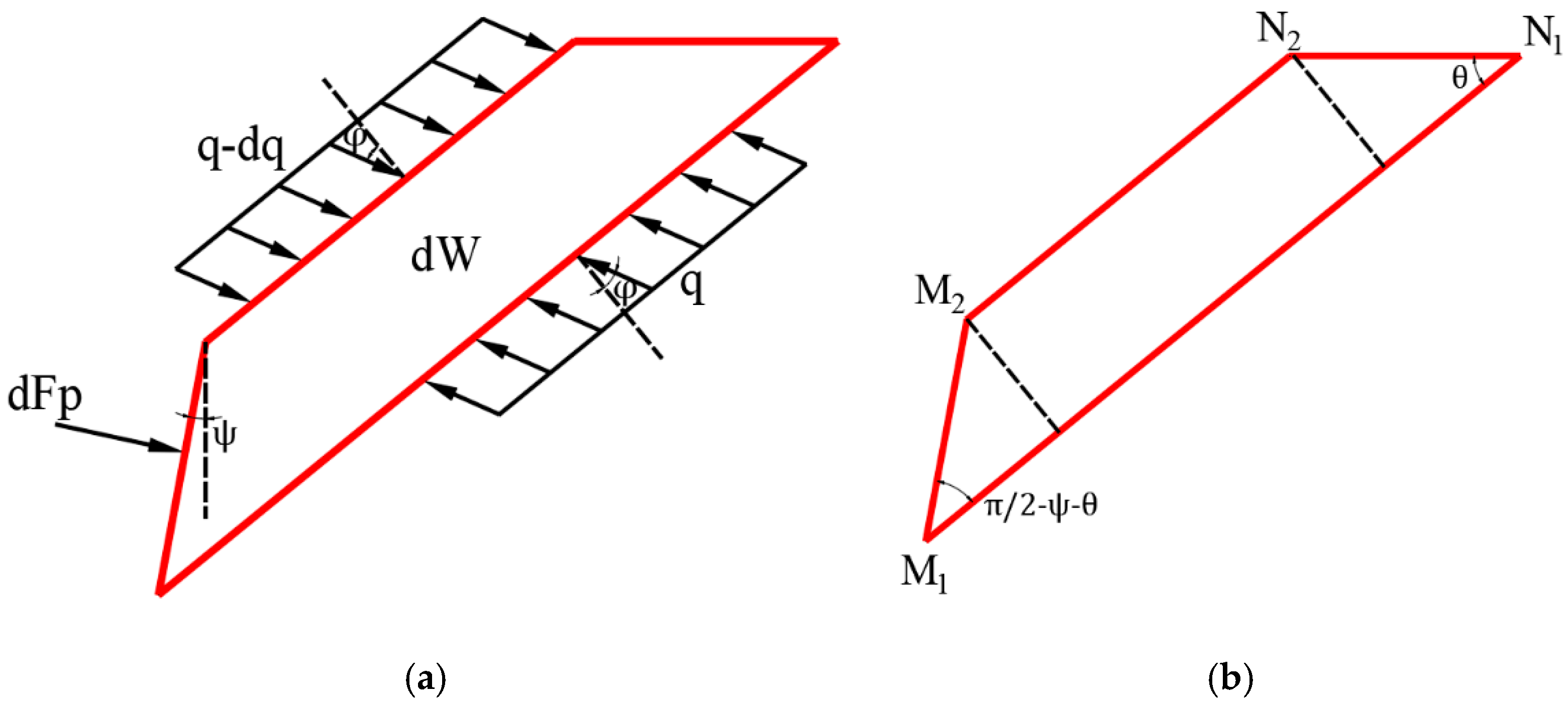
The force acting on the microelement under passive earth pressure is shown in the Figure 4. Macroscopically, the static W, R, and f of the isolator are dW, q, and dFp, and the contact force between soil layers is expressed by the uniformly distributed load q − dq and q of the surface layer of the microelement, as shown in Figure 5.
Firstly, the soil weight dW of the microelement is calculated. dW is related to the M1N1N2M2 area of trapezoidal microelements. The formula for calculating the height of the trapezoid is as follows:
d h = c o s ( θ + ψ ) c o s ψ d z
where θ is the dip angle between the slip surface and horizontal plane, and ψ is the angle between a tangent and the vertical direction of the grouser surface corresponding to microelement dz.
ψ depends on the characteristics of the grouser surface, and its calculation formula is as follows:
ψ = { 0 ; 0 z l arcsin ( z l R ) ; l < z H
The length of the lower bottom edge and the upper bottom edge of the trapezoid is calculated as:
M 1 N 1 = z s i n θ , M 2 N 2 = z s i n θ s i n ( ψ + θ ) + c o s ( ψ + θ ) c o t θ c o s ψ d z
In the joint Formula (5), the trapezoidal area can be expressed as:
S M 1 N 1 N 2 M 2 = 1 2 ( M 1 N 1 + M 2 N 2 ) d h = c o s ( θ + ψ ) s i n θ c o s ψ z d z
Formula (6) can be substituted for (1) to derive the soil weight of the microelement as follows:
d W = γ b S M 1 N 1 N 2 M 2 = c o s ( θ + ψ ) s i n θ c o s ψ b z γ d z
Based on the static analysis of the microelement, the equilibrium equation in the limit equilibrium state is as follows:
{ F x = d F p c o s ψ + ( ( q d q ) M 2 N 2 q M 1 N 1 ) s i n ( θ + φ ) = 0 F y = d F p s i n ψ + ( ( q d q ) M 2 N 2 q M 1 N 1 ) c o s ( θ + φ ) + d W = 0
Eliminate the (qdq) item in the above formula and get:
d F p = d W c o s ψ c o t ( θ + φ ) s i n ψ
Insert Formula (7) into Formula (9) to obtain:
d F p d z = f p ( θ ) b z γ
Among them, the specific expression of fp (θ) is:
f p ( θ ) = c o s ( θ + ψ ) ( c o s ψ c o t ( θ + φ ) s i n ψ ) s i n θ c o s ψ
As a result, the passive earth pressure resultant force Fp of the grouser is expressed in the form of definite integral as follows:
F p = b γ 0 H z c o s ( θ + ψ ) ( c o s ψ c o t ( θ + φ ) s i n ψ ) s i n θ c o s ψ d z
If θ = π 4 φ 2 is taken, and placed in (12), then:
F p = b γ 0 H c o s ( π 4 φ 2 + ψ ) ( c o s ψ s i n ψ ) s i n ( π 4 φ 2 ) c o s ψ z d z
Formula (14) is discretized by the Simpson formula, and the analytical solution of passive earth pressure is obtained as follows:
F = R b γ ( l a r c s i n H l R + 1 2 l ( c o t ( π 4 φ 2 ) 1 ) ( a r c s i n H l R I n | H l R 2 ( H l ) 2 R | ) + R R 2 ( H l ) 2 + ( c o t ( π 4 φ 2 ) 1 ) [ 1 2 ( l H ) 1 4 2 I n | ( 2 ( H l ) R ) ( 2 R 2 ( H l ) 2 R ) ( 2 ( H l ) + R ) ( 2 R 2 ( H l ) 2 + R ) | 1 2 R 2 ( H l ) 2 + 1 4 2 I n ( 1 2 2 + 1 ) + 1 2 ] ) + 1 2 b γ l 2 c o t ( π 4 φ 2 ) + 2 b c H t a n ( π 4 + φ 2 )

2.5. Theoretical Data

By substituting different R and L values in Formula (16), the maximum traction force of the bionic grouser is obtained, and the results are shown in Table 1. As can be seen from the table, with the decrease of R and L, the traction force increases obviously, in which the bionic grouser, with the distance between grouser L of 30 mm and the radius of curvature R of 500 mm, has the highest tractive force. Compared with the straight plate grouser, the tractive force increases by 9.68%, and the force-increasing effect is obvious.

3. Numerical Simulation

3.1. Simulation Model

The finite element model of a grouser cutting deep-sea bottom soil is shown in Figure 6. It is assumed that the grouser is a curved rigid body, and the velocity in the x-direction is applied on the rigid body, and a reference point is set at the upper end of the grouser, in which its traction force is easy to extract. The fixed support is applied to the bottom and left side of the soil, and the upper and right sides are free surfaces. The time length is set to 4 s and the speed to 15 mm/s [14]. Considering that the height of the bionic grouser of the second generation deep-sea collector is 130 mm, the design parameters L and R of the bionic grouser are 30 mm and 500 mm, respectively. This paper studies the traction characteristics of different bionic grousers through the numerical simulation of cutting deep-sea subsoil with different bionic grousers.

3.2. Deep-Sea Soil Model

Through the shear strength test of deep-sea soft subsoil, many researchers, through studies on the physical and mechanical properties of deep-sea subsoil, found that its shear strength increases with the increase of depth and tends to be stable after a certain depth. It has been shown that the thin and soft subsoil has the bearing capacity to make the collector walk freely. The rate-dependent characteristics of deep-sea bottom soil mean that the deep-sea bottom soil shows different mechanical properties when the grouser of the collector travel at different speeds. According to the physical and mechanical properties of deep-sea bottom soil, scholars at home and abroad continue to study and improve it, in which many researchers use the extended Drucker–Prager model to simulate the soil cutting process [33,34,35]. However, few researchers have considered the rate-dependent characteristics of deep-sea subsoil. In this paper, deep-sea subsoil’s rate-dependent characteristics are studied, the rate-dependent parameters in the finite element software are calibrated with triaxial compression experiments, and the rate-dependent extended Drucker–Prager constitutive model is obtained. The soil parameters and rate-related parameters are shown in Table 2 and Table 3.

3.3. Numerical Simulation Data

The force-increasing performance of a bionic grouser was studied by simulating a straight plate grouser and bionic grouser in the soil under the same conditions. The simulation results are shown in Table 4. Compared with straight plate grousers, bionic grousers have a greater traction force. The maximum traction force of a bionic grouser with a grouser tip distance L of 30 mm and curvature radius R of 500 mm is 17.52% higher than that of a straight plate grouser, which has a significant force-increasing effect.

4. Results

4.1. Effect of L on the Tractive Force of a Grouser

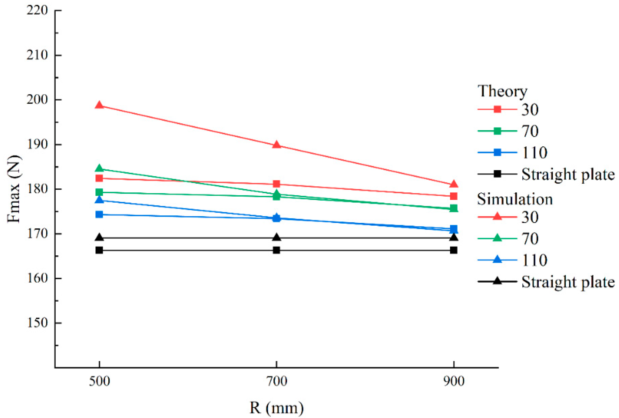
As can be seen from Figure 7, the grouser traction force increases with the decrease in grouser tip distance L. This is because the grouser is composed of a straight plate part with a grouser tip distance L and a curved surface part with a curvature radius of R, and the grouser height is fixed, so when the grouser tip distance L decreases, the soil volume in the compression area increases. The length of the sliding surface of the soil also increases, and, when it is sheared, the sliding resistance of the soil and the traction provided to the grouser is greater.

4.2. Effect of R on the Tractive Force of the Grouser

Figure 8 shows the relationship between the radius of curvature R of the curved part of the grouser and the maximum traction force Fmax under different grouser tip distance L. As can be seen from the figure, Fmax increases with the decrease of R. This is because when the grouser walks on the simulated soil, the bionic curved surface of the grouser shears the soil in the compression area. On the one hand, with the decrease of the radius of curvature and the distance from the top of the grouser, the volume of the soil in the slip zone increases, and the greater the tractive force provided by the soil to the grouser; on the other hand, because of the curvature part of the grouser in the process of walking, the soil in the slip zone produces vertical component force upward and forward horizontal component force, while the vertical component makes the soil in the slip zone denser, thus increasing the soil shear strength and increasing the grouser traction force.
In addition, it is obvious that the simulation results are slightly higher than the experimental results, but both are within the allowable fault tolerance range. The possible reason for this phenomenon is that the soil accumulation effect is considered in the numerical simulation. With the advance of the grouser, more and more soil accumulates, the resistance of the grouser becomes greater and greater, and the corresponding traction force is also greater.

4.3. Accuracy Verification of the Analytical Solution

By comparing the maximum traction force of the grouser with the same profile parameters in Figure 7 and Figure 8, it is found that the grouser parameters of the maximum traction force are the same, in which the value of the analytical solution is 182.4 N, and that of the numerical simulation is 198.694 N. Furthermore, the maximum and minimum errors of the maximum traction force measured by the analytical solution and the finite element method are 8.2% and 0.1%, respectively, and the average error is 2.132%, which shows that the derivation of the analytical solution has high calculation accuracy.

4.4. Force Enhancement Mechanism of the Bionic Grouser Cutting Deep-Sea Soil

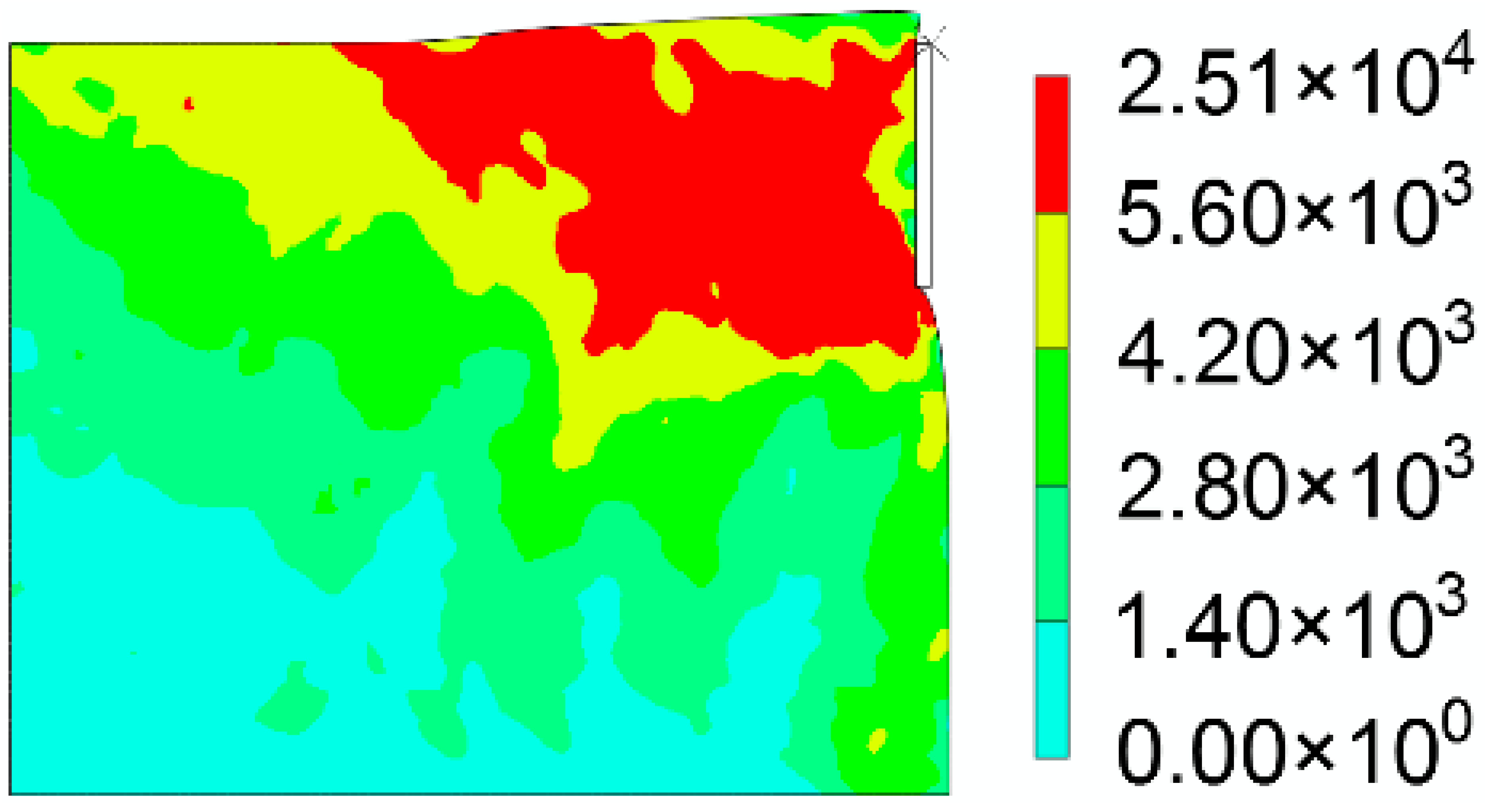
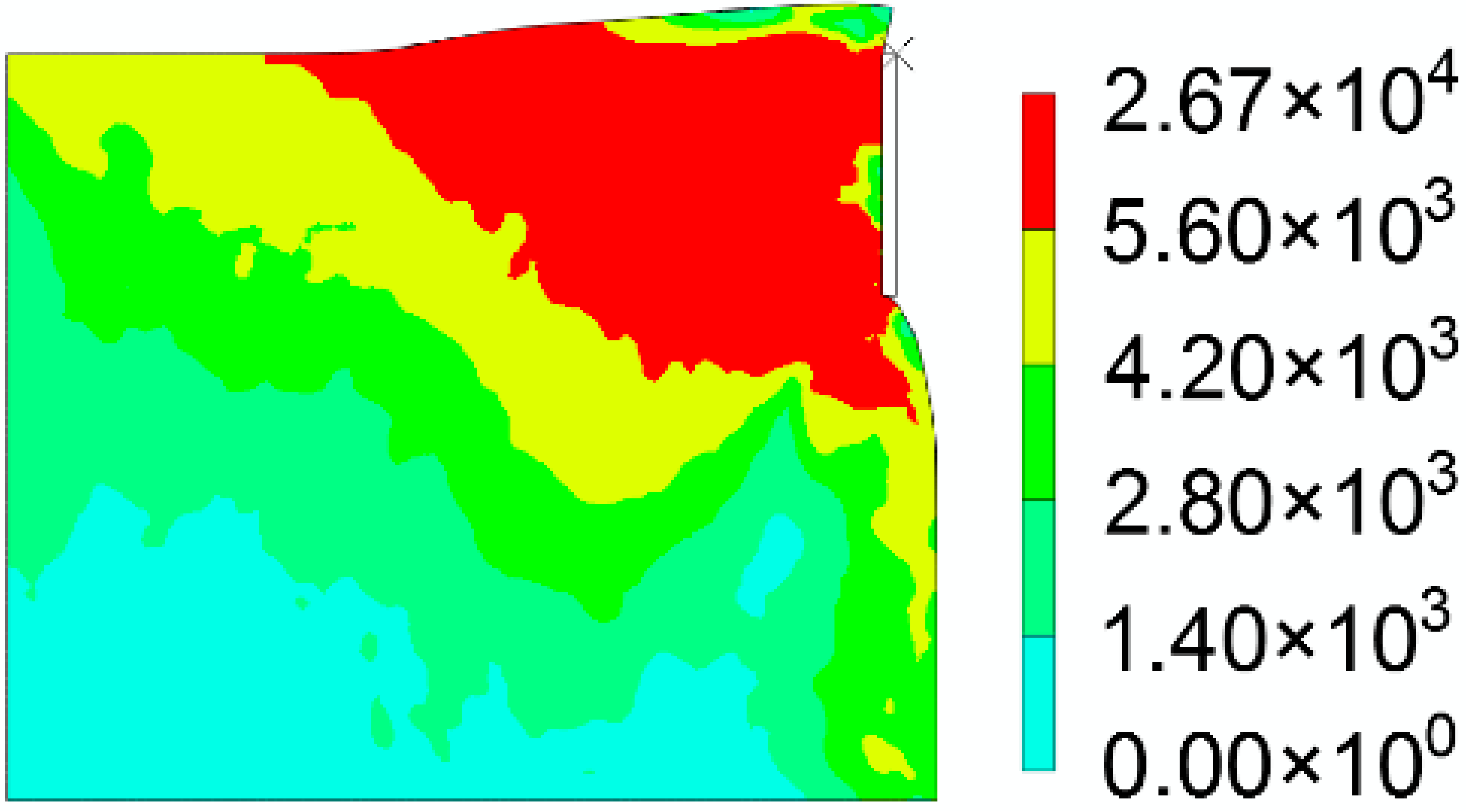
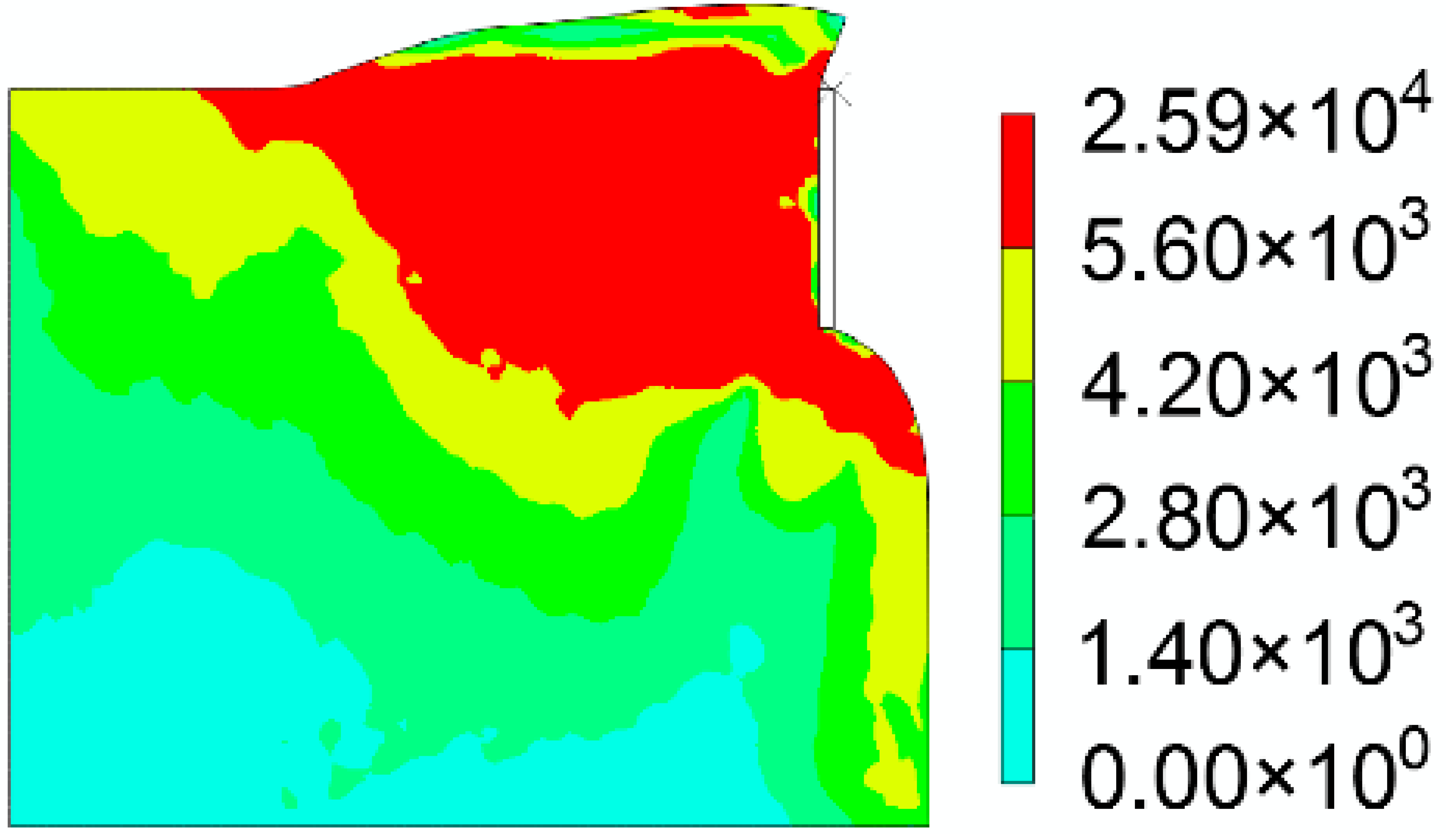
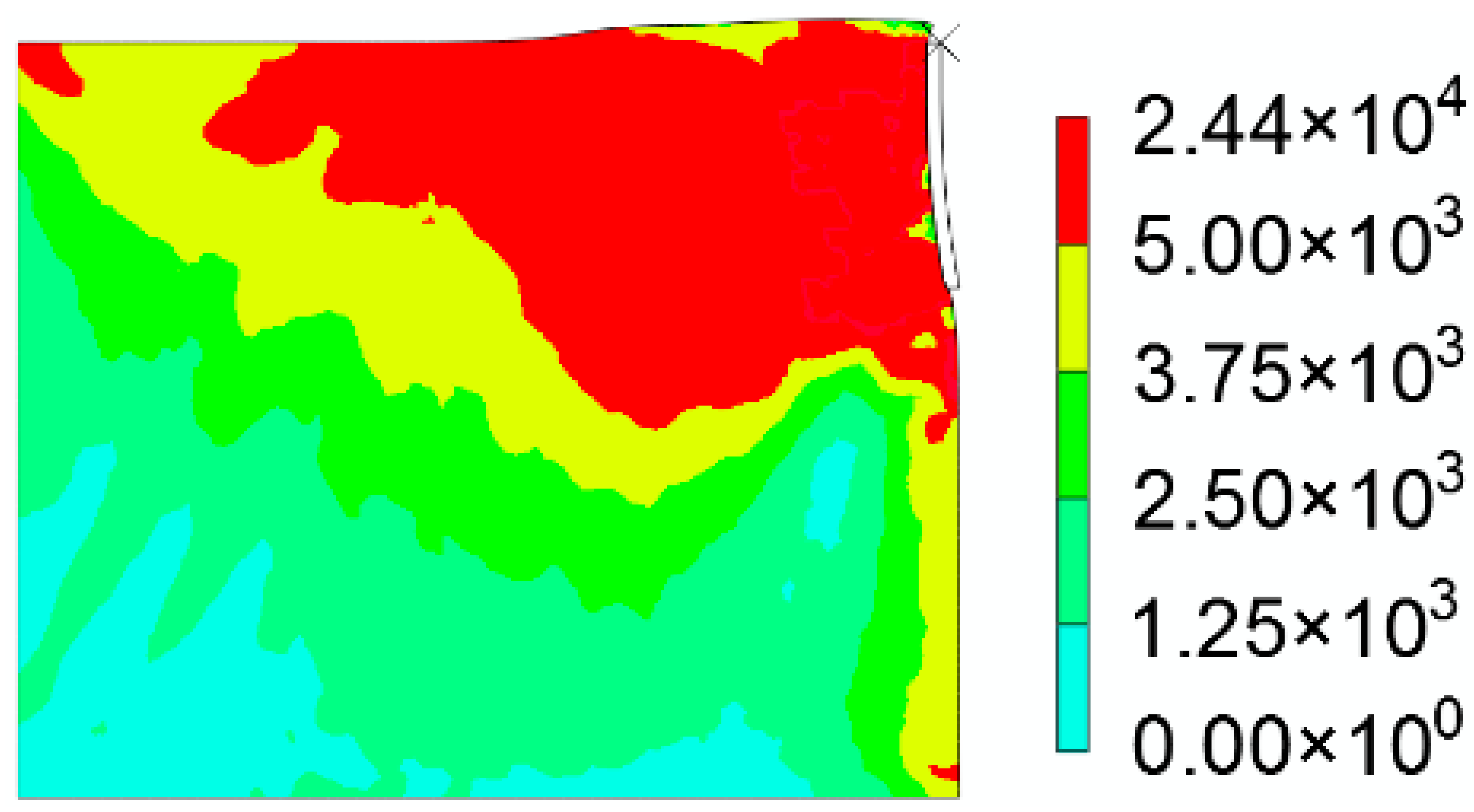
As shown in Table 5, to study the force enhancement mechanism of the bionic grouser in cutting deep-sea bottom soil, the straight plate grouser and No. 1 bionic grouser (L = 30 mm, R = 500 mm) were selected for finite element cutting simulation, and the soil stress cloud diagrams at 1.2 s, 2 s and 4 s were obtained.
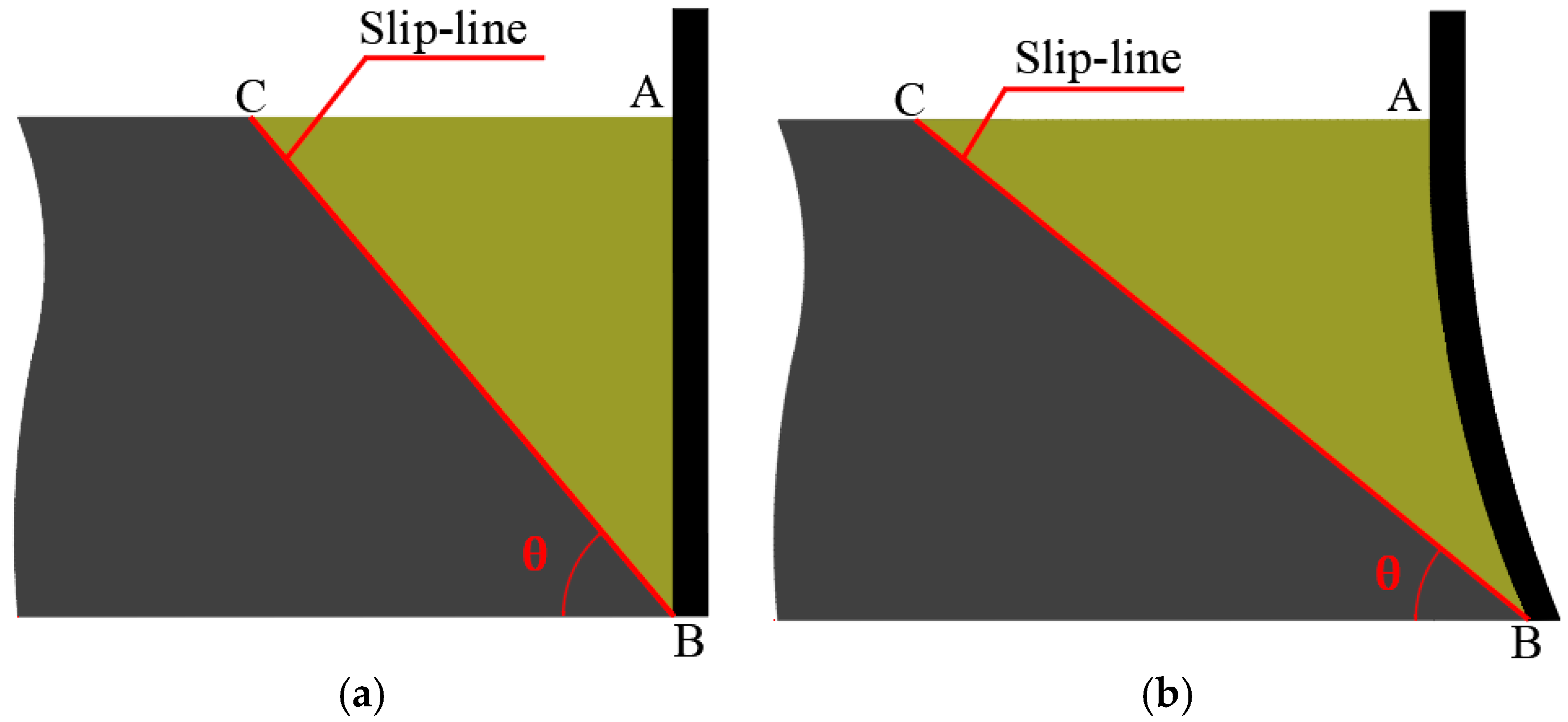
In the process of cutting deep-sea bottom soil with a grouser, the slip zone in front of the grouser is formed as shown by ABC in Figure 9, and the plastic deformation of this part of the soil is larger, which is shown in dark color in the cloud image. From the comparison of the cloud images of the straight plate grouser and bionic grouser in Table 5, it can be clearly seen that the plastic deformation region of the bionic grouser is larger. That is, the soil volume in the slip zone increases, and the length of the soil slip line also increases. When the soil is sheared, the sliding resistance is more excellent, and the traction force provided to the grouser is greater.
On the other hand, when the distance from the top of the grouser L decreases, the B point extends in the opposite direction of movement, and the soil directly below the AB curve will increase the upward vertical component when the grouser is shearing, resulting in a compaction effect between the grouser and the soil, resulting in greater friction between the soil and the grouser, thus increasing the tractive force of the grouser.

4.5. Force Enhancement Design of the Bionic Grouser

The previous data shows that the maximum traction force Fmax of the bionic grouser has apparent regularity with grouser tip distance L and curvature radius R. To explore this law, we used the Mesh function of MATLAB to make a three-dimensional image of the analytical solution. It can be seen from Figure 10 that the traction force increases with the decrease in grouser tip distance L and curvature radius R, and when L is 0 mm and R is 183 mm, the maximum traction force reaches the optimal value of 211.2 N, which increases by 27.0% compared with 166.3 N of straight grouser, and the force-increasing effect is significant.

5. Conclusions

According to the bionic structure of buffalo hoof, taking the distance L from the top of the bionic grouser to the point of curvature change and the radius of bionic curvature R as parameters, the influence equation of traction force on the bionic grouser profile parameters is established by optimizing Rankine earth pressure theory. The analytical solution of track parameters under the action of maximum traction force is obtained. The process of cutting deep-sea bottom soil with a grouser with different grouser profile parameters is studied by numerical simulation. The simulation results are close to the analytical solution, and the force-increasing mechanism of the bionic grouser is analyzed combined with the displacement cloud map. The correctness of the analytical solution is further verified. According to the three-dimensional variation curve of the grouser profile parameters and the maximum traction force, we found that the maximum traction force of the bionic grouser increases with the decrease of the distance between the grouser and the radius of curvature. The reasonable selection of grouser profile parameters (L = 0 mm, R = 183 mm) can effectively improve the tractive force of the grouser, provide theoretical support for the deep-sea collector’s grouser design, and significantly improve the mining efficiency.
The future work will focus on the derivation of the new analytical solution, which will consider the asymptotic slip line and the soil arch effect and be verified by experiments.

Author Contributions

Conceptualization and methodology, W.M., Y.C., W.Z. and W.Q.; software, Y.C. and W.M.; validation, Y.C. and W.Z.; investigation, Y.C. and W.Q.; resources, W.M. and W.Z.; theoretical derivation, Y.C. and W.Z.; data curation, Y.C. and W.M.; writing—original draft preparation, W.M., Y.C. and W.Q.; writing—review and editing, W.M., Y.C. and W.Q.; supervision W.M. and Y.C.; project administration, W.M. and W.Z. All authors have read and agreed to the published version of the manuscript.

Funding

This research was funded by the National Natural Science Foundation of China (NSFC No.12072309), the Education Department Foundation of Hunan Province (19B546), the Hunan Innovative Province Construction Project (2019RS1059).

Institutional Review Board Statement

Not applicable.

Informed Consent Statement

Not applicable.

Data Availability Statement

The data presented in this study are available on request from the corresponding author.

Acknowledgments

The authors want to give their sincere gratitude to Cong Hu for his kind help on derivation the equations in this paper. We also sincerely thank Qing Cai for her help on the finite element simulation in this paper. The author would also like to thank “Engineering Research Center of Rock-Soil Drilling & Excavation and Protection, Ministry of Education” for their help in this article.

Conflicts of Interest

The authors declare no conflict of interest.

References

  1. Mudakkar, S.R.; Zaman, K.; Khan, M.M.; Ahmad, M. Energy for economic growth, industrialization, environment and natural resources: Living with just enough, Renew. Sust. Energ. Rev. 2013, 25, 580–595. [Google Scholar] [CrossRef]
  2. Leal Filho, W.; Abubakar, I.R.; Nunes, C.; Platje, J.; Ozuyar, P.G.; Will, M.; Nagy, G.J.; Al-Amin, A.Q.; Hunt, J.D.; Li, C. Deep Seabed Mining: A Note on Some Potentials and Risks to the Sustainable Mineral Extraction from the Oceans. J. Mar. Sci. Eng. 2021, 9, 521. [Google Scholar] [CrossRef]
  3. Chung, J.S. Deep-ocean Mining Technology: Learning Curve I. In Proceedings of the 5th Ocean Mining Symposium, Tsukuba, Japan, 15 September 2003; pp. 1–6. [Google Scholar]
  4. Bondarenko, V.; Sai, K.; Prokopenko, K.; Zhuravlov, D. Thermodynamic and geomechanical processes research in the development of gas hydrate deposits in the conditions of the Black Sea. Min. Miner. Depos. 2018, 12, 104–115. [Google Scholar] [CrossRef]
  5. Bazaluk, O.; Sai, K.; Lozynskyi, V.; Petlovanyi, M.; Saik, P. Research into Dissociation Zones of Gas Hydrate Deposits with a Heterogeneous Structure in the Black Sea. Energies 2021, 14, 1345. [Google Scholar] [CrossRef]
  6. Kobolev, V. Structural, tectonic and fluid-dynamic aspects of deep degassing of the Black Sea megatrench. Min. Miner. Depos. 2017, 11, 31–49. [Google Scholar] [CrossRef] [Green Version]
  7. Dai, Y.; Ma, F.Y.; Zhu, X.; Liu, H.; Huang, Z.H.; Xie, Y. Mechanical Tests and Numerical Simulations for Mining Seafloor Massive Sulfides. J. Mar. Sci. Eng. 2019, 7, 252. [Google Scholar] [CrossRef] [Green Version]
  8. Hong, S.; Kim, H.W.; Yeu, T.; Choi, J.S.; Lee, T.H.; Lee, J.K. Technologies for Safe and Sustainable Mining of Deep-Seabed Minerals. In Environmental Issues of Deep-Sea Mining; Springer: Cham, Switzerland, 2019. [Google Scholar] [CrossRef]
  9. Bath, A.R.; Preussag, A.G. Deep Sea Mining Technology: Recent Developments and Future Projects. In Proceedings of the Offshore Technology Conference, Houston, TX, USA, 1 May 1989; pp. 333–340. [Google Scholar]
  10. Lecourt, E.J., Jr.; Williams, D.W. Deep ocean mining-new application for oil field and marine equipment. In Proceedings of the Offshore Technology Conference, Houston, TX, USA, 18 April 1971. [Google Scholar]
  11. Chung, J.S. Deep-Ocean Mining Issues and Ocean Mining Working Group. In Proceedings of the Third ISOPE Ocean Mining Symposium. International Society of Offshore and Polar Engineers, Goa, India, 8–11 November 1999. [Google Scholar]
  12. Masuda, C.M.J.; Mero, J.L. Continuous bucket line dredging at 1200ft. In Proceedings of the Offshore Technology Conference, Houston, TX, USA, 18 April 1971. [Google Scholar]
  13. Leng, D.X.; Shao, S.; Xie, Y.C.; Wang, H.H.; Liu, G.J. A brief review of recent progress on deep sea mining vehicle. Ocean. Eng. 2021, 228, 108565. [Google Scholar] [CrossRef]
  14. Chen, W.; Xu, H.L.; Peng, N.; Yang, F.Q.; Lin, P. Linkage characteristics of deep-sea mining lifting system. Ocean. Eng. 2021, 233, 109074. [Google Scholar] [CrossRef]
  15. Zhu, W.; Pan, J.X.; Ma, W.B.; Deng, S.; Zhou, W.J.; Liu, W.Y.; Long, S.G.; Yang, C.Q.; You, L.Y. Dynamic response of the heterogeneous deep-sea sediment with non-linear gradient modulus to mining machine loading. Mar. Georesour. Geotec. 2021. [Google Scholar] [CrossRef]
  16. Li, Y.; He, D.; Si, Q. Theoretical and experimental analysis on the interaction properties between tracks and sediments considering sand content for unmanned underwater tracked bulldozer. Bull. Pol. Acad. Sci. Tech. Sci. 2021, 69, 1–13. [Google Scholar] [CrossRef]
  17. Janarthanan, C.; Gopkumar, K.; Sundaramoorthi, V.; Ramesh, N.R.; Ramadass, G.A. Influence of Grouser Geometrical Parameters of Deep-Sea Crawler Vehicle on Soft Clays. In Proceedings of the Fourth International Conference in Ocean Engineering (ICOE2018); Lecture Notes in Civil Engineering; Murali, K., Sriram, V., Samad, A., Saha, N., Eds.; Springer: Singapore, 2019; Volume 22. [Google Scholar] [CrossRef]
  18. Li, Y.; He, D.C.; Si, Q.R.; Meng, X.P. Effect of track shoes structural parameters on traction performance of unmanned underwater tracked bulldozer. Ocean. Eng. 2021, 237, 109655. [Google Scholar] [CrossRef]
  19. Yang, C.B.; Gu, L.; Lv, W.W. Study of Factors with Effects on Tracked Vehicle Driving Resistance Basis of Bekker Theory. Appl. Mech. Mater. 2013, 288, 80–83. [Google Scholar] [CrossRef]
  20. Yang, C.B.; Gu, L.; Li, Q. Finite element simulation of Track shoe and Ground adhesion. Appl. Mech. Mater. 2014, 644–650, 402–405. [Google Scholar] [CrossRef]
  21. Shin, G.B.; Baek, S.H.; Park, K.H.; Chung, C.K. Investigation of the soil thrust interference effect for tracked unmanned ground vehicles (UGVs) using model track tests. J. Terramech. 2020, 91, 117–127. [Google Scholar] [CrossRef]
  22. Liu, H.R.; Lu, Y.M.; Wang, X.F.; Li, Y.Y.; Yan, Y.Q.; Lai, X.D. Investigation of the effects of the vane blades on the CAP1400 nuclear coolant pump’s performance based on a bionic strategy. Nucl. Eng. Des. 2021, 384, 111465. [Google Scholar] [CrossRef]
  23. Tong, J.; Xu, S.; Chen, D.H.; Li, M. Design of a Bionic Blade for Vegetable Chopper. J. Bionic. Eng. 2017, 14, 163–171. [Google Scholar] [CrossRef]
  24. Huang, H.; Zhang, Y.; Ren, L.Q. Particle Erosion Resistance of Bionic Samples Inspired from Skin Structure of Desert Lizard, Laudakin stoliczkana. J. Bionic. Eng. 2012, 9, 465–469. [Google Scholar] [CrossRef]
  25. Hopkin, M. Bionic brains become a reality. Nature 2006. [Google Scholar] [CrossRef]
  26. Bionic plant can sense explosives. Nature 2016, 539, 8. [CrossRef] [Green Version]
  27. Gu, L.; Poddar, S.; Lin, Y.; Long, Z.; Zhang, D.; Zhang, Q.; Shu, L.; Qiu, X.; Kam, M.; Javey, A.; et al. A biomimetic eye with a hemispherical perovskite nanowire array retina. Nature 2020, 581, 278–282. [Google Scholar] [CrossRef]
  28. Ball, P. Computer engineering: Feeling the heat. Nature 2012, 492, 174–176. [Google Scholar] [CrossRef] [PubMed]
  29. Sun, J. Miniaturization of robots that fly on beetles’ wings. Science 2020, 370, 1165. [Google Scholar] [CrossRef] [PubMed]
  30. Wu, L.; Jiao, Z.; Song, Y.; Liu, C.; Wang, H.; Yan, Y. Experimental investigations on drag-reduction characteristics of bionic surface with water-trapping microstructures of fish scales. Sci. Rep. 2018, 8, 12186. [Google Scholar] [CrossRef]
  31. Yeu, T.K.; Park, S.J.; Hong, S.; Kim, H.W.; Choi, J.S. Path tracking using vector pursuit algorithm for tracked vehicles driving on the soft cohesive soil. In Proceedings of the SICE-ICASE International Joint Conference, Busan, Korea, 18–21 October 2006; pp. 2781–2786. [Google Scholar]
  32. Dai, Y.; Li, X.Y.; Yin, W.W.; Pang, L.P.; Xie, Y.; Huang, Z.H. Dynamic modelling and motion control research on deep seabed miner. Mar. Georesour. Geotec. 2021, 39, 389–397. [Google Scholar] [CrossRef]
  33. Cai, Q.; Ma, W.B.; Rao, Q.H.; Li, G.X. Optimization designof bionic grousers for the crawled mineral collector based on the deep-sea sediment. Mar. Georesour. Geotec. 2020, 38, 48–56. [Google Scholar] [CrossRef]
  34. Asaad, F.; Akbar, A.J.; Amir, M.A. EPR-based material modelling of soils considering volume changes. Comput. Geosci. 2012, 48, 73–85. [Google Scholar] [CrossRef]
  35. Gao, F.P.; Wang, N.; Zhao, B. Ultimate bearing capacity of a pipeline on clayey soils: Slip-line field solution and FEM simulation. Ocean. Eng. 2013, 73, 159–167. [Google Scholar] [CrossRef] [Green Version]
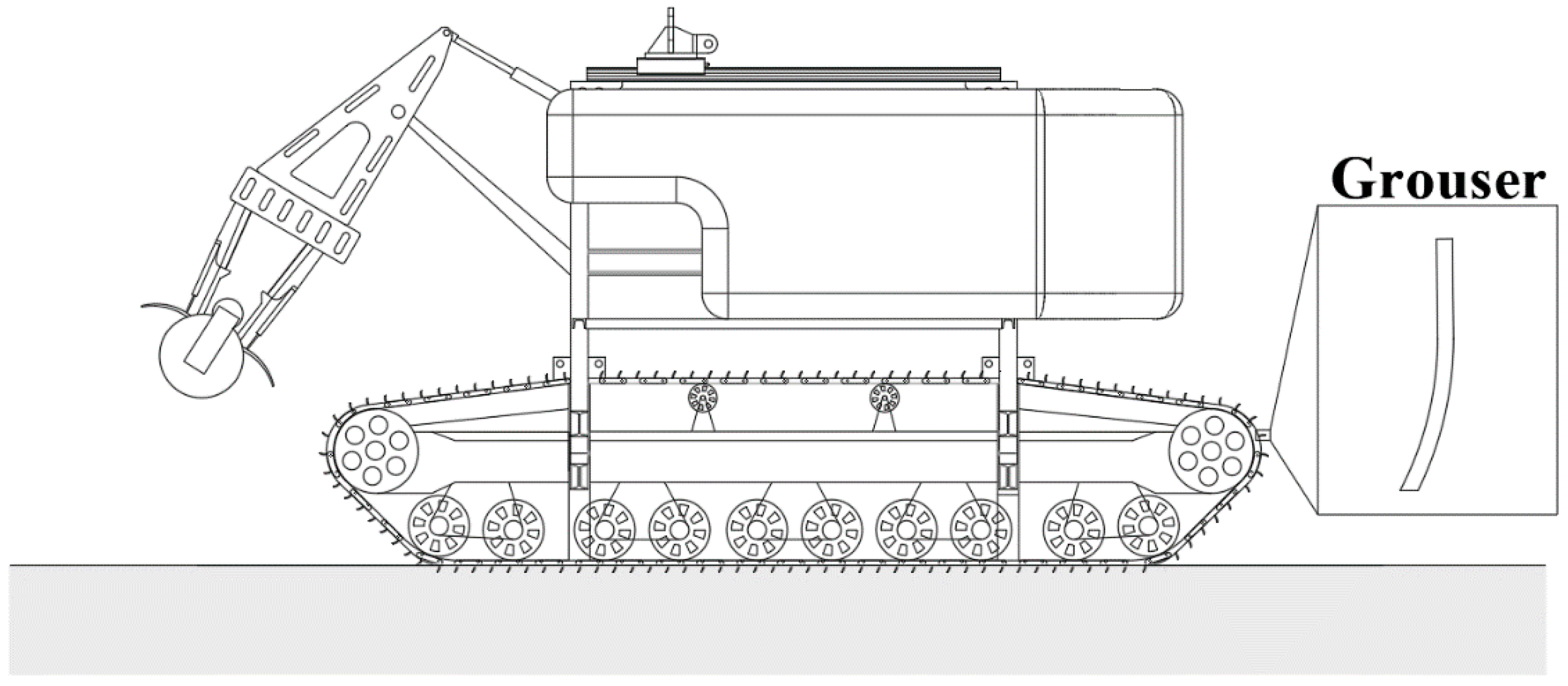
Figure 1. Schematic diagram of a deep-sea mining machine.
Jmse 09 01401 g001
Figure 2. Bionic design of the grouser: (a) Apparent morphology of a buffalo hoof; (b) Cross-sectional feature diagram of the bionic grouser.
Jmse 09 01401 g002
Figure 3. Stress diagram of the slip surface under passive earth pressure.
Jmse 09 01401 g003
Figure 4. Schematic diagram of the microelement division of the isolator.
Jmse 09 01401 g004
Figure 5. Microelement calculation model: (a) Schematic diagram of force acting on microelements; (b) Geometric relation.
Jmse 09 01401 g005
Figure 6. Schematic diagram of the finite element model of deep-sea sediment soil in grouser cutting.
Jmse 09 01401 g006
Figure 7. The influence of grouser tip distance L on the maximum traction force.
Jmse 09 01401 g007
Figure 8. The influence of curvature radius R on the maximum traction force.
Jmse 09 01401 g008
Figure 9. Comparison of slip soil blocks ABC between the straight plate grouser and bionic grouser: (a) Straight Plate Grouser; (b) Bionic Grouser.
Jmse 09 01401 g009
Figure 10. Three-dimensional diagram of the influence of grouser parameters on traction.
Jmse 09 01401 g010
Table 1. Theoretical data of grousers with different shapes.
No.LRFmax
(Theory)
Fmax
(Straight Plate)
Percentage
Increased (%)
130500182.4166.39.68%
230700181.18.90%
330900178.47.28%
470500179.37.82%
570700178.37.22%
670900175.75.65%
7110500174.34.81%
8110700173.44.27%
9110900171.12.89%
Table 2. Basic physical and mechanical parameters of simulated soil.
ParametersE (MPa)νρ/(kg/m3)C/(kPa)φ/(°)kβ/(°)ψ/(°)ω (%)τ (kPa)
Value2.5580.351.315 × 10−66.21.720.983.470165.62
Table 3. Yield stresses and plastic strain rate values.
Yield Stress Ratio (R) Plastic   Strain   Rate   ( ε ˙ p )
10.00
2.970.03
4.020.05
4.330.07
Table 4. Simulated data of grousers with different shapes.
No.LRFmax
(Simulation)
Fmax
(Straight Plate)
Percentage
Increased (%)
130500198.694169.0717.52
230700189.81712.27
330900180.9897.05
470500184.5139.13
570700178.8615.79
670900175.4383.77
7110500177.4884.98
8110700173.5692.66
9110900170.6630.94
Table 5. Simulation stress cloud diagram of different grouser profiles (Pa).
Time (s)1.22.04.0
Straight Plate Grouser Jmse 09 01401 i001 Jmse 09 01401 i002 Jmse 09 01401 i003
No. 1 Bionic Grouser Jmse 09 01401 i004 Jmse 09 01401 i005 Jmse 09 01401 i006
Publisher’s Note: MDPI stays neutral with regard to jurisdictional claims in published maps and institutional affiliations.