Article

Static Characteristics and Leakage Rates of Smooth Annular Seals Based on a New Solution Method for Gas-Liquid Two-Phase Conditions

1
State-Province Joint Engineering Lab of Fluid Transmission System Technology, Zhejiang Sci-Tech University, Hangzhou 310018, China
2
Zhejiang Keer Pump Co., Ltd., Rui’an 325206, China
3
Zhejiang Institute of Mechanical & Electrical Engineering Co., Ltd., Hangzhou 310000, China
*
Author to whom correspondence should be addressed.
J. Mar. Sci. Eng. 2021, 9(5), 523; https://doi.org/10.3390/jmse9050523
Submission received: 27 March 2021 / Revised: 4 May 2021 / Accepted: 9 May 2021 / Published: 12 May 2021
(This article belongs to the Section Ocean Engineering)

Abstract

:
This paper proposes a new solution method for the leakage and static characteristics of smooth annular seal under a homogeneous gas-liquid two-phase flow based on a bulk-flow model. In this solution method, the Rayleigh–Plesset equation is introduced into the governing equations to describe the behavior of bubbles considering mixture compressibility. Detailed comparisons between Childs’ experimental leakage rates and predicted ones based on the proposed method are conducted, and the predicted results show good agreement with the experimental results, with a maximum error of 11.2%. Moreover, static characteristics of the seal, including leakage rates, gas volume fraction (GVF) distribution, pressure distribution, mixture density, and viscosity within the seals, are investigated based on the present method. The results show that as the inlet gas volume fraction increases from 0% to 10%, the local gas volume fraction of each axial position will increase, however, the seal leakage, mixture density, and mixture viscosity will decrease. Bubble radius has little effect on the leakage rates and the static characteristics of the seals. Additionally, comparisons between the characteristics of the model seals with different clearances show that the leakages of the seals with bigger clearance behave more sensitively to the inlet GVF changes.

1. Introduction

Centrifugal pumps are widely used for fluid transportation in marine engineering, aerospace field, and nuclear power plants. In these pumps, annular seals are primarily used to restrict the leakage within the stages, and thereby to reduce the inner flow loss. With the development of ocean exploration and deep-sea engineering, the exploration on the performance of marine centrifugal pumps and the components of pumps such as annular seals has become a hot topic. There are mainly three types of annular seals used in marine centrifugal pumps, i.e., plain annular seals, labyrinth seals, and damping seals. Among the three types, labyrinth seals are mainly used in the operating conditions with high pressure differences. However, with the accumulation of working hours, the wear of labyrinth teeth will cause leakage fluctuation and unstable dynamic characteristics, and then lead to the instability of the rotor system. Although the damping seals could significantly raise the stability of the rotor system, these seals are difficult and expensive to manufacture. Thus, plain seals are the most widely used annular seals in marine pumps for the advantages of stable sealing and dynamic characteristics, low cost, and easy to manufacture. Since the 1970s, scholars and engineers began to explore the methods for accurately predicting the leakage and equivalent dynamic characteristics of annular seals. Black and Jessen [1,2,3,4] investigated the inner flow characteristics within the annular smooth-centered seal of a centrifugal pump and proposed a linear calculation model for the fluid force within the seal clearance. Allaire et al. [5] improved the model and applied it to short plain seals with large eccentricities. This model considered the surface roughness effects and could precisely predict the damping increase of the seal due to leakage flow changes, which provided a theoretical basis for the following prediction models. In the 1980s, Hirs [6,7] proposed the bulk-flow model based on Blasius’ research on pressure flow within pipes under different pressure gradients [8], Davis and White’s research on pressure flow between two parallel surfaces [9], and Couette’s [10] research on the fluid flow between two concentric cylindrical surfaces under drag flow. Subsequently, based on Hirs’ bulk-flow model, Childs [11,12,13] successively proposed the short-seal solution, finite-length solution, and long-seal solution for predicting the dynamic characteristic coefficients of annular seal with different L/D ratios. Among the above three solutions, the finite-length solution, which has considered the factors like inertial terms and inlet swirl, obtains well-matched calculation results with the experimental ones and has become the most widely used calculation method in engineering. Nelson [14] derived the governing equations for compressible fluid in a tapered annular seal based on Hirs’ bulk-flow model. The calculation results indicated that the pre-rotation around the seal inlet would significantly improve the cross-coupled stiffness, and the leakage flow rates would increase as the taper angle increased. Besides, Nelson [15] compared the predicted dynamic characteristics based on different friction models and the comparisons showed that, for rough seals, stiffness coefficients based on Moody’s model were much bigger, while the damping coefficients were smaller than those predicted based on Blasius’ model.
Though there has been abundant research on the bulk-flow method for smooth annular seals, research on the characteristics of seals under two-phase conditions is relatively rare. However, when transporting easily vaporized fluids, centrifugal pumps always work under gas-liquid two-phase operating conditions, which will significantly affect the leakage and rotor-dynamic characteristics of the seals, and then affect the overall efficiency and reliability of the pump. Thus, recently, the sealing and dynamic performance research of the seals operating under gas-liquid conditions have gradually become hot spots, as the two-phase application occasions increase. Beatty and Hughes [16] presented a model for the steady, adiabatic, and turbulent two-phase flow within concentric annular seals. In this model, the fluid was assumed to be a homogeneous mixture of liquid and vapor in thermodynamic equilibrium. The interstage seal of a Space Shuttle Main Engine (SSME) High-Pressure Oxidizer Turbo-Pump (HPOTP) was taken as a numerical example and the numerical results showed that the seal leakage would decrease with the increases of the rotational speed, seal length, and the vapor production. Besides, subcooling before the seal inlet would reduce the vapor production, thereby increasing the seal leakage. Arauz and San Andrés [17,18] presented a “continuous vaporization” bulk-flow model for cryogenic fluid damper seals operating close to the liquid-vapor region, and this model was applicable to all-liquid, liquid-vapor, and all-vapor flow patterns within annular seals. The predicted static seal characteristics, leakage rates, and axial pressure differences based on this model all agreed well with published data for a gaseous nitrogen seal and a liquid nitrogen seal with two-phase flow. Moreover, the dramatic compressibility change within a short distance when a phase change occurred would cause the direct stiffness to increase but the cross-coupled stiffness to decrease [19]. Iwatsubo and Nishino [20] also observed this phenomenon through experiments of an annular seal working with a mixture of low gaseous mass content. Arghir [21] developed a homogeneous-mixture bulk-flow model for annular seal with a textured stator surface and solved the local gas volume fraction by a simplified form of the Rayleigh–Plesset equation, i.e., P = PB, which was developed by Diaz [22] and Alehossein [23]. The changes of the direct damping, direct stiffness, and other coefficients with gas volume fraction were investigated with the developed model. San Andrés [24] developed a bulk-flow model for rotor-dynamic characteristic predictions of two-phase (liquid-gas) annular damper seals. From the calculation results, it was obtained that the leakage flow rates, power loss, and damping coefficients steadily decreased with the increasing gas volume fraction. However, when the inlet GVF = 0 (pure liquid), the dynamic stiffness would decrease as the frequency increases due to the large added fluid mass. Meng [25] systematically investigated the cavitation suction effects of mechanical face seals through experimental and numerical methods. The results found that the main factor inducing suction effects was the low pressure in the cavitation zone, and zero leakage could be achieved by controlling the shaft speed under a fixed load.
Except for the bulk-flow model-based simulation work, Turbomachinery Laboratory of Texas A&M University has conducted a lot of related experimental research. San Andrés et al. [26] tested a short annular seal (L/D = 0.36) with a nonrotating shaft and mixture of air and oil (ISO VG10). The seal operated with a mixture with inlet LVF = 0%, 2%, and 4%, all under a pressure supply/pressure discharge ratio = 2.0. The test results revealed for the first time that a small amount of liquid could increase the damping coefficients ten-fold (or more). San Andrés et al. [27] conducted further experimental investigations with the same test seal under the two-phase laminar flow conditions with a rotating speed of up to 3.5 krpm. As the inlet GVF was raised to 0.9, the leakage and drag power decreased by 25% and 85% respectively, compared to those under the pure liquid case. Childs et al. [28] accomplished the experimental investigations of a long smooth seal (L/D = 0.65) working with an air-silicone oil (PSF-5cSt) mixture. The test results reported that the seal leakage changed little with the increasing inlet GVF. Nevertheless, the inlet GVF had significant impacts on the dynamic performances of the tested seal.
In general, a calculation method for leakage and dynamic characteristics predictions of annular seals under gas-liquid operating conditions is a new research focus and still needs further investigation. In the present work, quite different from previous studies, a new solution method based on the bulk-flow model, considering inertia effect, damping effect, and the surface tension effect for static characteristics and leakage predictions of annular seals operating with gas-liquid mixture, is established by introducing the Rayleigh–Plesset (RP) equation to describe the dynamic change of bubbles and is validated by the published experimental results. The effects of bubble radius at the inlet on the leakage rates, pressure distribution, and mixture properties are investigated with the proposed method.

2. Model and Numerical Method

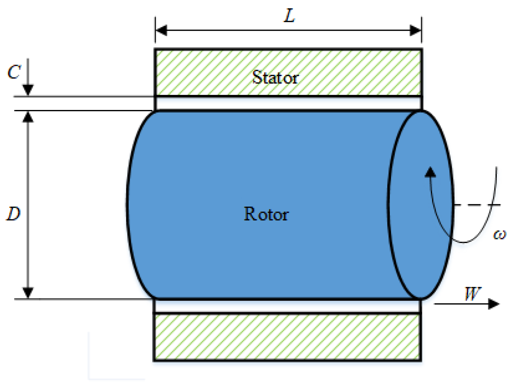
2.1. Geometric Model and Basic Equations Based on the Bulk-Flow Model

Figure 1 depicts the geometry of the smooth annular seal investigated in this paper, where C represents the radial clearance, L represents the length of the seal, and D represents the diameter of the rotor. The two-phase mixture flows along the axis at the speed of W within the clearance between the rotor and stator, while the rotor rotates at the speed of ω.
The governing equations based on the bulk-flow model combined with Hirs’ assumption are adopted in this paper as the basic equations, in which the wall shear stresses are only functions of the local Reynolds number. P, U, and W represent the pressure, circumferential velocity, and axial velocity of the mixture, respectively. For compressible flow within a smooth annular seal clearance, the governing equations, including the continuity equation, the circumferential momentum equation, and the axial momentum equation, are listed as [13]:
( ρ H ) t + ( ρ H U ) x + ( ρ H W ) z = 0
( ρ H U ) t + ρ ( H U 2 ) x + ρ ( H U W ) z = H P x + τ x | 0 H
( ρ H W ) t + ρ ( H U W ) x + ρ ( H W 2 ) z = H P z + τ z | 0 H
where H is the thickness of the lubrication liquid film in the seal. According to Hirs’ theory, the wall shear force can be expressed as [7]:
τ = 1 2 ρ u m 2 f
where f is the friction factor and um is the mean flow velocity relative to the wall where the shear stress is exerted. Therefore, the specific wall shear stresses can be expressed by Equations (5) and (6):
τ x | 0 H = 1 2 ρ ( U U 2 + W 2 f s + ( U R ω ) W 2 + ( U R ω ) 2 f r )
τ z | 0 H = 1 2 ρ W ( U 2 + W 2 f s + W 2 + ( U R ω ) 2 f r )
In the above equations, fs is the friction factor between the fluid and the stator wall, and fr is the friction factor between the fluid and the rotor. Both the friction factors can be defined by Blasius’ friction model, and the equations are shown as Equations (7) and (8), where n and m in the two equations are empirical coefficients obtained through experiments [11]:
f s = n ( ρ H U 2 + W 2 μ ) m
f r = n ( ρ H W 2 + ( W R ω ) 2 μ ) m

2.2. Mixture Properties

In this paper, the liquid flow is assumed to be a homogenous mixture flow, in which spherical bubbles are uniformly distributed. The gas component is assumed to be ideal gas, that is, the gas is isothermal and in thermal equilibrium. The density of the mixture is:
ρ = α ρ G + ( 1 α ) ρ L
where ρG is the gas density, ρL is the liquid density, and α is the gas volume fraction in the mixture. α = 0 represents a pure liquid flow, while α = 1 denotes a pure gas flow. It is worth noting that the gas density is much smaller than that of the liquid component, so the mixture density will be mainly determined by the liquid density. The ideal gas state equation is as follows:
ρ G = P Z C R G T
In the above equation, ZC and RG are the compressibility factor and gas constant, P represents the pressure, and T is the mixture temperature.
Though the mixture viscosity, μ, is an empirical function of liquid viscosity (μL) and gas viscosity (μG), the calculation equations for mixture viscosity, μ, under particular flow conditions based on different theories will differ greatly. According to the flow characteristics within annular seals, this paper adopts the mixture viscosity equation conducted by Award [29] and Fourar [30], shown as:
μ = α μ G + ( 1 α ) μ L + 2 α ( 1 α ) μ G μ L

2.3. Rayleigh–Plesset Equation

Assuming that the mixture in the annular seal is composed of liquid and spherical bubbles containing vapor and gas, the ratio of the volume of all spherical bubbles to the volume of fluid is the gas volume fraction (α). When the temperature in the seal is constant and the liquid is incompressible, the Rayleigh–Plesset equation shown as Equation (12) is introduced in the governing equations to describe the variation in the bubble radius subject to an external pressure [31], under the assumptions that the bubbles are spherical and uniformly distributed, the bubbles of the same cross-section have the same radius, and the bubbles will not collapse and aggregate.
P B P 4 μ e R B D R B D t 2 S R = ρ L R B D 2 R B D t 2 + 3 2 ρ L D 2 R B D t 2
In the above equation, RB is bubble radius, S is surface tension, and μe is liquid equivalent dynamic viscosity, including various damping effects of bubbles, such as acoustic, thermal, and viscous damping. ρL is density of the liquid, PB is the pressure inside the bubble, and P is the pressure of the liquid surrounding the bubble. According to Dalton’s law of partial pressure, the pressure inside the bubble, PB, can be expressed as:
P B = P V + P G
in which PV is the saturated vapor pressure of the liquid at a given temperature, and PG is the pressure inside the bubble. The gas is assumed to be incondensable so that PG can be derived from the ideal gas equation of state.
P G = P G 0 ( R 0 R B ) 3 k
In the above equation, R0 is the radius of the initial bubble, and k is the heat process factor. If the process is isothermal, then k = 1. If the process is adiabatic, k = CP/CV, in which CP and CV are the specific heats of the liquid at constant pressure and volume, respectively [32]. PG0 is the partial pressure of the gas when the bubble is in equilibrium and can be obtained by the bubble statics equation:
P G 0 = P 0 + 2 S R 0 P V
where P0 is the external pressure when the bubble is in the equilibrium position. νe is the liquid equivalent kinematic viscosity, according to the research results of [33], and νe can be calculated by Equation (16). The bubble natural frequency (ωn) can be expressed as Equation (17).
ν e = μ e ρ L = 0.125 ω n R 0 2
ω n = { 1 ρ L R 0 2 [ 3 k ( P 0 P V ) + 2 ( 3 k 1 ) ] S R 0 } 1 2
By solving the RP equation shown in Equation (12), the non-dissolved gas volume fraction (α) can then be calculated according to the functions of R0, RB, and the gas volume fraction at the seal inlet, α0, listed as Equation (18):
α = α 0 ( R B / R 0 ) 3 1 α 0 + α 0 ( R B / R 0 ) 3

2.4. Static Characteristics and Leakage Solution

The zero-order governing equations which describe the steady flow characteristics within the seals can be obtained as Equation (19) to Equation (22) by simplifying Equations (1)–(3) and Equation (12):
ρ W = c o n s t a n t
d P d Z = ρ σ W 2 ρ W d W d Z
ν = ν 0 e a Z
d 2 R B d Z 2 = 3 2 R B ( d R B d Z ) 2 + ( P B P ) L 2 ρ L R B W 2 2 S L 2 ρ L R B 2 W 4 μ e ρ L R B 2 W d R B d Z
The following three boundary conditions are specified for the solution of the zero-order governing equations shown above:
(a)
At the inlet of the annular seal (z = 0), the gas volume fraction, supply pressure, and bubble radius are given according to the initial boundary conditions, i.e.,
α in = α 0 ,   P in = P S ,   R in = R 0
(b)
At the outlet of the annular seal (z = L), the fluid pressure equals to the given outlet pressure, i.e.,
P o u t = P e
(c)
Due to the inertial effect of the fluid, there will be a sudden pressure drop at the seal inlet, and the inlet pressure is a function of axial flow velocity and the empirical entrance loss coefficient ξ [11]:
P z = 0 = P S 1 2 ρ ( 1 + ξ ) W z = 0 2
As shown in Figure 2, a series of numerical solutions for P, W, μ, and ρ can be acquired by solving governing equations, mixture state equations using the fourth-order Runge-Kutta method combined with the boundary conditions. Thus, the gas volume fraction can be obtained according to Equation (17) with the obtained P and ρ. The seal leakage can be obtained by solving the above equations:
Q = 0 2 π R ( ρ H W ) z = L d θ

3. Results and Discussion

3.1. Numerical Method Validation

In this paper, the experimental leakage results of a long smooth seal operating with air-oil mixtures conducted by Childs [28] and a short smooth seal operating with air-oil mixtures conducted by San Andrés [34] are used to validate the accuracy of the proposed method. Childs’ experiments are performed with inlet gas volume fractions (IGVF) of 0%, 2%, 4%, 6%, 8%, and 10%, and San Andrés’ experiments are performed with inlet gas volume fractions from 20% to 90%. The air-oil mixing section of the unit uses two spargers to inject spherical air bubbles with a radius of 10 μm into the oil stream. Table 1 lists the detailed geometrical parameters of the tested seal and the operating conditions.
Figure 3 depicts a comparison of the experimental leakage (mass flow rate) and the calculated ones, respectively based on the present model and San Andrés’ model under the listed operating conditions shown in Table 1. As shown in Figure 3a, under the pressure difference of 31 bars, the leakage flow rates predicted by the two models are in good agreement with the experimental values as the inlet GVFs increase from 0% to 10%. The maximum error of the San Andrés model is 15.1%, while the maximum error of the current model is 8.3%. The predicted values of the two models both decrease with the increasing inlet GVF, while the experimental values basically fluctuate within an interval. Similarly, Figure 3b shows that the predicted leakage rates decrease with the GVF increase at the inlet, while the experimental results show little change with GVF under the pressure difference of 37.9 bars. The different sensitivities to GVF changes are mainly caused by the assumption that the bubbles will not collapse and aggregate, which is a little different from the actual behavior of bubbles. The collapse and aggregation will lead to a sudden pressure change near the bubbles, so that the gas volume will not continue to grow steadily, which will generate an oscillation of pressure, gas volume fraction, and the leakage rate. Additionally, the difficulty of measuring small leakage in the experiments also aggravates the leakage insensitivity to GVF. The maximum calculation error of San Andrés’ method and the method presented in this paper under these conditions are 14% and 11.2%, respectively. To further verify the decreasing trend of the leakage, more comparisons are conducted under the conditions that the inlet GVFs increase from 20% to 90%, as shown in Figure 3c. It can be obtained that both the predicted value based on the proposed method in this paper and the experimental value show a quadratic decrease with the inlet gas volume fraction, and the maximum calculation error of the present model under these conditions is 7.05%.

3.2. Effects of Operating Conditions on the Leakage Flow Rate

Effects of operating conditions, including inlet gas volume fraction and pressure difference, on the leakage flow rates of the model seal, the same as the seal used in Childs’ experiments, are investigated using the proposed method. As shown in Figure 4a, the fractions increase along the axial direction under the pressure difference of 31 bars. Since all the bubbles at the seal inlet have the same radius, a larger inlet GVF means there are more bubbles at the inlet. With the pressure drop changes along axial direction, the bubble radius increases uniformly, so a large number of bubbles lead to a more obvious increasing rate in GVF, especially near the exit, as shown in Figure 4a. Besides, the increasing axial pressure difference obviously raises the gas expansion and the axially distributed GVF, as shown in Figure 4b.
For intuitive comparison, the gas volume fractions within the three regions near the exit shown in Figure 5a are investigated separately. It is indicated in Figure 5b that when the inlet GVF is 2%, the increases in regions 1, 2, and 3 are 1.15%, 1.98%, and 4.72% respectively, while the increases are 3.26%, 5.22%, and 16.43% respectively, when the inlet GVF is 10%. It is worth noting that even if the inlet GVF is as small as 2%, under the actions of large pressure differences, GVF at the seal outlet plane will still become more than 8%. This substantial increase is because the pressure drop around the seal outlet area gradually accelerates, which makes the bubble volume increase dramatically.
Figure 6 depicts the distribution characteristics of mixture density along the axial direction under different GVFs and pressure difference conditions. According to Figure 6a and Equation (9), it can be obtained that the mixture density, ρ, is negatively correlated with the inlet GVF for the reason that the liquid phase is the dominate factor affecting the mixture density. When the inlet GVF is constant, the mixture density shows nonlinear changes with the dimensionless axial seal position. Raising the inlet GVF could increase the local GVF along the axial direction under the same pressure difference, which will result in a much smaller mixture density. Figure 6b shows the variation of the mixture density at the dimensionless axial seal position with changing pressure difference. As is shown, pressure difference has little effect on the mixture density at the inlet plane. However, the pressure difference along the axial direction has a huge impact on the internal flow and fluid characteristics within the seal clearances, i.e., the greater the pressure difference is, the lower the mixture density is at the outlet plane.
Figure 7a illustrates the mixture viscosity changes along the axial direction with increasing inlet gas content when ΔP = 31 bars. According to Equation (10), the viscosity of the liquid phase is two orders of magnitude greater than the viscosity of the gas phase, so the viscosity of the liquid phase dominates. Therefore, the mixture viscosity decreases as the GVF increases. When the inlet GVF is constant, the decreasing rate of the mixture viscosity along the axial direction gradually increases. At the same dimensionless axial seal position, the increase of inlet GVF results in the mixture viscosity decreasing faster. As illustrated in Figure 7b, the gas volume fraction increases as the pressure difference increases, resulting in a decrease in the mixture viscosity and an intensified decreasing rate near the seal outlet plane.
The axial pressure drop across the seal with increasing inlet GVF is shown in Figure 8. As shown in Figure 8a, when the pressure difference, ΔP, is 31 bars and the inlet GVF is 0 (i.e., under the pure oil condition), the axial pressure drop is linear. However, when the air is injected into the seal, the axial pressure drop shows a non-linear change. From the seal inlet plane to the outlet plane, the pressure drop gradually increases, and the pressure drop near the exit region decreases sharply. According to Equation (19), the product of mixture density and axial velocity under steady flow is a constant. Thus, the axial velocity of the mixture increases with the decreasing density as the bubble radius and GVF increase. Then, increasing the axial velocity will further raise the axial pressure gradient, pressure drop, and the gas volume fraction, which leads to a decrease in density and an increase in pressure drop, thus forming a positive feedback, which makes the pressure drop gradually increase along the axial direction. Most notably, as shown in Figure 8, there is a sudden pressure drop at the seal inlet position. This phenomenon is called the Lomakin effect, induced by the fluid inertia. In addition, increasing the gas content reduces the inlet pressure drop. Figure 8b shows that increasing inlet GVF will decrease the inlet pressure drop and increase the non-linearity of the pressure drop when ΔP equals to 37.9 bars. When ΔP is 48.3 bars, as shown in Figure 8c, the Lomakin effect behaves the same, but the pressure curve trend becomes steeper as the inlet GVF increases.

3.3. Effects of Bubble Radius on the Leakage Flow Rate

Figure 9a,b respectively, show the GVF distribution and pressure distribution under different bubble radii, when the inlet volume fraction is 10% and the pressure difference is 48.3 bars. As is shown, the gas volume fraction distribution curve and the pressure curve under different bubble radii basically coincide, except at the seal outlet position, which means that the bubble radius has little effect on axial GVF and almost no effects on the pressure distribution. The number of bubbles decreases due to the increase in bubble radius under the same GVF conditions, and according to the numerical solution of Equation (22), it can be obtained that the volume of bubbles with a smaller radius increases more rapidly under the same pressure drop. Therefore, significant differences of volume fractions under a series of bubble radii are generated. Figure 10 shows the mixture properties, including density and viscosity along the axial direction with the changing inlet bubble radius. As expected, the mixture density and viscosity are insensitive to the variation of bubble radius, and both curves basically do not change with the bubble radius. Combined with the trends of the gas volume fraction at the seal outlet position shown in Figure 9a, it can be obtained that the mixture density and viscosity show sudden decreases at the seal outlet position, as shown in Figure 10. Besides, the decreases are more obvious for the conditions with a smaller bubble radius.
Figure 11 compares the variation of the seal leakage with inlet GVF but under bubble radii of 0.01, 0.1, and 0.15 mm, respectively. The comparisons show that increasing the bubble radius will slightly reduce the seal leakage, which corresponds to the slight increase in GVF shown in Figure 9a, but the effect is not obvious, especially in the operating conditions with small inlet GVF.

3.4. Effects of Seal Clearance on the Leakage Flow Rate

Figure 12 depicts the predicted seal leakage of the model seals with clearances of 0.138, 0.188, 0.238, and 0.288 mm under six inlet GVFs. It is indicated that all the leakage rates of different model seals decrease with the increase of inlet GVFs. The clearance increases will thicken the liquid film and reduce the influences of the shear force on the internal flow, which eventually results in a seal leakage increase, as illustrated in Figure 12. Figure 13a,b respectively, compare the GVF distribution and pressure distribution within different model seals along the axial direction. It can be obtained that in the front half of the seal, gas volume fractions change slowly, basically around 5%, but change drastically in the back half with a fraction variation of around 30%. The trends shown in Figure 13b indicate that seal clearance has great effects on the pressure distribution characteristics due to the fluid inertia effect, especially at the inlet position, where there is a sudden pressure drop. Under the same pressure difference, the axial velocity of the fluid within large clearance will be faster, which will directly improve the inlet pressure loss at the inlet. Besides, as a result of Bernoulli principle, the axial pressure decrease rates of the larger clearance seals are much smaller due to the higher axial velocity.
Figure 14 shows the mixture properties including density and viscosity within seals with four different clearances. Along the axial direction, the bubbles begin to expand, thus the gas volume fraction gradually increases, which results in a decrease in mixture density. The smaller the seal clearance is, the more obvious the downward trend is. The mixture viscosity change in Figure 14b shows similar characteristics to the density change, i.e., the viscosity gradually decreases along the axial direction and decreases rapidly near the outlet position.

4. Conclusions

In this paper, a new solution method for static characteristics and leakage predictions of annular seals operating with gas-liquid mixture was established by introducing the Rayleigh–Plesset equation to the governing equations based on the bulk-flow model. The accuracy of the proposed method was verified by comparison with the experimental leakage rates conducted by Childs and San Andrés. With the proposed calculation method, leakage rates and the static characteristics, including GVF distributions and pressure distributions within the seals, mixture density, and viscosity of the model seals under different operating conditions, were predicted and compared. Some conclusions can be drawn as below:
(a)
Seal leakage decreased with the increasing inlet GVF but increased with the pressure difference. Both the mixture density and viscosity decreased with the increasing inlet GVF and pressure difference.
(b)
Axial pressure drop was large around the seal outlet, which led to a rather large GVF expansion. With the same inlet GVF, the outlet GVF will increase intensely under a larger pressure difference.
(c)
Bubble radius had little effect on the leakage rates, GVF distribution, pressure characteristics, mixture density, and viscosity, while the leakage decreased slightly with the increase of the bubble radius.
(d)
Leakage rates of the model seals with bigger clearance are more sensitive to the inlet GVF changes. The smaller the seal clearance is, the more dramatically the density and viscosity around the seal exit decrease.

Author Contributions

Methodology, C.Z. and L.Z.; software, C.Z.; validation, J.G. and B.C.; investigation, B.C. and G.C.; writing—original draft preparation, C.Z. and L.Z.; funding acquisition, L.Z. and B.C. All authors have read and agreed to the published version of the manuscript.

Funding

This research was funded by the National Natural Science Foundation of China (Grant No. 51976199 and Grant No. U1709209), the Key Research and Development Program of Zhejiang Province (2020C01027), and the High-Level Talent Support Program of Zhejiang Province (2019R51002).

Institutional Review Board Statement

Not applicable.

Informed Consent Statement

Not applicable.

Data Availability Statement

The numerical and experimental data used to support the findings of this study are included within the article.

Conflicts of Interest

The authors declare no conflict of interest.

Nomenclature

adimensionless coefficient defined in Equation (21)
Cnominal seal radial clearance (m)
Dseal diameter (m)
ffriction factor
frfriction factor relative to the rotor
fsfriction factor relative to the stator
Hseal radial clearance (m)
kheat process factor
Lseal length (m)
n, mcoefficients for friction factors
Pfluid pressure (pa)
ΔPpressure difference (pa)
PBpressure inside the bubble (pa)
Peexit pressure (pa)
PGpressure provided by the gas part of the bubble (pa)
PSsupply pressure (pa)
PVvapor pressure (pa)
Qseal leakage (kg/s)
Rseal radius (m)
RBbubble radius (m)
RGgas constant
R0bubble radius at the inlet (m)
Ssurface tension (N)
ttime (s)
Tsupply temperature (℃)
Ucircumferential velocity (m/s)
Waxial velocity (m/s)
ummean flow velocity relative to the wall (m/s)
Zdimensionless axial seal position
ZCgas compressibility factor
Greek symbols
αgas volume fraction
α0inlet gas volume fraction
θcircumferential angle (rad)
μfluid viscosity (N.s/m2)
μG, μLgas and liquid viscosity (N.s/m2)
μeliquid equivalent viscosity (N.s/m2)
νeliquid equivalent kinematic viscosity (m2/s)
ξinlet pressure loss coefficient
ρfluid density (kg/m3)
ρG, ρLgas and liquid density (kg/m3)
σdimensionless coefficient defined in Equation (20)
τwall shear stress (pa)
τx, τzcircumferential and axial wall shear stresses (pa)
ωrotor speed (rad/s)
ωnbubble natural frequency

References

  1. Black, H.F. Effects of Hydraulic Forces in Annular Pressure Seals on the Vibrations of Centrifugal Pump Rotors. J. Mech. Eng. Sci. 1969, 11, 206–213. [Google Scholar] [CrossRef]
  2. Black, H.F.; Jessen, D.N. Dynamics hybrid properties of annular pressure seals. Proc. J. Mech. Eng. 1970, 184, 92–100. [Google Scholar]
  3. Black, H.F.; Jessen, D.N. Effects of high-pressure ring seals on pump rotor vibrations. ASME Pap. 1971, 71, 38–46. [Google Scholar]
  4. Black, H.F. Calculation of Forced Whirling and Stability of Centrifugal Pump Rotor Systems. J. Eng. Ind. 1974, 96, 1076–1081. [Google Scholar] [CrossRef]
  5. Allaire, P.E.; Lee, C.C.; Gunter, E.J. Dynamics of Short Eccentric Plain Seals with High Axial Reynolds Number. J. Spacecr. Rocket. 1979, 15, 341–347. [Google Scholar] [CrossRef]
  6. Hirs, G.G. Fundamentals of a Bulk-Flow Theory for Turbulent Lubricant Films. Ph.D. Thesis, University of Technology Delft, Delft, The Netherlands, 1970. [Google Scholar]
  7. Hirs, G.G. A Bulk-Flow Theory for Turbulence in Lubricant Films. J. Lubr. Technol. 1973, 95, 137–145. [Google Scholar] [CrossRef]
  8. Blasius, H. Das Aehnlichkeitsgesetz bei Reibungsvorgängen in Flüssigkeiten. Mitt. Forsch. Geb. Ing. 1913, 131, 1–41. [Google Scholar] [CrossRef] [Green Version]
  9. Davies, S.J.; White, C.M. An experimental study of the flow of water in pipes of rectangular section. Proc. R. Soc. London. Ser. A Math. Phys. Sci. 1928, 119, 92–107. [Google Scholar] [CrossRef] [Green Version]
  10. Couette, M.M. Etudes sur le frottement des liquides. Ann. Chem. Phys. 1890, 21, 256–264. [Google Scholar]
  11. Childs, D.W. Dynamic Analysis of Turbulent Annular Seals Based on Hirs’ Lubrication Equation. J. Lubr. Technol. 1983, 105, 429–436. [Google Scholar] [CrossRef]
  12. Childs, D.W. Finite-Length Solutions for Rotordynamic Coefficients of Turbulent Annular Seals. J. Lubr. Technol. 1983, 105, 437–444. [Google Scholar] [CrossRef]
  13. Childs, D.W. Rotordynamic moment coefficients for finite length turbulent seals. Energ. Elettr. 1982, 48, 371–378. [Google Scholar]
  14. Nelson, C.C. Rotordynamic Coefficients for Compressible Flow in Tapered Annular Seals. J. Tribol. 1985, 107, 318–325. [Google Scholar] [CrossRef]
  15. Nelson, C.C.; Nguyen, D.T. Comparison of Hirs’ Equation with Moody’s Equation for Determining Rotordynamic Coefficients of Annular Pressure Seals. J. Tribol. 1987, 109, 144–148. [Google Scholar] [CrossRef] [Green Version]
  16. Beatty, P.A.; Hughes, W.F. Turbulent Two-Phase Flow in Annular Seals. ASLE Trans. 1987, 30, 11–18. [Google Scholar] [CrossRef]
  17. Arauz, G.L.; Andrés, L.S. Analysis of Two-Phase Flow in Cryogenic Damper Seals—Part I: Theoretical Model. J. Tribol. 1998, 120, 221–227. [Google Scholar] [CrossRef]
  18. Arauz, G.L.; Andrés, L.S. Analysis of Two-Phase Flow in Cryogenic Damper Seals—Part II: Model Validation and Predictions. J. Tribol. 1998, 120, 228–233. [Google Scholar] [CrossRef]
  19. Hendricks, R.C. Straight Cylindrical Seal for High-Performance Turbomachines; NASA TP-1850; NASA: Cleveland, OH, USA, 1987.
  20. Iwatsubo, T.; Nishino, T. An experimental study on the static and dynamic characteristics of pump annular seals. In Proceedings of the 7th Work-Shop on Rotordynamic Instability Problems in High Performance Turbomachinery, College Station, TX, USA, 10–12 May 1993. [Google Scholar]
  21. Arghir, M.; Zerarka, A.G. Pineau, Rotordynamic analysis of textured annular seals with multiphase (bubbly) flow. INCAS Bull. 2011, 3, 3–13. [Google Scholar]
  22. Diaz, S.E. The Effect of Air Entrapment on the Performance of Squeeze Film Dampers: Experiments and Analysis. Ph.D. Thesis, Texas A&M University, College Station, TX, USA, 1999. [Google Scholar]
  23. Alehossein, H.; Qin, Z. Numerical analysis of Rayleigh–Plesset equation for cavitating water jets. Int. J. Numer. Methods Eng. 2007, 72, 780–807. [Google Scholar] [CrossRef]
  24. Andrés, L.S. Rotordynamic Force Coefficients of Bubbly Mixture Annular Pressure Seals. J. Eng. Gas Turbines Power 2012, 134, 022503. [Google Scholar] [CrossRef]
  25. Ma, X.; Meng, X.; Wang, Y.; Peng, X. Suction effect of cavitation in the reverse-spiral-grooved mechanical face seals. Tribol. Int. 2019, 132, 142–153. [Google Scholar] [CrossRef]
  26. Andrés, L.S.; Lu, X.; Liu, Q. Measurements of Flow Rate and Force Coefficients in a Short-Length Annular Seal Supplied with a Liquid/Gas Mixture (Stationary Journal). Tribol. Trans. 2016, 59, 758–767. [Google Scholar] [CrossRef]
  27. Andrés, L.S.; Lu, X. Leakage, Drag Power, and Rotordynamic Force Coefficients of an Air in Oil (Wet) Annular Seal. J. Eng. Gas Turbines Power 2018, 140, 012505. [Google Scholar] [CrossRef]
  28. Zhang, M.; Childs, D.W.; Shrestha, H. Experimental study of the leakage and rotordynamic coefficients of a long-smooth seal with two-phase, mainly oil mixtures. ASME J. Tribol. 2019, 141, 042201. [Google Scholar] [CrossRef]
  29. Awad, M.; Muzychka, Y. Effective property models for homogeneous two-phase flows. Exp. Therm. Fluid Sci. 2008, 33, 106–113. [Google Scholar] [CrossRef]
  30. Fourar, M.; Bories, S. Experimental study of air-water two-phase flow through a fracture (narrow channel). Int. J. Multiph. Flow 1995, 21, 621–637. [Google Scholar] [CrossRef]
  31. Brennen, C.E. Cavitation and Bubble Dynamics; Oxford Engineering Series; Oxford University Press: New York, NY, USA, 2013; Volume 44. [Google Scholar]
  32. Qin, Z. Investigation of the Cavitation Mechanism and Erosion of Submerged High Pressure Water Jets. Ph.D. Thesis, The University of Queensland, Queensland, Australia, 2004. [Google Scholar]
  33. Wang, Y.-C.; Chen, E. Effects of phase relative motion on critical bubbly flows through a converging–diverging nozzle. Phys. Fluids 2002, 14, 3215–3223. [Google Scholar] [CrossRef]
  34. Andrés, L.S.; Yang, J.; Lu, X. On the Leakage, Torque, and Dynamic Force Coefficients of Air in Oil (Wet) Annular Seal: A Computational Fluid Dynamics Analysis Anchored to Test Data. J. Eng. Gas Turbines Power 2018, 141, 021008. [Google Scholar] [CrossRef]
Figure 1. Geometrical parameters of an annular smooth seal.
Jmse 09 00523 g001
Figure 2. Program flow chart.
Jmse 09 00523 g002
Figure 3. Mass flow rates versus inlet gas volume fraction based on the present model and experiments. (a) ΔP = 31 bars, (b) ΔP = 37.9 bars, (c) ΔP = 1.5 bars.
Jmse 09 00523 g003aJmse 09 00523 g003b
Figure 4. GVF distribution characteristics along the axial direction under different operating conditions. (a) GVF under different inlet GVFs for ΔP = 31 bars, (b) GVF under different pressure differences for inlet GVF = 10%.
Jmse 09 00523 g004
Figure 5. GVF distribution characteristics along the axial direction at specific regions. (a) Schematic diagram of the three specific regions, (b) GVF increment versus inlet GVF in regions 1, 2, and 3.
Jmse 09 00523 g005
Figure 6. Mixture density along the axial direction under different conditions. (a) Under different inlet GVFs with a constant ΔP of 31 bars, (b) under different pressure differences with a constant inlet GVF of 10%.
Jmse 09 00523 g006
Figure 7. Mixture viscosity along the axial direction under different conditions. (a) Under different inlet GVFs with a constant ΔP of 31 bars, (b) under different pressure differences with a constant inlet GVF of 10%.
Jmse 09 00523 g007
Figure 8. Pressure profile along the axial direction under different inlet GVFs. (a) ΔP = 31 bars, (b) ΔP = 37.9 bars, (c) ΔP = 48.3 bars.
Jmse 09 00523 g008aJmse 09 00523 g008b
Figure 9. GVF and pressure distribution along the axial direction within the model seal under different bubble radii for ΔP = 48.3 bars. (a) GVF distribution, (b) pressure distribution.
Jmse 09 00523 g009
Figure 10. Mixture properties’ changes along the axial direction of the model seal under different bubble radii for ΔP = 48.3 bars. (a) Density changes, (b) viscosity changes.
Jmse 09 00523 g010
Figure 11. Seal leakage (mass flow rate) of the model seal versus inlet GVF under different bubble radii for ΔP = 48.3 bars.
Jmse 09 00523 g011
Figure 12. Seal leakage (mass flow rate) of model seals with different clearances versus inlet GVF under the conditions of ΔP = 48.3 bars.
Jmse 09 00523 g012
Figure 13. GVF and pressure distribution along the axial direction within the model seals with different clearances under the conditions of inlet GVF = 10% and ΔP = 48.3 bars. (a) GVF distribution, (b) pressure distribution.
Jmse 09 00523 g013
Figure 14. Mixture properties’ changes along the axial direction of the model seals with different clearances under the conditions of inlet GVF = 10%, ΔP = 48.3 bars. (a) Density changes, (b) viscosity changes.
Jmse 09 00523 g014
Table 1. Seal geometrical parameters and operational conditions [28].
ParameterValue
Diameter, D0.089306 m
Length, L/D0.65
Clearance, C0.188 mm
Inlet loss, ξ0.25
Supply temperature, T39.4 °C
Pressure difference, ΔP3137.9 bars
Exit pressure, Pe6.9 bars
Rotor speed, ω10 krpm
Bubble radius, R010 μm
Liquid componentPSF-5cSt
Gas componentair
Publisher’s Note: MDPI stays neutral with regard to jurisdictional claims in published maps and institutional affiliations.

