Article

Optimum Curvature Characteristics of Body/Caudal Fin Locomotion

School of Mechatronics Engineering, Harbin Institute of Technology, Harbin 150001, China
*
Author to whom correspondence should be addressed.
J. Mar. Sci. Eng. 2021, 9(5), 537; https://doi.org/10.3390/jmse9050537
Submission received: 19 April 2021 / Revised: 9 May 2021 / Accepted: 11 May 2021 / Published: 17 May 2021
(This article belongs to the Section Ocean Engineering)

Abstract

:
Fish propelled by body and/or caudal fin (BCF) locomotion can achieve high-efficiency and high-speed swimming performance, by changing their body motion to interact with external fluids. This flexural body motion can be prescribed through its curvature profile. This work indicates that when the fish swims with high efficiency, the curvature amplitude reaches a maximum at the caudal peduncle. In the case of high-speed swimming, the curvature amplitude shows three maxima on the entire body length. It is also demonstrated that, when the Reynolds number is in the range of 104–106, the swimming speed, stride length, and Cost of Transport (COT) are all positively correlated with the tail-beat frequency. A sensitivity analysis of curvature amplitude explains which locations change the most when the fish switches from the high-efficiency swimming mode to the high-speed swimming mode. The comparison among three kinds of BCF fish shows that the optimal swimming performance of thunniform fish is almost the same as that of carangiform fish, while it is better not to neglect the reaction force acting on an anguilliform fish. This study provides a reference for curvature control of bionic fish in a future time.

1. Introduction

After hundreds of millions of years of evolution, fish show superiority in high-efficiency and high-speed motion, which has attracted the attention of many researchers. The study on bionic fish can lead to a new design of Automatic Underwater Vehicles (AUV). In the nature, most fishes use the body and/or caudal fin (BCF) propulsion to generate thrust. These fishes are distinguished into three categories: anguilliform mode, carangiform mode, and thunniform mode (Figure 1). The paramount differences between the three modes are the amplitude envelope of the propulsive wave and the wavelength [1,2].
A fish uses both the active and passive mechanisms while swimming [3]. Passive swimming reacts to external flow with no muscle activation [4]. In contrast, active swimming implies swimming generated through muscular activation [5]. BCF fish can autonomously control their curvature profile to achieve the compliant body motion and realize active/passive swimming [6,7,8,9,10,11]. Hence, the research on curvature profile is important to understand the fish locomotion mechanism. The curvature distribution is closely related to the materials and shape of the fish body, including soft tissue (tendons, muscle, and ligaments) and hard parts (fin rays and vertebral column). From the biological perspective, the curvature is controlled mostly by internal muscular activation. Specifically, fish can receive the stretch receptors that depend on body curvature to the central nervous system and then drive the calcium dynamics to affect the muscle activity, which can further modulate the swimming behavior [12,13]. Many in vivo experiments and electromyogram analyses have been conducted to discover the neuro–musculo–mechanical model, and much progress on the model has been made [14,15,16,17,18]. Williams and Bowtell developed a simple dynamic model to describe the interaction between body curvature and muscle activation [19,20]. McMillen et al. suggested that fish neuromuscular systems produce an intrinsic preferred curvature that can be derived from in vivo experiments [21,22]. Considering the complexity and the difficulty of the comprehensive model, some researchers turn to study the curvature profile directly instead of the connection to muscular activation. Van Rees et al. and Eloy combined different hydrodynamic models and bi-objective optimization algorithms to obtain the optimal curvature profiles and body shapes for undulatory swimming [23,24]. Such numerical optimization can help overcome some limiting constraints in reality. Nevertheless, these optimized body shapes show a slightly unsmooth or strange geometry when compared to real fish. One of the possible reasons is that the fish in nature faces many constraints in the process of evolution. In this paper, empirical body shapes obtained by biological data of BCF fish are used to avoid this problem and the corresponding analysis of optimal curvature profiles can provide a more reasonable value of information.
Certain techniques have been used to achieve variable curvature structures [3,25,26,27,28,29]. A common method is to tune the pressure of the soft pneumatic actuator. White et al. changed the local curvature by developing a Tunabot with different degrees of freedom [28,29]. In addition, some accurate curvature control methods have been proposed and applied in the field of soft robotics [30,31,32]. The developments in structure fabrication and the control methods, in turn, demand the further investigation of optimal curvature distribution of BCF fish. Therefore, swimming performance optimization through curvature control will become the focus of future related research on bionic robotic fish. The premise of curvature control is to understand the impact of varying the curvature distribution on swimming performance, which is discussed in this study.
This paper is organized as follows: Section 2 describes the optimization problem of swimming performance. Section 3 presents the optimization results including the swimming motions, curvature profiles, the frequency effect, the change mechanism of curvature amplitude, and comparison among BCF fishes. Section 4 discusses the similarities and differences between our optimization and other optimizations. Finally, conclusions are summarized in Section 5.

2. Materials and Methods

2.1. Optimization Problem Definition

Here we take the carangiform fish as an example for optimization. The optimization of the other two kinds of BCF fish will be conducted in Section 3.4. The shape of carangiform fish is determined by the empirical equations in [33] (see Figure 2). The views are set out in the global coordinate system OXYZ where Y-axis is horizontal and Z-axis is vertical. The X-axis is determined by the right-handed rule. The swimming direction is along with the negative Y-axis.
The midline kinematics can be described by a curvature profile κ(s,t), defined as an amplitude function K(s) multiplied by a traveling wave [23], as:
κ ( s , t ) = K ( s ) cos [ 2 π ( t T τ ( s ) s L ) ]
where t is the time, T = 1 s is the tail-beat cycle, and τ(s) determines the wavelength. Both K(s) and τ(s) are functions fitted at n = 11 interpolation points that are evenly distributed on the midline. Considering the boundary conditions, K(0) = K(L) = τ(0) = 0, the kinematic optimization problem includes 19 degrees of freedom in total. According to the biological data gathered by Zuo Cui, the range of τ(s) is set as 0.5–2 [34].
If a specific curvature profile is given, the swimming kinematics can be determined according to the reduced-order dynamic model developed by Eloy [24]. The general introduction of this model is as follows (shown in Figure 3). Once the initial curvature profile is set, the angle θ between the tangent to the midline and horizontal axis is obtained based on the mathematical definition of curvature. The position of any point r = (x, y) on the midline is then derived by employing the integral to a trigonometric function of θ. As a result, the velocity components on the tangential and normal direction at any point of the midline, namely u and v, can be calculated through the differential to the position function and the projection analysis.
The forces acting on the fish body that include reaction force Fm, skin-friction drag F//, form drag Fform, and resistive force F, can be expressed as the functions of the velocity components. Their empirical formulas are shown in Equations (2)–(5), respectively. The reaction forces are derived by the large-amplitude elongated-body theory [35]. The description of skin-friction drag and resistive force is obtained by the hydrodynamics analysis of Taylor [36]. The empirical formula of form drag caused by the non-streamlined body is concluded by Hoerner [37].
d F m = ( ( m u v n 0.5 m v 2 t ) s m v n t ) d s
d F / / = 2.9 ρ | ν a v | u d s   t
F form = 0.33 ρ U 0 2 × max ( b ) L S   e Y
d F = C D a ρ v | v | d s   n
where t and n are the unit vectors of tangential and normal directions of midlines, respectively. ρ = 1000 Kg/m3 is the density of both fish and fluid. m = ρ a2 is the added mass of each section. ν = 10−6 m2/s is the kinematic viscosity of the fluid. CD = 2 − b/a is the approximation of the resistive force coefficient. U0 is the mean tangential velocity at the fish head. S = 0.0043 is a number that describes the streamlining of the fish body.
The constants of integration that emerged during the process, such as θ0, x0, and y0, can be solved by the conservation of momentum and angular momentum (Equations (6) and (7)). Thus, the undulatory behavior is fully understood.
F form + 0 L d F / / + d F m + d F M d 2 r d t 2 d s = 0
0 L I d 2 θ d t 2 e z d s + ( d F / / + d F m + d F M d 2 r d t 2 ) × r d s = 0
where M = ρ πab is the fish mass of each section. I = 0.25 ρ πab3 is the moment of inertia of each section.
The indices used in the simulation to measure the swimming performance are shown in Equations (8) and (9). Consequently, each curvature profile has its corresponding swimming performance. The bi-objective optimization was adopted for obtaining the maximum relative swimming speed U* and the minimum Cost of Transport (COT), deriving the optimal curvature profile.
U * = U / L
COT = P tm M tot g U = P s + P musc M tot g U = 0.1327 M tot 0.8 + 5 P tot M tot g U
where g is the acceleration of gravity and Mtot is the total fish mass. The total metabolic power Ptm is the sum of standard metabolic rate Ps and the metabolic power Pmusc consumed by the swimming muscles [38,39]. The unit of U* is Body Length/s, namely, BL/s. COT quantifies the total energy consumption per unit mass and distance [40]. The higher the value of COT, the lower the efficiency. Ptot serves as the total power required for swimming, which is described in Equation (10).
P tot = P m + P + P / / + P form + P i
where Pm, P, Pform, and P are the powers consumed by reaction force, skin-friction drag, form drag, and resistive force, respectively. These powers are easy to calculate by multiplying the forces and the corresponding velocities. Pi is the internal dissipation power (see Equation (11)).
P i = 0 L μ I ( d 2 θ d s d t ) 2 d s
where μ = 1000 Pa s is the internal viscosity of fish and the brackets mean time averaging.
The optimization problem is concluded here. Given the shape of carangiform fish, (K1, K2, …, Kn−1, τ1, τ2, …, τn) were chosen as variables and the two objective functions were the maximum U* and the minimum COT.
In the process of parameter settings, if the Kmax value is too high, the search space will become wider and the simulation time will be longer, whereas, if the Kmax value is too low, true optimization results may not be obtained. Therefore, it is necessary to set the appropriate value of Kmax. Gazzola et al., Van Rees et al. and Eloy set this value to 2π/L, 3π/L, 10/L, respectively [23,24,41]. In this paper, the Kmax value was initially set to 10π/L (a number high enough to produce simulation results), while the maximum values of K corresponding to different lengths could be thus obtained once optimization was completed. The simulation showed that Kmax was approximately inversely proportional to L. The inverse proportional function was fitted as Kmax = 8.4/L. This restriction can be relaxed in some cases, which are later discussed in Section 3.3.

2.2. Optimization Algorithm

The NSGA-II algorithm for bi-objective optimization was used in this paper. NSGA-II is nowadays one of the most popular and efficient multi-objective algorithms [42,43]. Before introducing NSGA-II, there are two important concepts to understand: dominance and Pareto front. For two individuals G1 and G2, if U*(G1) > U*(G2), COT(G1) ≤ COT(G2) or U*(G1) ≥ U*(G2), COT(G1) < COT(G2), G1 is said to dominate G2. Therefore, the set of all non-dominated points is called the Pareto front. Like genetic algorithms, the NSGA-II procedure is roughly as follows (Figure 4). First, an offspring population was generated from the parent population through crossover and mutation. The probability for crossover was 0.8; next, offspring and parent population were combined into a mixed population and sorted according to non-dominated sorting (the conception of crowding distance was not used in our simulation); following, the set of all non-dominated points was selected for the next parent generation; finally, the above steps were repeated until the termination condition was met. The initial size and the maximum size of the population were set as 20 and 2000, respectively. The detailed algorithm implementation was coded using the open-source software Python.

3. Results

3.1. Reference Case

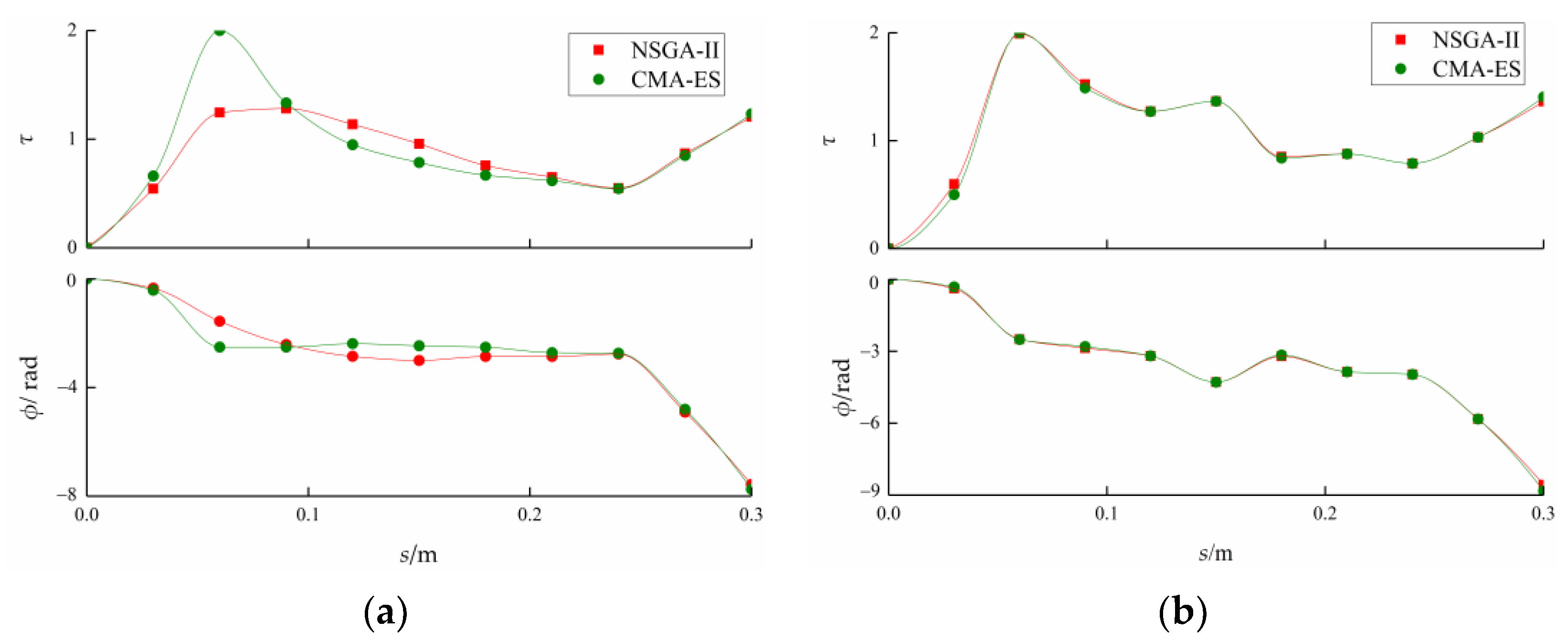
The case of the tail-beat frequency f = 1 Hz was taken as a reference case. Setting φ(s) = −2π·τ(s)·s/L, φ(s) was the phase of the curvature profile. For the swimming forms of minimum COT and maximum swimming speed in the reference case, the distributions of τ and φ along the body length are both depicted in Figure 5. To validate the effectiveness of the simulation results, a single-objective optimization algorithm, covariance matrix adaptation evolution strategy (CMA-ES), was used to obtain the distributions of τ for the above-mentioned forms. It can be seen from Figure 5 that the numerical solutions based on CMA-ES were in good agreement with these based on NSGA-II. Furthermore, the distributions of τ and φ were similar for the two cases. τ increased sharply at first, followed by a decrease, but then again increased in the last fifth of body length. The phase distribution presented a step shape in general. As for the disagreement between algorithms around three-tenths of the body length for the minimum COT case (Figure 5a), it can be explained as follows. The curvature amplitude in this location was near zero for the minimum COT case (shown in Figure 6). Therefore, according to Equation (1), the change in τ value in this location had little effect on swimming performance. In spite of the disagreement of τ value in this location, the swimming performance obtained by the two algorithms was almost equal.
Six typical swimming forms A-F were extracted from the reference case (the speed range was divided into fifths). Figure 6 presents the amplitude envelopes of these curvature profiles. When U* was small (Case A in Figure 6), the curvature amplitude was near zero along with the first 2/3 of the body length, while its peak value appeared at the caudal peduncle. When U* reached the maximum (Case F in Figure 6), there were three local peaks of curvature amplitude in the whole body length, which were at the head, at the 2/3 of the body length, and at the caudal peduncle, respectively. It indicates that the undulatory motion mainly concentrates in the last third of the body length to achieve minimum COT, and the large undulation also exists in the head part to reach maximum speed. In nature, the fish head needs to keep rigid to protect the brain tissue, so the curvature of the head part cannot reach the simulation value of the swimming form F. It can therefore be assumed that the evolution of natural fish inclines towards the direction of maximizing swimming efficiency. However, this does not mean that the simulation result of F is meaningless. If different kinds of soft materials are applied in the fabrication of biomimetic fish to realize the curvature distribution of F, the simulated maximum speed can also be achieved in reality.

3.2. Frequency Effect

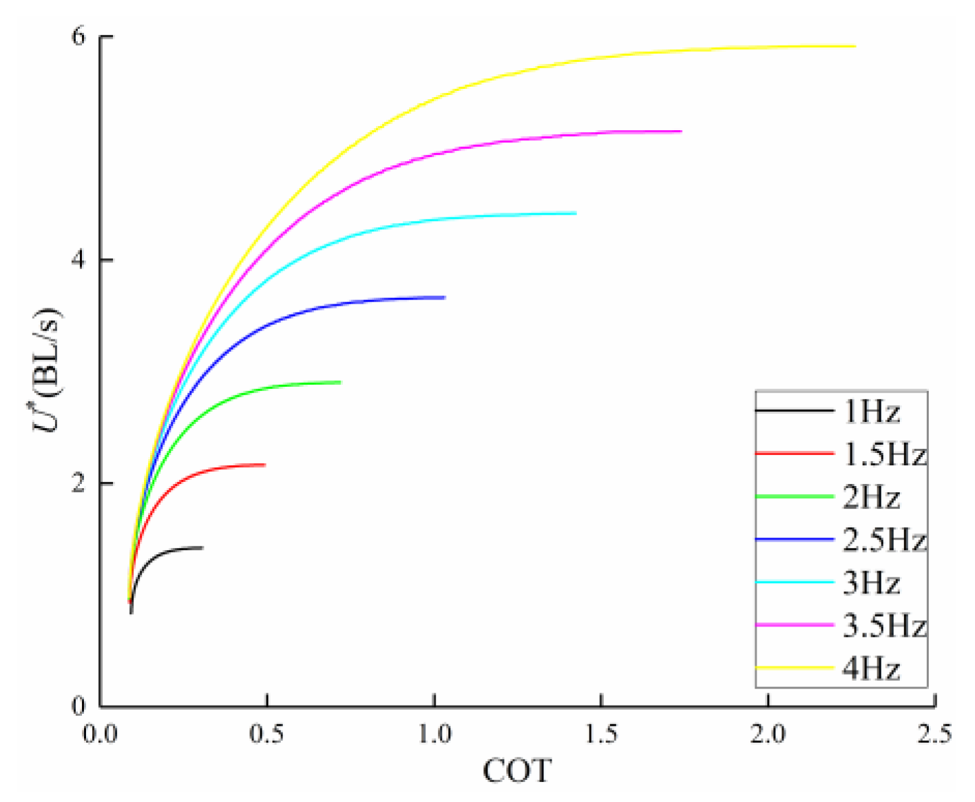
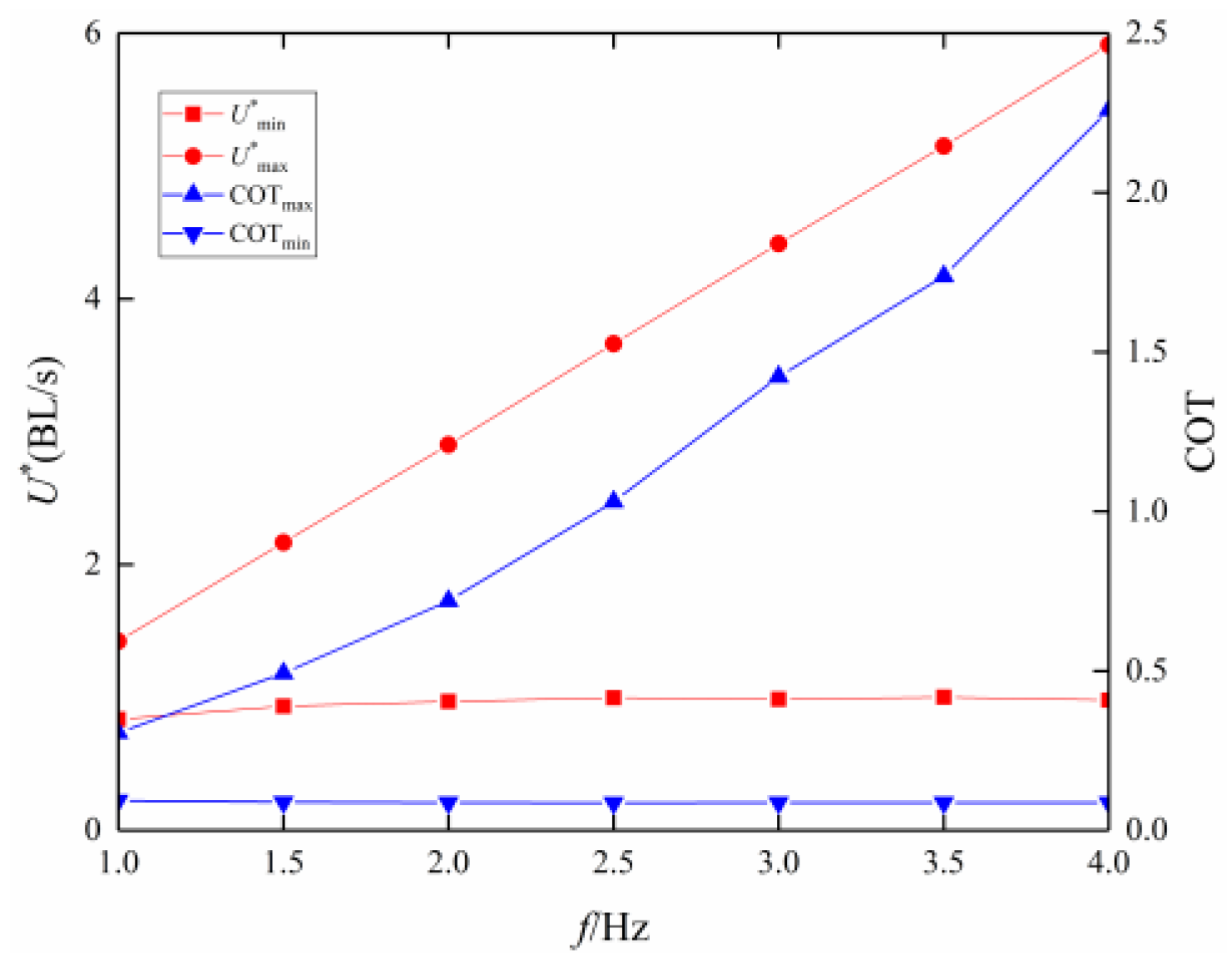
Yue and Tokić showed that when the fish mass is about 0.5 kg (the fish mass in this paper was 0.48 kg), the range of tail-beat frequency is 1.25–4.5 Hz [44]. Therefore, optimization results of U* and COT at various tail-beat frequencies within the range of 1 Hz–4 Hz were obtained (Figure 7). Figure 7 and Figure 8 demonstrate that the maximum U* and the maximum COT increased linearly with frequency while the minimum U* and the minimum COT remained constant. Real fish swimming data observed by Videler and Hess [7] indicate that the swimming speed is proportional to frequency when the frequency is in the range of 1 Hz–14 Hz, also supporting the above result. Another evaluation index often used in other references is introduced here: the stride length U’ = U*/f [7,24]. The stride length is a dimensionless number that is the number of fish lengths travelled during one tail-beat period. In our simulation, the maximum U’ remained stable at around 1.42, and the minimum U’ decreased from 0.84 to 0.245, with the increasing frequency.
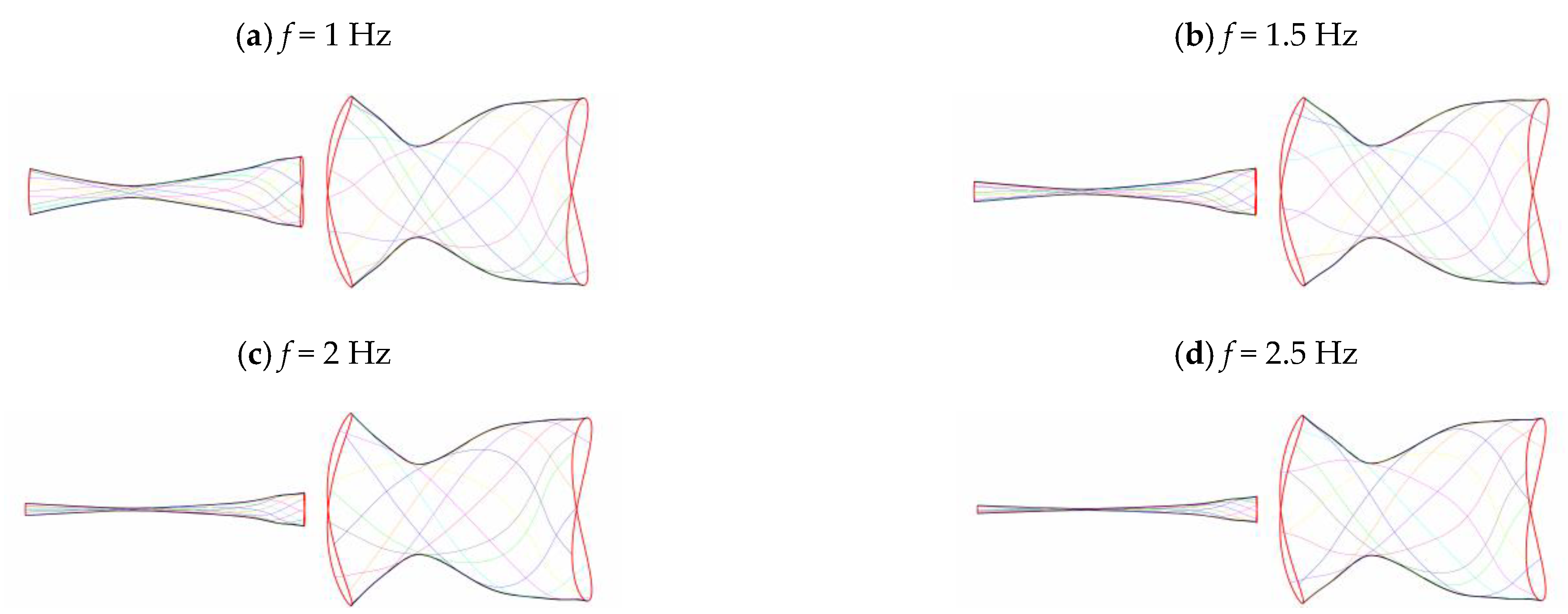
Swimming kinematics with different frequencies are shown in Figure 9. In the case of minimum COT, the amplitude envelopes decreased with frequency. Especially, at 3 Hz–4 Hz, fish relied solely on the tail to generate thrust. However, at the maximum U*, the amplitude envelopes remained the same.
There are other ways to study the frequency effect on swimming performance. For example, in the robotic fish swimming experiment presented in [45], the fishtail is driven by the steering gear. Liu et al. kept the swing angle amplitude of steering gear constant, meaning swimming kinematics do not change. Only the frequency is changed to investigate the swimming performance. Similar to this method, this paper studied the relationships of U*, U’, A*, and COT with frequency while keeping the swing angle of the fishtail (θtail) constant. θtail can be derived based on the different undulatory locomotion of the Pareto fronts. The premise is that these parameters should have a one-to-one mapping with θtail. The relationships of U*, U’, A*, and COT with θtail were checked, and the one-to-one mapping was generally satisfied.
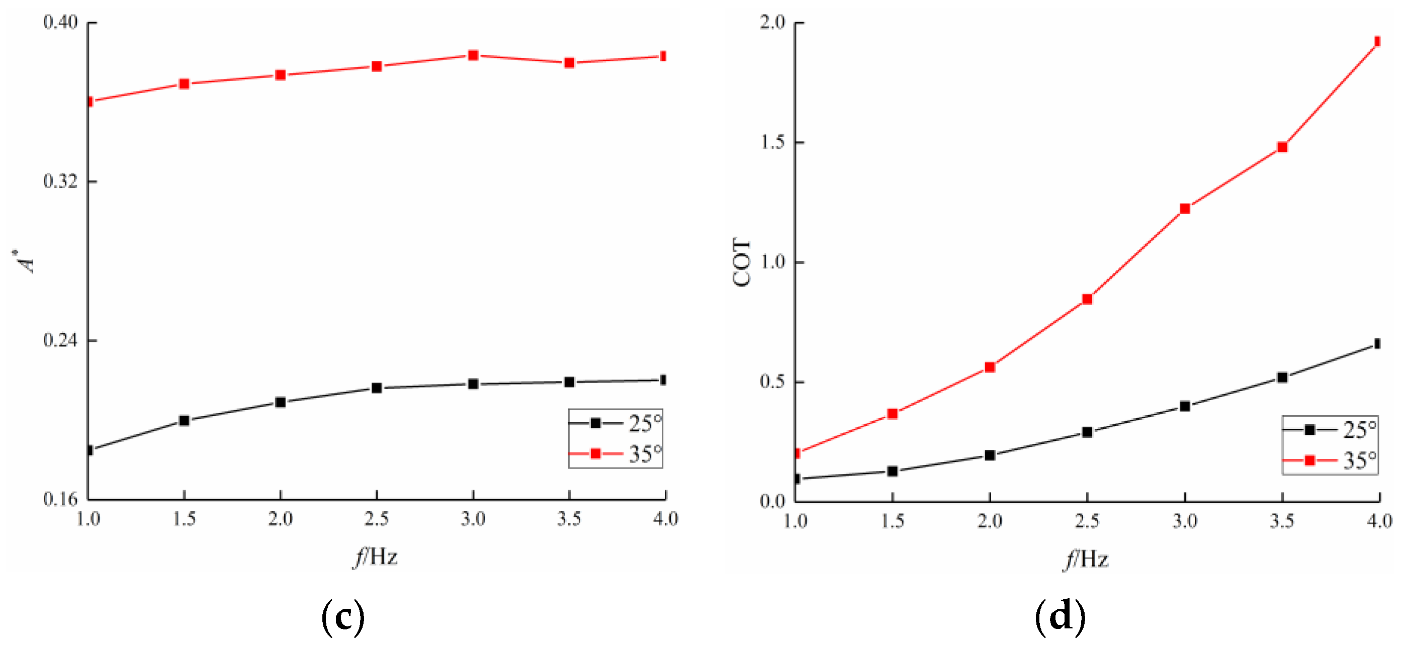
Figure 10 displays the trends of parameters U*, U’, A*, and COT vs. frequency when θtail was 25° and 35°, respectively. U* and COT values showed a sharp increase along with the rise in frequency while U’ and A* values exhibited a lighter increase. This shows that the swimming speed, stride length, and COT are all positively correlated with frequency, which agrees well with the trend of these metrics demonstrated in the experiments of White et al. [29].
Nevertheless, the above simulation result does not mean that the swimming speed increases across the frequency spectrum indefinitely. It is worth noting that the proposed optimization model is suitable for Re within the range of 104 to 106. If Re lies beyond this range, the calculation formula of forces will change, the model will no longer be valid and the relationship between swimming speed and frequency will also change.

3.3. Curvature Amplitude

Figure 11 indicates that as the fish length increased from 0.3 m to 0.7 m, the minimum COT decreased, so the swimming efficiency increased, which is consistent with the optimization results presented in [44]. Two aspects give reason to this occurrence. First, as Kmax decreased with length, the lateral amplitude at the fish head decreased while that at the tail showed a small increase. Moreover, the slope of the amplitude envelope of swimming kinematics became smoother when the length increased (Figure 12). These all led to a reduction in both the recoil motion and the internal diffusion. Furthermore, though U* decreased with length, the actual swimming speed increased with length, leading to an increase in Re. The drag coefficient Cd~Re−0.5 also decreased with length [44].
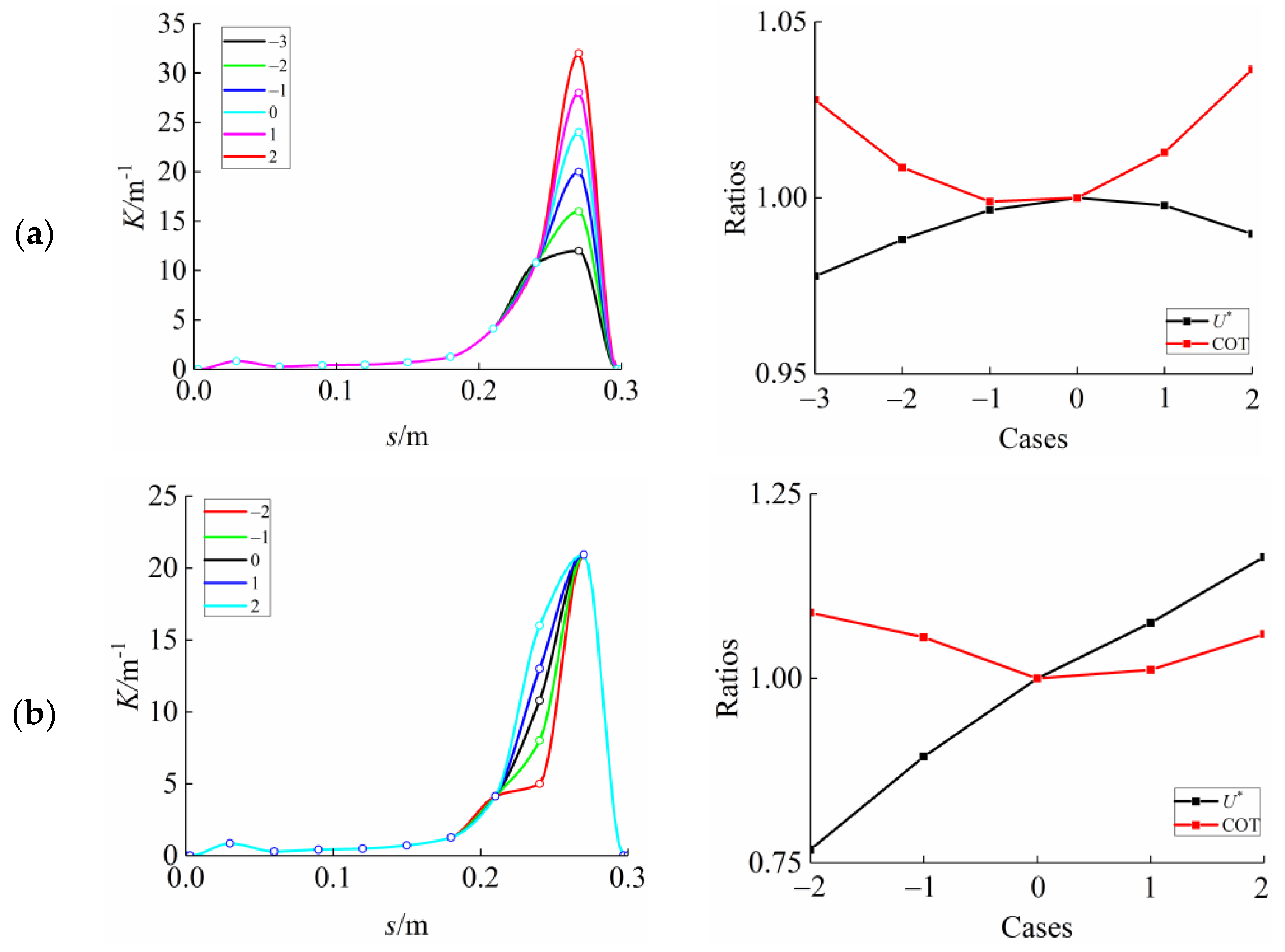
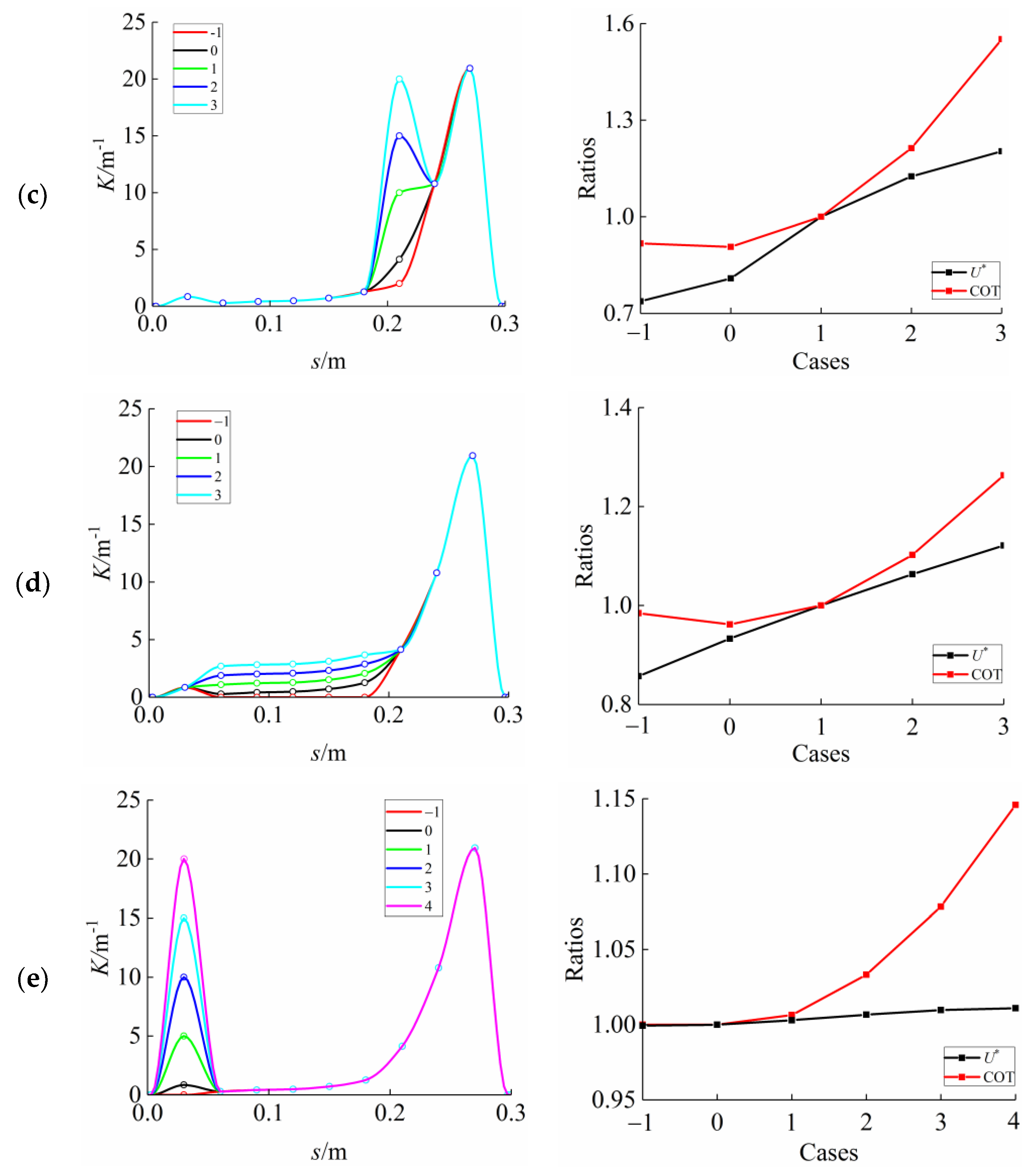
Next, the sensitivity analysis of K(s) was conducted, namely, the impact of varying a single feature of K(s) on swimming performance was studied. As displayed in Figure 6, from the swimming form of high-efficiency A to the swimming form of high-speed F, the values of K at the second, eighth, and ninth interpolation point (represented as K2, K8, K9, respectively) increased at to different extent. On the other hand, the values of K at five interpolation points, from the third one to the seventh one, increased synchronously roughly. Thus, the joint sensitivity analysis of these K values (represented as K3–7) was conducted. To study the influence of Kmax on swimming performance, the K value at the tenth interpolation point (represented as K10) was also included in the discussion. The variations of the aforementioned K values on the swimming performance are shown in Figure 13. For convenience, the curvature amplitudes in the case of minimum COT (Case 0) were a reference for other cases.
K10 was set to 12, 16, 21, 24, 28, and 32 from case −3 to case 2, respectively. K10 appeared to have little effect on the swimming performance, as illustrated in Figure 13a. As K10 increased, both speed and efficiency slightly increased at first and then decreased a little, implying that there must exist some K10 value that maximizes the speed and efficiency. Therefore, although the curvature profile changed from A to F in Figure 6, the value of K10 kept constant. Since the value of K10 affects the swimming performance a little, the restriction of Kmax can be relaxed appropriately.
K9 was set to 5, 8, 10.7, 13, and 16 from case −2 to case 2, respectively (Figure 13b). K9 had a great influence on swimming speed. Higher K9 caused a dramatic improvement (up to 50%) in speed and a small change (up to 10%) in efficiency. In the bi-objective optimization process, case 0, case 1, and case 2 were all non-inferior solutions while both case -2 and case -1 were inferior solutions. Consequently, the minimum K9 illustrated in Figure 6 was the K9 value in case 0.
K8 was set to 2, 4.1, 10, 15, and 20 from case −1 to case 3, respectively (Figure 13c). K8 had a great influence on both speed and efficiency. Higher K8 value resulted in a significant increase in speed and COT, by 62% and 68%, respectively. This change in COT meant that the swimming efficiency was significantly reduced. Therefore, the value of K8 constantly increased from A to F in Figure 6. The second-highest K value, K8, thus became the most important factor in the selection of Kmax. The minimum Kmax value must be higher than that of K8. Considering that the maximum K8 value in Figure 6 was less than 20, Kmax could be relaxed to 6/L.
K3–7 (the average value of the sequence from K3 to K7) was set to 0, 0.6, 1.4, 2.2, and 3 from case −1 to case 3, respectively (Figure 13d). The increase in K3–7 had a similar effect to the increase in K8, leading to a marked rise in speed and COT, by 30% and 26%, respectively. Since the increase in K3–7 was smaller than that of K8, the swimming performance was more sensitive to K3–7.
K2 was set to 0, 0.85, 5, 10, 15, and 20 from case −1 to case 4, respectively (Figure 13e). K2 had little effect on speed. It meant that although K2 increased greatly from A to F in Figure 6, it had little effect on improving the swimming speed. COT increased by 15% along with K2, indicating that the swimming efficiency decreased moderately.

3.4. Comparison among BCF Fish

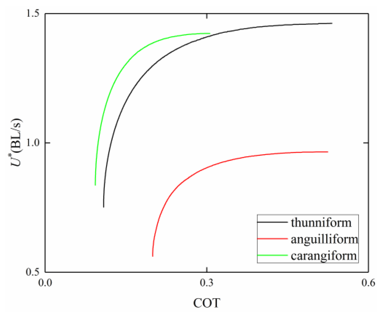
Two other kinds of fishes, anguilliform fish, and thunniform fish, are discussed in this part. The shapes of anguilliform fish and thunniform fish are described in [46] and [33], respectively. Based on the above two body shapes, optimization results of U* and COT are plotted in Figure 14. Interestingly, for the same U*, carangiform fish was more efficient, although thunniform fish is more streamlined in a general sense. This reveals that swimming performance optimization is a comprehensive balance of the body shape, kinematics, dynamics, not just some aspect among them. For the same COT, carangiform fish and thunniform fish were faster than anguilliform fish. The reason is that the caudal fin propulsion adopted by the former two can provide a higher reaction force than the body propulsion used by anguilliform fish.
Portions of different powers included in the total power are plotted in Figure 15, where PD = P// + Pform is the power consumed by the total drag force. Not surprisingly, the change in power ratios of carangiform fish with the swimming speed was in agreement with that of thunniform fish. The greatest difference between anguilliform fish and the other two fishes was that it had a larger P ratio and a small Pm ratio. This indicates that anguilliform fish swimming is mainly a body propulsion mode while carangiform fish and thunniform fish combine body propulsion and caudal fin propulsion. As U* increased, all the elements of PD decreased, while all the elements of P increased. The main cause was that higher values of U* enhanced the lateral motion amplitude of the fish body, bringing about the increase in P. Moreover, with the increase in U*, Pi ratios in thunniform fish and carangiform fish increase rapidly, reaching 66% and 50%, respectively. The Pm ratio in anguilliform fish was about 8%, half that of the ratio in the other two fish types. The reaction force Fm at the tail is often neglected in some related studies of anguilliform fish swimming [17,18,47,48]. Boyer et al. used Poincaré–Cosserat equations to solve the problem of anguilliform fish swimming [48]. Compared to CFD simulation results, the force in the swimming direction is quite different. The omittance of the reaction force may be a factor attributing to this discrepancy.

4. Discussion

Triantafyllou et al. discovered that the St (St = fA/U, f is the tail-beat frequency, A is the peak-to-peak amplitude of the tail) range of swimming animals with foil-like tails is 0.2–0.4 [49]. In our simulation, the St range of carangiform fish was 0.19–0.30 and that of thunniform fish was 0.255–0.360, both of which can be identified for efficient propulsion. However, the St range of anguilliform fish was 0.42–0.5 and was beyond the St range proposed by Triantafyllou et al. On the other hand, Long et al. determined that St equals 0.56 based on the observation data of hagfish swimming and the range calculated by Kern et al. through computational fluid dynamics is 0.59–0.67 [9,50]. Thus, it is considered that the optimal St range, proposed by Triantafyllou et al., may not apply to anguilliform fish swimming.
Moreover, Wiens and Hosoi found that optimally efficient swimming kinematics could be characterized by a non-dimensional variable Ψ (Equations (12) and (13)) [51]. When Ψ is between 0.3 and 1.0, the swimming efficiency is near-optimal. The Ψ range of carangiform fish in this simulation was 0.44–0.94. These analyses reflect the rationality of simulation.
Ψ = 1 sin ( β ) π S t cos ( β ) β π S t
β = π U V S t
where V is the wave propagation speed. U/V is the slip ratio that has been widely used and detailed calculation can be found in previous studies [51,52].
The sensitivity analysis of curvature amplitude showed that K9, K8, and K3–7 were the most significant variables, which can instruct the stiffness adjustment strategy for robotic fish. On the other hand, it can be seen that K2 should always be near zero if the gentle effect on speed is ignored. In other words, there is no need to improve the speed by only one percent at the expense of keeping K2 so large. Following this way, the large curvature amplitudes mainly existed in the last third of the fish body, which conforms to the biological observation in reality. Furthermore, this discovery also reduced the difficulty of the stiffness distribution implementation.
The three differences between our model and Eloy’s model are as follows. First, the frequency was set constant in our model, which can help investigate the frequency effect; second, the fish body shape was determined by the empirical equations. Strange shapes (like Figure 5e,f in [24]) can be avoided through this way; third, COT, the commonly used measure in other references, was chosen as the efficiency measure instead of a novel measure E* first adopted by Eloy. The discussion on the differences between the two efficiency measures is not the scope of this paper. The phenomenon of bifurcation in the Pareto front that ever emerged in Eloy’s model did not occur in our model. The main cause may be the biological fish shape adopted in our model.
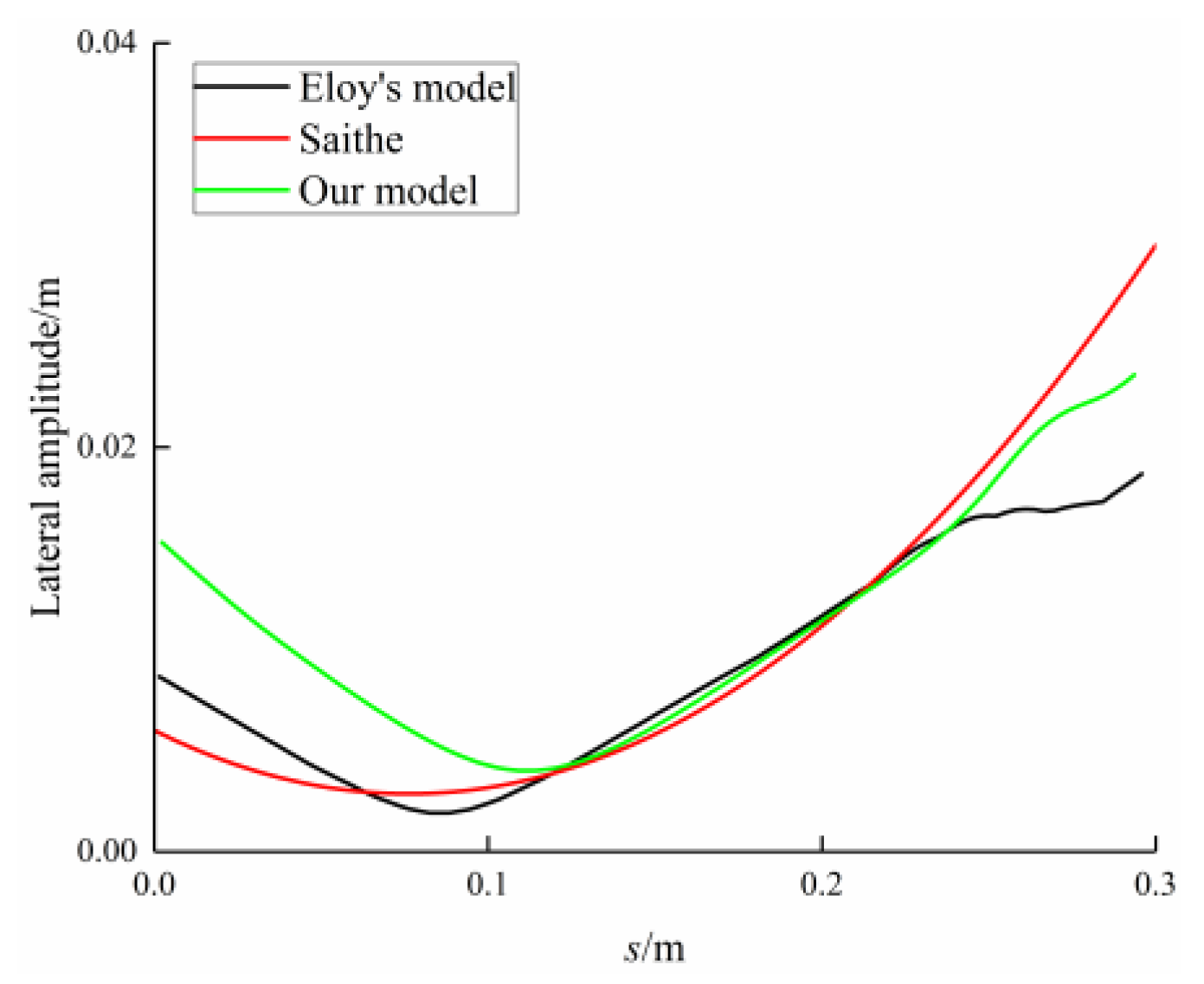
In the case of the highest efficiency, the swimming speed and the midline kinematics obtained by our model are similar to those obtained by Eloy’s model (the relative swimming speed in Eloy’s model is 0.727 and the swimming kinematics are illustrated in Figure 16). The similarity shows that the fish body shape used in our model is near the desired body shape for the most efficient swimming. The midline kinematics of Saithe was also used to make a comparison with the results of these two models (the relevant data is extracted from [53]). The corresponding amplitude envelopes are depicted in Figure 17. There was no big difference between the three cases. The differences in the head and tail amplitudes may result from the fish body shape. It can be concluded that for the most efficient swimming mode, the results obtained from models and the data observed in reality reached an agreement, and the consistency was not only reflected in body shape but also in swimming kinematics.

5. Conclusions

Optimal curvature profiles were obtained by combining bi-objective optimization and the reduced dynamic model proposed by Eloy [24]. As the swimming mode of the carangiform fish transitioned from high-efficiency mode to high-speed mode, the number of local maxima of the curvature amplitude changed from one to three along with the body length.
The frequency effect on swimming performance was examined. The maximum U* and the maximum COT increased linearly with the tail-beat frequency, while the minimum U* and the minimum COT remained constant. On the other hand, when swimming kinematics remained unchanged, swimming speed, stride length, and COT were all positively correlated with the tail-beat frequency.
Based on the sensitivity analysis, the changing mechanism of curvature amplitude regarding swimming speed was revealed. The curvature amplitude at nine-tenths of body length (K10) had little effect on both efficiency and speed. The curvature amplitude at four-fifths of body length (K9) had a great influence on speed but had little effect on efficiency. The curvature amplitude at seven-tenths of body length (K8) and the curvature amplitude between fifths and three-fifths of body length (K3–7) both had a great impact on speed and efficiency. The curvature amplitude at tenths of body length (K2) had little effect on speed, although it increased from high-efficiency mode to high-speed mode. In addition, it was found that the swimming efficiency increased as the fish body was longer.
Optimization in the cases of the other two kinds of BCF fishes (anguilliform fish and thunniform fish) indicated that anguilliform fish mainly adopts body propulsion, while carangiform fish and thunniform fish combine body propulsion and caudal fin propulsion. Portions of different powers included in the total power were analyzed. It was indicated that the lateral motion of anguilliform fish is large and the reaction force of anguilliform fish is low. However, considering that the proportion of the power caused by the reaction force (Pm) of anguilliform fish accounted for about 8%, it is better not to neglect it in the accurate swimming analysis of anguilliform fish.
The above discussion shows that if real-time and accurate curvature control can be achieved, bionic robot fish has the potential to surpass the swimming performance of real fish in terms of swimming efficiency and speed. This study lays a theoretical foundation for the design and control of high-speed and efficient AUVs.

Author Contributions

Conceptualization, Y.L.; methodology, Y.L. and H.J.; formal analysis, Y.L. and H.J.; resources, H.J.; writing—original draft preparation, Y.L.; writing—review and editing, H.J.; supervision, H.J.; project administration, H.J.; funding acquisition, H.J. All authors have read and agreed to the published version of the manuscript.

Funding

This research was funded by the National Natural Science Foundation of China, grant number 51275127.

Institutional Review Board Statement

Not applicable.

Informed Consent Statement

Not applicable.

Data Availability Statement

The numerical and experimental data used to support the findings of this study are included within the article.

Acknowledgments

The authors would like to thank Christophe Eloy from Aix-Marseille University for his technical support.

Conflicts of Interest

The authors declare no conflict of interest.

References

  1. Sfakiotakis, M.; Lane, D.M.; Davies, J.B.C. Review of fish swimming modes for aquatic locomotion. IEEE J. Ocean. Eng. 1999, 24, 237–252. [Google Scholar] [CrossRef] [Green Version]
  2. Lindsey, C. Form, function and locomotory habits in fish. Locomotion 1978. [Google Scholar] [CrossRef]
  3. Wolf, Z.; Jusufi, A.; Vogt, D.; Lauder, G.V. Fish-like aquatic propulsion studied using a pneumatically-actuated soft-robotic model. Bioinspiration Biomim. 2020, 15, 046008. [Google Scholar] [CrossRef]
  4. Bhalla, A.P.S.; Griffith, B.E.; Patankar, N.A. A forced damped oscillation framework for undulatory swimming provides new insights into how propulsion arises in active and passive swimming. PLoS Comput. Biol. 2013, 9, e1003097. [Google Scholar] [CrossRef] [PubMed] [Green Version]
  5. Lauder, G.V. Fish locomotion: Recent advances and new directions. Annu. Rev. Mar. Sci. 2015, 7, 521–545. [Google Scholar] [CrossRef] [PubMed] [Green Version]
  6. Gray, J. Studies in animal locomotion: I. The movement of fish with special reference to the eel. J. Exp. Biol. 1933, 10, 88–104. [Google Scholar] [CrossRef]
  7. Videler, J.J.; Hess, F. Fast continuous swimming of two pelagic predators, saithe (Pollachius virens) and mackerel (Scomber scombrus): A kinematic analysis. J. Exp. Biol. 1984, 109, 209–228. [Google Scholar] [CrossRef]
  8. Gillis, G.B. Environmental effects on undulatory locomotion in the American eel Anguilla rostrata: Kinematics in water and on land. J. Exp. Biol. 1998, 201, 949–961. [Google Scholar] [CrossRef]
  9. Long, J.H.; Koob-Emunds, M.; Sinwell, B.; Koob, T.J. The notochord of hagfish Myxine glutinosa: Visco-elastic properties and mechanical functions during steady swimming. J. Exp. Biol. 2002, 205, 3819–3831. [Google Scholar] [CrossRef]
  10. Wardle, C.; Videler, J.; Altringham, J. Tuning in to fish swimming waves: Body form, swimming mode and muscle function. J. Exp. Biol. 1995, 198, 1629–1636. [Google Scholar] [CrossRef]
  11. Cheng, J.Y.; Blickhan, R. Bending moment distribution along swimming fish. J. Theor. Biol. 1994, 168, 337–348. [Google Scholar] [CrossRef]
  12. Hamlet, C.L.; Hoffman, K.A.; Tytell, E.D.; Fauci, L.J. The role of curvature feedback in the energetics and dynamics of lamprey swimming: A closed-loop model. PLoS Comput. Biol. 2018, 14, e1006324. [Google Scholar] [CrossRef] [PubMed] [Green Version]
  13. Gross, D.; Roux, Y.; Argentina, M. Curvature-based, time delayed feedback as a means for self-propelled swimming. J. Fluids Struct. 2019, 86, 124–134. [Google Scholar] [CrossRef] [Green Version]
  14. Williams, T.L.; McMillen, T. Strategies for swimming: Explorations of the behaviour of a neuro-musculo-mechanical model of the lamprey. Biol. Open 2015, 4, 253–258. [Google Scholar] [CrossRef] [Green Version]
  15. Johnson, T.P.; Syme, D.A.; Jayne, B.C.; Lauder, G.V.; Bennett, A.F. Modeling red muscle power output during steady and unsteady swimming in largemouth bass. Am. J. Physiol. Regul. Integr. Comp. Physiol. 1994, 267, R481–R488. [Google Scholar] [CrossRef] [Green Version]
  16. Curtin, N.; Woledge, R. Efficiency of energy conversion during sinusoidal movement of white muscle fibres from the dogfish Scyliorhinus canicula. J. Exp. Biol. 1993, 183, 137–147. [Google Scholar] [CrossRef]
  17. Jayne, B.; Lauder, G. Red muscle motor patterns during steady swimming in largemouth bass: Effects of speed and correlations with axial kinematics. J. Exp. Biol. 1995, 198, 1575–1587. [Google Scholar] [CrossRef]
  18. Altringham, J.D.; Wardle, C.S.; Smith, C.I. Myotomal muscle function at different locations in the body of a swimming fish. J. Exp. Biol. 1993, 182, 191–206. [Google Scholar] [CrossRef]
  19. Bowtell, G.; Williams, T. Anguilliform body dynamics: Modelling the interaction between muscle activation and body curvature. Philos. Trans. R. Soc. Lond. Ser. B Biol. Sci. 1991, 334, 385–390. [Google Scholar] [CrossRef]
  20. Bowtell, G.; Williams, T.L. Anguilliform body dynamics: A continuum model for the interaction between muscle activation and body curvature. J. Math. Biol. 1994, 32, 83–91. [Google Scholar] [CrossRef]
  21. McMillen, T.; Williams, T.; Holmes, P. Nonlinear muscles, passive viscoelasticity and body taper conspire to create neuromechanical phase lags in anguilliform swimmers. PLoS Comput. Biol. 2008, 4, e1000157. [Google Scholar] [CrossRef] [Green Version]
  22. McMillen, T.; Holmes, P. An elastic rod model for anguilliform swimming. J. Math. Biol. 2006, 53, 843–886. [Google Scholar] [CrossRef]
  23. Van Rees, W.M.; Gazzola, M.; Koumoutsakos, P. Optimal morphokinematics for undulatory swimmers at intermediate Reynolds numbers. J. Fluid Mech. 2015, 775, 178–188. [Google Scholar] [CrossRef] [Green Version]
  24. Eloy, C. On the best design for undulatory swimming. J. Fluid Mech. 2013, 717, 48–89. [Google Scholar] [CrossRef] [Green Version]
  25. Babu, S.P.M.; Sadeghi, A.; Mondini, A.; Mazzolai, B. Antagonistic pneumatic actuators with variable stiffness for soft robotic applications. In Proceedings of the 2019 2nd IEEE International Conference on Soft Robotics (RoboSoft), Seoul, Korea, 14–18 April 2019; pp. 283–288. [Google Scholar]
  26. Li, Y.; Zhou, W.; Cao, Y.; Jia, F. Design of Embedded Structure Variable Stiffness Pneumatic Actuator. In Proceedings of the 2019 International Conference on Intelligent Robotics and Applications (ICIRA), Shenyang, China, 8–11 August 2019; pp. 234–239. [Google Scholar]
  27. Wright, B.; Vogt, D.M.; Wood, R.J.; Jusufi, A. Soft sensors for curvature estimation under water in a soft robotic fish. In Proceedings of the 2019 2nd IEEE International Conference on Soft Robotics (RoboSoft), Seoul, Korea, 14–18 April 2019; pp. 367–371. [Google Scholar]
  28. White, C.; Lauder, G.V.; Bart-Smith, H. Tunabot Flex: A tuna-inspired robot with body flexibility improves high-performance swimming. Bioinspiration Biomim. 2020, 16, 026019. [Google Scholar] [CrossRef] [PubMed]
  29. Zhu, J.; White, C.; Wainwright, D.K.; Di Santo, V.; Lauder, G.V.; Bart-Smith, H. Tuna robotics: A high-frequency experimental platform exploring the performance space of swimming fishes. Sci. Robot. 2019, 4. [Google Scholar] [CrossRef]
  30. Mahl, T.; Hildebrandt, A.; Sawodny, O. A variable curvature continuum kinematics for kinematic control of the bionic handling assistant. IEEE Trans. Robot. 2014, 30, 935–949. [Google Scholar] [CrossRef]
  31. Cheng, H.; Liu, H.; Wang, X.; Liang, B. Approximate Piecewise Constant Curvature Equivalent Model and Their Application to Continuum Robot Configuration Estimation. In Proceedings of the 2020 IEEE International Conference on Systems, Man and Cybernetics (SMC), Toronto, ON, Canada, 11–14 October 2020; pp. 1929–1936. [Google Scholar]
  32. Faulkner, J.; Dirven, S. A generalised, modular, approach for the forward kinematics of continuum soft robots with sections of constant curvature. In Proceedings of the 2017 24th International Conference on Mechatronics and Machine Vision in Practice (M2VIP), Auckland, New Zealand, 21–23 November 2017; pp. 1–6. [Google Scholar]
  33. Valdivia y Alvarado, P.P.A. Design of Biomimetic Compliant Devices for Locomotion in Liquid Environments. Ph.D. Thesis, Massachusetts Institute of Technology, Cambridge, MA, USA, 2007. [Google Scholar]
  34. Cui, Z.; Yang, Z.; Shen, L.; Jiang, H.Z. Complex modal analysis of the movements of swimming fish propelled by body and/or caudal fin. Wave Motion 2018, 78, 83–97. [Google Scholar] [CrossRef]
  35. Lighthill, M.J. Large-amplitude elongated-body theory of fish locomotion. Proc. R. Soc. Lond. Ser. B Biol. Sci. 1971, 179, 125–138. [Google Scholar]
  36. Taylor, G.I. Analysis of the swimming of long and narrow animals. Proc. the R. Soc. Lond. Ser. A Math. Phys. Sci. 1952, 214, 158–183. [Google Scholar]
  37. Hoerner, S.F. Fluid-Dynamic Drag. Theoretical, Experimental and Statistical Information; SF Hoerner Fluid Dynamics: Vancouver, WA, USA, 1965; pp. 108–112. [Google Scholar]
  38. Clarke, A.; Johnston, N.M. Scaling of metabolic rate with body mass and temperature in teleost fish. J. Anim. Ecol. 1999, 68, 893–905. [Google Scholar] [CrossRef]
  39. Webb, P.W. Hydrodynamics and energetics of fish propulsion. Bull. Fish. Res. Board Can. 1975, 190, 1–159. [Google Scholar]
  40. Videler, J.J. Fish Swimming; Springer: Berlin/Heidelberg, Germany, 1993; Volume 10. [Google Scholar]
  41. Gazzola, M.; Van Rees, W.M.; Koumoutsakos, P. C-start: Optimal start of larval fish. J. Fluid Mech. 2012, 698, 5–18. [Google Scholar] [CrossRef] [Green Version]
  42. Deb, K.; Pratap, A.; Agarwal, S.; Meyarivan, T.A.M.T. A fast and elitist multiobjective genetic algorithm: NSGA-II. IEEE Trans. Evol. Comput. 2002, 6, 182–197. [Google Scholar] [CrossRef] [Green Version]
  43. Verma, S.; Hadjidoukas, P.; Wirth, P.; Rossinelli, D.; Koumoutsakos, P. Pareto optimal swimmers. In Proceedings of the 2017 the Platform for Advanced Scientific Computing Conference, Lugano, Switzerland, 26–28 June 2017; pp. 1–11. [Google Scholar]
  44. Tokić, G.; Yue, D.K.P. Optimal shape and motion of undulatory swimming organisms. Proc. R. Soc. B Biol. Sci. 2012, 279, 3065–3074. [Google Scholar] [CrossRef] [Green Version]
  45. Liu, Y.; Jiang, H.; Huang, Q.; Chen, W. Investigation of the Resonant Effect in Carangiform Locomotion. In Proceedings of the 2020 6th International Conference on Mechatronics and Robotics Engineering (ICMRE), Barcelona, Spain, 12–15 February 2020; pp. 58–62. [Google Scholar]
  46. Patel, N.K.; Singh Bhalla, A.P.; Patankar, N.A. A new constraint-based formulation for hydrodynamically resolved computational neuromechanics of swimming animals. J. Comput. Phys. 2018, 375, 684–716. [Google Scholar] [CrossRef]
  47. Boyer, F.; Porez, M.; Leroyer, A. Poincaré–Cosserat equations for the Lighthill three-dimensional large amplitude elongated body theory: Application to robotics. J. Nonlinear Sci. 2010, 20, 47–79. [Google Scholar] [CrossRef] [Green Version]
  48. Candelier, F.; Boyer, F.; Leroyer, A. Three-dimensional extension of Lighthill’s large-amplitude elongated-body theory of fish locomotion. J. Fluid Mech. 2011, 674, 196–226. [Google Scholar] [CrossRef] [Green Version]
  49. Triantafyllou, G.S.; Triantafyllou, M.; Grosenbaugh, M. Optimal thrust development in oscillating foils with application to fish propulsion. J. Fluids Struct. 1993, 7, 205–224. [Google Scholar] [CrossRef]
  50. Kern, S.; Koumoutsakos, P. Simulations of optimized anguilliform swimming. J. Exp. Biol. 2006, 209, 4841–4857. [Google Scholar] [CrossRef] [Green Version]
  51. Wiens, A.; Hosoi, A. Self-similar kinematics among efficient slender swimmers. J. Fluid Mech. 2018, 840, 106–130. [Google Scholar] [CrossRef]
  52. Eloy, C. Optimal Strouhal number for swimming animals. J. Fluids Struct. 2012, 30, 205–218. [Google Scholar] [CrossRef] [Green Version]
  53. Maertens, A.P.; Gao, A.; Triantafyllou, M.S. Optimal undulatory swimming for a single fish-like body and for a pair of interacting swimmers. J. Fluid Mech. 2017, 813, 301–345. [Google Scholar] [CrossRef] [Green Version]
Figure 1. Three main BCF swimming modes. (a) anguilliform mode; (b) carangiform mode; (c) thunniform mode (taken from Lindsey [2]).
Jmse 09 00537 g001
Figure 2. Side view (up) and top view (bottom) of carangiform fish. The shape of carangiform fish is treated as numerous elliptical sections continuously distributed along the spine. a(s) and b(s) mean the major semi-axis and minor semi-axis. s is the arc length and L = 0.3 m is the whole body length.
Jmse 09 00537 g002
Figure 3. The general introduction of the reduced dynamic model proposed by Eloy.
Jmse 09 00537 g003
Figure 4. The flowchart of the NSGA-II algorithm.
Jmse 09 00537 g004
Figure 5. Distributions of τ and φ along the body length. (a) is for the case of minimum COT and (b) is for the case of maximum swimming speed. The average wavelengths of the former and latter cases were 1.17BL and 0.92BL, respectively. All the curves were fitted by piecewise cubic Hermite interpolation.
Jmse 09 00537 g005
Figure 6. The amplitude envelope of curvature profiles of six swimming forms. The circles of (a) represent the discrete points of K(s). (b) shows the swimming speeds and the COT values of the six swimming forms A-F. All the curves of (a) are fitted by piecewise cubic Hermite interpolation. For the different swimming forms A, B, C, D, E, and F, the values of U* were 0.837BL/s, 1.022BL/s, 1.144BL/s, 1.236BL/s, 1.340BL/s, and 1.423BL/s, respectively; the values of COT were 0.093, 0.1, 0.112, 0.129, 0.165, and 0.306, respectively.
Jmse 09 00537 g006
Figure 7. Optimization results of U* and COT at different tail-beat frequencies. The Pareto front remained unchanged after 5000 generations. The corresponding ranges of U* obtained at different frequencies were: [1 Hz: 0.837 BL/s–1.423 BL/s], [1.5 Hz: 0.935 BL/s–2.166 BL/s], [2 Hz: 0.971 BL/s–2.903 BL/s], [2.5 Hz: 0.998 BL/s–3.663 BL/s], [3 Hz: 0.988 BL/s–4.416 BL/s], [3.5 Hz: 1.002 BL/s–5.149 BL/s], [4 Hz: 0.980 BL/s–5.912 BL/s]. The corresponding ranges of COT obtained at different frequencies were: [1 Hz: 0.093–0.306], [1.5 Hz: 0.088–0.492], [2 Hz: 0.087–0.720], [2.5 Hz: 0.087–1.030], [3 Hz: 0.087–1.423], [3.5 Hz: 0.087–1.738], [4 Hz: 0.087–2.260].
Jmse 09 00537 g007
Figure 8. The ranges of U* and COT at different tail-beat frequencies based on the optimization results shown in Figure 7.
Jmse 09 00537 g008
Figure 9. Swimming kinematics at different tail-beat frequencies. (a), (b), (c), (d), (e), (f) and (g) show the swimming kinematics with 1 Hz, 1.5 Hz, 2 Hz, 2.5 Hz, 3 Hz, 3.5 Hz and 4 Hz, respectively. The left side represents cases with the minimum COT and the right side represents cases with the maximum U*. The lines with green, blue, cyan, magenta, yellow, royal, orange, violet, pink, and dark-grey color refer to the swimming kinematics at the t = 0, 0.1 T, 0.2 T, 0.3 T, 0.4 T, 0.5 T, 0.6 T, 0.7 T, 0.8 T, and 0.9 T, respectively. The black line represents the amplitude envelope.
Jmse 09 00537 g009aJmse 09 00537 g009b
Figure 10. U*, U’, A* and COT plotted against the tail-beat frequency, are shown in (a), (b), (c) and (d), respectively. The red and black lines are the cases of θ = 35° and θ = 25°, respectively.
Jmse 09 00537 g010aJmse 09 00537 g010b
Figure 11. Optimization results of U* and COT with different lengths. The dimensions of body geometry, such as a(s) and b(s), are scaled accordingly. When the length was 0.3 m, 0.4 m, 0.5 m, 0.6 m, and 0.7 m, the range of U* was 0.837 BL/s–1.423 BL/s, 0.738 BL/s–1.454 BL/s, 0.644 BL/s–1.462 BL/s, 0.576 BL/s–1.483 BL/s, and 0.518 BL/s–1.486 BL/s, respectively; that of COT was 0.093–0.306, 0.069–0.291, 0.056–0.285, 0.047–0.280, and 0.041–0.290, respectively.
Jmse 09 00537 g011
Figure 12. Amplitude envelopes of swimming kinematics with various lengths based on the optimization results shown in Figure 11.
Jmse 09 00537 g012
Figure 13. Variations of curvature amplitude on the swimming performance U* and COT. (a), (b), (c), (d) and (e) refer to the sensitivity analysis of K10, K9, K8, K3–7 and K2, respectively. The left column is the variation of K(s) at some discrete point and the right column is the effect of this variation on swimming performance.
Jmse 09 00537 g013aJmse 09 00537 g013b
Figure 14. Optimization results of U* and COT of three kinds of fish. In the case of the thunniform fish, the U* range was 0.752 BL/s–1.460 BL/s, and the COT range was 0.1–0.5, which was roughly consistent with the ranges of carangiform fish. In the case of the anguilliform fish, the U* range was 0.562 BL/s–0.965 BL/s, and the COT range was 0.2–0.5.
Jmse 09 00537 g014
Figure 15. The proportion of different powers in the total power as a function of U*. (a), (b) and (c) are the cases of carangiform fish, thunniform fish, and anguilliform fish, respectively. The discrete points in (a) refer to the six swimming forms in Figure 6. The discrete points in (b) and (c) represent the six swimming forms in thunniform fish and anguilliform fish, respectively. Both typical swimming forms are extracted from the Pareto fronts in Figure 14 (the black line and green line in Figure 14).
Jmse 09 00537 g015
Figure 16. The different midline kinematics of carangiform fish. (a) is for the case of the minimum COT in our model; (b) is for the case of the highest efficiency in Eloy’s model; (c) is for the case of Saithe fish in nature through the biological observation.
Jmse 09 00537 g016
Figure 17. The comparison of amplitude envelope among three cases.
Jmse 09 00537 g017
Publisher’s Note: MDPI stays neutral with regard to jurisdictional claims in published maps and institutional affiliations.