
Marine Dual-Fuel Engines Power Smart Management by Hybrid Turbocharging Systems


Abstract
:1. Introduction
2. Materials and Methods
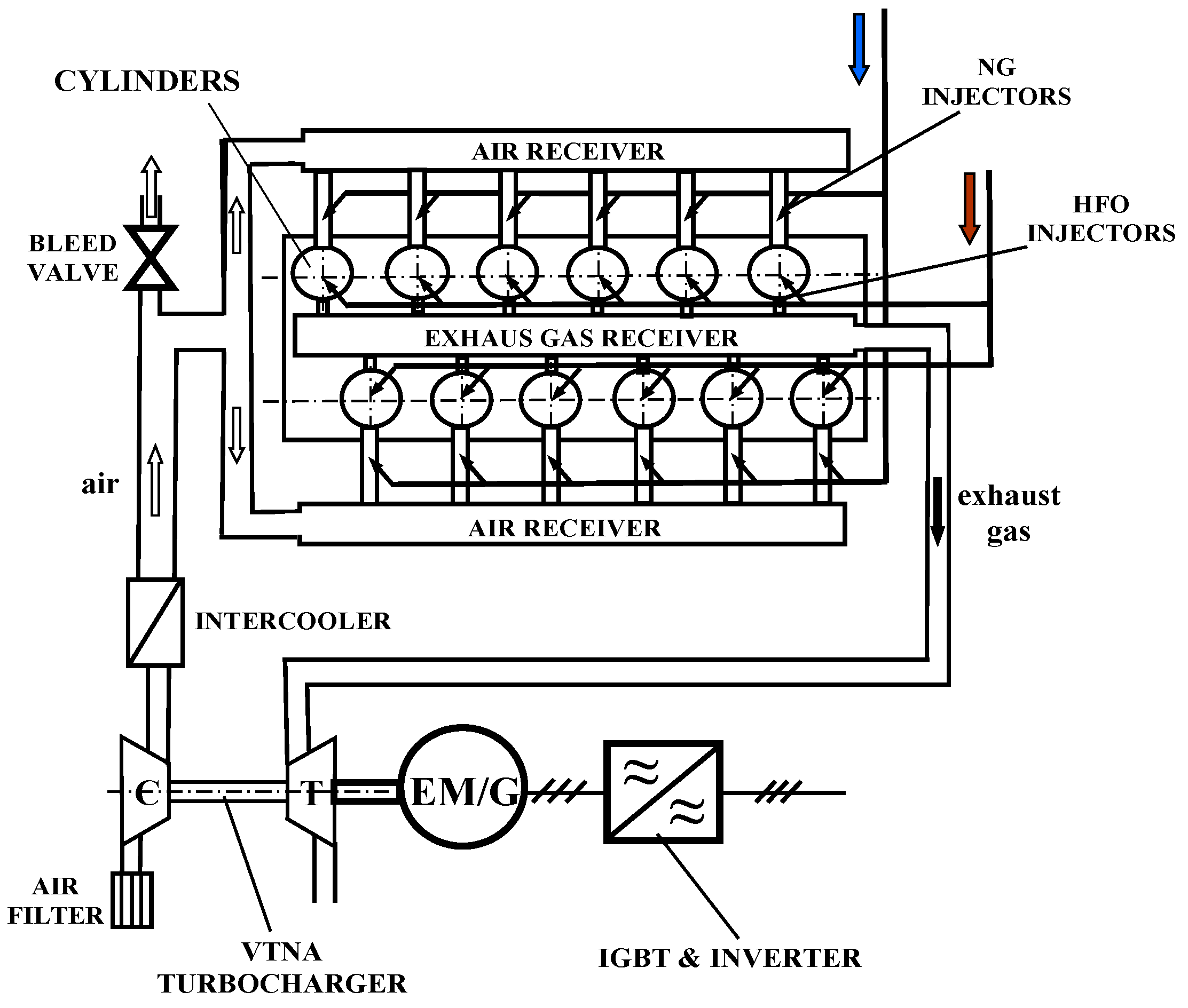
2.1. DF Engines
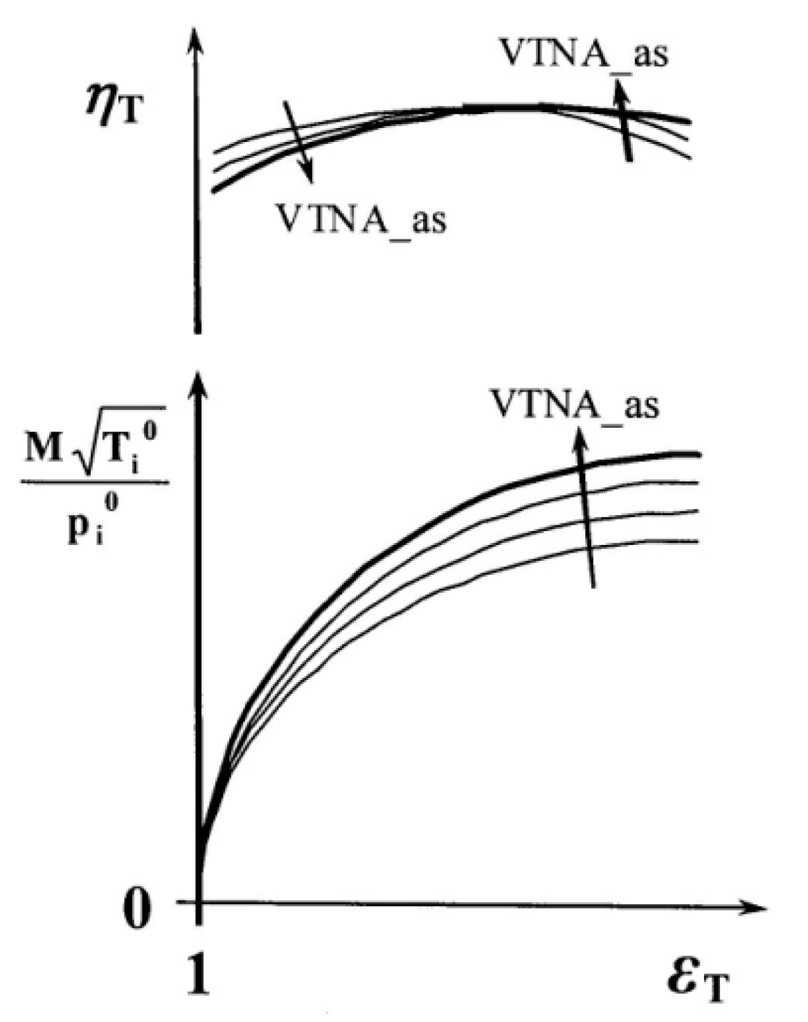
2.2. Hybrid Turbochargers
3. Simulation Case Study
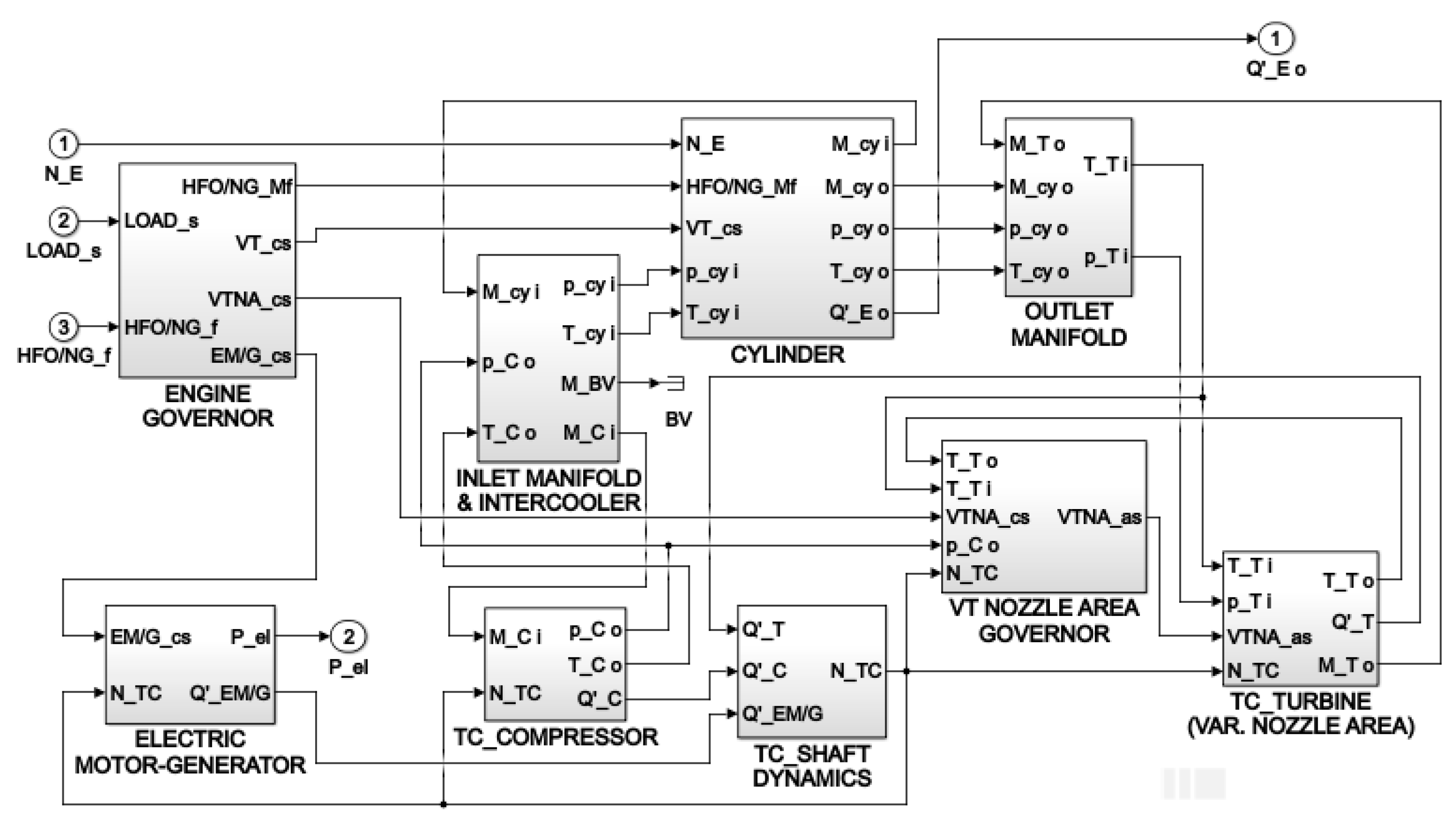
3.1. Numerical Modelling
3.2. Engine Load Control
4. Results and Discussion
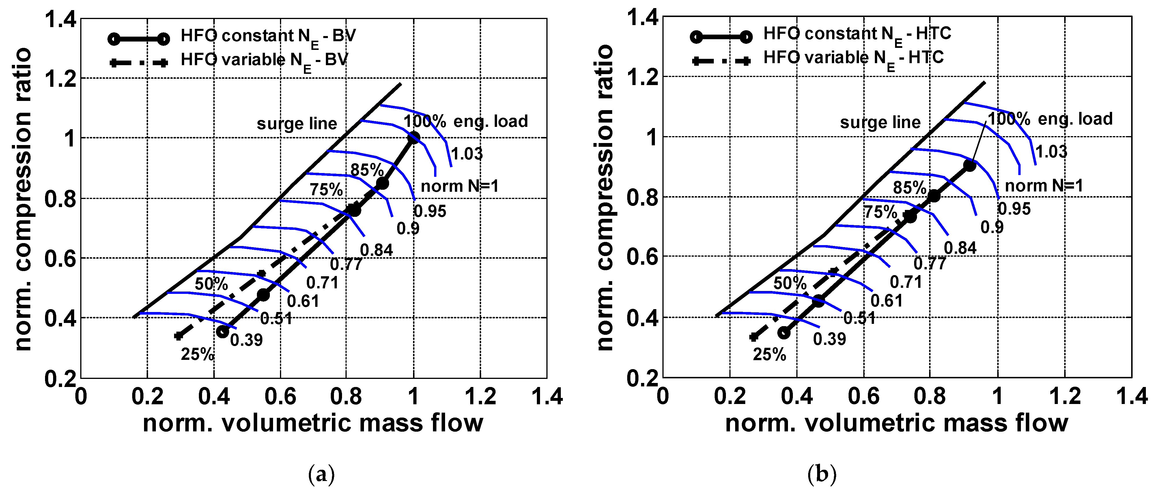
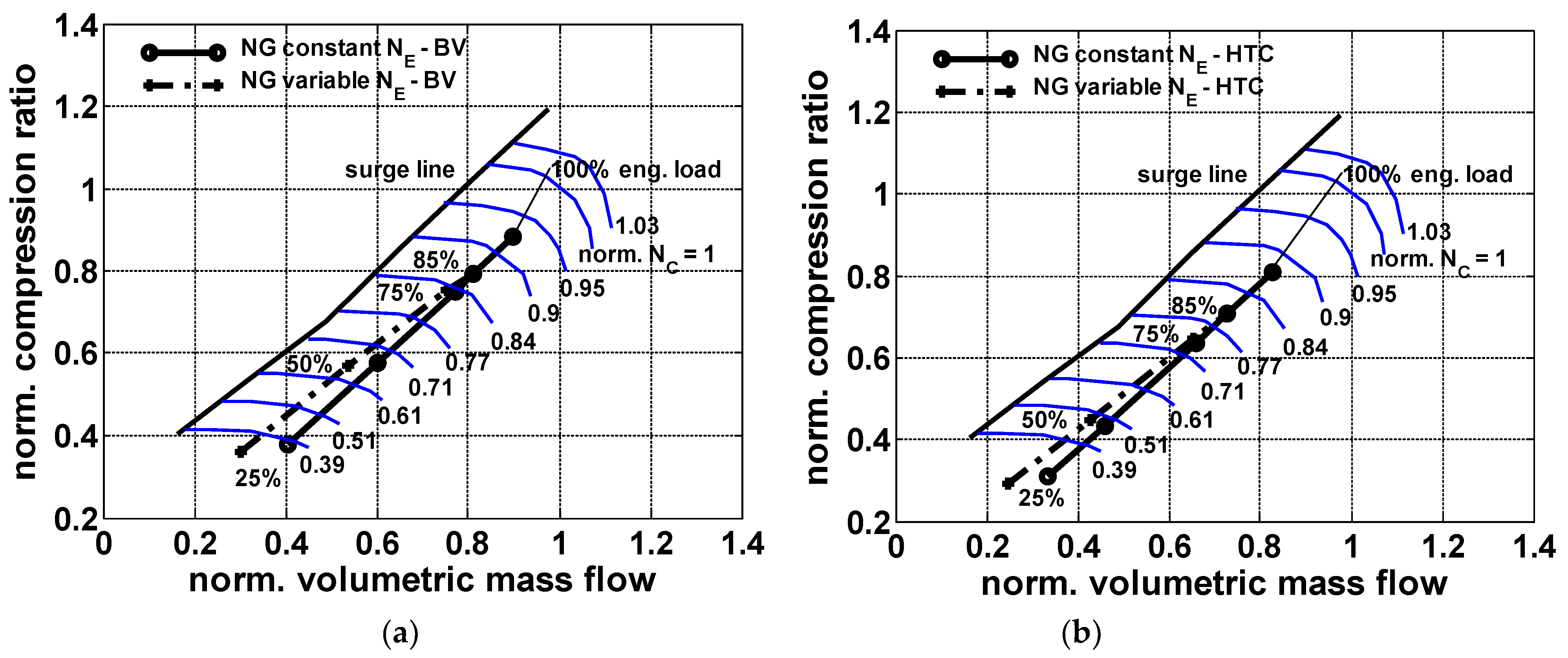
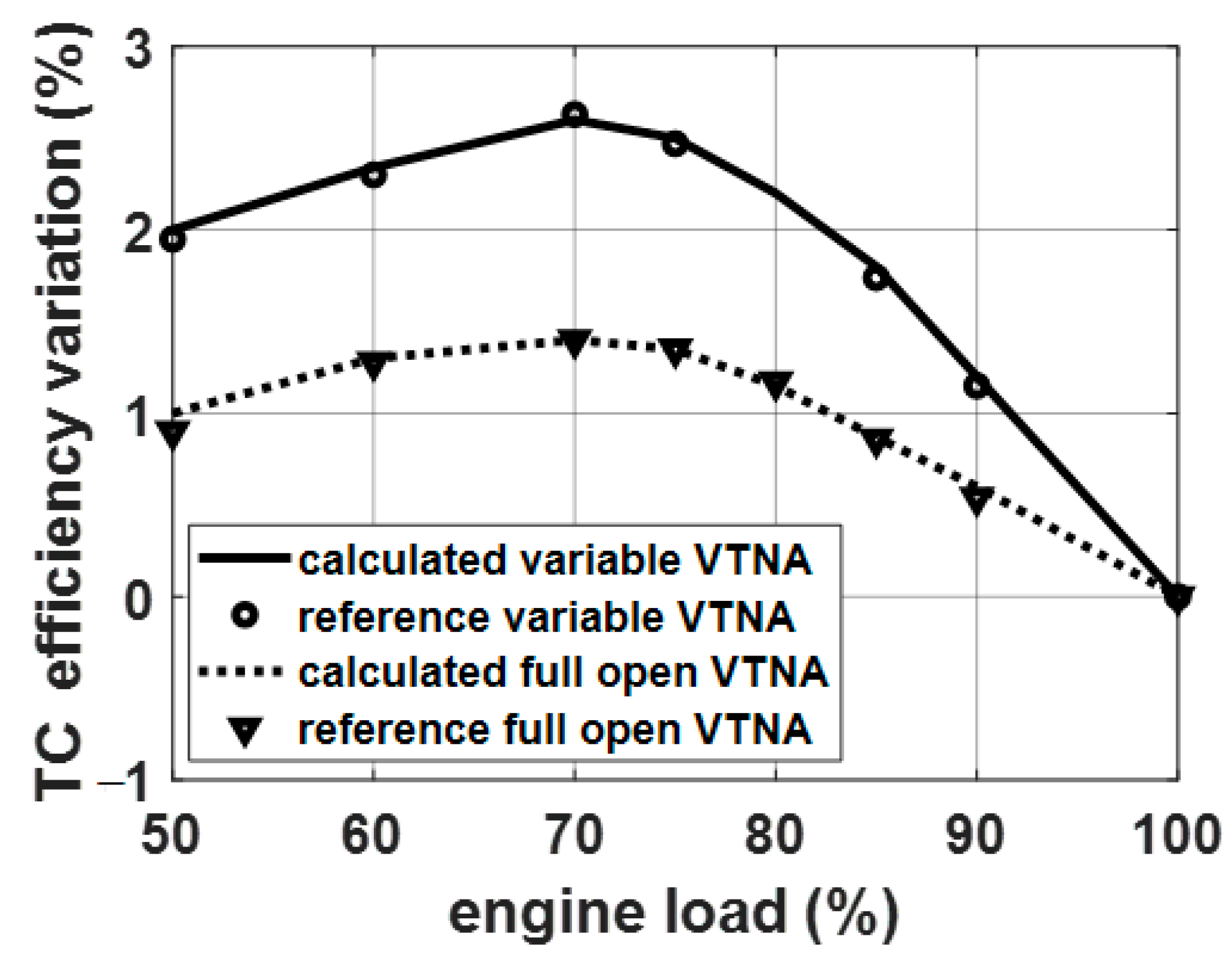
4.1. Turbochargers’ Influence on Engine Performance
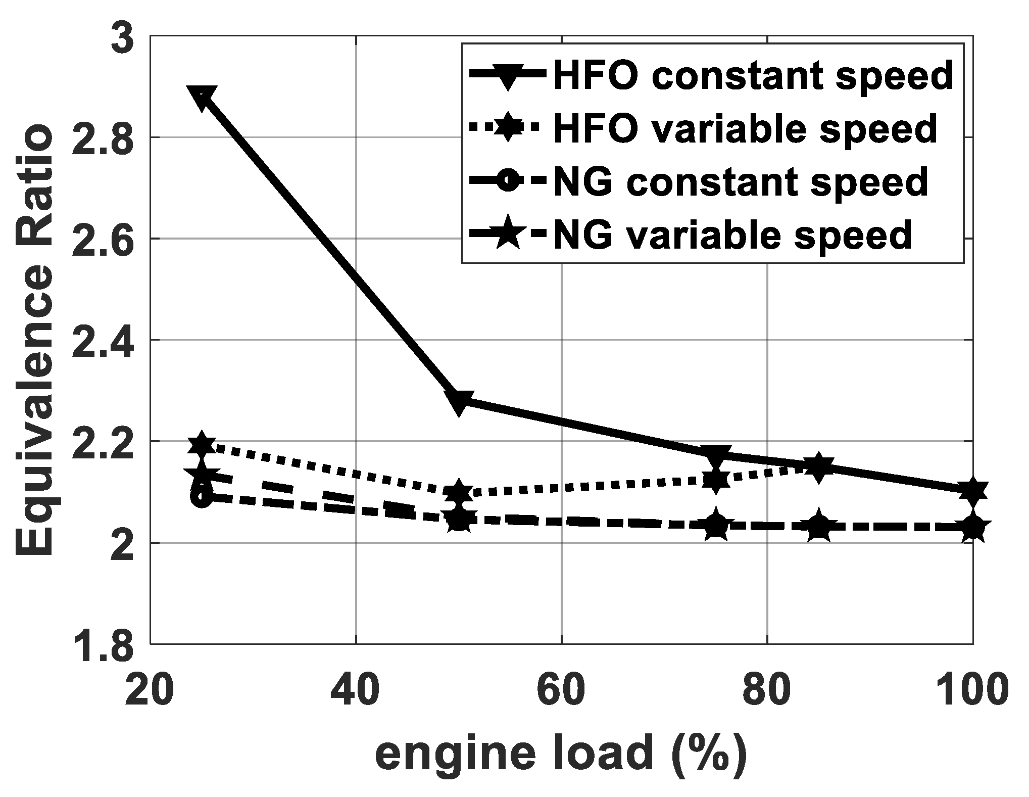
- A greater NG lower heating value, compared to that of HFO (49,000 kJ/kg for NG; 42,700 kJ/kg for HFO);
- A substantial difference of the combustion processes;
- A different equivalence ratio in the cylinders (this last quantity is defined by dividing the AFR value by the stoichiometric ratio).
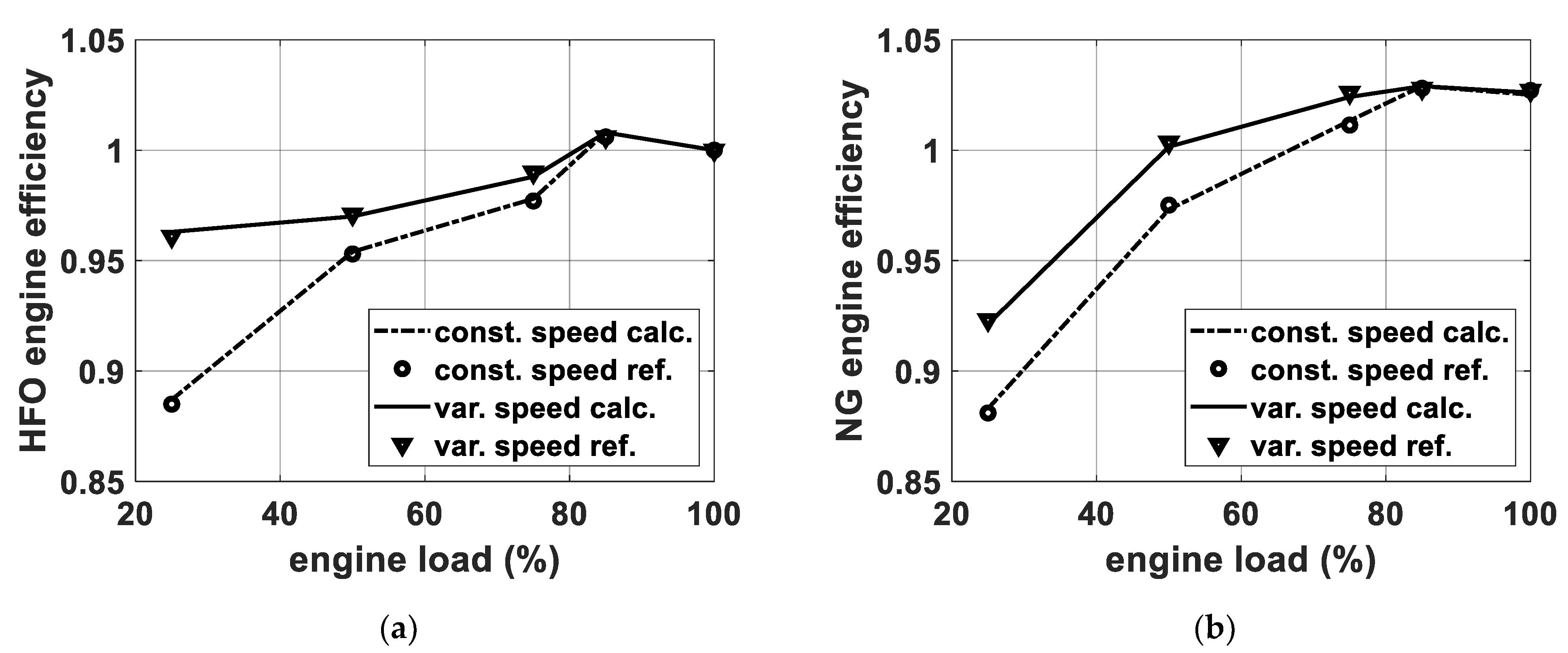
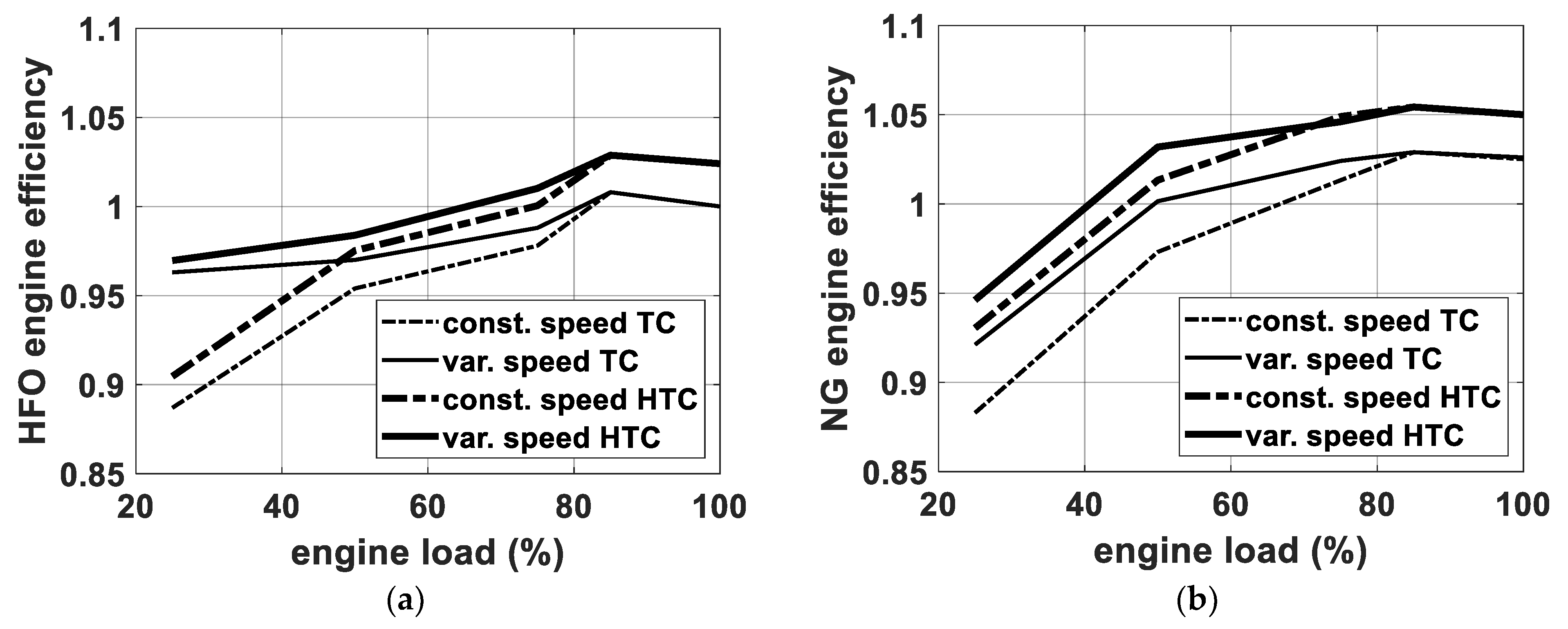
4.2. Turbochargers’ Influence on the Engine Overall Efficiency
5. Conclusions
Author Contributions
Funding
Institutional Review Board Statement
Informed Consent Statement
Data Availability Statement
Acknowledgments
Conflicts of Interest
Nomenclature
| AFR | Air–fuel ratio |
| AR | Aspect ratio |
| b.m.e.p. | Brake mean effective pressure |
| BV | Bleed valve |
| CI | Compression ignition |
| DF | Dual fuel |
| ECA | Emission control areas |
| EEDI | Energy efficiency design index |
| EM/G | Electric motor/generator |
| FLHV | Fuel lower heating value |
| HFO | Heavy fuel oil |
| HTC | Hybrid turbocharger |
| i.m.e.p | Indicated mean effective pressure |
| IMO | International maritime organisation |
| J | Rotor inertia |
| m or M | Mass |
| MCR | Engine Maximum Continuous Rating |
| NG | Natural gas |
| P | Power |
| PI | Positive ignition |
| Q′ | Torque |
| s.f.c. | Specific fuel consumption |
| T | Temperature |
| TC | Turbocharger |
| V | Volume |
| VTNA | Variable turbine nozzle area |
| WGV | Waste gate valve |
| WHR | Waste heat recovery |
| x | Generic variable |
| xb | Fuel mass burned fraction |
| η | Efficiency |
| ω | Angular speed |
| Subscripts | |
| a | Ambient |
| b | Burned |
| BV | Bleed valve |
| C | Compressor |
| E | Engine |
| el | Electric |
| EM/G | Electric motor/generator |
| f | Fuel |
| HTC | Hybrid turbocharger |
| i | Inlet |
| o | Outlet |
| T | Turbine |
| TC | Turbocharger |
| Symbols | |
| EM/G_cs | Electric motor/generator control signal |
| HFO/NG_f | Engine fuel type |
| HFO/NG_Mf | Cylinder fuel mass flow rate |
| LOAD_s | Engine load signal |
| M_BV | Bleed valve mass flow rate |
| M_C i | Compressor inlet mass flow rate |
| M_cy | Cylinder inlet mass flow rate |
| M_cy o | Cylinder outlet mass flow rate |
| M_T o | Turbocharger turbine outlet mass flow rate |
| N_E | Engine speed |
| N_TC | Turbocharger speed |
| p_C o | Compressor outlet pressure |
| p_cy i | Cylinder inlet pressure |
| p_T i | Turbocharger turbine inlet pressure |
| P_el | Electric motor/generator electric power |
| Q′_C | Turbocharger compressor torque |
| Q′_E o | Engine torque |
| Q′_EM/G | Electric motor/generator torque |
| Q′_T | Turbocharger turbine torque |
| T_C o | Compressor outlet temperature |
| T_cy i | Cylinder inlet temperature |
| T_cy o | Cylinder outlet temperature |
| T_T i | Turbocharger turbine inlet temperature |
| T_T o | Turbocharger turbine outlet temperature |
| VT_c | Cylinder valves timing control signal |
| VTNA_as | Turbocharger variable turbine nozzle area actuator signal |
| VTNA_cs | Turbocharger variable turbine nozzle area control signal |
References
- Fan, A.; Wang, J.; He, Y.; Perčić, M.; Vladimir, N.; Yang, L. Decarbonising inland ship power system: Alternative solution and assessment method. Energy 2021, 226, 120266. [Google Scholar] [CrossRef]
- Marine Environment Protection Committee (MEPC). 66th Session, 31 March to 4 April 2014. Available online: https://www.imo.org/en/MediaCentre/MeetingSummaries/Pages/MEPC66.aspx (accessed on 15 June 2021).
- MEPC (Marine Environment Protection Committee). Guidelines to the Method of Calculation of the Attained Energy Efficiency Design Index (EEDI) for New Ships; Resolution, MECP 212 (63/23), ANNEX 8; MEPC: Abingdon, UK, 2012. [Google Scholar]
- IMO. Energy Efficiency Ship Operation, Module 2—Ship Energy Efficiency Regulation and Related Guidelines; IMO: London, UK, 2016. [Google Scholar]
- Ioannidis, J. Waste heat recovery from Diesel engines. In Proceedings of the 3rd International Congress of International Maritime Association of the East Mediterranean (IMAEM), Athens, Greece, 28 May–1 June 1984. [Google Scholar]
- Ito, K.; Akagi, S. An optimal planning method for a marine heat and power generation plant by considering its operational problem. Energy Res. 2007, 10, 75–85. [Google Scholar] [CrossRef]
- Theotokatos, G.; Livanos, G.A. Exhaust gas waste heat recovery in marine propulsion plants. In Proceedings of the 14th Conference on International Maritime Association of Mediterranean (IMAM), Genova, Italy, 13–16 September 2011. [Google Scholar]
- Byung, C.C.; Young, M.K. Thermodynamic analysis of a dual loop heat recovery system with trilateral cycle applied to exhaust gases of internal combustion engine for propulsion of the 6800 TEU container ship. Energy 2013, 58, 404–416. [Google Scholar]
- Altosole, M.; Benvenuto, G.; Campora, U.; Laviola, M.; Trucco, A. Waste heat recovery from marine gas turbines and diesel engines. Energies 2017, 10, 718. [Google Scholar] [CrossRef] [Green Version]
- Barone, G.; Buonomano, A.; Forzano, C.; Palombo, A.; Vicidomini, M. Sustainable energy design of cruise ships through dynamic simulations: Multi-objective optimization for waste heat recovery. Energy Convers. Manag. 2020, 221, 113166. [Google Scholar] [CrossRef]
- Livanos, G.A.; Theotokatos, G.; Patagonis, D.N. Techno-economical investigation of alternative propulsion plant for ferries and roro ships. Energy Convers. Manag. 2014, 79, 640–651. [Google Scholar] [CrossRef] [Green Version]
- Altosole, M.; Campora, U.; Donnarumma, S.; Zaccone, R. Simulation techniques for design and control of a waste heat recovery system in marine natural gas propulsion applications. J. Mar. Sci. Eng. 2019, 7, 397. [Google Scholar] [CrossRef] [Green Version]
- Altosole, M.; Benvenuto, G.; Zaccone, R.; Campora, U. Comparison of saturated and superheated steam plants for waste-heat recovery of dual-fuel marine engines. Energies 2020, 13, 985. [Google Scholar] [CrossRef] [Green Version]
- Altosole, M.; Benvenuto, G.; Campora, U.; Laviola, M.; Zaccone, R. Simulation and performance comparison between diesel and natural gas engines for marine applications. J. Eng. Marit. Environ. 2017, 231, 690–704. [Google Scholar] [CrossRef]
- Yoshihisa, O.; Keiichi, S.; Yukio, Y. Application of a large hybrid turbocharger for marine electric-power generation. Mitsubishi Heavy Ind. Tech. Rev. 2012, 49, 29. [Google Scholar]
- Keiichi, S.; Yoshihisa, O.; Yukio, Y.; Musashi, S. Energy Savings Through Electric-Assist Turbocharger for Marine Diesel Engines. Mitsubishi Heavy Ind. Tech. Rev. 2015, 52, 36–41. [Google Scholar]
- Alshammari, M.; Alshammari, F.; Pesyridis, A. Electric Boosting and Energy Recovery Systems for Engine Downsizing. Energies 2019, 12, 4636. [Google Scholar] [CrossRef] [Green Version]
- Dong, H.; Zhao, Z.; Fu, J.; Liu, J.; Li, J.; Liang, K.; Zhou, Q. Experiment and simulation investigation on energy management of a gasoline vehicle and hybrid turbocharger optimization based on equivalent consumption minimization strategy. Energy Convers. Manag. 2020, 226, 113518. [Google Scholar] [CrossRef]
- Metz, D.; Werner, J.; Münz, S.; Becker, M. Charging system for fuel cell applications. MTZ Worldw. 2013, 74, 40–43. [Google Scholar] [CrossRef]
- Rusman, J.D. Charge air configurations for propulsion diesel engines aboard fast naval combatants. In Proceedings of the 14th International Naval Engineering Conference & Exhibition (INEC), Glasgow, UK, 2–4 October 2018. [Google Scholar]
- Altosole, M.; Benvenuto, G.; Campora, U.; Silvestro, F.; Terlizzi, G. Efficiency improvement of a natural gas marine engine using a hybrid turbocharger. Energies 2018, 11, 1924. [Google Scholar] [CrossRef] [Green Version]
- Geertsma, R.D.; Negenborn, R.R.; Visser, K.; Hopman, J.J. Design and control of hybrid power and propulsion systems for smart ships: A review of developments. Appl. Energy 2017, 194, 30–54. [Google Scholar] [CrossRef]
- Coppola, T.; Micoli, L.; Turco, M. State of the art of high temperature fuel cells in maritime applications. In Proceedings of the International Symposium on Power Electronics, Electrical Drives, Automation and Motion, Sorrento, Italy, 24–26 June 2020; pp. 430–435. [Google Scholar]
- Sapra, H.; Stam, J.; Reurings, J.; van Biert, L.; van Sluijs, W.; de Vos, P.; Visser, K.; Vellayani, A.P.; Hopman, H. Integration of solid oxide fuel cell and internal combustion engine for maritime applications. Appl. Energy 2021, 281, 115854. [Google Scholar] [CrossRef]
- Geertsma, R.D.; Negenborn, R.R.; Visser, K.; Hopman, J.J. Parallel Control for Hybrid Propulsion of Multifunction Ships. IFAC-Pap. Line 2017, 50, 2296–2303. [Google Scholar] [CrossRef]
- Capasso, C.; Veneri, O.; Notti, E.; Sala, A.; Figari, M.; Martelli, M. Preliminary design of the hybrid propulsion architecture for the research vessel “G. Dallaporta”. In Proceedings of the International Conference on Electrical Systems for Aircraft, Railway, Ship Propulsion and Road Vehicles & International Transportation Electrification Conference, Toulouse, France, 2–4 November 2016. [Google Scholar]
- Altosole, M.; Campora, U.; Vigna, V. Energy efficiency analysis of a flexible marine hybrid propulsion system. In Proceedings of the International Symposium on Power Electronics, Electrical Drives, Automation and Motion, Sorrento, Italy, 24–26 June 2020; pp. 436–441. [Google Scholar]
- Mauro, F.; Ghigliossi, E.; Bucci, V.; Marinó, A. Design of hybrid-electric megayachts: The impact of operative profile and smart berthing infrastructures. J. Mar. Sci. Eng. 2021, 9, 186. [Google Scholar] [CrossRef]
- Feneley, A.J.; Pesiridis, A.; Andwari, A.M. Variable Geometry Turbocharger Technologies for Exhaust Energy Recovery and boosting-A Review. Renew. Sustain. Energy Rev. 2017, 71, 959–975. [Google Scholar] [CrossRef]
- Woodyard, D. Pounder’s Marine Diesel Engines and Gas, 9th ed.; Elsevier Ltd.: Oxford, UK, 2009. [Google Scholar]
- MAN 51/60 DF IMO TIER II/IMO TIER III Marine Project Guide; MAN: Munich, Germany, 2015.
- Benvenuto, G.; Campora, U.; Laviola, M.; Terlizzi, G. Simulation model of a dual-fuel four stroke engine for low emission ship propulsion applications. Int. Rev. Mech. Eng. 2017, 11, 817–882. [Google Scholar] [CrossRef]
- Benvenuto, G.; Campora, U.; Carrera, G.; Casoli, P. A two-zone Diesel engine model for the simulation of marine propulsion plant transients. In Proceedings of the MARIND 98, Second International Conference on Marine Industry, Varna, Bulgaria, 28 September–2 October 1998. [Google Scholar]
- Theotokatos, G.; Stoumpos, S.; Lazakis, I.; Livanos, G. Numerical study of a marine dual-fuel four-stroke engine. Marit. Technol. Eng. 3 2016, 2, 777–786. [Google Scholar]
- Tadros, M.; Ventura, M.; Guedes Soares, C. Data driven in-cylinder pressure diagram based optimization procedure. J. Mar. Sci. Eng. 2020, 8, 294. [Google Scholar] [CrossRef] [Green Version]
- Mrzljak, V.; Medica, V.; Bukovac, O. Quasi-dimensional diesel engine model with direct calculation of cylinder temperature and pressure. Technical Gazette 2017, 24, 681–686. [Google Scholar]
- Altosole, M.; Campora, U.; Figari, M.; Laviola, M.; Martelli, M. A diesel engine modelling approach for ship propulsion real-time simulators. J. Mar. Sci. Eng. 2019, 7, 138. [Google Scholar] [CrossRef] [Green Version]
- Tavakoli, S.; Saettone, S.; Steen, S.; Andersen, P.; Schramm, J.; Pedersen, E. Modeling and analysis of performance and emissions of marine lean-burn natural gas engine propulsion in waves. Appl. Energy 2020, 279, 115904. [Google Scholar] [CrossRef]
- Tadros, M.; Ventura, M.; Guedes Soares, C. Simulation of the performance of marine genset based on double-wiebe function. Sustainable Development and Innovations in Marine Technologies. In Proceedings of the 18th International Congress of the International Maritime Association of the Mediterranean, IMAM, Varna, Bulgaria, 9–11 September 2019; pp. 292–299. [Google Scholar]
- MAN. VTA—Variable Turbine Area. MAN Diesel & Turbo Report; MAN: Munich, Germany, 2010. [Google Scholar]


| MAN 51-60 DF 12V | HFO/NG |
|---|---|
| engine length (mm) | 10,254 |
| height (mm) | 5517 |
| width (mm) | 4713 |
| dry weight (t) | 189 |
| cylinders number | 12V |
| bore (mm) | 510 |
| stroke (mm) | 600 |
| fuel type | HFO/NG |
| brake power (kW) | 12,000 |
| speed (rpm) | 514 |
| b.m.e.p. (bar) | 19.1 |
| s.f.c. (g/kWh) | 189/157 |
| charge air pressure (barg) | 4.29/3.77 |
| Delivered Engine Power | Results at Constant Engine Speed (514 rpm): Without Brackets | |||||||||
|---|---|---|---|---|---|---|---|---|---|---|
| Results at Variable Engine Speed: In Brackets [ ] | ||||||||||
| % (rpm) | s.f.c | Co Air Mass Flow | Charge Air pr. | Co Temp. | To Temp. | |||||
| HFO | NG | HFO | NG | HFO | NG | HFO | NG | HFO | NG | |
| 100 (514 rpm) | 0.21 | 0.49 | 0.06 | 0.32 | 0.12 | −0.23 | 1.37 | 0.46 | 0.00 | 1.05 |
| [0.17] | [0.36] | [−0.11] | [0.21] | [0.08] | [0.07] | [−0.56] | [0.18] | [−0.32] | [0.82] | |
| 85 (514 rpm) | −0.79 | −0.57 | −2.18 | 0.78 | −0.48 | 1.02 | −1.03 | 0.01 | 1.23 | 1.36 |
| [−0.65] | [−0.46] | [1.82] | [0.85] | [−0.36] | [0.74] | [1.08] | [0.02] | [1.15] | [0.93] | |
| 75 (501 rpm) | 0.29 | −0.45 | −0.97 | −1.52 | −1.97 | 2.21 | −1.23 | 0.00 | 0.87 | 1.39 |
| [−0.31] | [−0.48] | [−0.45] | [−1.08] | [−2.04] | [1.51] | [1.74] | [0.02] | [−1.06] | [1.78] | |
| 50 (442 rpm) | −0.19 | 0.24 | 0.31 | −0.65 | −1.21 | 1.52 | −1.42 | 1.38 | −2.11 | 2.42 |
| [0.43] | (0.71] | [−0.19] | [−1.02] | [−0.84] | [1.03] | [1.05] | [1.53] | [−1.73] | [1.67] | |
| 25 (402 rpm) | −1.01 | −0.34 | _ | _ | _ | _ | _ | _ | _ | _ |
| [−0.67] | [−0.43] | |||||||||
| Line | Engine Parameters | Engine Loads and Fuel Type | |||||||||
|---|---|---|---|---|---|---|---|---|---|---|---|
| 1 | Engine power (%) | 100 | 85 | 75 | 50 | 25 | |||||
| 2 | Engine power (kW) | 12,000 | 10,260 | 9000 | 6000 | 3000 | |||||
| 3 | Engine speed (rpm) | 514 | 514 | 514 | 514 | 514 | |||||
| 4 | Fuel type | HFO | NG | HFO | NG | HFO | NG | HFO | NG | HFO | NG |
| 5 | EM/G electric power (kW) | 526 | 498 | 426 | 551 | 320 | 671 | 203 | 562 | 87 | 351 |
| 6 | EM/G electric power (%) | 4.38 | 4.15 | 4.15 | 5.37 | 3.55 | 7.45 | 3.38 | 9.37 | 2.91 | 11.70 |
| 7 | Turbocharger speed (Δ%) | −5.29 | −4.86 | −5.81 | −7.51 | −4.88 | −10.97 | −11.31 | −28.41 | −10.52 | −23.68 |
| 8 | Air compression ratio (Δ%) | −9.73 | −7.70 | −5.72 | −10.95 | −3.64 | −15.15 | −5.34 | −24.79 | −1.37 | −17.69 |
| 9 | Compressor temperature (Δ%) | −3.26 | −3.85 | −2.84 | −4.44 | −2.09 | −5.46 | −3.13 | −6.52 | −1.43 | −6.89 |
| 10 | Compressor air flow rate (Δ%) | −8.19 | −7.70 | −10.53 | −10.31 | −10.03 | −14.47 | −15.23 | −22.70 | −14.68 | −16.95 |
| 11 | Compressor efficiency (Δ%) | 2.09 | −0.12 | 1.65 | 0.65 | 1.86 | 1.60 | 1.21 | 0.97 | 2.68 | 1.06 |
| 12 | Cylinder air flow rate (Δ%) | 0.06 | 0.01 | −0.18 | −0.01 | −0.31 | 0.01 | 0.03 | 0.01 | 0.08 | 0.01 |
| 13 | Cylinder air temperature (Δ%) | −0.29 | −0.51 | −0.25 | −0.68 | −0.23 | −0.61 | −0.06 | −0.29 | −0.07 | −0.79 |
| 14 | Cylinder exhaust gas flow (Δ%) | 0.06 | 0.01 | −0.18 | 0.02 | −0.32 | 0.01 | 0.04 | 0.02 | 0.08 | 0.02 |
| 15 | Turbine expansion ratio (Δ%) | −0.03 | 0.22 | −0.51 | 1.17 | −0.24 | 0.58 | −0.17 | 2.62 | −0.15 | 5.42 |
| 16 | Turbine inlet pressure (Δ%) | −0.03 | 0.21 | −0.18 | 0.39 | −0.28 | 0.61 | −0.22 | 0.25 | 0.07 | 0.32 |
| 17 | Turbine inlet temperature (Δ%) | −0.11 | −0.12 | 0.10 | −0.17 | 0.18 | −0.34 | −0.07 | −0.21 | −0.06 | −0.58 |
| 18 | Turbine outlet temperature (Δ%) | −0.10 | −0.11 | 0.13 | −0.14 | −0.21 | −0.27 | −0.01 | −0.10 | −0.05 | −0.24 |
| 19 | Turbine efficiency (Δ%) | 0.00 | 0.00 | 0.00 | 0.01 | 0.01 | 0.01 | −0.01 | −0.01 | −0.01 | 0.01 |
| 20 | Engine i.m.e.p. (Δ%) | 0.02 | −0.02 | −0.01 | −0.02 | −0.01 | −0.03 | 0.03 | −0.01 | 0.00 | −0.02 |
| Line | Engine Parameters | Engine Loads and Fuel Type | |||||||||
|---|---|---|---|---|---|---|---|---|---|---|---|
| 1 | Engine power (%) | 100 | 85 | 75 | 50 | 25 | |||||
| 2 | Engine power (kW) | 12,000 | 10,260 | 9000 | 6000 | 3000 | |||||
| 3 | Engine speed (rpm) | 514 | 514 | 501 | 462 | 402 | |||||
| 4 | Fuel type | HFO | NG | HFO | NG | HFO | NG | HFO | NG | HFO | NG |
| 5 | EM/G electric power (kW) | 526 | 498 | 426 | 551 | 293 | 571 | 98 | 576 | 27 | 226 |
| 6 | EM/G electric power (%) | 4.38 | 4.15 | 4.15 | 5.37 | 3.25 | 6.34 | 1.63 | 9.60 | 0.90 | 7.53 |
| 7 | Turbocharger speed (Δ%) | −5.29 | −4.86 | −5.81 | −7.51 | −3.59 | −11.85 | −22.21 | −29.12 | −17.15 | −21.36 |
| 8 | Air compression ratio (Δ%) | −9.73 | −8.19 | −5.72 | −10.95 | −3.84 | −14.11 | −3.17 | −21.69 | −1.15 | −18.68 |
| 9 | Compressor temperature (Δ%) | −3.26 | −3.85 | −2.84 | −4.44 | −1.92 | −5.46 | −1.23 | −6.52 | −0.61 | −6.89 |
| 10 | Compressor airflow rate (Δ%) | −8.19 | −7.70 | −10.53 | −10.31 | −7.41 | −13.27 | −7.34 | −20.66 | −6.89 | −17.95 |
| 11 | Compressor efficiency (Δ%) | 2.09 | 0.12 | 1.65 | 0.65 | 2.21 | 1.71 | 2.44 | 1.29 | 1.09 | 2.02 |
| 12 | Cylinder airflow rate (Δ%) | 0.06 | 0.01 | −0.18 | 0.02 | 0.24 | 0.01 | −019 | −0.01 | −0.23 | 0.01 |
| 13 | Cylinder air temperature (Δ%) | −0.29 | −0.55 | −0.25 | −0.63 | −0.19 | −0.59 | −0.14 | −0.43 | −0.02 | −0.66 |
| 14 | Cylinder exhaust gas flow (Δ%) | 0.06 | 0.01 | −0.18 | −0.01 | 0.23 | 0.01 | −0.20 | −0.01 | −0.23 | 0.02 |
| 15 | Turbine expansion ratio (Δ%) | −0.03 | 0.21 | −0.51 | 1.18 | −0.49 | 0.58 | −0.22 | 2.43 | 0.00 | 3.29 |
| 16 | Turbine inlet pressure (Δ%) | −0.03 | 0.22 | −0.18 | 0.16 | −0.04 | 0.53 | −0.17 | 0.34 | −0.08 | 0.27 |
| 17 | Turbine inlet temperature (Δ%) | −0.11 | −0.14 | 0.10 | −0.16 | −0.23 | −0.39 | 0.08 | −0.26 | 0.12 | −0.45 |
| 18 | Turbine outlet temperature (Δ%) | −0.10 | −0.11 | 0.13 | −0.14 | −0.19 | 0.26 | 0.11 | 0.15 | 0−09 | −0.33 |
| 19 | Turbine efficiency (Δ%) | 0.00 | 0.00 | 0.00 | −0.01 | 0.00 | 0.00 | 0.01 | 0.01 | −0.01 | 0.01 |
| 20 | Engine i.m.e.p. (Δ%) | 0.02 | −0.01 | −0.01 | −0.03 | −0.04 | −0.01 | −0.02 | −0.02 | −0.03 | −0.02 |
Publisher’s Note: MDPI stays neutral with regard to jurisdictional claims in published maps and institutional affiliations. |
© 2021 by the authors. Licensee MDPI, Basel, Switzerland. This article is an open access article distributed under the terms and conditions of the Creative Commons Attribution (CC BY) license (https://creativecommons.org/licenses/by/4.0/).
Share and Cite
Altosole, M.; Balsamo, F.; Campora, U.; Mocerino, L. Marine Dual-Fuel Engines Power Smart Management by Hybrid Turbocharging Systems. J. Mar. Sci. Eng. 2021, 9, 663. https://doi.org/10.3390/jmse9060663
Altosole M, Balsamo F, Campora U, Mocerino L. Marine Dual-Fuel Engines Power Smart Management by Hybrid Turbocharging Systems. Journal of Marine Science and Engineering. 2021; 9(6):663. https://doi.org/10.3390/jmse9060663
Chicago/Turabian StyleAltosole, Marco, Flavio Balsamo, Ugo Campora, and Luigia Mocerino. 2021. "Marine Dual-Fuel Engines Power Smart Management by Hybrid Turbocharging Systems" Journal of Marine Science and Engineering 9, no. 6: 663. https://doi.org/10.3390/jmse9060663
APA StyleAltosole, M., Balsamo, F., Campora, U., & Mocerino, L. (2021). Marine Dual-Fuel Engines Power Smart Management by Hybrid Turbocharging Systems. Journal of Marine Science and Engineering, 9(6), 663. https://doi.org/10.3390/jmse9060663