Article

Passive Heave Compensator Design and Numerical Simulation for Strand Jack during Lift Operation in Deep Water

College of Mechanical & Electrical Engineering, Harbin Engineering University, Harbin 150001, China
*
Author to whom correspondence should be addressed.
J. Mar. Sci. Eng. 2021, 9(7), 714; https://doi.org/10.3390/jmse9070714
Submission received: 10 June 2021 / Revised: 24 June 2021 / Accepted: 26 June 2021 / Published: 28 June 2021
(This article belongs to the Section Ocean Engineering)

Abstract

:
In this paper, the passive heave compensator for the strand jack lifting system is studied. An analytical model is developed, which considers the nonlinear characteristic of the compensator stiffness thus as to predict its response under different parameters accurately. This analytical model helps to find the feasible gas volume of the compensator. The comparative analysis is carried out to analyze the influence of key design parameters on the dynamic response of the compensator. In order to evaluate the effectiveness of the compensator, a coupling model of the strand jack lifting system is derived. The compensator efficiency is evaluated in terms of the lifted structure displacement and the strand dynamic tension. The numerical simulations are performed to evaluate the effectiveness of the compensator. Numerical results show that the compensator is able to significantly decrease the tension variation in the strands and the motion of the lifted structure.

1. Introduction

Strand jacks are lifting devices, which are widely used in heavy liftings, such as offshore installation [1] and marine salvage [2]. A general strand jack consists of a hydraulic cylinder and two anchors, as shown in Figure 1. A number of strands are installed through the strand jack and the load is attached to the end of the strands by a suitable block. The main operation cycle of the strand jack in the lifting process can be described as follows: Anchor 1 grips the strands, then Anchor 2 releases the strands, and the jack extends its piston together with the load. Once the piston travels a predefined distance, Anchor 2 grips the strands, then Anchor 1 releases the strands, and the jack reacts its piston without load. The above operation cycle repeats to lift the load. The strand jack offers many advantages over ship cranes, such as small size, simple structure, large capacity, high efficiency, and good controllability. Therefore, it has broad application prospects in the marine engineering field. The detailed information about the working principle of the strand jack can be referred to in paper [3].
With the development of ocean resource exploitation, such as oil and gas, lifting operations of structures have to be conducted in the deeper sea. Meanwhile, the lifted structures have become larger in size and heavier in weight in order to reduce the frequency of lifting operations and the period of underwater installation. Dealing with large size and heavy structures at a water depth above 300 m puts new challenges on the lifting equipment since the lifting operation of the strand jack is continuously influenced by the wave-induced motion of the vessel. The heave motion of the lifted structure referred to seabed results in excessive dynamic tension variations in the strand, which are directly exerted on the strand jack. This phenomenon is especially important in rough seas, where the critical tension of the strand can be exceeded and leads to serious damage. Therefore, a heave compensation system should be used to decrease the maximum tension in the strand and the motion of the lifted structure, thus as to increase the safe operating sea-states of the strand jack.
Heave compensation is an effective technique to decouple the load motion from the wave-induced vessel motion. There are three types of heave compensation systems: passive, active, and semi-active heave compensation systems [4]. The passive heave compensation system uses a fixed mass of gas as the elastic medium and store or release energy when the dynamic load is performed to keep the position of the load constant with respect to seabed [5]. The passive compensation system has the advantages of consuming little external power, simplicity, and high reliability. Therefore, it is suitable for large size and heavy structure lifting applications. The active heave compensation system uses the sensor to measure the vessel’s motion. Then, the actuator is controlled dynamically to compensate for the vessel motion. It has high compensation efficiency and is accurate in positioning. However, there are some disadvantages to the active heave compensation system, such as high cost, low reliability, and high power consumption. The semi-active heave compensation system is a hybrid system, which combines features of both passive and active systems. More detailed information can be referred to in the literature [4].
The operational process is time-consuming, and the strand jack experiences heavy load when lifting operation of large size, and heavy structure is carried out in deep water. Moreover, high reliability and low power consumption are the main considerations. Thus, the passive compensation system was considered in this paper.
The passive heave compensation system has a broad variety of applications, including offshore lifting [6], vertical array of hydrophone [7], and riser tensioner [8,9,10]. Therefore, passive heave compensation systems received much attention in recent years, and much effort has been made to design the compensators with good performance. In order to investigate the dynamic response of the passive compensator, several dynamic models have been proposed in the literature. Nam [6] proposed a model based on linear stiffness for a passive compensator without the consideration of the damping effect. Both numerical simulations and experimental results show that the compensator is effective in decreasing the wire tension variation for the ship crane lifting operation. Duc [11] investigated the crane vibration-reducing problem using a linear compensator model and pointed out that the vertical motion of the payload and the peak tension of the wire rope were decreased by using the passive compensator. Based on a two-dimensional nonlinear finite element model, Liu [12] demonstrated that the passive compensator is effective in reducing the vibration displacement and keeps the wireline with a nearly constant tension independent of the heave motion of the ship. Further, it is more effective to keep wireline tension constant than motion compensation. When the passive compensator works underwater, hydrostatic pressure variation has a significant negative influence on the stiffness of the passive compensator. Therefore, depth compensation should be carried out in such scenarios. Patens [13] and [14] proposed two depth compensated passive compensators, which are applicable underwater with constant stiffness.
In this paper, the passive compensator for the strand jack lifting system is studied. An analytical model is developed, which considers the nonlinear characteristic of the compensator stiffness. This mathematical model helps to find the feasible gas volume of the compensator. The comparative analysis is carried out to analyze the influence of key design parameters on the dynamic response of the compensator. In order to verify the effectiveness of the compensator, a coupling model of the strand jack lifting system is derived. Numerical results show that the compensator is able to significantly decrease the tension variation in the strand and the motion of the lifted structure.

2. Configuration of the Lifting System and Dynamic Model

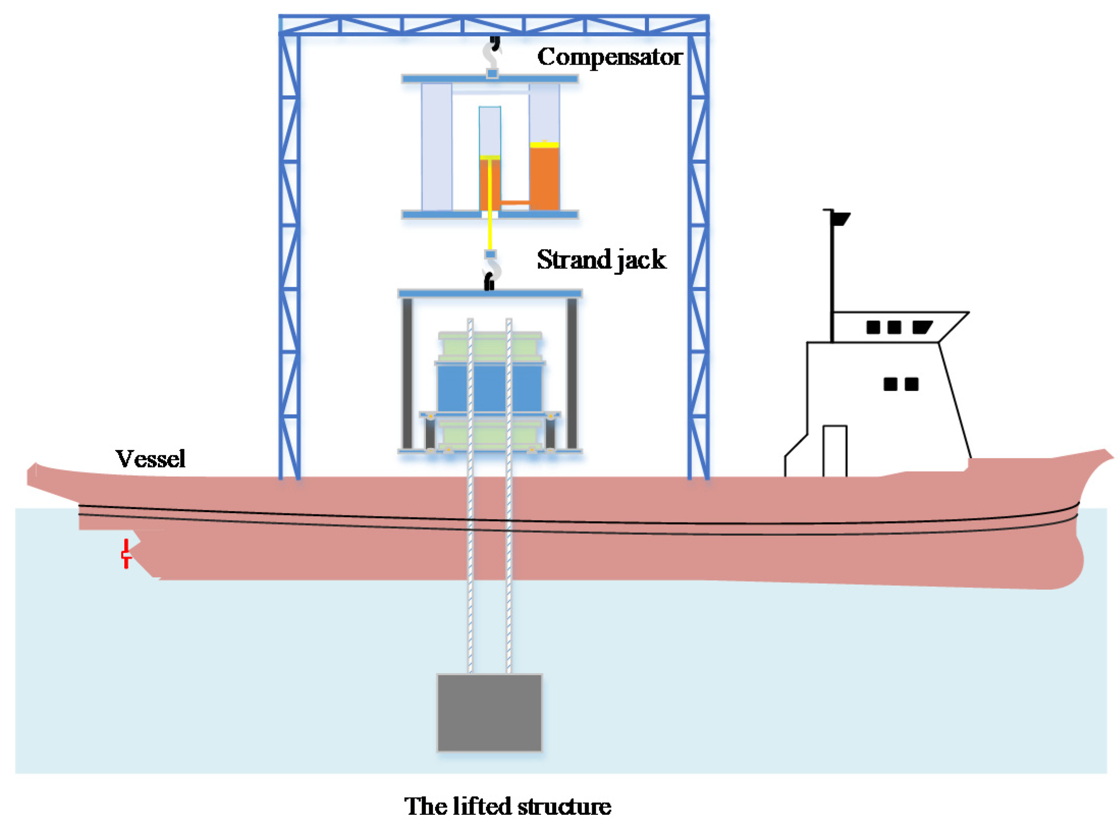
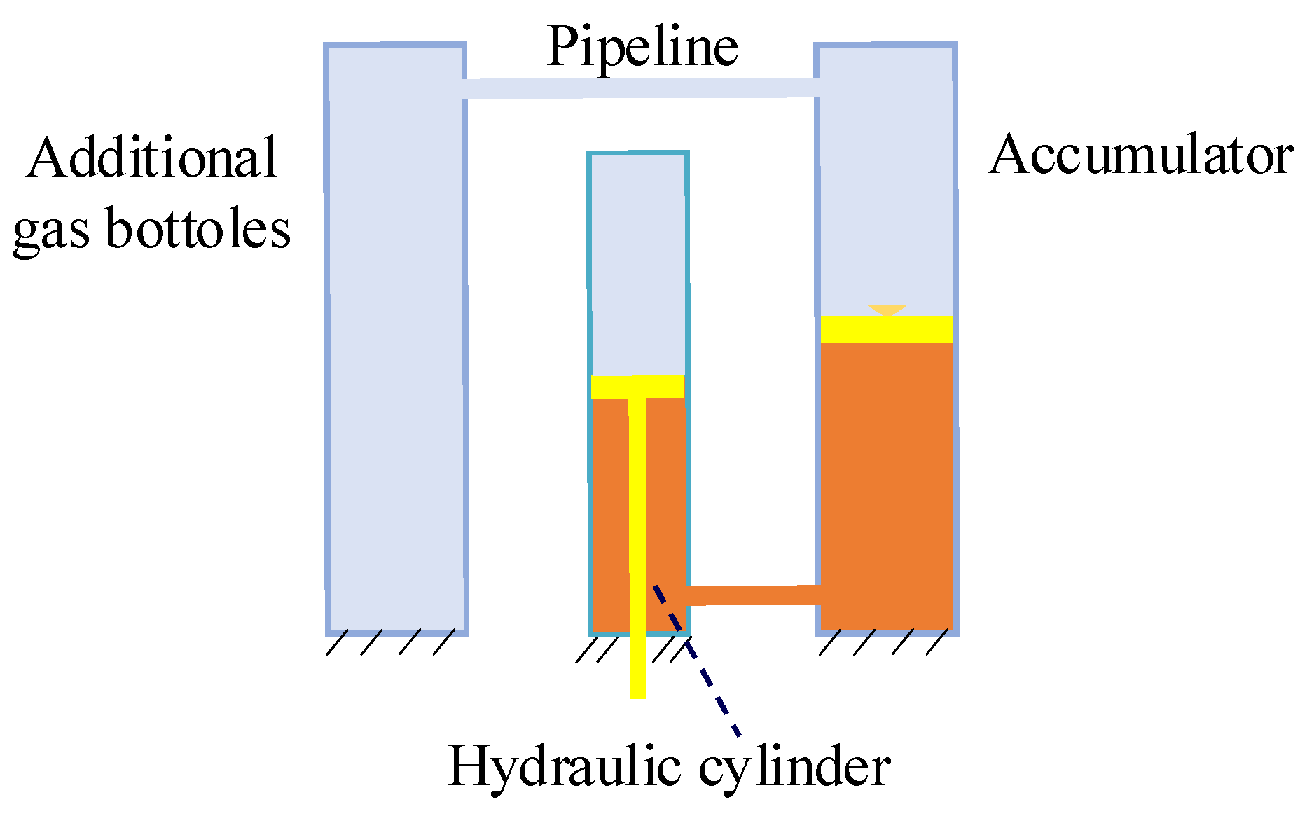
2.1. Configuration of the Lifting System and Working Principle of the Compensator

The schematic layout of the strand jack lifting system can be seen in Figure 2. It consists of five sub-systems: the vessel, the passive compensator, the strand jack, the strands, and the lifted structure. The passive compensator hangs below a hook. The rod of the hydraulic cylinder of the compensator is connected via a hook to the strand jack. Several strands suspend the lifted structure, which is submerged in water.
As shown in Figure 3, the passive compensator can be broken down into three parts: a hydraulic cylinder, a piston accumulator, and additional gas bottles. The lower chamber of the hydraulic cylinder is interconnected to the oil chamber of the piston accumulator by a pipeline. The gas chamber of the piston accumulator is interconnected to the additional gas bottles, which are filled with the pressured nitrogen. The compressibility of the gas provides the desired elasticity for the compensator. In order to improve compensation performance, soften stiffness is required. The piston accumulator is used for this purpose since it has the advantage that larger sizes are available, and it is easy to be interconnected with the additional gas bottles [15].
In static conditions, the gas volume needs to be adjusted accordingly thus as to set the piston of the hydraulic cylinder at the mid-stroke. As the vessel heaves upward, the force acting on the rode of the cylinder becomes larger due to the inertia of the lifted structure. As a result, the rod is stretched, and thus the gas is compressed, and the gas pressure increases. As the vessel heaves downward, the force acting on the rod becomes smaller. Then, the rod is contracted. In the above two situations, the piston rod of the hydraulic cylinder moves in the opposite direction of the vessel motion, thus as to compensate for the vessel motion.

2.2. Dynamic Model of the Strand Jack Lifting System

In order to accurately predict the lifting system dynamic behaviors of the lifting system, a coupling model of the strand jack together with the passive compensator and the strand-suspended structure is developed.
In modeling, two following issues are considered. The first one is that the suspended structure is lifted or lowered by the strands during the strand jack operation. In the case of deep-sea operations, the stiffness and mass of the strands have significant impact on the dynamic behaviors of the lifting system during its response to the heave excitation, since the length of the strands is more than 300 m. Therefore, the effect of the elasticity and the mass of the strands should be taken into account in the coupling model. The second issue is that since the lifted structure is submerged in water, the hydrodynamic force has to be considered due to its large size.
The assumptions below are made in the lifting system coupling model.
  • The hydraulic oil is uncompressible.
  • Neglecting leakage flows and seal friction forces of the hydraulic cylinder of the compensator.
  • All the strands have the same dimensions and mechanical properties.
  • Neglecting damping effect in the strands.
Figure 4 shows the schematic diagram of the strand jack lifting system. mj is the mass of the strand jack. As previously mentioned, a damped spring model is used to simulate the dynamic behavior of the compensator with stiffness kh and damping ch. The strand is modeled as lumped mass with elasticity. Moreover, the spring with stiffness ks refers to the stiffness of the strands. ms represents the mass of the strands, which is a function of the strand length, density, and number of strands. When the lifted structure moves in water, the reaction forces acting on it is modeled as the added mass ma and the hydrodynamic damping cp, which is governed by the flow condition and the shape of the lifted structure. In this paper, the lifted structure is approximated as a cuboid for simplicity. According to DNV-RP-H103 [16], ma can be given as 0.15ml, where ml is the mass of the lifted structure. Thus, the total mass mp lifted by the strand jack is given by mp = ms + ml + ma.
The vessel heave motion induced by the wave is assumed to be known and is modeled as a prescribed displacement function yb, which is applied to the base of the compensator. yj and yp are the absolute displacements of the base of strand jack and the lifted structure due to vessel motion, respectively. All displacement variables are defined in the earth-fixed coordinate frame.
According to Newton’s second law, the coupling model of the strand jack lifting system is given as:
m j y .. j + k h ( y j y b ) + c h ( y . j y . b ) + k s ( y j y p ) = 0 m p y .. p + k s ( y p y j ) + c p y . p = 0

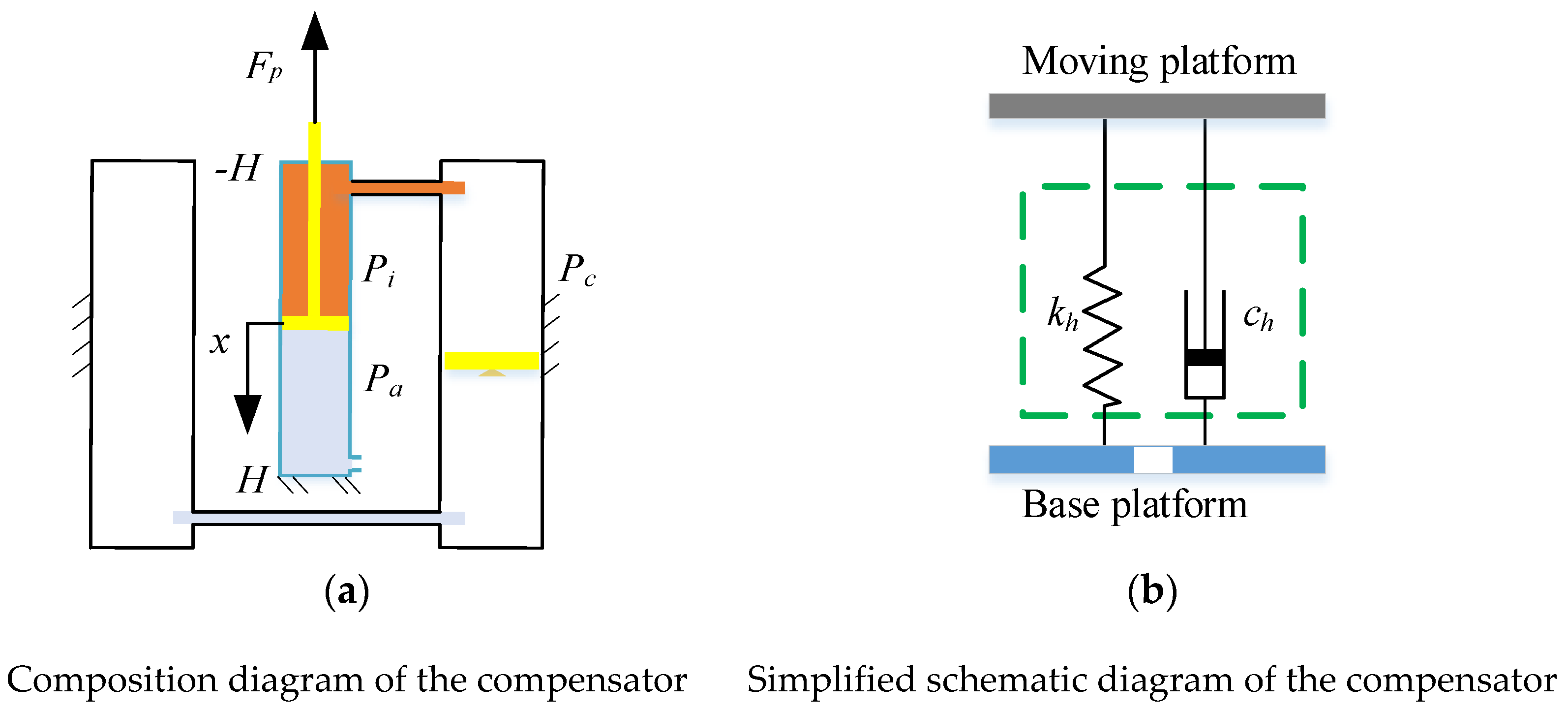
2.3. Mathematical Modeling of the Compensator

In this section, a nonlinear mathematical model of the compensator was developed, and a comparative analysis was carried out to analyze the influence of key design parameters on the dynamic response of the compensator.
The compensator was modeled by a nonlinear damped spring system. Figure 5 shows a simplification of the compensator in order to study its stiffness and damping coefficients in a more straightforward way. Assuming that the hydraulic cylinder has a stroke of 2H, piston diameter of Dp and piston rod diameter of Dr. The x-axis is along the axis of the cylinder with vertical upward displacement defined as positive, and the zero point of x-axis is at the cylinder mid-stroke. Obviously, the value range of x is [−H, H].
The cylinder was divided into two chambers by the piston, the gas chamber, and the oil chamber. The gas chamber was open to the atmosphere. Thus, the pressure Pa in the gas chamber was always the constant atmospheric pressure. In the static equilibrium condition, the piston was at the middle of its stroke. Pi0 and Vc0 are the initial pressure and initial volume of the gas corresponding to the static equilibrium position, respectively.

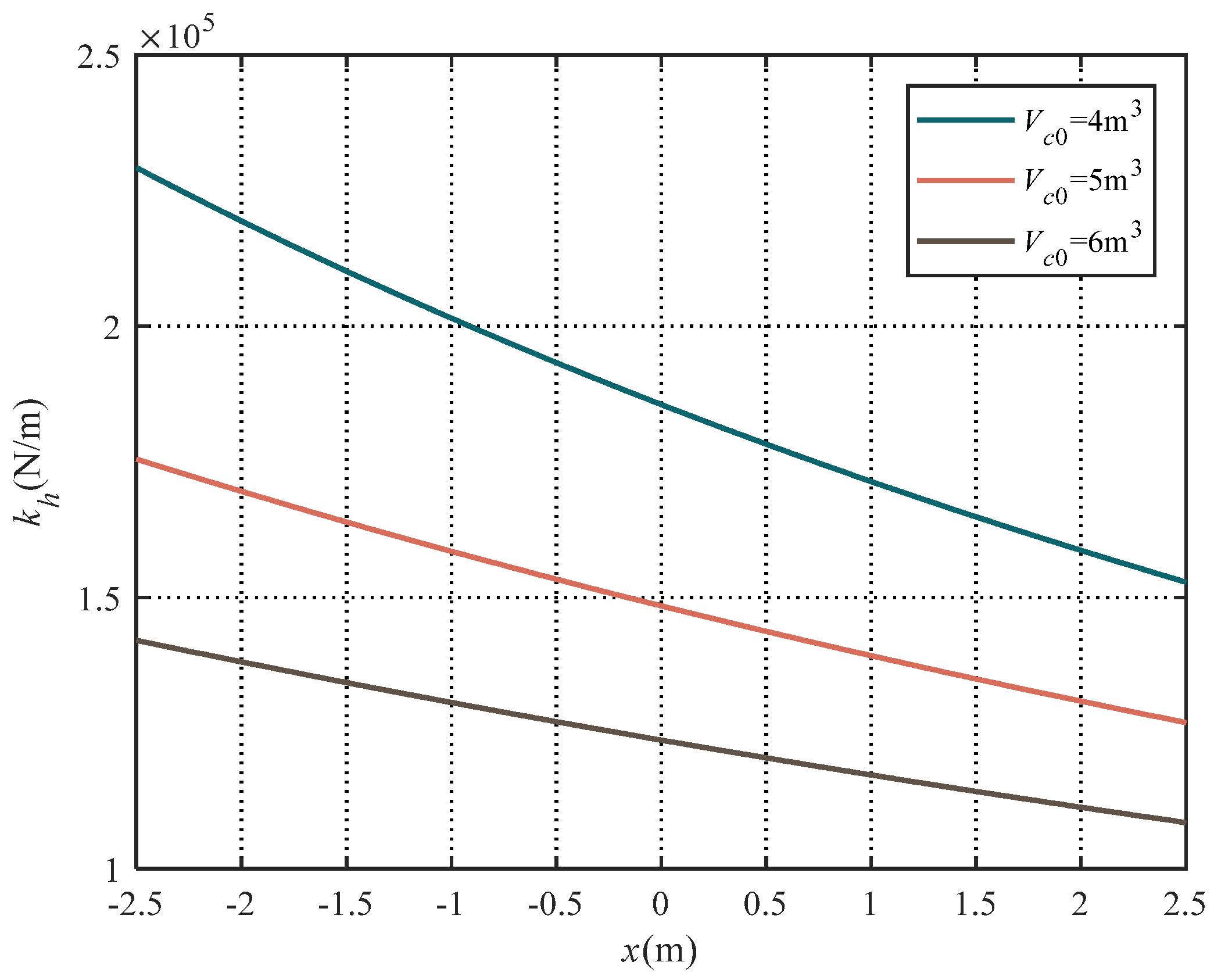
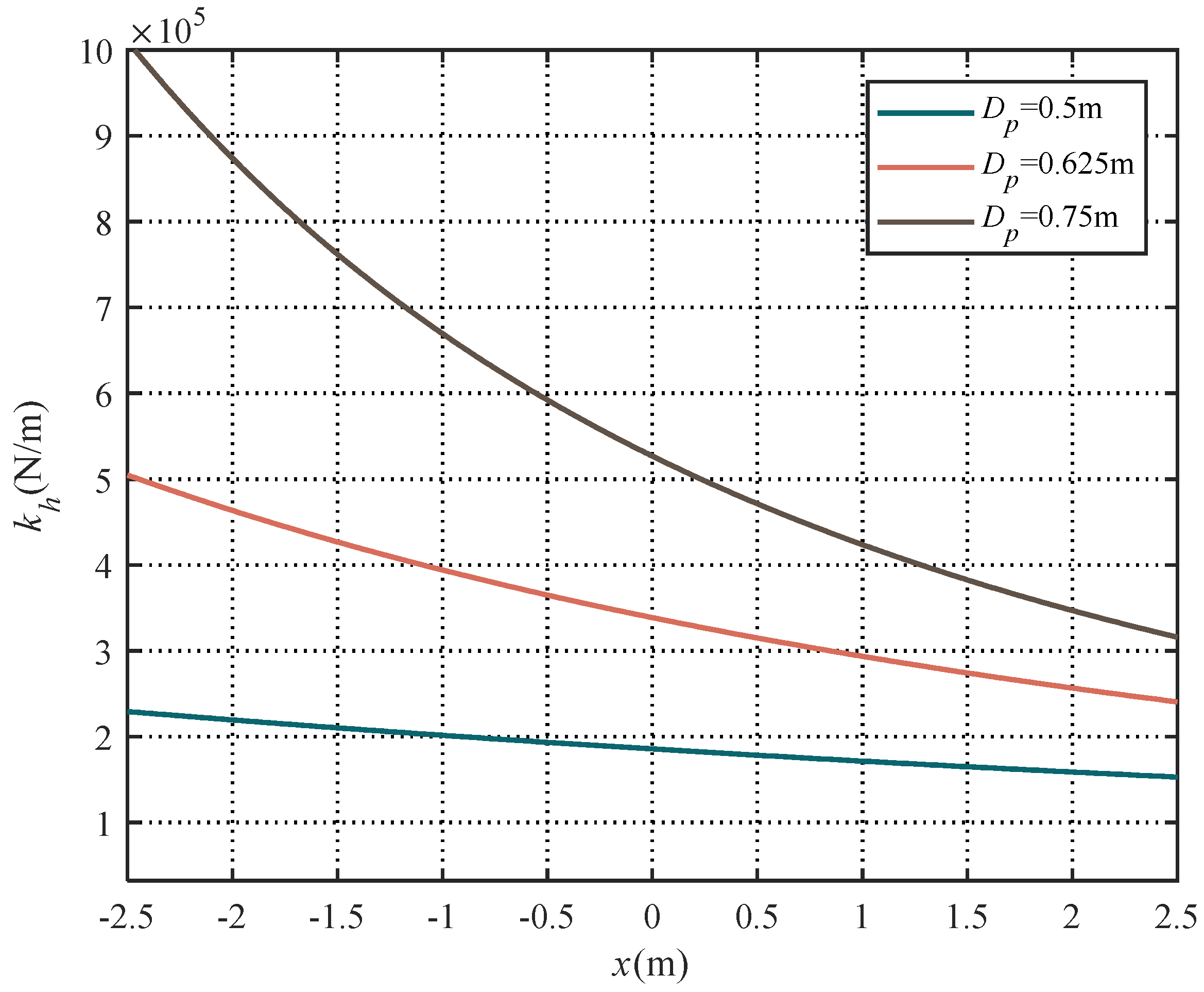
2.3.1. Stiffness of the Compensator

When the piston is at the static equilibrium position, unequal pressures on two sides of the piston create a force that balances the inertial force of the lifted structure. Let Fp be the force acting on the rod, and Fp = (mj + mp)g.
Under equilibrium condition, Pi0 is given as below:
P i 0 = F p + P a A d A d
where A d = π 4 ( D p 2 D r 2 ) , A d = π 4 D p 2 .
Under dynamic conditions, the piston of the hydraulic cylinder performs a relative axial motion induced by wave, and the resulting gas volume increased or decreased. Therefore, the gas pressure was a function of the piston position.
The vessel motion was in a short period of 8–10 s. Thus, there was insufficient time for the heat exchange between the gas of the compensator and the atmosphere. Therefore, the thermodynamics of the compression and expansion of the gas can be modeled as an adiabatic process [8]. Defining the displacement of the piston relative to the static equilibrium position as x. The following equation is valid:
P i ( x ) V c n ( x ) = P i 0 V c 0 n
where, n is adiabatic coefficient (n = 1.4 for nitrogen); Pi(x) and Vc(x) are the instantaneous pressure and the instantaneous volume of the gas, respectively, when the piston position is at x.
Thus, Pi(x) is given by:
P i ( x ) = P i 0 ( V c 0 V c ( x ) ) n
The gas volume equals to Vc(x) = Vc0 + x Ad. Substituting Vc(x) = Vc0 + x Ad into Equation (4) yields:
P i ( x ) = P i 0 ( V c 0 V c 0 + x A d ) n
The total force Fi provided by the compensator due to pressure differential across the piston can be written as follows:
F i = ( P i ( x ) P a ) A d
Substituting Pi(x) into Equation (6) gives Fi as
F i = A d P i 0 ( V c 0 V c 0 + x A d ) n A d P a
The stiffness can be derived by calculating the partial derivative of Fi with respect to the piston position x, as shown in Equation (8).
k h = F i x
Which can be expressed as:
k h = n P i 0 A d A d V c 0 n ( V c 0 + x A d ) n + 1
From Equation (9), it is seen that kh is a nonlinear function of Pi0, Vc0 and Ad for a given piston position x. In addition, the value of Ad is dependent on Dp and Dr. Therefore, the compensator stiffness kh can be optimized by choosing the value of the initial gas pressure, the initial gas volume, the rod diameter, and the piston diameter reasonably.
The compensator stiffness for different values of Vc0 is shown in Figure 6 when the piston was 500 mm in diameter, and the rod was 280 mm in diameter. Figure 6 indicates that the compensator stiffness decreased with increasing Vc0 for a given value of x. Moreover, the larger the gas volume was, the smaller the stiffness changes with the piston displacement. This was due to the fact that the changes in gas volume resulting from piston motion were equal. Moreover, when the gas volume was larger, the resulting pressure change was smaller due to the relatively smaller change rate of gas volume, thus the stiffness change was smaller.
As observed in Figure 6, the compensator stiffness increases with decreasing x for a constant Vc0. In addition, it is highly nonlinear with respect to x. In the case of Vc0 = 5 m3, the stiffness values were 1.76 × 10⁵, 1.49 × 10⁵ and 1.27 × 10⁵, respectively, when x = −2.5, 0 and 2.5. The maximum stiffness change rate was 38.6% compared to minimum stiffness when the piston moves from the top dead to the bottom dead. Clearly, the compensator stiffness changed significantly during the motion of the cylinder piston. Therefore, the assumption was invalid for the studied problem in this paper that the compensator stiffness was constant due to small gas volume change. As a result, it was more accurate to use nonlinear stiffness to predict the compensator’s dynamic response.
As previously mentioned, Ad is another key parameter affecting the stiffness in view of the compensator design. Equation (9) suggests that as Ad decreases, the stiffness was reduced. As a result, we can obtain different stiffness by changing the values of Dp and Dr, since Ad is a function of Dp and Dr.
Figure 7 shows the compensator stiffness for different values of Dp when the piston moves from bottom dead to top dead. As Dp increases, the compensator stiffness increased rapidly. When the piston was at the mid-stroke, namely x = 0, an increase of Dp by 15% will increase the value of kh by nearly 100% at maximum. Therefore, the piston diameter had more influence on the compensator stiffness than gas volume.
From Figure 6 and Figure 7, it can be observed that the compensator stiffness depends on the values of Dp and Vc0. Thus, they must be carefully chosen, or else the compensator may not work.

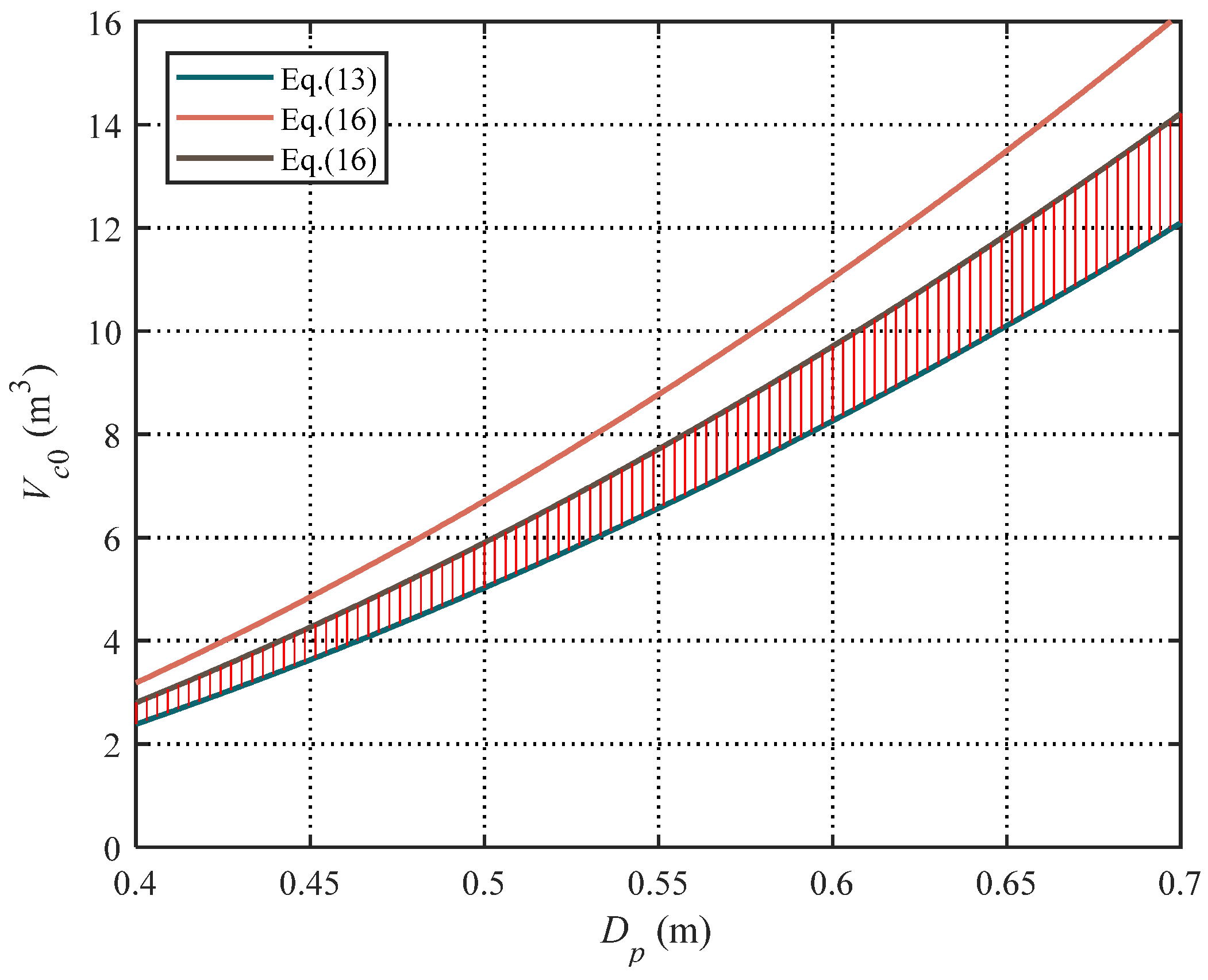
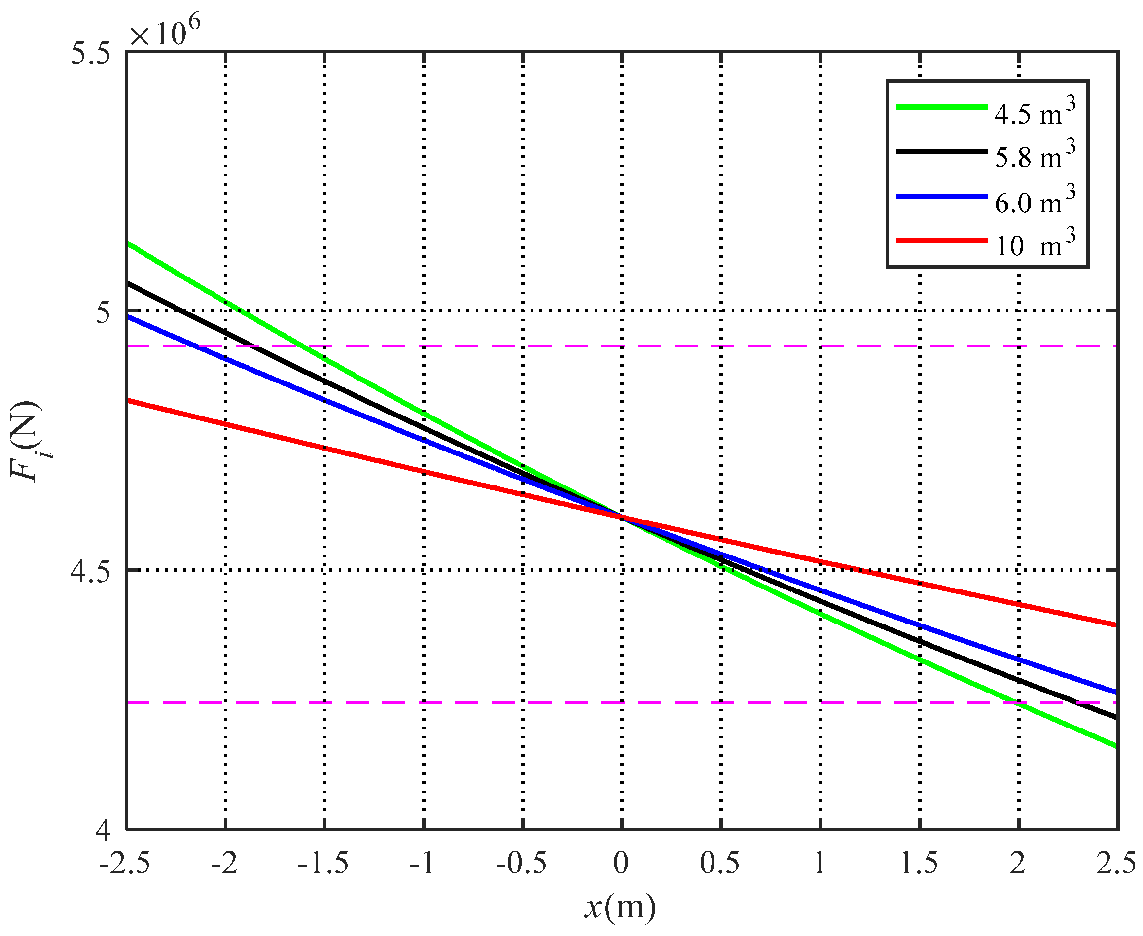
2.3.2. Optimization of the Gas Volume

The proposed compensator was modeled as a parallel spring-damper system in this paper. According to vibration theory, vibration isolation does not occur until the frequency ratio satisfies the following inequality.
ω ω n μ
where ω is the frequency of the vessel motion, ω is the natural frequency of the compensator, and μ = 2 .
The natural frequency of the compensator can be calculated as follows:
ω n = k h m v
where mv = mj + mp.
From Equations (10) and (11), the compensator stiffness must satisfy Equation (12) thus as to mitigate the transmission of heave movement from the vessel to the lifted structure.
k h 4 π 2 m v μ 2 T 2
where T is the period of the wave-induced vessel motion.
Replacing kh with its expression in Equation (3), yields:
V c 0 1 2 α + 1 4 α 2 β α
where α = 4 π 2 m v n A d μ 2 T 2 ( m v g + P 2 A d ) , β = ( n + 1 ) x A d .
Equation (9) illustrates that the compensator stiffness is a function of the piston position x. The value of the compensator stiffness is maximum when x = −H. Therefore, if the compensator stiffness of x = −H satisfies Equation (13), the compensator stiffness of other positions will satisfy Equation (13). Setting x = −H in Equation (13), yields:
V c 0 1 2 α + 1 4 α 2 β H α
where β H = - ( n + 1 ) H A d .
Equation (14) gives lower bound of the Vc0.
The compensator acts as a hydro-pneumatic spring. When the piston oscillates around its equilibrium position, the spring force exerted by the compensator changes dynamically. The range of the spring force variation was very important, since the spring force must balance the external load of the compensator. However, the cylinder stroke was limited. This means that the spring forces in the top dead and the bottom dead must be enough to balance the external load. Otherwise, the piston will hit the top end cover or the bottom end cover. It is very dangerous since the compensator is impulsively loaded when the piston hits the end cover. The resulting rapid increase in the strand tension is very dangerous to safety.
In the normal operation of the compensator, the extreme load applied to the compensator is assumed to be Fp ± ξFp, where ξ is specified as a fraction of Fp. Therefore, the force exerted by the gas is required to be in the range of [FpξFp,Fp + ξFp] in order to avoid hitting the end cover of the cylinder. Let [vd,vu] be the feasible value range of the initial gas volume vc0. if vc0 > vu, the increasing force induced by the compression of the gas from x = 0 to x = −H is less than ξFp. As a result, the piston will hit the bottom end cover of the cylinder. Similarly, if vc0 < vd, the decreasing force induced by the expansion of the gas from x = 0 to x = H is more than ξFp. As a result, the piston will hit the top end cover of the cylinder.
Based on the above discussion, the following inequality must hold to avoid hitting the end cover of the cylinder.
P i ( H ) A d m v g ( 1 + ξ ) + P a A d P i ( H ) A d m v g ( 1 ξ ) + P a A d
Solving Equation (15), yields:
V c 0 φ H A d φ 1 V c 0 φ H A d 1 ϕ
where, φ = ( m v g ( 1 + ξ ) + P a A d P i 0 A d ) 1 n , ϕ = ( m v g ( 1 - ξ ) + P a A d P i 0 A d ) 1 n .
In the view of the compensator design, the initial gas volume must be carefully chosen to satisfy Equations (13) and (16) thus that the desired stiffness is obtained, as well as avoiding hitting the end cover. Figure 8 shows the feasible region for Vc0 and Dp. Values in the red region are feasible choices for the initial gas volume and the piston diameter, which satisfies Equations (7) and (10).
Figure 8 clearly indicates that if the smaller Dp is chosen, the desired stiffness will be achieved using less gas volume. Otherwise, more gas volume is needed to obtain the identical stiffness for the case of the larger Dp. The size of the compensator will become smaller by decreasing the piston diameter Dp. However, decreasing the piston diameter Dp results in increasing the pressure in the compensator, which raises the requirement to the strength of the cylinder. Therefore, there is a tradeoff process between the gas volume and the piston diameter for an appropriate value of the stiffness.
Figure 9 shows numerical simulation results of spring force versus piston displacement curves for four different values of Vc0. The following parameters are used in the numerical simulations: Dp = 0.5 m, Dr = 0.28 m and H = 2.5 m; ml = 400 t; ma = 0.15 ml; mj = 1 t; ms = 7.14 t; ξ = 0.075. The two horizontal pink dashed lines represent the upper bound and the lower bound of the external force applied on the cylinder piston rod, respectively. The four curves intersect at (0, 4.60 × 10⁶), which is the static spring force exerted by the compensator. Since the initial gas volumes are different, there are significant differences in the range of the spring forces. Table 1 lists the spring forces when the piston is at x = 2.5 and x = −2.5. In the case of Vc0 = 10 m3, the compensator stiffness is too softer. As a result, the piston will hit the end cover of the cylinder, for which Equations (13) and (15) do not hold. In the case of Vc0 = 6 m3, the piston will hit the top end cover of the cylinder since the spring force Fi at x = 2.5 was less than the force required. In the case of Vc0 = 4.5 m3, although the piston will not hit the end cover of the cylinder, the compensation efficiency was limited since the initial gas volume does not satisfy Equation (13). Vc0 = 5.8 is the only case that satisfies Equations (13) and (15). The piston will not hit the end cover of the cylinder. Meanwhile, the maximum and minimum spring force is Fp = [4.25 × 10⁶, 4.94 × 10⁶].

2.4. Dynamic Model of the Strand Jack with the Passive Compensator

2.4.1. Damping Model of the Compensator

Damping forces of the compensator originate from two main sources: mechanical friction, such as friction due to relative motion between the piston and the cylinder; fluid resistance in the pipeline between the cylinder and the accumulator. Since the friction force between the piston and the cylinder was relatively small compared with the external load of the compensator, it was not taken into account in this paper. We will only consider the resistive effect along the pipeline.
Following the Hagen–Poiseuille equation, the pressure drop along the pipeline can be calculated by:
P i P c = 32 μ L t u D t 2
where, Pi and Pc represents the instantaneous pressure of oil pressure in the hydraulic cylinder and the accumulator, respectively; Lt is the length of the pipeline; μ is the dynamic viscosity of hydraulic oil; u is the average flow rate of hydraulic oil through the pipeline; Dt is the diameter of the pipeline.
Thus, the damping force Fc in the pipeline is:
F c = A d ( P i P c ) = 32 μ L t u D t 2 A d
The average flow rate of hydraulic oil through pipeline is given by:
u = 4 A d ( y . b y . j ) π D t 2
Substituting Equation (19) into Equation (18), the damping force Fc can be expressed as:
F c = 128 μ L t π D t 4 A d 2 ( y . b y . j )
Differentiating Fc with respect to y . b y . j , the damping coefficient ch can be expressed as:
c h = d F c d ( y . b y . j ) = 128 μ L t π D t 4 A d 2

2.4.2. Strand Model

A simple model of strands was used in this paper, which only considers the strand’s equivalent stiffness neglecting the damping force and the hydrodynamic drag force of strands. This model is valid as the velocity of the lifted structure is small.
The tension in one strand can be calculated as follows:
T = A s σ = A s E δ L s
where E is the Young’s modulus of strand, As is the intersectional area of strand, Ls is the strand length, and δ is the strand extension.
Then, the stiffness of one strand following from Hook’s law can be written as follows:
k s 1 = T δ = A s E L s
There are q strands used in the strand jack, and the geometric and mechanical parameters of all strands are assumed to be identical. Thus, they can be modeled as q springs in parallel with common stiffness. The resulting stiffness can be expressed as:
k s = q A s E L s
It can be seen from Equation (24) that the strand properties, length, and quantity dominate the stiffness of the strands.

2.4.3. Hydrodynamic Damping Coefficient

Excited by vessel motion, the lifted structure vibrates in water, which is a viscous fluid. Thus, the lifted structure experiences reacting force, viscous damping force due to the surrounding fluid. A convenient approximation that can be used to estimate the viscous damping force for the submerged lifted structure can be derived based on Morison’s equation. It can be expressed as:
F d = 1 2 ρ | v l | v l C d A l
where ρ is the density of seawater, vl is the velocity of the lifted structure in water, Al is the lifted structure’s nominal cross-sectional area in the vertical direction, Cd is the drag coefficient.
The hydrodynamic damping coefficient cp is given by:
c p = F d v l = 1 2 ρ | v l | C d A l = 1 2 ρ | y . p | C d A l

3. Numerical Simulation

To evaluate the compensator’s effectiveness and the influence of key parameters on the efficiency of the compensator, the numerical simulations were carried out.

3.1. Numerical Setting

In the simulations, the vessel motion was given by Equation (27).
y b = A sin 2 π T t
where, A = 2.1 m and T = 6 s denote the amplitude and frequency, respectively.
The shape of the lifted structure was simplified as a cuboid with the dimensions of 5 × 1.2 × 0.5 m3. The damping coefficient Cd equaled 0.95 according to DNV-RP-H103 [16]. The parameters of the strand and simulation used in the simulations are listed in Table 2 and Table 3.

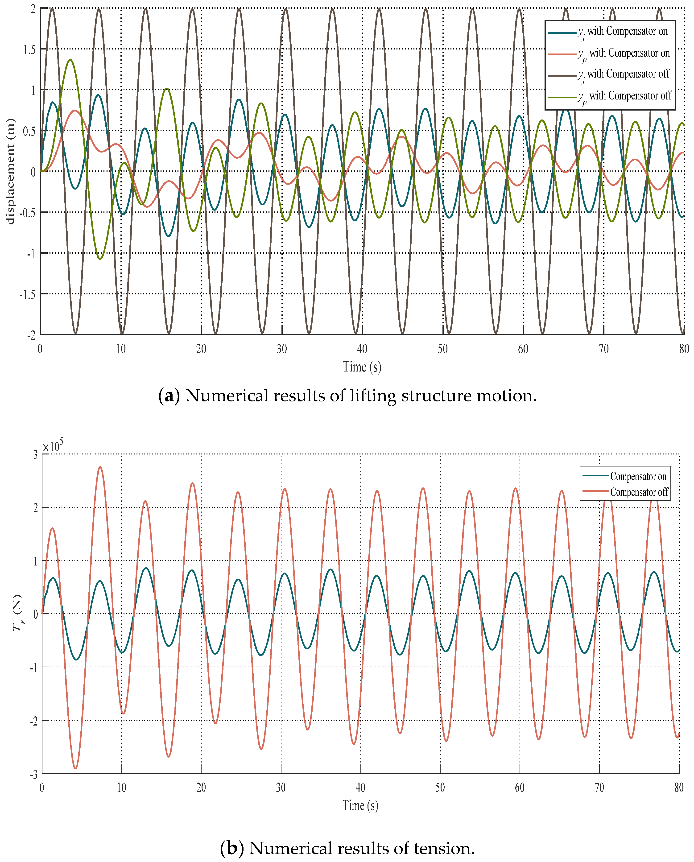
3.2. Numerical Results

To illustrate the effectiveness of the proposed compensator, numerical simulations were performed for 2 cases, the compensator on and the compensator off. Specifications of the compensator used in the simulations are summarized in Table 4.
Figure 10 depicts the simulation results of the lifted structure motion and the dynamic tension in the strand. It is seen from Figure 10 that there was a significant reduction in the displacement yj and yp and dynamic tension Tr when the compensator was used. This illustrates the effectiveness of the compensator. Moreover, it was noted that the displacement amplitude of yp was smaller than the displacement amplitude of yj in both cases. This indicates that the displacement of the lifted structure decreased due to the strand elasticity.
The compensator had a nonlinear damping feature due to the flow characteristic of the pipeline. The influences of damping characteristics on the compensator efficiency and dynamic tension were studied for the various diameters of the pipeline, as shown in Figure 10. In Figure 11, responses were plotted for 3 different diameters dt of pipeline. As the pipeline diameter increased, the corresponding amplitude values of yp and Tr decreased. This indicated that the smaller damping values were better since the damping value decreased and the compensation efficiency increased with increasing the diameter of the pipeline. The reason for increased compensation efficiency was that the smaller damping force produced a smaller time delay to the compensator.

4. Conclusions

This paper presented a nonlinear dynamic model of the passive compensator, incorporating nonlinearity of the compensator stiffness. The comparative analysis is carried out to analyze the influence of key design parameters on the dynamic response of the compensator. The results indicate that it is more accurate to use nonlinear stiffness to predict the compensator’s dynamic response. Moreover, it is established that the piston diameter has more influence on the compensator stiffness than the gas volume via numerical simulations. The heave compensation performance of the strand jack lifting system employing a passive compensator is evaluated and compared to different conditions. It is concluded that the lifted structure displacement and the strand dynamic tension can be improved considerably using the passive compensator.

Author Contributions

Conceptualization, Y.Z., J.X., B.Y. and S.W.; methodology, Y.Z., J.X., B.Y. and S.W.; software, B.Y. and S.W.; validation, J.X., B.Y.; formal analysis, Y.Z., B.Y. and S.W.; investigation, Y.Z.; resources, Y.Z. and J.X.; data curation, S.W.; writing—original draft preparation, Y.Z.; writing—review and editing, Y.Z. and B.Y.; visualization, Y.Z. and S.W.; supervision, Y.Z. and J.X.; project administration, Y.Z.; funding acquisition, Y.Z. and J.X. All authors have read and agreed to the published version of the manuscript.

Funding

The authors gratefully acknowledge the financial support from The Natural Science Foundation of Heilongjiang Province, China (no. E2018022), Information Technology of the People’s Republic of China-Floating Security Platform Project (the second stage), and the Opening Fund of Acoustics Science and Technology Laboratory (grant no. SSKF2020009).

Institutional Review Board Statement

Not applicable.

Informed Consent Statement

Not applicable.

Data Availability Statement

The data that support the findings of this study are available from the corresponding author upon reasonable request.

Acknowledgments

The authors would like to thank the members of the Marine Electromechanical Systems Research Institute for their continued support and discussion.

Conflicts of Interest

The authors declare that the research was conducted in the absence of any commercial or financial relationships that could be construed as a potential conflict of interest.

References

  1. Wang, A.M.; Jin, X.; Liu, Y.; Tao, F.; He, C.; He, M. A Low-Deck Floatover Installation Technology with Strand Jack Lifting Scheme. In Proceedings of the 28th International Ocean and Polar Engineering Conference, Sapporo, Japan, 10–15 June 2018. [Google Scholar]
  2. Wang, W.; Yang, M.; Bian, Y.; Yan, S.; Yang, J.; Qin, L. Study of hydraulic synchronous lifting system for shipwreck salvage with cushion compensation. Chin. J. Constr. Mach. 2017, 15, 400–405. [Google Scholar]
  3. Mi, Z.; Pan, L.; Chen, J.; Chen, L.; Wu, R. Consecutive lifting and lowering electrohydraulic system for large size and heavy structure. Autom. Constr. 2013, 30, 1–8. [Google Scholar] [CrossRef]
  4. Woodacre, J.K.; Bauer, R.J.; Irani, R.A. A review of vertical motion heave compensation systems. Ocean Eng. 2015, 104, 140–154. [Google Scholar] [CrossRef]
  5. Quan, W.; Liu, Y.; Zhang, Z.; Li, X.; Liu, C. Scale model test of a semi-active heave compensation system for deep-sea tethered ROVs. Ocean Eng. 2016, 126, 353–363. [Google Scholar] [CrossRef]
  6. Nam, B.W.; Kim, N.W.; Hong, S.Y. Experimental and numerical study on coupled motion responses of a floating crane vessel and a lifted subsea manifold in deep water. Int. J. Nav. Archit. Ocean Eng. 2017, 9, 552–567. [Google Scholar] [CrossRef]
  7. Collins, M.D. Applications of a Motion Compensation Stabilized Vertical Array of Hydrophones. IEEE Access 2019, 7, 79433–79437. [Google Scholar] [CrossRef]
  8. Lee, H.-W.; Roh, M.-I.; Ham, S.-H.; Ha, S. Dynamic simulation of the wireline riser tensioner system for a mobile offshore drilling unit based on multibody system dynamics. Ocean Eng. 2015, 106, 485–495. [Google Scholar] [CrossRef]
  9. Kang, H.-S.; Kim, M.-H.; Aramanadka, S.S.B. Tension variations of hydro-pneumatic riser tensioner and implications for dry-tree interface in semisubmersible. Ocean Syst. Eng. 2017, 23, 21–38. [Google Scholar] [CrossRef]
  10. Chen, B.; Yu, J.; Yu, Y.; Xu, L.; Hao, S.; Wu, C.; Wu, H. Study on key performance parameters of hydro-pneumatic tensioner for top tensioned riser. Appl. Ocean Res. 2019, 84, 206–215. [Google Scholar] [CrossRef] [Green Version]
  11. Duc, L.V.; Trong, N.K. Combination of input shaping and radial spring-damper to reduce tridirectional vibration of crane payload. Mech. Syst. Signal Process. 2019, 116, 310–321. [Google Scholar]
  12. Quan, W.; Liu, Y.; Zhang, A.; Li, X. The nonlinear finite element modeling and performance analysis of the passive heave compensation system for the deep-sea tethered ROVs. Ocean Eng. 2016, 127, 246–257. [Google Scholar] [CrossRef]
  13. InterMoore Inc. Depth Compensated Subsea Passive Heave Compensator. U.S. Patent US7934561B2, 3 May 2011.
  14. Cannell, D.; Labbe, C.; Odigie, E.; Riddell, S. Passive Heave Compensator. U.S. Patent US9718652B2, 1 August 2017. [Google Scholar]
  15. Peter, A. Motion Control in Offshore and Dredging Industry; Springer: Dordrecht, The Netherlands, 2010. [Google Scholar]
  16. Veritas, D.N. Dnv-rp-h103 Modelling and Analysis of Marine Operations; Det Norske Veritas: Bærum, Norway, 2011. [Google Scholar]
Figure 1. Structure of strand jack.
Jmse 09 00714 g001
Figure 2. Schematic layout of the strand jack lifting system.
Jmse 09 00714 g002
Figure 3. Schematic layout of the compensator.
Jmse 09 00714 g003
Figure 4. Schematic diagram of the strand jack lifting system.
Jmse 09 00714 g004
Figure 5. Schematic diagram of the compensator.
Jmse 09 00714 g005
Figure 6. Effect of Gas Volume on Stiffness.
Jmse 09 00714 g006
Figure 7. Effect of piston diameter on stiffness (Vc0 = 4 m3, Dr = 0.28 m).
Jmse 09 00714 g007
Figure 8. Feasible region for Vc0 and Dp.
Jmse 09 00714 g008
Figure 9. Force-displacement relationship for various values of the initial gas volume.
Jmse 09 00714 g009
Figure 10. Numerical results.
Jmse 09 00714 g010
Figure 11. Responses of the compensator with different dt.
Jmse 09 00714 g011
Table 1. External loads and Spring forces at x = 2.5 and x = −2.5.
Vc0 = 4.5Vc0 = 5.8Vc0 = 6Vc0 = 10
Spring force at x = −2.5 (N)5.14 × 1065.06 × 1064.99 × 1064.83 × 106
Spring force at x = 2.5 (N)4.15 × 1064.21 × 1064.27 × 1064.39 × 106
Table 2. Specifications of the strand.
Diameter (mm)Cross-Section Area (mm2)Young’s Modulus (GPa)Mass per Unit Length (kg/m)
15.21391951.19
Table 3. Simulation parameters.
List of ItemsValue
Mj, ton1
Ml, ton400
L, m300
ρ, g/cm31.02
Table 4. Specifications of the compensator.
List of ItemsValue
Vd0, m35.8
dp, mm500
dr, mm280
dt, mm50
lt, m2
Publisher’s Note: MDPI stays neutral with regard to jurisdictional claims in published maps and institutional affiliations.

