Article

Diffraction and Radiation of Water Waves by a Heaving Absorber in Front of a Bottom-Mounted, V-shaped Breakwater of Infinite Length

by
Dimitrios N. Konispoliatis
* and
Spyridon A. Mavrakos
Laboratory for Floating Structures and Mooring Systems, Division of Marine Structures, School of Naval Architecture and Marine Engineering, National Technical University of Athens, GR 157-73 Athens, Greece
*
Author to whom correspondence should be addressed.
J. Mar. Sci. Eng. 2021, 9(8), 833; https://doi.org/10.3390/jmse9080833
Submission received: 9 July 2021 / Revised: 27 July 2021 / Accepted: 29 July 2021 / Published: 31 July 2021
(This article belongs to the Section Ocean Engineering)

Abstract

:
In the present study, the problems of diffraction and radiation of water waves by a cylindrical heaving wave energy converter (WEC) placed in front of a reflecting V-shaped vertical breakwater are formulated. The idea conceived is based on the possible exploitation of amplified scattered and reflected wave potentials originating from the presence of V-shaped breakwater, towards increasing the WEC’s wave power absorption due to the wave reflections. An analytical solution based on the method of images is developed in the context of linear water wave theory, taking into account the hydrodynamic interaction phenomena between the converter and the vertical wall. Numerical results are presented and discussed concerning the hydrodynamic forces on the absorber and its wave power efficiency for various examined parameters, namely, the breakwaters’ forming angle, the distance between the converter and the vertical walls and the wave heading angle. The results show that the amount of the harvested wave power by the WEC in front of the walls is amplified compared to the wave power absorbed by the same WEC in the open sea.

1. Introduction

The rise in the electricity demand from coastal communities and the availability of wave energy sources have boosted the growth of the global wave energy market. The wave energy market is projected to reach USD 107 million by 2025 from an estimated market size of USD 44 million in 2020, at a compound annual growth rate (CAGR) of 19.3% during the forecast period [1]. The main challenge, however, for the offshore renewable industry is to reduce the construction, installation and maintenance costs for WECs, ensuring operational efficiency, fatigue resistance and structural integrity during severe environmental conditions. Therefore, the installation and operation of marine renewables near- and onshore is a preferred choice for wave energy absorption, reducing in parallel the levelized cost of energy. The combination of wave energy devices with existing maritime facilities such as a breakwater or a harbor is triggered by easier electricity transmission to the mainland allowing for common infrastructure (i.e., electrical cable; power transfer equipment, etc.) and a reduction in the wave action intensity on the shore [2].
Many design concepts of breakwater-WEC systems have been proposed in the last decades. In the earlier stages, the systems focused on caisson breakwaters, rubble mound- and vertical breakwaters [3,4]. These systems maintain their principal function of sheltering a location from the action of waves (i.e., coastal and harbor protection) but with important benefits to the wave power production due to the inclusion of the WEC. Indicative examples of a caisson breakwater-WEC system and a vertical-wall breakwater-WEC system include the Mutriku system in Spain [5] and the WEC system at the port of Heraklion in Crete [6]. Recently, floating breakwaters have been presented as an alternative solution to bottom-mounted breakwaters. Deep water areas or poor foundation conditions, as well as environmental requirements, such as shore erosion phenomena, water quality, layout relocation and aesthetic considerations, advocate for the application of such structures. Floating breakwaters are favored for their lower construction cost and the added advantages of being flexible and environmentally friendly [7,8]. Although many studies were performed to determine the performance of those floating barriers integrated with WECs of various designs, no floating breakwater-WEC system has been developed or set into commercialization yet.
As a common wave energy device, the heaving absorber has been proved to be the more favorable converter for breakwater-WEC systems, due to the modular and compact design of the device and its variable geometry. Looking towards the multi abilities provided by the installation of heaving devices in front of maritime structures, numerous designs of such systems (i.e., WEC-breakwater) have been reported in the literature. In [9,10], the performance characteristics of an array of five wave energy heaving converters, placed in a row, in front of a vertical, bottom-mounted, reflecting breakwater (i.e., vane-type vertical wall) have been theoretically and experimentally investigated, whereas in [11,12,13,14], the diffraction and radiation problems of a uniform and a truncated cylindrical body in front of a vertical wall have been formulated. Furthermore, in [15,16], the hydrodynamic characteristics and wave power absorption by arrays of several types of heaving devices placed in front of a linear breakwater have been evaluated. Recent relevant studies [17,18] have examined the wave interactions among multiple cylinders in front of a vertical wall and the hydrodynamics of a submerged horizontal cylinder in front of a vertical breakwater. In these works, a completely reflecting vertical boundary of infinite extent is assumed in conjunction with the use of the method of images. The method transforms the examined breakwater-WEC system into an imaginary physical problem; i.e., the problem of N number of bodies in front of a vertical wall is equivalent to that of an array of 2N bodies (the initial and their image devices) with respect to the breakwater, without the presence of the vertical wall. In [19], the limitations of the method of images along with the assumption of a “pure” wave reflecting wall on the calculation of a heaving device array in front of a vertical wall were examined. Furthermore, in [20], the effect of a finite length breakwater on the hydrodynamics of an array of cylindrical heaving WECs has been studied. Nevertheless, in this work, the breakwater is being considered as an elliptical cylinder with zero semi-minor axis. Recently, in [21], the absorption ability of an array of semi-immersed, oblate spheroidal heaving WECs placed in front of a vertical wall of finite length is examined.
With respect to breakwater-WEC systems with linear walls (vane type), orthogonal breakwaters (i.e., forming a right angle) have been recently examined too, demonstrating the amplified scattered and reflected waves originating from the presence of the orthogonal vertical walls, which lead to an increase in the wave power efficiency of the converter. In [22,23], the effect of a sea-bottom-fixed orthogonal breakwater on the hydrodynamics of a bottom seated cylindrical body was examined, whereas in [24], a theoretical analysis of a vertical cylindrical floater in front of an orthogonal breakwater was presented. The effect of an orthogonal wall on the power efficiency of a single WEC (i.e., a heaving absorber and an oscillating water column device OWC) placed in a random location in front of the two walls was examined in [25].
Concerning the V-shaped breakwaters, several different types of patents have been presented in the last decades [26,27]; in May 1999, the U.S. Army Engineer Research and Development Center launched a revolutionary concept in V-shaped breakwaters to reduce the impact of elevated sea states during humanitarian operations [28,29]. This type of barrier provides a sheltered region in the interior of the V during the wave propagation in the direction outside the breakwater. Since then, several studies have followed this, describing the diffracted waves due to the presence of the breakwater. Specifically, in [30,31] the diffraction problem of water waves incident upon a single V-shaped breakwater has been derived. Additionally, in [32], the dynamic pressure distribution and its amplitude on the wet surface of the breakwater was calculated and analyzed in regular waves, whereas, in [33], the wave pressure on the wet surface of a V-shaped floating breakwater in random seas was investigated. Regarding the breakwater-WEC system, to the best of author’s knowledge, no research has been presented for a WEC placed in front of a V-shaped breakwater.
In the present work, a heaving absorber wave energy converter has been placed in the interior area of a V-shaped, bottom-fixed, surface-piercing breakwater. The wave train is considered, propagating towards the formed interior area, to benefit from the wave reflections on the walls in order to amplify the wave power efficiency of the converter. Several distances between the converter and the vertical walls, wave heading angles and breakwater angles are examined to investigate the effect of the walls on the device’s performance (i.e., hydrodynamics and power absorption). The problems of diffraction and radiation of water waves by the converter placed in front of the breakwater are formulated by applying (a) the method of matched eigenfunction expansions, for the determination of the velocity potentials in the fluid domains surrounding the absorber; and (b) the method of images, for the simulation of the effect of the vertical walls on the breakwater-WEC system.
The study is structured as follows: Section 2 describes the formulation of the corresponding diffraction and radiation problems; in Section 3, the converter’s motion equations are solved. Section 4 is devoted to the presentation and the discussion of the results. Finally, in Section 5, the conclusions are drawn.

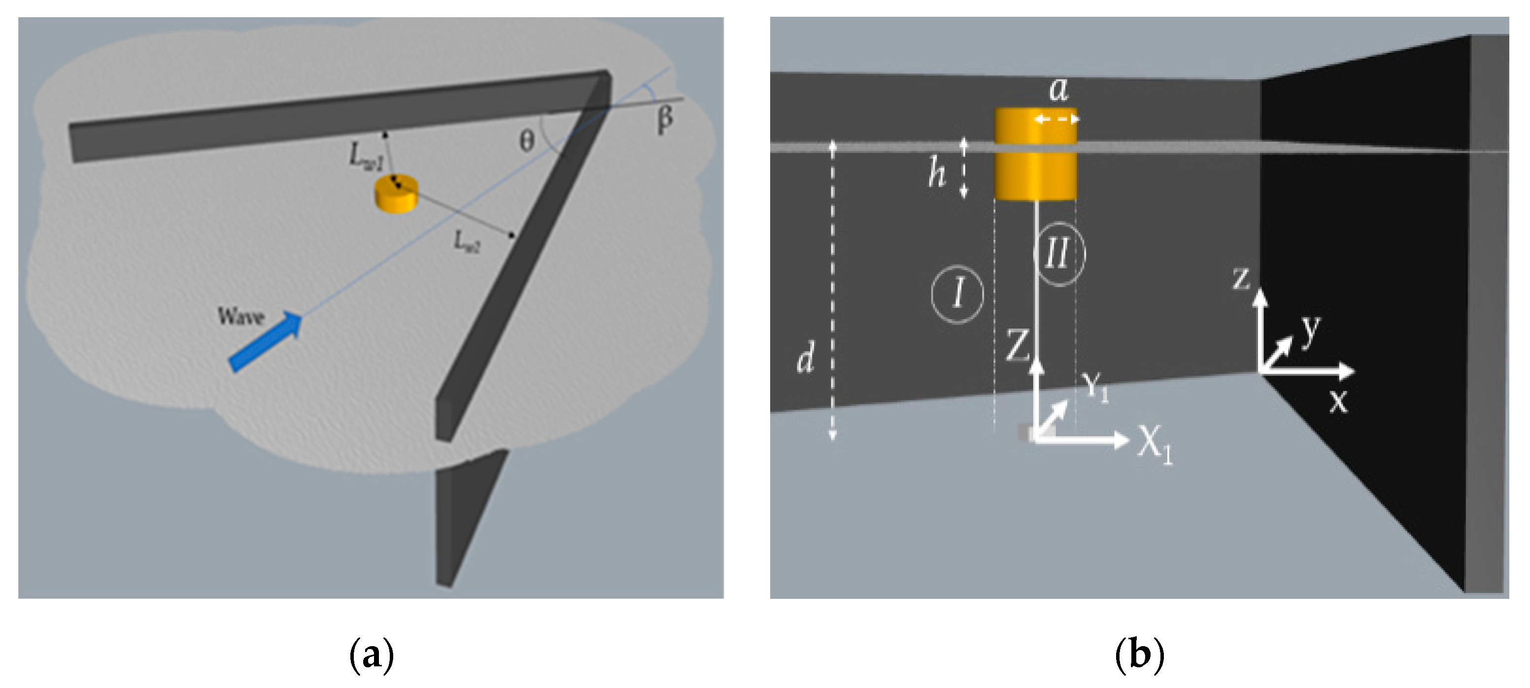
2. Diffraction and Motion Problem Formulation

A vertical cylindrical heaving absorber of radius α and draught h is considered, placed in the interior area of a V-shaped, bottom-fixed, surface-piercing breakwater, of infinite length. The absorber is exposed to small amplitude infinite harmonic waves with angular frequency ω, wave amplitude H/2 and wavelength λ, propagating towards the formed, by the vertical walls, internal breakwater area in constant water depth d. The wave train is incident to the breakwater at an angle β, whereas the vertical walls form an angle of θ. The distances between the vertical axis of the converter and the vertical walls are denoted as Lw1, Lw2. A global Cartesian right-handed co-ordinate system, Oxyz, is introduced, located at the sea bottom, at the connection edge of the two walls with its vertical axis directed upwards. Furthermore, a local cylindrical co-ordinate system is introduced, located at the intersection (X1, Y1) of the seabed with the converter’s vertical axis of symmetry (see Figure 1). The converter is assumed to move only in heave direction, j = 3, being restrained in the other motions, j = 1,2,4,5.
An inviscid, incompressible and irrotational flow is assumed so that the linear potential theory can be employed. The velocity potential in the fluid domains surrounding the absorber can be expressed as:
Φ ( r , θ , z ; t ) = Re [ ( φ I + φ B + φ 3 ) e i ω t ]
In Equation (1), the velocity potential, Φ ( r , θ , z ; t ) = R e [ φ ( r , θ , z ) e i ω t ] , is decomposed into three terms: (a) the incident, φ I , (b) the scattered, φ B , velocity potentials and (c) the radiated potential, φ 3 , of the wave field induced by the oscillation of the absorber in the heave direction.
The velocity potentials φ j ,   j = I , B , 3 have to satisfy the Laplace equation within the entire fluid domain and the linearized boundary conditions at the sea surface, i.e.,:
ω 2 φ j + g φ j z = 0 ,   on   z = d
Furthermore, the potentials φ j have to satisfy the kinematic boundary conditions on the seabed and on the wetted surface of the converter, i.e.,:
φ j z = 0 ,   on   z = 0
φ B n = φ I n , φ j n = i ω ξ j 0 n j ,   j = 3
In Equation (4), the term (   ) n denotes the derivative in the direction of the outward unit normal vector n , to the mean wetted surface on the converter, whereas n j stands for the generalized normal components defined as: n = ( n 1 , n 2 , n 3 ) . The term ξ 30 denotes the heave translatory motion of the converter, i.e.,: ξ j = Re { ξ j 0 e i ω t } ,   j = 3 .
Additionally, φ have to satisfy the no-flux boundary condition on the breakwater’s surface (i.e., along the two arms of the vertical wall) [34]:
φ k = 0  
Here, k stands for the normal vector to the breakwater’s wetted surface.
Finally, a radiation condition must be imposed, stating that propagating disturbances must be outgoing.
The diffraction and radiation velocity potentials of the flow field around the converter in front of the breakwater can be expressed as:
φ D = φ I + φ B = i ω H 2 m = i m Ψ D , m ( r , z ) e i m θ  
φ 3 = i ω ξ 30 m = Ψ 3 , m ( r , z ) e i m θ  
In the present configuration, the diffraction and radiation problems of a converter in front of a V-shaped breakwater are tackled by assuming fully reflecting and infinite long breakwaters forming an angle θ, in order to apply the method of images. The problem of a single WEC in front of a linear breakwater (i.e., θ = 180 degrees) is equivalent to the one of two WECs (i.e., the initial and its mirror device) placed symmetrically in the fluid domain, with respect to the breakwater, without the presence of the vertical wall (see Figure 2a) [9,10]. Similarly, the problem of a WEC in front of an orthogonal breakwater (i.e., θ = 90 degrees) is equivalent to the one of four converters (i.e., the initial one and three mirror bodies). The converters are placed symmetrically with respect to the two arms of the orthogonal wall without the presence of the walls [24,25] (see Figure 2b). Concerning these angle configurations (i.e., θ = 180, 90 degrees), the image method has been shown to accurately describe the corresponding problems compared to finite-length-breakwater arrangements [19,24]. For a V-shaped breakwater forming a random angle θ, however, the method of images attains limitations. Specifically, the method can be applied for angles θ, in which the ratio 360 θ attains integer and even values. Hence, the examined problem of a converter in front of a V-shaped breakwater is equivalent to the one of N converters, i.e., N = 360 θ placed symmetrically with respect to the two arms of the wall, in the fluid domain, without the presence of the vertical wall. Indicatively, in Figure 2c–e, the equivalent array of N converters is depicted, after applying the method of images to tackle the problem of a converter in front of a V-shaped breakwater, forming an angle, θ = 30, 45, 60 degrees, respectively.
By accounting for of the array of N converters, the velocity potential in the fluid domains surrounding the q absorber of the array, q = 1,…,N, can be written, based on Equation (1), as:
φ q ( r q , θ q , z ) = φ Ι ( r q , θ q , z ) + φ Β q ( r q , θ q , z ) + p = 1 N φ 3 q p ( r q , θ q , z )
In Equation (8), φ Β q stands for the scattered wave potential around the q converter, when the latter is considered restrained to the wave impact, originated by the converters of the array, and φ 3 q p denotes the radiation potential of the wave field around the q converter, induced by the forced oscillation of the p body, p = 1,…,N, in the heave direction.
The fluid domain Ω around the converters is assumed to extend to infinity, whereas the volume of the WECs is excluded from Ω. Hence, the underlying boundary value problem can be described by the Laplace equation and Equations (2)–(4), after substituting φ j by φ j q . Specifically, Equation (4) can be rewritten as:
φ B q n p = φ I n p , φ j q p n p = i ω δ q , p ξ 30 q n j q ,   j = 3
Here, δ q , p is the Kronecker’s symbol.
The velocity potential of the corresponding diffraction and radiation problems can be determined by applying the method of matched axisymmetric eigenfunction expansions. Specifically, the flow field around the q converter can be subdivided into coaxial ring-shaped fluid regions, denoted by I and II (i.e., for the outer and lower fluid domain, respectively) (see Figure 1). In these fluid regions, different expansions of the velocity potential are made. These potentials are matched by continuity requirements of the velocity potentials and their radial derivatives along the common vertical boundary surfaces of adjacent fluid regions. Hence, the diffraction and radiation potential in each fluid domain S, S = I, II around the q converter, expressed in its co-ordinate system, can be expressed, in accordance with Equations (6) and (7), as:
φ D q ( r q , θ q , z ) = φ I ( r q , θ q , z ) + φ B q ( r q , θ q , z ) = i ω H 2 m = i m Ψ D , m S , q ( r q , z ) e i m Θ q ,   S = I , II  
φ 3 q p ( r q , θ q , z ) = i ω ξ 30 m = Ψ 3 , m S , q p ( r q , z ) e i m θ q ,   S = I , II  
In Equations (10) and (11), the terms Ψ D , m S , q , Ψ 3 , m S , q p stand for the principal unknowns of the problem in the form of Fourier series.
In order to solve the corresponding diffraction and radiation problems, as described by Equations (10) and (11), the multiple scattering approach is implemented. According to this formulation, the incident velocity potential and the various orders of scattered and radiated waves by the array of WECs are superposed so that exact representations of the wave field around each converter can be obtained. Since the boundary conditions on each converter are satisfied successively without retaining, simultaneously, the partial wave amplitudes around all the WECs of the array, the method requires low computer storage capacity. Here, it should be mentioned that for the velocity potential of the outer domain, i.e., S = I, the condition r q l q p (i.e., l q p denotes the radial distance between the converters q and p) applies, which is imposed by the Bessel function additional theorem [35], used for the determination of the φ D q   and φ 3 q p terms. The method has been analytically described in [36,37] for the solution of the diffraction and the motion-induced radiation problems of an array of vertical axisymmetric bodies, so it is not elaborated on any further here.
Combining the above, the wave field in the outside and lower fluid domain of each converter, q, q = 1,…., N, described by the terms Ψ D , m S , q , Ψ 3 , m S , q p , is evaluated. Analytical representations of the diffraction and radiation velocity potential for each domain S = I, II are presented in the Appendix A.

3. Hydrodynamic Forces

Having determined the velocity potential of the q converter in each fluid domain S = I, II, the various hydrodynamic forces on each body can be determined from the pressure distribution on its wetted surface given by the linearized Bernoulli’s equation, i.e.,
F D , i q = i ω ρ S q φ D q n i d S ,     q = 1 , ,   N
F i , 3 q p = i ω ρ S q φ 3 q p n i d S = i ω ( a i , 3 q p + i ω b i , 3 q p ) ξ ˙ 30     q , p = 1 , ,   N
Here, the φ D q ,     φ 3 q p terms are presented in Equations (10), (11); ρ stands for the water density, S q is the mean wetted surface of the q converter and a i , 3 q p , b i , 3 q p are the added mass and the damping coefficients, respectively, of the q WEC in the i-th direction due to the forced oscillation of the p converter in the heave direction.
For the determination of the exciting forces and moments induced on a WEC in front of a V-shaped breakwater forming a random angle θ and exposed to the action of regular waves propagating at an angle β, the method of images is followed. Specifically, concerning the first order exciting forces on a WEC placed in front of a vane-type breakwater (i.e., θ = 180 degrees), these are equal to the sum of the exciting forces acting on the initial converter for wave trains propagating at angles β and 360 − β, assuming the presence of the image converter, with respect to the breakwater, without the presence of the wall [9]. Furthermore, the exciting forces on a WEC in front of an orthogonal breakwater (i.e., θ = 90 degrees) are equal to the sum of the corresponding forces acting on the initial converter for wave angles β, 360 − β, 2θ − β and 2θ + β, assuming the presence of the four bodies (see Figure 2b) in unbounded waters (i.e., no breakwater) [24]. Regarding, the forces on a WEC in front of a vertical wall forming an angle θ = 60 degrees, these are equal to the sum of the forces on the initial converter, assuming six propagating waves at angles, β, 360 − β, 2θ − β, 2θ + β, 360 − (2θ + β) and 360 − (2θ − β). Hence, the exciting forces, F D , i 1 ,   i = 1 , .. , 5 , on a WEC in front of a vertical wall forming a random angle θ, are equal to the sum of the corresponding forces on the initial WEC under the superposition of N number of propagating waves β’.
F D , i 1 = β = 1 N F D , i 1 , β ,   i = 1 , ,   5
In Equation (14), the term F D , i 1 , β stands for the exciting forces on the initial converter, assuming the presence of N – 1 mirror bodies, for wave heading angle β .
In Table 1 the considered wave train angles, β , are presented for various values of breakwater-angles θ, assuming 20 degrees as a minimum value of θ. This minimum value of θ has been adopted since a WEC in front of a breakwater forming an angle lower than 20 degrees, for amplified wave power absorption, has no physical meaning.
Concerning the hydrodynamic coefficients, A i , 3 11 , B i , 3 11 , in the i-th direction of the WEC in front of the wall, due to its motion in the heave direction, they can be derived by using the same image method formulation as for the exciting forces case. Specifically, the terms A i , 3 11 , B i , 3 11 are equal to the hydrodynamic coefficients, a i , 3 11 , b i , 3 11 , of the initial converter in the i-th direction due to its forced oscillation in heave, assuming the presence of N – 1 mirror converters, superposed by the corresponding coefficients a i , 3 1 p , b i , 3 1 p on the initial converter in the i-th direction due to the forced oscillation in heave of the p image converters, p = 1,…, N – 1, i.e.,
A i , 3 11 = p = 1 N a i , 3 1 p ,   i = 1 , ,   5
B i , 3 11 = p = 1 N b i , 3 1 p ,   i = 1 , ,   5

4. Wave Power Absorption

Based on the presented analysis, the investigation of the equilibrium of the forces acting on a WEC in front of a V-shaped breakwater leads to the following system of differential equations:
( m k 3 + A i , 3 11 ) ξ ¨ 30 + ( B i , 3 11 + B p t o ) ξ ˙ 30 + C k 3 ξ 30 = F D , k 1
In Equation (17), the terms m k 3 , C k 3 denote the mass and stiffness matrix of the converter; the terms F D , k 1 and A i , 3 11 ,   B i , 3 11 have been presented in Equations (14)–(16). In the present configuration, the wave power by the WEC is assumed to be absorbed by a power take off mechanism, which is modelled as a linear damping system, with the damping coefficient B p t o actuated from the heave motion of the WEC.
In order to determine the unknown terms   F D , k 1 , A i , 3 11 ,   B i , 3 11 in Equation (17), which expresses the governing equation in heave motion of the initial converter in front of a V-shaped breakwater with vertical walls, the method of images has been applied as presented in the previous sections. Hence, the scattered and radiated waves from the N bodies of the array, simulating the effect of the breakwater on the WEC hydrodynamics, are properly accounted for.
The wave power absorbed by the converter in front of the breakwater is equal to:
P ( ω ) = 1 2 B p t o ω 2 | ξ 30 | 2
In examining whether the effect of the breakwater on the absorbed wave power is constructive or destructive, the q factor as presented in [38] is applied; i.e.,:
q ( ω ) = P ( ω ) P i s o l ( ω )
Here, P i s o l stands for the absorbed power by a similar WEC in unbounded waters (i.e., no presence of a breakwater). For q ( ω ) greater to unity, the vertical walls have a constructive effect on the WEC’s absorbed power. Contrastively, for q ( ω ) < 1 , the WEC operates more efficiently in the open sea.

5. Numerical Results

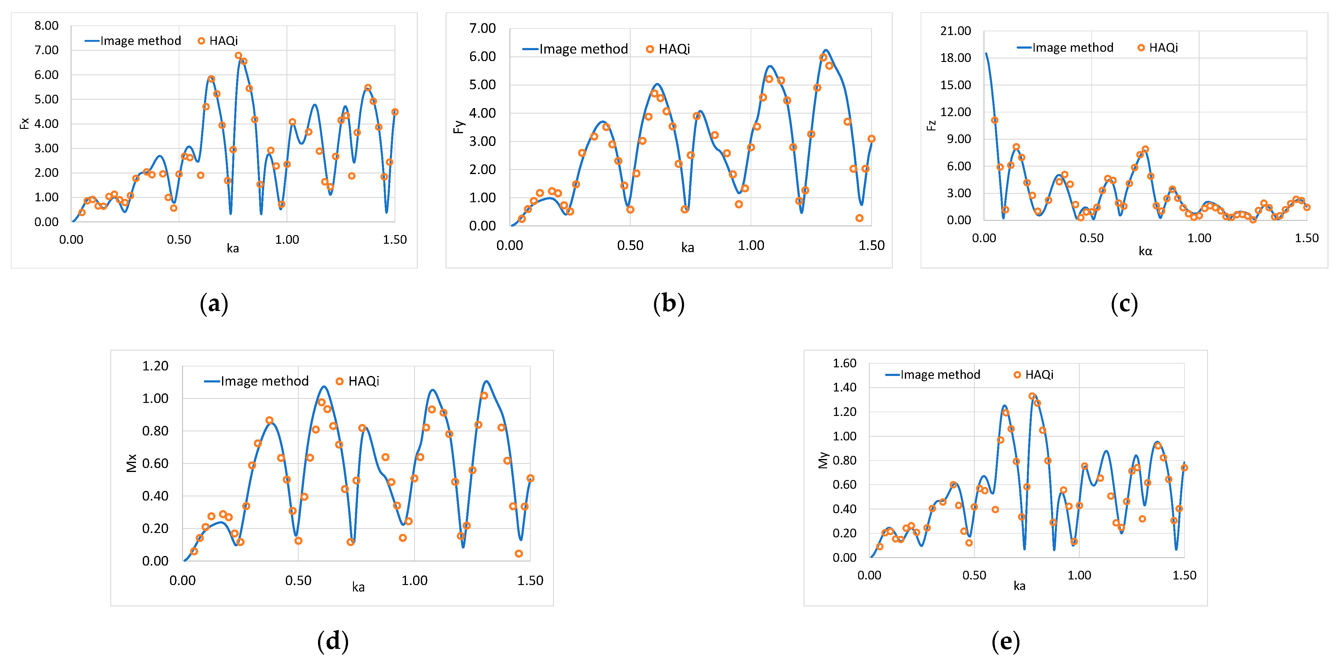
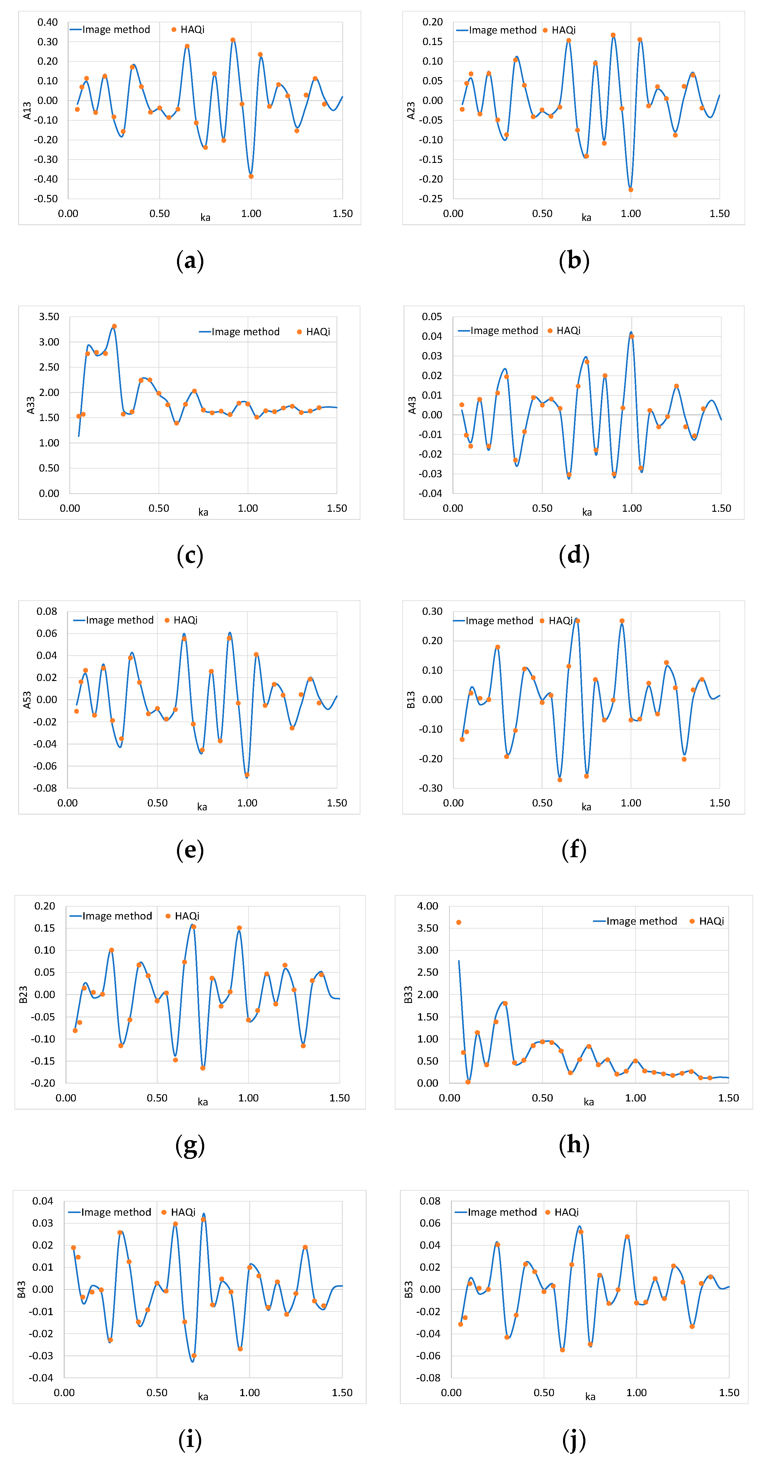
5.1. Result Validation

Based on the theory presented in the following sections, extensive computations have been carried out concerning the hydrodynamics of a WEC in front of a V-shaped breakwater of infinite length. Herein, the in-house computer software HAMVAB (hydrodynamic analysis of multiple vertical axisymmetric bodies) have been used [39].
A cylindrical WEC of radius α is assumed, placed in front of the walls. The walls are surface-piercing and bottom-seated at a water depth d = 2α. The distance between the bottom of the converter and the seabed is equal to dh = 1.2α, whereas the distances between the WEC’s vertical axis and the breakwater’s walls are Lw1 = Lw2 = 13.2α; i.e., the intersection of the WEC’s vertical symmetry axis with the free surface lies on the bisector of the breakwater angle. The center of gravity lies at 0.388α below the free water surface. The mass of the converter is assumed to be equal to the mass of the displaced fluid and the B p t o term is equal to the heave radiation damping of a similar isolated converter at its heave natural frequency. Since the aim of the present work is not to examine the effect of the PTO damping values on the WEC’s performance, the B p t o term is assumed to be constant to the wave conditions.
The accuracy of the method of images for a vane-type and an orthogonal breakwater has been confirmed in [10,24] comparing the outcomes from the method with experimental results and available data from the literature. Since no available results for a V-shaped breakwater-WEC system can be found, the followed methodology is validated against the outcomes from the numerical analysis of a V-shaped breakwater of finite length. The analysis relies on the boundary integral equation method for the velocity potential representation around the vertical walls and the WEC, which is numerically realized using the panel software HAQi [40] that employs sink-sources distribution over the wetted surfaces of the breakwater-WEC system as presented in [41,42].
For the numerical analysis, 4920 elements have been used (i.e., 840 elements for the converter’s discretization and 4080 elements for the discretization of the vertical walls), whereas the examined walls’ length is assumed to be equal to 100α. Here, the formed angle by the walls is θ = 60 degrees, whereas the examined wave heading angle β = 20 degrees.
Figure 3 and Figure 4 depict the exciting forces and moments and the hydrodynamic coefficients, respectively, of the converter placed in front of a 60-degree V-shaped breakwater, using the method of images. The results are compared with the finite walls length case. The exciting forces Fx, Fy, Fz and moments Mx, My are normalized by the terms (ρ2(H/2)) and (ρ3(H/2)), respectively. Additionally, the presented added mass and damping coefficients, Ai3, Bi3, I = 1,…,5 are normalized by (ρα3) and (ρωα3), respectively, for   i 3 and (ρα4), (ρωα4), for i > 4 (see Equations (15), (16)). In addition, in Figure 5, the converter’s heave motions, ξ30, derived from the image method, are compared with the corresponding ones for the finite walls length case. Here, ξ30 is normalized by the wave amplitude H/2, whereas B p t o is assumed to be equal to zero.
It can be seen from Figure 3 that the results of the present formulation (i.e., method of images) correlate excellently to the outcomes of the numerical analysis. It should be noted that some depicted deviations between the results of the two methods, at wave numbers in which the exciting forces attain peaks, should be considered negligible since the numerical results are in absolute accordance with the variation pattern of the outcomes from the method of images. In a similar manner, an excellent comparison between the hydrodynamic coefficients from the method of images and the numerical formulation is notable in Figure 4, as well as in Figure 5 concerning the WEC’s heave motion. Hence, it can be concluded that the present formulation can effectively simulate the effect that a V-shaped vertical breakwater has on the hydrodynamics of a WEC placed in front of it.

5.2. Effect of the Incoming Wave Train Angle

The effect of the wave heading angle on the absorbed wave power by a WEC in front of a V-shaped breakwater is examined in the present subsection. Herein, the examined converter is the same as in Section 5.1, and the breakwater’s formed angle is θ = 60 degrees. The B p t o term is equal to the heave radiation damping of a similar isolated converter at its heave natural frequency (ω ≈ 1.2 rad/s), i.e., B p t o = 0.485 ρ ω α 3 . The WEC’s performance for several wave heading angles, i.e., β = 0, 20, 30 degrees, is presented and compared in order to investigate their effect on the WEC’s efficiency. In Figure 6, the WEC’s heave motions, ξ30/(H/2), and the q factor as defined by Equations (17), (19), are depicted.
It can be seen from Figure 6a that the WEC’s heave motion attains an oscillatory behavior, regardless of the wave heading angle. This is due to the number of converters (i.e., six bodies) and the number of the wave trains (i.e., six wave trains propagating at six different angles) which generate amplified scattered and radiated waves between the bodies of the array. Furthermore, it should be noted that the heave motions for β = 20, 30 degrees, start their variation from values tending to be 6 (at kα tending to zero). On the other hand, for β = 0 degrees, the ξ30 values begin from 4, since wave trains propagating in an angle of β = 0 degrees, i.e., along the x-axis, are not primarily reflected on the breakwater’s wall, which is parallel to the wave train propagation direction. Therefore, for a 60-degree formed-angle, between the walls, only four wave trains are considered (instead of six, see Table 1), i.e., β = 0, 360, 120, 240 degrees. A similar situation holds for β = 60, i.e., waves propagating in a parallel direction to the other wall’s arm. The same conclusion has been derived in [25] when a WEC in front of an orthogonal breakwater was interacting with an incoming wave of β = 0, 90 degrees. Concerning, the effect of the V-shaped breakwater on the WEC’s efficiency, it can be seen from Figure 6b that the vertical walls have, in general, a constructive effect on the WEC’s absorbed power. The range of wave frequencies in which the values of q are higher than unity is wider than the corresponding one for q < 1. However, in numerous wave frequencies, the WEC in front of the breakwater is less efficient than an isolated converter. Hence, it can be concluded that the amplified scattered and radiated waves due to the presence of the vertical wall are not always beneficial to wave power absorption. As far as the effect of the wave heading angle on the WEC’s efficiency is concerned, an optimum wave angle which greatly improves the power absorption ability of the converter in all the examined wave frequencies cannot be established since for each examined angle β the q values oscillate around unity.

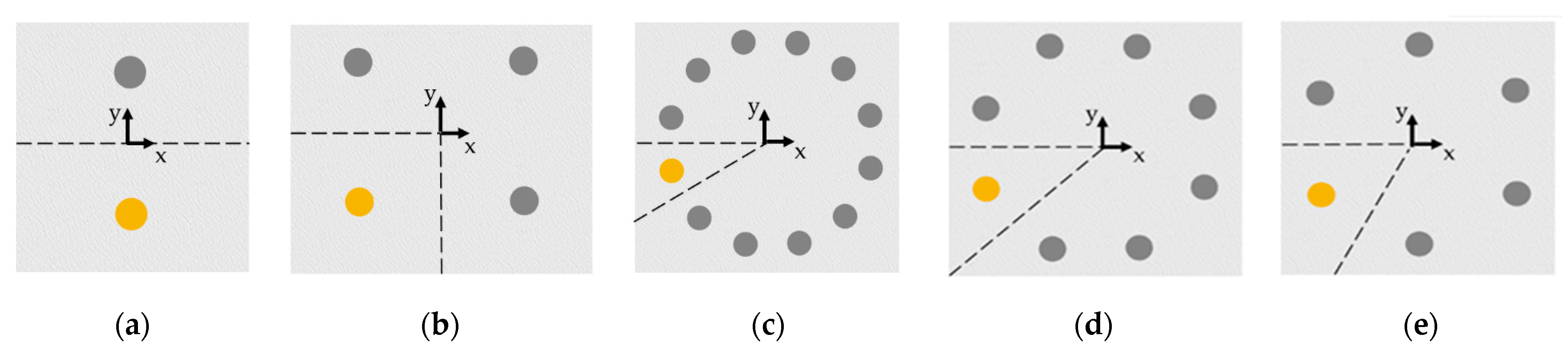
5.3. Effect of the Formed Angle by the Breakwater

The effect of the formed angle by the breakwater on the WEC’s wave power efficiency is shown in the next figures, where different values of θ are examined, i.e., θ = 180, 90, 60, 45 degrees. The WEC’s geometric and PTO characteristics are the same as in Section 5.2, whereas the wave heading angle β is assumed to be equal to 20 degrees. In Figure 7, the WEC’s normalized heave motions, ξ30, and the q factor are depicted. It can be seen that the formed angle by the two wall’s arms significantly affects the WEC’s efficiency. Specifically, it is depicted that the WEC’s heaving motion attains an oscillatory variation pattern for the entire range of wave numbers. However, as θ decreases, these oscillations become more tense. Furthermore, for θ = 180 degrees, the variation of ξ30 begins from the limiting value of ~2 at kα tending be to zero (i.e., two times higher than the limiting value of an isolated WEC, no presence of the wall). For θ = 90 degrees, the limiting value of ξ30 increases to 4, whereas, for θ = 60, 45 degrees, the ξ30 beginning values tend to be ~6 and ~8, respectively. The above trends are introduced due to the amplified wave interactions as the breakwater’s angle decreases, also causing an increase in the WEC’s heave motion. However, the effect of small angles θ on the heave motion is not always constructive. Comparing the ξ30 values for θ = 45 and 180 degrees, it can be seen that the ξ30 for θ = 180 attains larger values at specific wave numbers in which the corresponding heave motions for θ = 45 minimize. Concerning the effect of the breakwater’s angle to the WEC’s efficiency, Figure 7b shows that the lower the formed angle is, the higher the absorbed power by the converter. The results demonstrate clearly that the presence of the wall increases the WEC’s efficiency, irrespective of the formed angle by the vertical walls, since q > 1 at a wide range of wave numbers. This enhancement is sharper for smaller angles θ where the q values oscillate larger, and smoother for higher values of θ where the variation of q values follows a continuous smooth pattern.

5.4. Effect of the WEC (Wave Energy Converter)’s Distance from the Breakwater’s Walls

The effect of the WEC distance from the breakwater’s walls on the WEC’s performance (i.e., heave motions and wave power efficiency) is shown in Figure 8. The converter’s geometric and PTO characteristics are the same as in Section 5.3, whereas the wave heading angle β = 20 degrees and the angle formed by the walls θ = 60 degrees. The WEC is assumed to be equidistant from the walls, i.e., Lw1 = Lw2. Herein, three different distances are examined, i.e., Lw1 = Lw2 = 13.2α, 33.2α, 53.2α. It can be seen from Figure 8a that by decreasing the converter’s distance from the wall, the WEC’s heave motion attains higher values for kα tending to be zero. However, as kα increases, the above trend is not followed. It is obvious that the heave motion exhibits an oscillatory behavior, regardless of the WEC-breakwater distance. Specifically, the larger the distance from the wall is, the more tense the oscillations of the heave motions are. Analogous conclusions can be drawn for the converter’s power efficiency (see Figure 8b). For small values of wave numbers, the 13.2α distance case attains higher power efficiency values compared to the 33.2α 53.2α cases. On the other hand, for higher values of kα, the q factor oscillates around unity. The larger the distance between the wall and the converter is, the more tense the q oscillations are. Compared to the isolated WEC (no presence of the wall), the results of Figure 8b illustrate that the presence of the wall is constructive (i.e., q > 1) in the majority of the examined wave frequency range. More specifically, when the WEC is placed near the wall (i.e., 13.2α), the converter’s efficiency follows a smoother variation pattern compared to the 33.2α and 53.2α cases, while q < 1 at a wider range of wave frequencies. On the other hand, when the converter is placed further from the wall, the WEC’s efficiency exhibits sharp oscillations, while q < 1 in a narrow range of wave frequencies.
Next, the examined converter is assumed to be equidistant from the walls, placed at a closer distance from the breakwater, i.e., Lw1 = Lw2 = 2α, for the same angles β and θ (i.e., β = 20° and θ = 60°). Based on the method of images, the problem is equivalent to the one of six converters placed symmetrically with respect to the two arms of the wall, without the presence of the breakwater. Hence, the distance between the centers of adjacent converters equals 4α.
Furthermore, the above configuration of the six cylinders is investigated as an array of WECs in unbounded waters at a water depth d = 2α (Figure 9), i.e., without the presence of the walls. The array interacts with propagating waves of various directions, i.e., β’= 20, 220, 340 degrees, whereas the distance between adjacent converters equals 4α. These types of arrays (i.e., circular arrays consisting of N number of bodies), which are often studied in the literature since they have a clear relevance to the supporting columns of an offshore platform, attain increased exciting forces as the spacing between adjacent bodies is reduced. This phenomenon is so-called near trapping arising from the existence of standing waves trapped in the interior region bounded by the bodies of the array [43,44].
In Figure 10, the ratio, ℓ, of the exciting forces, F x , F z , on the WEC in front of the V-shaped breakwater to the corresponding exciting forces F x i s o l , F z i s o l on the same converter in unbounded waters (i.e., no presence of the breakwater) is presented, i.e., = F x , z F x , z i s o l . The results are compared with the corresponding ratio of the first converter when it is considered part of a circular array of converters (see Figure 9) for angles β’ = 20, 220, 340 degrees. It can be seen that the values of the ratio ℓ differ between the two arrangements, even though the two array configurations are similar. Furthermore, it is depicted that the values of the ratio for the first converter attain a peculiar behavior at kα ≈ 1.4. This is evident for the horizontal and the vertical exciting forces. This peak can be traced back to a near-trapped wave, which is depicted in all the examined β’ values. On the other hand, this peak is not evident to the ℓ values of the WEC in front of the V-shaped breakwater. The simultaneous interaction of six wave trains with the WEC, as formulated by the method of images in the case of the breakwater-WEC system, seems to annul the existence of such peaks; thus, a smooth variation pattern at kα ≈ 1.4 is obtained.

6. Conclusions

In this paper, the performance (hydrodynamic behavior and power absorption) of a WEC placed in front of a bottom-mounted, surface-piercing V-shaped breakwater under the action of regular waves is examined. Based on the method of images, the physical problem is transformed into an imaginary problem of N converters, placed symmetrically to the breakwater, without its presence. The main conclusions from the presented analysis are the following:
  • Compared to a WEC in unbounded waters (i.e., no presence of a breakwater), the deployment of a converter at the formed angle’s inner area of a V-shaped vertical wall amplifies the power absorption. This power efficiency amplification is strongly dependent on: (a) the wave heading angle, (b) the formed by the vertical walls angle and (c) the distance between the WEC and the breakwater.
  • The heave motion of the converter and its power efficiency are increased for values of wave heading angle, β, in the range of (0, θ). On the other hand, for β = 0, or β = θ, i.e., for incident wave directions parallel to either of the breakwater’s walls, the absorbed wave power reduces. From a physical point of view, the efficiency amplification can be related to the enhanced wave interaction phenomena due to the presence of the converters of the array, whereas the reduction in the absorbed power at specific values of β, corresponding to incident wave directions parallel to either of the breakwater’s walls, can be traced back to the fact that in such cases the incident wave train is not primarily reflected on the breakwater’s wall, which is parallel to the incident wave direction.
  • The decrease in the formed by the breakwater angle, θ, enhances the converter’s power absorption ability compared to higher values of θ. However, the effect of the smallest examined breakwater angle (i.e., 45 degrees) on the WEC’s performance is not always constructive, since at specific wave frequencies the θ = 180 degrees, i.e., linear breakwater, seems to operate more efficiently.
  • The installation of the converter at successively larger distances from the breakwater induces enhanced hydrodynamic interactions between the wall and the converter that consecutively increase the WEC’s power absorption ability. However, this is not always true since the wave interaction phenomena are not always constructive at every examined wave frequency.
The present study will be further extended in order to examine the effect of a V-shaped breakwater on the performance of a WEC allowed to move at its six degrees of freedom under the action of regular wave trains. Moreover, the effect of the breakwater on the WEC’s power efficiency, when the latter is placed to the exterior area formed by the breakwater’s arms, will be investigated.

Author Contributions

Conceptualization, D.N.K. and S.A.M.; methodology, D.N.K.; software, S.A.M.; validation, D.N.K.; formal analysis, D.N.K. and S.A.M.; investigation, D.N.K.; resources, D.N.K. and S.A.M.; data curation, S.A.M.; writing—original draft preparation, D.N.K.; writing—review and editing, S.A.M.; visualization, D.N.K.; supervision, S.A.M.; project administration, S.A.M. Both authors have read and agreed to the published version of the manuscript.

Funding

This research received no external funding.

Institutional Review Board Statement

Not applicable.

Informed Consent Statement

Not applicable.

Data Availability Statement

Not applicable.

Acknowledgments

Not applicable.

Conflicts of Interest

The authors declare no conflict of interest.

Appendix A

Herein, analytical representations of the diffraction and radiation potentials at each examined fluid domain S = I, II are presented.
The diffraction velocity potential can be expressed as a superposition of incident and scattered wave field. Hence, for the outer fluid domain I, i.e., r a ,   0 z d , it holds that [36]:
φ D q = i ω H 2 d m = i m [ G D , m , 0 I , q J m ( k r q ) J m ( k a ) + F D , m , 0 I , q H m ( k r q ) H m ( k a ) ] N 0 1 2 cosh ( k z ) e i m θ q i ω H 2 d m = j = 1 i m [ G D , m , j I , q I m ( a j r q ) I m ( a j a ) + F D , m , j I , q K m ( a j r q ) K m ( a j a ) ] N j 1 2 cos ( a j z ) e i m θ q
Furthermore, the radiation potential around the q converter due to the heave motion of the p converter of the array, for the outer fluid domain I, can be written as [37]:
φ 3 q p = i ω H 2 d m = [ G 3 , m , 0 I , q p J m ( k r q ) J m ( k a ) + ( F 3 , m , 0 I , q p + δ q p F 3 , m , 0 I , p )   H m ( k r q ) H m ( k a ) ] N 0 1 2 cosh ( k z ) e i m θ q i ω H 2 d m = j = 1 [ G 3 , m , j I , q I m ( a j r q ) I m ( a j a ) + ( F 3 , m , j I , q p + δ q p F 3 , m , j I , p ) K m ( a j r q ) K m ( a j a ) ] N j 1 2 cos ( a j z ) e i m θ q
In Equations (A1) and (A2), δ q p   is the Kronecker’s symbol, J m is the m-th order Bessel function of first kind, H m stands for the m-th order Hankel function of first kind, K m is the m-th order modified Bessel function of second kind, and I m denotes the m-th order modified Bessel function of first kind. The quantities a j ,   j 1 , are the positive real roots of the transcendental equation:
ω 2 + g a j tan ( a j d ) = 0
Additionally, it holds that:
N 0 1 2 = [ 1 2 [ 1 + sin h ( 2 k d ) 2 k d ] ] 1 2
N j 1 2 = [ 1 2 [ 1 + sin ( 2 a j d ) 2 a j d ] ] 1 2
The terms G D , m , j I , q ,   F D , m , j I , q ,   j [ 0 , ) are both complex vectors, the elements of which are the unknown Fourier coefficients in the I fluid domain.
Concerning the lower fluid domain II, i.e., 0 r a ,   0 z d h the corresponding diffraction and motion radiation potentials can be expressed as [36,37]:
φ D , 3 q , q p = i ω H 2 d m = [ δ q p ξ 30 H 2 ( z 2 0.5 r p 2 2 ( d h ) ) + F m , 0 I I , q R m , 0 I I + n = 1 2 F m , n I I , q R m , n I I cos ( n π z d h ) ] e i m θ q
Here,
F m , n I I , q = i m F D , m , n I I , q + ξ 30 H 2 ( F 3 , m , n I I , q p + δ q p F 3 , m , n I I , p )
R m , n I I = I m ( n π r d h ) I m ( n π a d h ) ,   m , n 0 ;   R m , 0 I I = ( r a ) m , m 0 ,   n = 0 ;   R 0 , 0 I I = 1 ,   m , n = 0
The term F m , n I I , q ,   j [ 0 , ) stands for a complex vector, the elements of which are the unknown Fourier coefficients in the II fluid domain.

References

  1. Wave Energy Market by Technology, Location, Application and Region—Global Forecast to 2025. Available online: https://www.marketsandmarkets.com/ (accessed on 30 June 2021).
  2. Mustapa, M.A.; Yaakob, O.B.; Ahmed, Y.M.M.; Rheem, C.K.; Koh, K.K.; Faizul, A.A. Wave energy device and breakwater integration: A review. Renew. Sustain. Energy Rev. 2017, 77, 43–58. [Google Scholar] [CrossRef]
  3. Zhao, X.L.; Ning, D.Z.; Zou, Q.P.; Qiao, D.S.; Cai, S.Q. Hybrid floating breakwater-WEC system: A review. Ocean Eng. 2019, 186, 106126. [Google Scholar] [CrossRef]
  4. Vicinanza, D.; Di Lauro, E.; Contestabile, P.; Gisonni, C.; Lara, J.; Losada, I. Review of innovative harbor breakwaters for wave-energy conversion. J. Waterw. Port Coast. Ocean Eng. 2019, 145, 03119001. [Google Scholar] [CrossRef]
  5. Renewable Technology. Available online: https://reneable-technology.com/projects/mutriku-wave-energy-plant/ (accessed on 30 June 2021).
  6. SINNPower. Available online: https://sinnpower.com (accessed on 30 June 2021).
  7. Mccartney, B.L. Floating breakwater design. J. Waterw. Port Coast. Ocean Eng. 1985, 111, 304–318. [Google Scholar] [CrossRef]
  8. Loukogeorgaki, E.; Angelides, D. Performance of moored floating breakwaters. Int. J. Offshore Polar Eng. 2005, 15, 264–273. [Google Scholar]
  9. Mavrakos, S.A.; Katsaounis, G.M.; Nielsen, K.; Lemonis, G. Numerical performance investigation of an array of heaving wave power converters in front of a vertical breakwater. In Proceedings of the 14th International Offshore and Polar Engineering Conference (ISOPE 2004), Toulon, France, 23–28 May 2004. [Google Scholar]
  10. Mavrakos, S.A.; Katsaounis, G.M.; Kladas, A.; Kimoulakis, N. Numerical and experimental investigation of performance of heaving WECs coupled with DC generators. In Proceedings of the 9th European Wave and Tidal Energy Conference, Southampton, UK, 5–9 September 2011. [Google Scholar]
  11. Teng, B.; Ning, D.Z. Wave diffraction from a uniform cylinder in front of a vertical wall. Ocean Eng. 2003, 21, 48–52. [Google Scholar]
  12. Teng, B.; Ning, D.Z.; Zhang, X.T. Wave radiation by a uniform cylinder in front of a vertical wall. Ocean Eng. 2004, 31, 201–224. [Google Scholar] [CrossRef]
  13. Zheng, S.; Zhang, Y. Wave diffraction from a truncated cylinder in front of a vertical wall. Ocean Eng. 2015, 104, 329–343. [Google Scholar] [CrossRef]
  14. Zheng, S.; Zhang, Y. Wave radiation from a truncated cylinder in front of a vertical wall. Ocean Eng. 2016, 111, 602–614. [Google Scholar] [CrossRef]
  15. Konispoliatis, D.N.; Mavrakos, S.A.; Katsaounis, G.M. Theoretical evaluation of the hydrodynamic characteristics of arrays of vertical axisymmetric floater of arbitrary shape in front of a vertical breakwater. J. Mar. Sci. Eng. 2020, 8, 62. [Google Scholar] [CrossRef] [Green Version]
  16. Konispoliatis, D.N.; Mavrakos, S.A. Wave power absorption by arrays of wave energy converters in front of a vertical breakwater: A theoretical study. Energies 2020, 13, 1985. [Google Scholar] [CrossRef] [Green Version]
  17. Cong, P.W.; Chen, L.F.; Gou, Y. Hydrodynamic interaction among multiple columns in front of a vertical wall. Ocean Eng. 2020, 197, 106877. [Google Scholar] [CrossRef]
  18. Li, A.J.; Liu, Y. Water wave diffraction and radiation by a submerged horizontal circular cylinder in front of a vertical wall. In Proceedings of the 39th International Conference on Ocean, Offshore and Arctic Engineering, Virtual Conference, 3–7 August 2020. [Google Scholar]
  19. Loukogeorgaki, E.; Chatjigeorgiou, I. Hydrodynamic performance of an array of wave energy converters in front of a vertical wall. In Proceedings of the 13th European Wave and Tidal Energy Conference (EWTEC, 2019), Naples, Italy, 1–6 September 2019. [Google Scholar]
  20. Loukogeorgaki, E.; Chatjigeorgiou, I. Hydrodynamic performance of an array of truncated cylinders in front of a vertical wall. Ocean Eng. 2019, 189, 106407. [Google Scholar] [CrossRef]
  21. Loukogeorgaki, E.; Boufidi, I.; Chatjigeorgiou, I. Performance of an array of oblate spheroidal heaving wave energy converters in front of a wall. Water 2020, 12, 188. [Google Scholar] [CrossRef] [Green Version]
  22. Ning, D.; Teng, B.; Song, X. Analytical study on wave diffraction from a vertical circular cylinder in front of orthogonal vertical walls. Mar. Sci. Bull. 2005, 7, 1–9. [Google Scholar]
  23. Ning, D.; Teng, B. Study on the oscillation of a uniform cylinder in front of two vertical walls intersecting normally. Chin. Eng. Sci. 2003, 5, 84–91. [Google Scholar]
  24. Konispoliatis, D.; Mavrakos, S. Theoretical analysis of a vertical cylindrical floater in front of an orthogonal breakwater. Fluids 2020, 5, 135. [Google Scholar] [CrossRef]
  25. Konispoliatis, D.; Mavrakos, S. Hydrodynamic efficiency of a wave energy converter in front of an orthogonal breakwater. J. Mar. Sci. Eng. 2021, 9, 94. [Google Scholar] [CrossRef]
  26. Masuda, Y. Apparatus for Generating Electrical Power by Wave Energy and Dissipating Waves. Patent No. GB1492427, 16 November 1977. [Google Scholar]
  27. Reslo, D.T.; Briggs, M.J.; Fowler, J.E.; Markle, D.G. Floating “V” Shaped Breakwater. Patent No. US005702203A, 30 December 1997. [Google Scholar]
  28. Briggs, M. Performance Characteristics of a Rapidly Installed Breakwater System; U.S. Army Engineer Research and Development Center: Vicksburg, MS, USA, 2001; p. 248, ERDC/CHL TR-01-13.
  29. Briggs, M.; Ye, W.; Demirbilek, Z.; Zhang, J. Field and numerical comparisons of the RIBS floating breakwater. J. Hydraul. Res. 2002, 40, 289–301. [Google Scholar] [CrossRef]
  30. Miao, G.P.; Cheng, J.S.; You, Y.X.; Wang, J.Q. Wave defending effects of V-type bottom-mounted breakwaters. China Ocean Eng. 2005, 19, 195–204. [Google Scholar]
  31. Chang, K.H.; Tsaur, D.H.; Huang, L.H. Accurate solution to diffraction around a modified V-shaped breakwater. Coast. Eng. 2012, 68, 56–66. [Google Scholar] [CrossRef]
  32. Ding, N.; Yu, J.; Hou, J. Characteristics of dynamic pressure on floating V-shaped breakwater. J. Drain. Irrig. Mach. Eng. 2014, 32, 29–32. [Google Scholar]
  33. Yu, Y.; Ding, N.; Lin, J.; Hou, J. Wave pressure acting on V-shaped floating breakwater in random seas. J. Ocean Univ. China 2015, 14, 975–981. [Google Scholar] [CrossRef]
  34. Yeung, R.W.; Sphaier, S.H. Wave-interference effects on a truncated cylinder in a channel. J. Eng. Math. 1989, 23, 95–117. [Google Scholar] [CrossRef]
  35. Abramowitz, M.; Stegun, I.A. Handbook of Mathematical Functions, 9th ed.; Dover Publications: Mineola, NY, USA, 1970. [Google Scholar]
  36. Mavrakos, S.A.; Koumoutsakos, P. Hydrodynamic interaction among vertical axisymmetric bodies restrained in waves. Appl. Ocean Res. 1987, 9, 128–140. [Google Scholar] [CrossRef]
  37. Mavrakos, S.A. Hydrodynamic coefficients for groups of interacting vertical axisymmetric bodies. Ocean Eng. 1991, 18, 485–515. [Google Scholar] [CrossRef]
  38. Mavrakos, S.A.; McIver, P. Comparison of methods for computing hydrodynamic characteristics of arrays of wave power devices. Appl. Ocean Res. 1997, 19, 283–291. [Google Scholar] [CrossRef]
  39. Mavrakos, S.A. User’s Manual for the Software HAMVAB; School of Naval Architecture and Marine Engineering, Laboratory for Floating Structures and Mooring Systems: Athens, Greece, 1995. [Google Scholar]
  40. Bardis, L.; Mavrakos, S.A. User’s Manual for the Computer Code HAQ; Laboratory for Floating Bodies and Mooring Systems, National Technical University of Athens: Athens, Greece, 1988. [Google Scholar]
  41. Garisson, C.J. Hydrodynamics of a large objects on the sea. Part I: Hydrodynamic analysis. J. Hydronautics 1974, 8, 5–12. [Google Scholar] [CrossRef]
  42. Garisson, C.J. Hydrodynamics of a large objects on the sea. Part II: Motion of free floating bodies. J. Hydronautics 1975, 9, 58–63. [Google Scholar] [CrossRef]
  43. Evans, D.V.; Porter, R. Near-trapping of waves by circular arrays of vertical cylinders. Appl. Ocean Res. 1997, 19, 83–99. [Google Scholar] [CrossRef]
  44. Evans, D.V.; Porter, R. Trapping and near-trapping by arrays of cylinders in waves. J. Eng. Math. 1999, 35, 149–179. [Google Scholar] [CrossRef]
Figure 1. 3-D representation of a heaving WEC (wave energy converter) in front of a V-shaped breakwater of a random angle θ: (a) plane view; (b) side view.
Jmse 09 00833 g001
Figure 2. Plane view of a WEC (wave energy converter) in front of a V-shaped breakwater, using the method of images, for various forming angles θ: (a) θ = 180 degrees; (b) θ = 90 degrees; (c) θ = 30 degrees; (d) θ = 45 degrees; (e) θ = 60 degrees. The image converters are denoted in dark grey and the breakwater as a dashed line.
Jmse 09 00833 g002
Figure 3. Exciting forces and moments on the converter placed in front of a 60-degree V-shaped breakwater. The results of the method of images are compared with the corresponding ones from an analytical formulation assuming a finite-length breakwater: (a) surge exciting forces; (b) sway exciting forces; (c) heave exciting forces; (d) roll exciting moments; (e) pitch exciting moments.
Jmse 09 00833 g003
Figure 4. Hydrodynamic coefficients of the converter placed in front of a 60-degree V-shaped breakwater. The results of the method of images are compared with the corresponding ones from an analytical formulation assuming a finite length breakwater: (a) added mass in surge due to WEC’s (wave energy converter) motion in heave; (b) added mass in sway due to WEC’s motion in heave; (c) added mass in heave due to WEC’s motion in heave; (d) added mass in roll due to WEC’s motion in heave; (e) added mass in pitch due to WEC’s (wave energy converter) motion in heave; (f) damping coefficient in surge due to WEC’s (wave energy converter) motion in heave; (g) damping coefficient in sway due to WEC’s (wave energy converter) motion in heave; (h) damping coefficient in heave due to WEC’s (wave energy converter) motion in heave; (i) damping coefficient in roll due to WEC’s (wave energy converter) motion in heave; (j) damping coefficient in pitch due to WEC’s (wave energy converter) motion in heave.
Jmse 09 00833 g004
Figure 5. Heave motions of a converter placed in front of a 60-degree V-shaped breakwater. The results of the method of images are compared with the corresponding ones from an analytical formulation assuming a finite length breakwater. Here, B p t o = 0 .
Jmse 09 00833 g005
Figure 6. Effect of the V-shaped breakwater on the WEC’s (wave energy converter) performance for various examined wave heading angles β: (a) WEC’s (wave energy converter motions) heave; (b) q factor term. The horizontal solid line corresponds to unity.
Jmse 09 00833 g006
Figure 7. Effect of the V-shaped breakwater on the WEC’s (wave energy converter) performance for various examined formed breakwater angles θ: (a) WEC’s (wave energy converter) heave motions; (b) q factor term. The horizontal solid line corresponds to unity.
Jmse 09 00833 g007
Figure 8. Effect of the V-shaped breakwater on the WEC’s (wave energy converter) performance for various examined WEC’s (wave energy converter) distances from the breakwater: (a) WEC’s (wave energy converter) heave motions; (b) q factor term. The horizontal solid line corresponds to unity.
Jmse 09 00833 g008
Figure 9. Arrangement and converters’ labels for a circular array of six WECs (wave energy converters).
Jmse 09 00833 g009
Figure 10. Ratio, ℓ, of the exciting forces for the WEC (wave energy converter) in front of the V-shaped breakwater and for the first WEC (wave energy converter) of a circular array of six converters: (a) horizontal-exciting-force ratio; (b) vertical-exciting-force ratio.
Jmse 09 00833 g010
Table 1. Wave train directions, β’, (in degrees) for N considered WECs (wave energy converter) and various breakwater angles θ (in degrees).
θ/Nθ = 180θ = 90θ = 60θ = 45θ = 36θ = 30θ = 25.71θ = 22.5θ = 20
1βββββββββ
2360 − β360 − β360 − β360 − β360 − β360 − β360 − β360 − β360 − β
3 2θ + β2θ + β2θ + β2θ + β2θ + β2θ + β2θ + β2θ + β
42θ − β2θ − β2θ − β2θ − β2θ − β2θ − β2θ − β2θ − β
5 360 − (2θ + β)360 − (2θ + β)360 − (2θ + β)360 − (2θ + β)360 − (2θ + β)360 − (2θ + β)360 − (2θ + β)
6360 − (2θ − β)360 − (2θ − β)360 − (2θ − β)360 − (2θ − β)360 − (2θ − β)360 − (2θ − β)360 − (2θ − β)
7 4θ + β4θ + β4θ + β4θ + β4θ + β4θ + β
84θ − β4θ − β4θ − β4θ − β4θ − β4θ − β
9 360 − (4θ + β)360 − (4θ + β)360 − (4θ + β)360 − (4θ + β)360 − (4θ + β)
10360 − (4θ − β)360 − (4θ − β)360 − (4θ − β)360 − (4θ − β)360 − (4θ − β)
11 6θ + β6θ + β6θ + β6θ + β
126θ − β6θ − β6θ − β6θ − β
13 360 − (6θ + β)360 − (6θ + β)360 − (6θ + β)
14360 − (6θ − β)360 − (6θ − β)360 − (6θ − β)
15 8θ + β8θ + β
168θ − β8θ − β
17 360 − (8θ + β)
18360 − (8θ − β)
Publisher’s Note: MDPI stays neutral with regard to jurisdictional claims in published maps and institutional affiliations.

