
Real-Time Nonlinear Model Predictive Controller for Multiple Degrees of Freedom Wave Energy Converters with Non-Ideal Power Take-Off


Abstract
:1. Introduction
2. Time Domain Model of a Multiple Degree of Freedom WEC
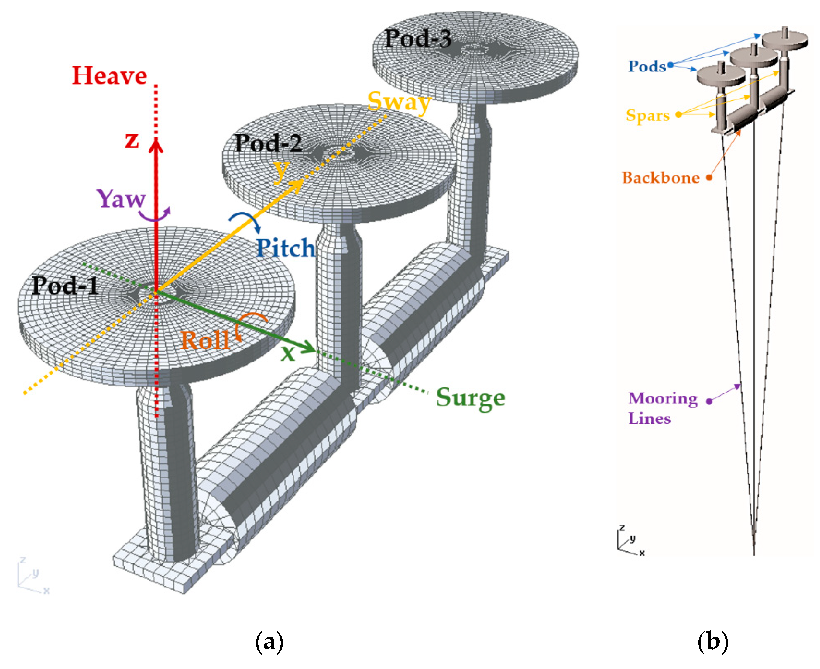
2.1. Surge-Pitch-Heave Model of WEC Modeling in State-Space Form
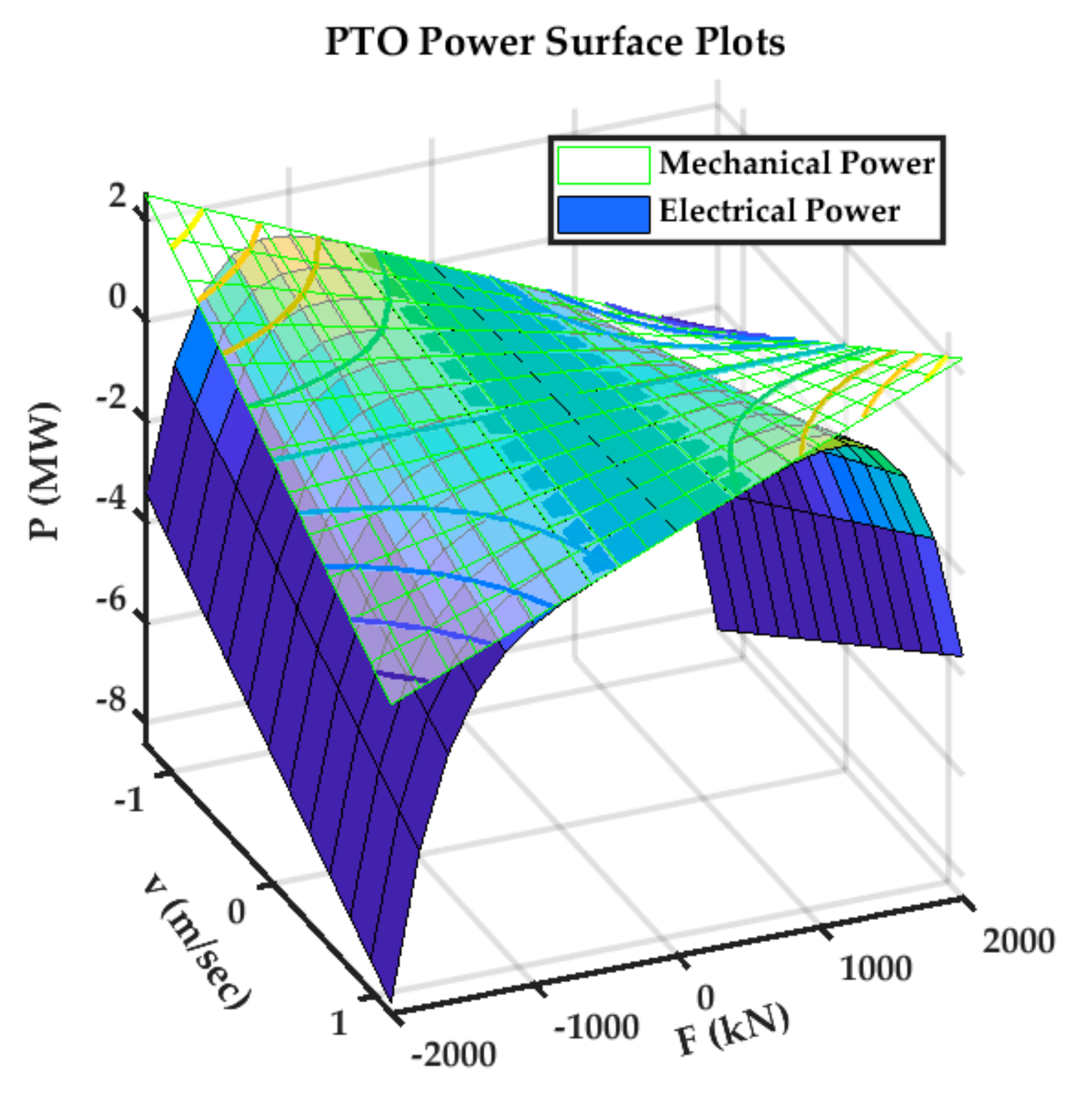
2.2. Nonquadratic WEC-PTO Model
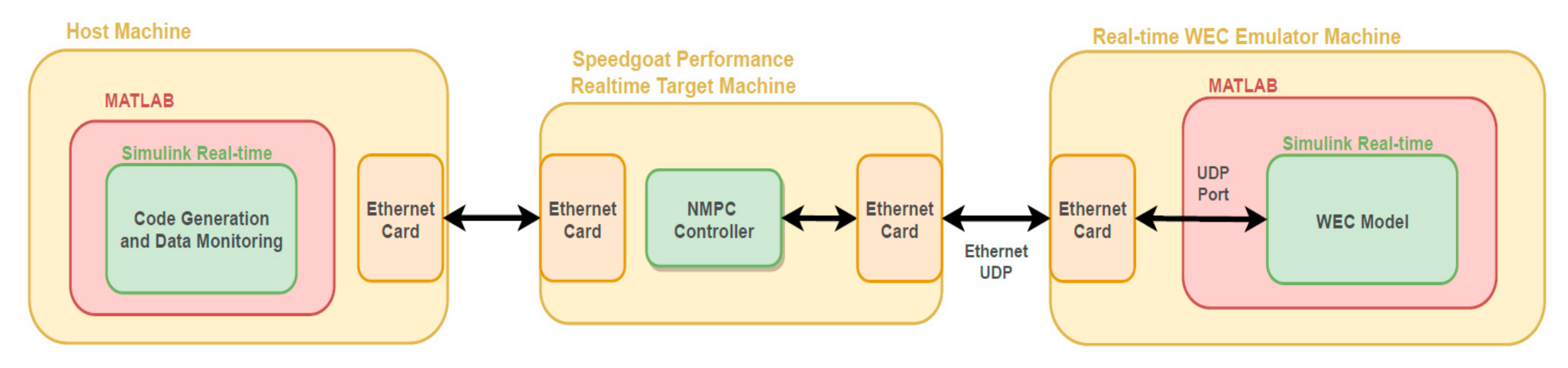
3. Implementation of NMPC for 2-DoF Heave-Pitch WEC
4. Results
5. Discussion
6. Conclusions
Author Contributions
Funding
Institutional Review Board Statement
Informed Consent Statement
Acknowledgments
Conflicts of Interest
References
- Muetze, A.; Vining, J.G. Ocean Wave Energy Conversion—A Survey. In Proceedings of the Conference Record of the 2006 IEEE Industry Applications Conference Forty-First IAS Annual Meeting, Tampa, Fl, USA, 8–12 October 2006; Volume 3, pp. 1410–1417. [Google Scholar]
- Richter, M.; Magana, M.E.; Sawodny, O.; Brekken, T.K.A. Nonlinear Model Predictive Control of a Point Absorber Wave Energy Converter. IEEE Trans. Sustain. Energy 2013, 4, 118–126. [Google Scholar] [CrossRef]
- Haider, A.S.; Brekken, T.K.A.; McCall, A. A State-of-the-Art Strategy to Implement Nonlinear Model Predictive Controller with Non-Quadratic Piecewise Discontinuous Cost Index for Ocean Wave Energy Systems. In Proceedings of the 2020 IEEE Energy Conversion Congress and Exposition (ECCE), Detroit, MI, USA, 11–15 October 2020; pp. 1873–1878. [Google Scholar]
- Brekken, T.K.A. On Model Predictive Control for a Point Absorber Wave Energy Converter. In Proceedings of the 2011 IEEE Trondheim PowerTech, Trondheim, Norway, 19–23 June 2011; pp. 1–8. [Google Scholar]
- Faedo, N.; Olaya, S.; Ringwood, J.V. Optimal Control, MPC and MPC-like Algorithms for Wave Energy Systems: An Overview. IFAC J. Syst. Control 2017, 1, 37–56. [Google Scholar] [CrossRef] [Green Version]
- Zhong, Q.; Yeung, R.W. Model-Predictive Control Strategy for an Array of Wave-Energy Converters. J. Mar. Sci. Appl. 2019, 18, 26–37. [Google Scholar] [CrossRef] [Green Version]
- Genest, R.; Ringwood, J.V. A Critical Comparison of Model-Predictive and Pseudospectral Control for Wave Energy Devices. J. Ocean Eng. Mar. Energy 2016, 2, 485–499. [Google Scholar] [CrossRef] [Green Version]
- Li, G.; Belmont, M.R. Model Predictive Control of Sea Wave Energy Converters—Part I: A Convex Approach for the Case of a Single Device. Renew. Energy 2014, 69, 453–463. [Google Scholar] [CrossRef]
- Li, G.; Belmont, M.R. Model Predictive Control of Sea Wave Energy Converters—Part II: The Case of an Array of Devices. Renew. Energy 2014, 68, 540–549. [Google Scholar] [CrossRef]
- Starrett, M.; So, R.; Brekken, T.K.A.; McCall, A. Increasing Power Capture from Multibody Wave Energy Conversion Systems Using Model Predictive Control. In Proceedings of the 2015 IEEE Conference on Technologies for Sustainability (SusTech), Ogden, UT, USA, 30 July–1 August 2015; pp. 20–26. [Google Scholar]
- Falcão, A.F.O.; Henriques, J.C.C. Effect of Non-Ideal Power Take-off Efficiency on Performance of Single- and Two-Body Reactively Controlled Wave Energy Converters. J. Ocean Eng. Mar. Energy 2015, 1, 273–286. [Google Scholar] [CrossRef] [Green Version]
- Davis, A.F.; Thomson, J.; Mundon, T.R.; Fabien, B.C. Modeling and Analysis of a Multi Degree of Freedom Point Absorber Wave Energy Converter. In Proceedings of the OMAE 2014, San Francisco, CA, USA, 8 June 2014; Volume 8A: Ocean Engineering. [Google Scholar]
- Al Shami, E.; Wang, X.; Ji, X. A Study of the Effects of Increasing the Degrees of Freedom of a Point-Absorber Wave Energy Converter on Its Harvesting Performance. Mech. Syst. Signal Process. 2019, 133, 106281. [Google Scholar] [CrossRef]
- Strager, T.; Martin dit Neuville, A.; Fernández López, P.; Giorgio, G.; Mureşan, T.; Andersen, P.; Nielsen, K.M.; Pedersen, T.S.; Vidal Sánchez, E. Optimising Reactive Control in Non-Ideal Efficiency Wave Energy Converters. In Proceedings of the OMAE 2014, San Francisco, CA, USA, 8 June 2014; Volume 9A: Ocean Renewable Energy. [Google Scholar]
- Perdigão, J.; Sarmento, A. Overall-Efficiency Optimisation in OWC Devices. Appl. Ocean Res. 2003, 25, 157–166. [Google Scholar] [CrossRef]
- Tedeschi, E.; Carraro, M.; Molinas, M.; Mattavelli, P. Effect of Control Strategies and Power Take-Off Efficiency on the Power Capture From Sea Waves. IEEE Trans. Energy Convers. 2011, 26, 1088–1098. [Google Scholar] [CrossRef]
- Jia, Y.; Meng, K.; Dong, L.; Liu, T.; Sun, C.; Dong, Z.Y. Economic Model Predictive Control of a Point Absorber Wave Energy Converter. IEEE Trans. Sustain. Energy 2021, 12, 578–586. [Google Scholar] [CrossRef]
- Ellis, M.; Durand, H.; Christofides, P.D. A Tutorial Review of Economic Model Predictive Control Methods. J. Process Control 2014, 24, 1156–1178. [Google Scholar] [CrossRef]
- Rawlings, J.B.; Angeli, D.; Bates, C.N. Fundamentals of Economic Model Predictive Control. In Proceedings of the 2012 IEEE 51st IEEE Conference on Decision and Control (CDC), Maui, HI, USA, 10–13 December 2012; pp. 3851–3861. [Google Scholar]
- Houska, B.; Ferreau, H.J.; Diehl, M. An Auto-Generated Real-Time Iteration Algorithm for Nonlinear MPC in the Microsecond Range. Automatica 2011, 47, 2279–2285. [Google Scholar] [CrossRef]
- Houska, B.; Ferreau, H.J.; Diehl, M. ACADO Toolkit—An Open-Source Framework for Automatic Control and Dynamic Optimization. Optim. Control. Appl. Methods 2011, 32, 298–312. [Google Scholar] [CrossRef]
- Abdelkhalik, O.; Zou, S.; Robinett, R.D.; Bacelli, G.; Wilson, D.G.; Coe, R.; Korde, U. Multiresonant Feedback Control of a Three-Degree-of-Freedom Wave Energy Converter. IEEE Trans. Sustain. Energy 2017, 8, 1518–1527. [Google Scholar] [CrossRef]
- Frequency- and Time-Domain Analysis of a Multi-Degree-of-Freedom Point Absorber Wave Energy Converter–Yizhi Ye, Weidong Chen, 2017. Available online: https://journals.sagepub.com/doi/full/10.1177/1687814017722081 (accessed on 20 July 2021).
- Coe, R.G.; Bull, D.L. Nonlinear Time-Domain Performance Model for a Wave Energy Converter in Three Dimensions. In Proceedings of the 2014 Oceans, St. John’s, NL, Canada, 14–19 September 2014; pp. 1–10. [Google Scholar]
- Huang, S.; Shi, H.; Dong, X. Capture Performance of A Multi-Freedom Wave Energy Converter with Different Power Take-off Systems. China Ocean Eng. 2019, 33, 288–296. [Google Scholar] [CrossRef]
- Hillis, A.J.; Whitlam, C.; Brask, A.; Chapman, J.; Plummer, A.R. Active Control for Multi-Degree-of-Freedom Wave Energy Converters with Load Limiting. Renew. Energy 2020, 159, 1177–1187. [Google Scholar] [CrossRef]
- Li, G. Nonlinear Model Predictive Control of a Wave Energy Converter Based on Differential Flatness Parameterisation. Int. J. Control 2017, 90, 68–77. [Google Scholar] [CrossRef]
- WEC-Sim (Wave Energy Converter SIMulator)—WEC-Sim Documentation. Available online: https://wec-sim.github.io/WEC-Sim/ (accessed on 27 March 2021).
- van Rij, J.; Yu, Y.-H.; McCall, A.; Coe, R.G. Extreme Load Computational Fluid Dynamics Analysis and Verification for a Multibody Wave Energy Converter. In Proceedings of the OMAE 2019, Glasgow, UK, 9–14 June 2019; Volume 10: Ocean Renewable Energy. [Google Scholar]
- Haider, A.S.; Brekken, T.K.A.; McCall, A. Application of Real-Time Nonlinear Model Predictive Control for Wave Energy Conversion. IET Renew. Power Gener. 2021. [Google Scholar] [CrossRef]
- Speedgoat—The Quickest Path to Real-Time Simulation and Testing. Available online: https://www.speedgoat.com/ (accessed on 23 February 2021).
- Ecomerit Technologies. Available online: http://www.ecomerittech.com/centipod.php (accessed on 14 August 2021).
- Wamit, Inc. The State of the Art in Wave Interaction Analysis. Available online: https://www.wamit.com/ (accessed on 28 March 2021).
- Ringwood, J.V. Wave Energy Control: Status and Perspectives 2020 ⁎⁎This Paper Is Based upon Work Supported by Science Foundation Ireland under Grant No. 13/IA/1886 and Grant No. 12/RC/2302 for the Marine Renewable Ireland (MaREI) Centre. IFAC-PapersOnLine 2020, 53, 12271–12282. [Google Scholar] [CrossRef]


| Variable | Description |
|---|---|
| Velocity (Linear or Angular) in DoF | |
| Displacement (Linear or Angular) in DoF | |
| Intermediate State variables for radiation force State-Space approximation | |
| Radiation force in DoF due to velocity in DoF | |
| Hydrostatic force in DoF | |
| Viscous drag force in DoF | |
| Wave excitation force in DoF | |
| PTO force in DoF | |
| m | Mass of the float |
| Added mass at the infinite frequency in DoF due to acceleration in DoF | |
| The hydrostatic restoring coefficient in DoF | |
| Viscous drag coefficient in DoF | |
| Frequency-dependent added mass in DoF due to acceleration in DoF | |
| Frequency-dependent damping in DoF due to velocity in DoF | |
| Radiation force impulse response without infinite frequency added mass | |
| WEC Intrinsic impedance response in DoF due to velocity in DoF | |
| Polynomial coefficients | |
| Polynomial coefficients for cost functional | |
| PTO current | |
| PTO converter efficiency | |
| PTO generator copper loss constant | |
| PTO generator winding resistance |
| Variable | Description |
|---|---|
| Prediction horizon | |
| State vector | |
| Finite horizon terminal cost penalty or Mayer terms | |
| Some Nonlinear functions or Lagrange terms | |
| A column vector of time-varying parameters | |
| PTO Force manipulated variable vector, () | |
| Excitation force disturbance vector, () | |
| Cost functional scheduling variable | |
| Some real numbers, such that |
| WEC-Sim Simulation Parameter | Value |
|---|---|
| Significant Wave Height [m] | 2.5 |
| Peak Period [s] | 8 |
| Wave Spectrum Type | Pierson Moskowitz (PM) |
| Wave Class | Irregular |
| Average Electrical Power [kW] | ||||||
|---|---|---|---|---|---|---|
| Control Algorithm | Linear Hydrodynamic Conditions | Nonlinear Hydrodynamic Conditions | ||||
| Heave | Pitch | Total | Heave | Pitch | Total | |
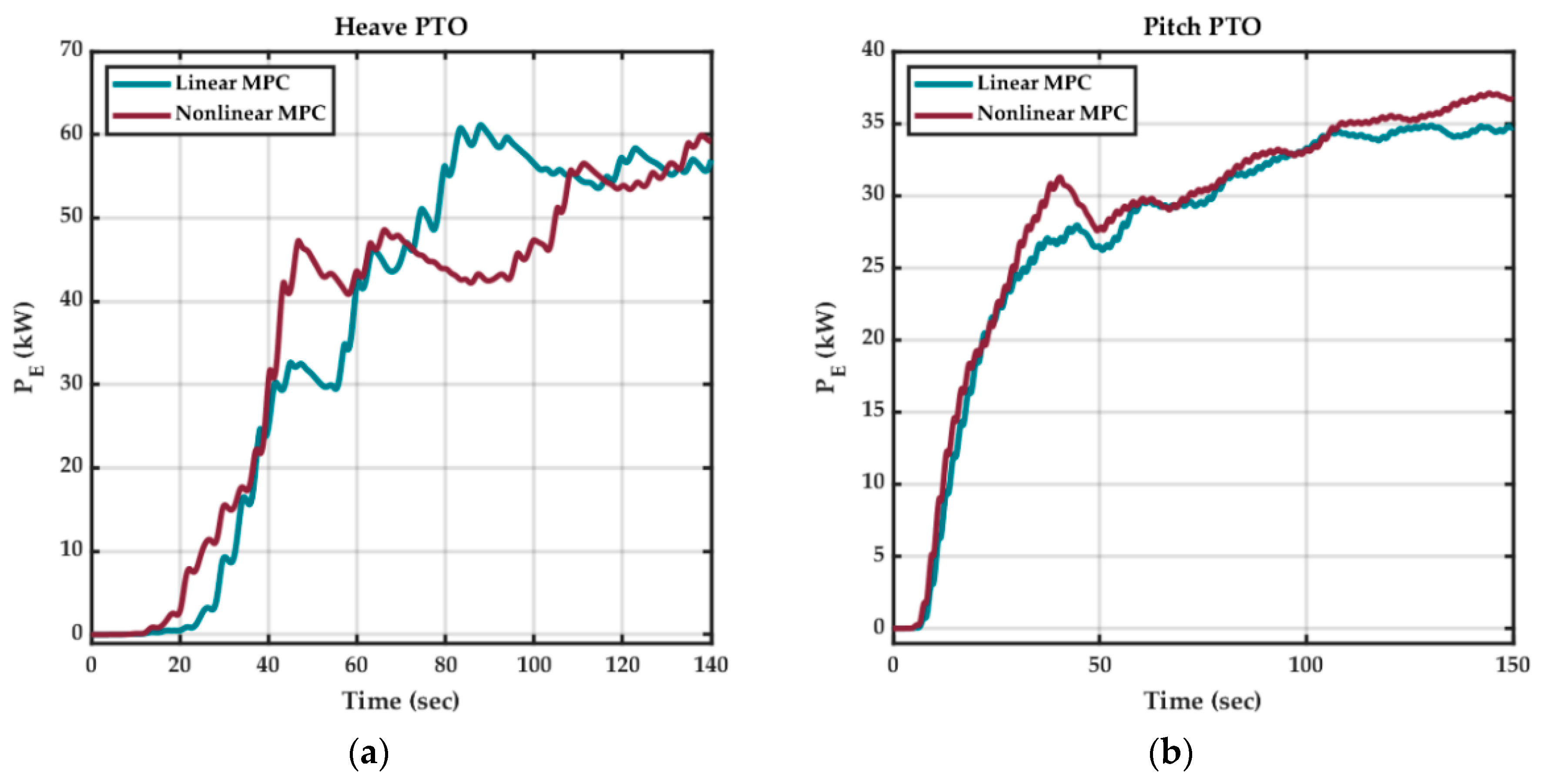
| Linear MPC | 57 | 35 | 92 | 70 | 52 | 122 |
| Nonlinear MPC | 60 | 37 | 97 | 79 | 56 | 135 |
| Task Execution Time (TET) [sec] | |||
|---|---|---|---|
| Control Algorithm | 1-DoF Heave | 1-DoF Pitch | 2-DoF Heave and Pitch |
| Linear MPC | |||
| Nonlinear MPC | |||
| Average Electrical Power [kW] | |||
|---|---|---|---|
| 1-DoF WEC | 2-DoF WEC | ||
| Axis | Heave | Pitch | Heave and Pitch |
| Heave | 98 | 0 | 78 |
| Pitch | 0 | 58 | 55 |
| Net Power | 98 | 58 | 133 |
Publisher’s Note: MDPI stays neutral with regard to jurisdictional claims in published maps and institutional affiliations. |
© 2021 by the authors. Licensee MDPI, Basel, Switzerland. This article is an open access article distributed under the terms and conditions of the Creative Commons Attribution (CC BY) license (https://creativecommons.org/licenses/by/4.0/).
Share and Cite
Haider, A.S.; Brekken, T.K.A.; McCall, A. Real-Time Nonlinear Model Predictive Controller for Multiple Degrees of Freedom Wave Energy Converters with Non-Ideal Power Take-Off. J. Mar. Sci. Eng. 2021, 9, 890. https://doi.org/10.3390/jmse9080890
Haider AS, Brekken TKA, McCall A. Real-Time Nonlinear Model Predictive Controller for Multiple Degrees of Freedom Wave Energy Converters with Non-Ideal Power Take-Off. Journal of Marine Science and Engineering. 2021; 9(8):890. https://doi.org/10.3390/jmse9080890
Chicago/Turabian StyleHaider, Ali S., Ted K. A. Brekken, and Alan McCall. 2021. "Real-Time Nonlinear Model Predictive Controller for Multiple Degrees of Freedom Wave Energy Converters with Non-Ideal Power Take-Off" Journal of Marine Science and Engineering 9, no. 8: 890. https://doi.org/10.3390/jmse9080890