1. Introduction
Saving energy and making the best out of intermittent resources is—and will remain— the first goal in the strategy of the energy industry sector in the years to come. It is more crucial to extract the maximum from the energy resources available and the operating industrial units than to plan and build new plants. There is a compelling need for waste heat recovery from operating units and it is about time the existing waste heat-recovery systems and their characteristics are evaluated.
The excess heat from wind farms (WFs) is characterized by a relatively low thermal content (approx. 90–150 °C) and thus the applications that are best suited for its utilization are mostly related to heating processes than to energy generation. Waste heat can be recovered and be generally used for space and process heating. District heating (DH) can contribute significantly to a more efficient use of energy resources as well as provide better integration of surplus/industrial waste heat and renewable energy into the heating sector.
While district heating might be an apparent application, the agricultural and livestock sector can also benefit significantly by such an application. Greenhouse space heating, produce cooling (absorption cycle) and milk heating (pasteurization process) are just a few of the possible technical uses of the excess heat from WFs. The location of wind turbines (WTs) near rural and agricultural lands is an apparent advantage in this case. The overall advantages of such a system with the use of excess heat from WTs for additional heating purposes which increases the overall system efficiency are going to be tested in detail through engineering analysis and representative case studies.
The need for extracting the maximum output from existing installations is increasing as we continue under the economic crisis. The requirements for increasing the efficiency of energy systems are increasing rapidly towards the “battle” of rationalizing costs. Electricity generation units, industries, warehouses, and even residential buildings are slowly adopting this approach. The leading concept is to extract the maximum output in order to save resources. Currently, this is widely observed in all sectors. It was initially seen and implemented in the energy industry in the Cogeneration sector or combined heat and power (CHP) sector. Trigeneration (CHP including cooling) evolved from CHP systems.
1.1. Insufficient Design Paradigm—Need for Innovation
It is accepted that waste heat means loss therefore finding ways to utilize heat means increased efficiency for a system. Waste heat recovery (WHR) based on thermal or fossil fuel plants is normally expected. WHR from WFs is not the most common case, however, since: (a) WF installations are increasing globally, (b) in many cases, WFs, are installed close to villages or small towns and (c) demand for cheap energy is growing; therefore, WHR ought to be examined thoroughly. Predictability of the wind load should be investigated in order to facilitate end-users’ usage and commitment. Other applications (e.g., agricultural) are also apparently expected.
The idea of using a ground loop heat exchanger in order to dissipate the excess heat of a wind turbine was first proposed in 2007 by G. Pechlivanoglou in the form of the patent document GR 1005990 [
1].
The main principle of this idea was the use of a liquid medium to transport the thermal energy from the turbine nacelle to the ground. A ground loop heat exchanger was proposed in order to provide optimal thermal exchange characteristics. Considering the significant earth-works required for the foundation of a modern wind turbine, the addition of a ground heat exchanger loop adds a relatively small extra cost to the system. Two liquid carrying hoses are driven up from the turbine foundation to the nacelle. These can follow the power cables of the turbine. In their simplest form they would not require any form of rotating connector in order to accommodate the azimuth rotation of the nacelle. They can form a “loop” similar to the one traditionally formed by the power cables and thus allow a degree of twist (approx. 3 full nacelle rotations). Inside the nacelle a collector vessel can collect all of the excess heat of the various components of the turbine (e.g., gearbox, generator, power electronics). The circulation of the heat transfer fluid is achieved using a conventional circulating pump, commonly used for heating systems in commercial buildings (
Figure 1).
Figure 1.
The geothermal cooling principle and thermal heat transport to the ground proposed by G. Pechlivanoglou [
2].
Figure 1.
The geothermal cooling principle and thermal heat transport to the ground proposed by G. Pechlivanoglou [
2].
Using configurations such as the one in
Figure 1, the problem of air-cooling systems can be fully confronted as well. The variability of the atmospheric air temperature has a direct influence on wind turbine air-cooling systems. Low air temperatures lead to effective heat transfer towards the atmosphere.
On the contrary, high atmospheric temperatures delay the heat transfer rate, thus requiring a larger airflow rate in order to achieve comparable heat dissipation. Most wind turbine cooling systems have a maximum ambient temperature level above which they cannot operate to ensure sufficient cooling performance to maintain the design operational temperature for the different components. This leads to gradual de-rating of the power output and eventually to wind turbine shut-down due to an overheating alarm.
1.2. Work Performed thus far on Waste Heat Recovery
The number of researchers working in the WHR field and the number of novel applications are increasing. Safaei
et al. [
3], evaluated the feasibility of compressed air energy storage (CAES) by enabling heat recovery for covering district heating needs. It was proven that a minimum gas price of $0.025/kWh renders heat recovery economically favorable at a 25-km distance versus $0.027/kWh at 50 km. Varbanov and Klemeš [
4] revealed that by combining the supply and demand streams of the individual users, industrial plants, and the residential and service sectors could be served using various energy carriers. Perry
et al. [
5] examined local distributed renewable energy sources focusing on those sources that were able to provide local heating and cooling. Alfegi
et al. [
6] worked with heat recovery units (using fluid circulation) with a photovoltaic/thermal (PV/T) system, proving that the electricity production in a PV/T hybrid module decreases as the temperature of the air flow increases. Therefore, according to demand requirements, electricity and heat production producing in such systems should be co-optimized.
Ambient air is usually laden with dust particles. This effect is especially significant in sandy and desert regions where strong winds are able to suspend and transport sand particles at considerable heights [
7]. At offshore and near-shore wind sites, the wind transports salt through the humidity (water particles) in the air. Both dust and salt can have destructive effect on parts and components. They lead to erosion and wear of moving components and they cause corrosion of various materials. Wind turbine cooling systems and especially the exposed air-heat exchangers are also heavily affected. Sand particles and salt adhere to the surface of the heat exchangers, thus forming an insulating layer and reducing their heat transfer performance. Furthermore, the increased blockage caused by the adhesion of foreign matter on the heat exchangers reduces the flow velocity and further degrades their performance. These environmental and operational challenges have a significant economic influence on the turbine operation and thus on the turbine operation and maintenance costs. It is often demonstrated that a low-cost and low complexity solution, such as a conventional air-cooling system, hides significant costs for the turbine operator, which make it less attractive in the long-run.
The challenges posed for the cooling of the turbine have lead to the development of more sophisticated cooling systems and an increase in the number and size of the cooling components. Currently, a large portion of wind turbine nacelles houses the cooling system components. Considering the limited available nacelle space and the increased loads on the tower and foundation due to a higher tower-top weight, it is clear that an optimal design of the cooling systems might be necessary.
One solution for this problem is the aerodynamic optimization of existing air-cooling components (
Figure 2).
Figure 2.
CFD simulation of a wind turbine nacelle with an optimized configuration (right) and a sub-optimal air-cooling system location (left).
Figure 2.
CFD simulation of a wind turbine nacelle with an optimized configuration (right) and a sub-optimal air-cooling system location (left).
In this case, the placement and design of the heat exchangers, inflow ducts, fans and outlets undergoes sophisticated fluid dynamic analysis and optimization. The results of such an optimization process lead to a considerable increase in cooling system performance. However, the aerodynamic optimization cannot completely remove the spatial problems with the integration of inlets and ducts into the nacelle. Furthermore, as the turbines reach previously unbelievable capacity levels in the vicinity of 10 MW, air-cooling systems reach their practical and economic limits.
A new solution for wind turbine cooling systems is proposed, consisting of full liquid cooling for all components, and driving the heat to a centralized location at the tower bottom. Then, a combination of liquid and geothermal cooling manages the dissipation of the excess heat to the environment in an efficient way.
This work is focused on waste heat recovery options from WTs and WFs. Specifically, since it is decided that WFs will be installed in certain places, i.e., near small villages or towns, it is the right time to investigate what other form of energy (i.e., heat) can be extracted and at what cost and to determine what applications the heating output can be exploited for the benefit of the local community. Furthermore, the current concept opens up the possibility of using the excess heat in other commercial or industrial processes, such as district space heating or agriculture.
2. Concept and Approach
2.1. Current State-of-the-Art
Thus far, waste heat from wind turbines was not seen as an opportunity for services offered from operators (thermal energy). It was monitored via SCADA systems and often viewed as a headache when thermal losses increased notably during operation. Their primal concern was to avoid stoppage of WTs, which obviously means economic losses. Modern multi-MW wind turbines are therefore still generate a lot of waste heat at the nacelle, without further utilizing of this heat.
During the recent wind energy market consolidation a design turn was predicted and anticipated towards increased efficiency in all aspects of turbine design. In addition, wind farm installations were initially located far from communities due to the abundance of farmlands. However, since more and more projects were developed, wind turbines have moved closer to residential areas, which also highlights the importance of thermal energy transfer to the local community.
Furthermore, most wind turbine cooling systems, being air-cooling systems, have a maximum ambient temperature level above which they cannot ensure sufficient cooling performance to maintain the design operational temperature for the different components. This leads to gradual de-rating of the power output and eventually to a wind turbine shut-down due to the overheating alarm. This is especially apparent in warm climates such as the Middle East, South Europe and South East Asia.
The aim is to develop a system that achieves high performance efficiency with respect to wind turbine cooling, and at the same time provides the opportunity to utilize the (otherwise lost) excess heat. The thermal heat load of wind turbines can then be utilized for additional purposes thus increasing the overall system efficiency. Thus far, existing waste heat recovery from wind turbines is not an option and this energy is currently being wasted. In fact, the heat wasted even has an impact on the local environment increasing the land surface temperature [
8].
In the field of research and/or intellectual property some wind turbine manufacturers have been looking into ground cooling concepts. These solutions however are mostly focused towards the pure cooling concepts and not the excess heat utilization. Furthermore they are mostly intended for use in offshore environments [
9,
10]. There have been some proposals for heat generation through wind energy [
11,
12] and further utilization of this but this is essentially a different concept than the one proposed by the authors of [
2].
Furthermore, for the efficient cooling of the turbine the development of more sophisticated cooling systems is needed.
2.2. The Exergy Approach—Technological Readiness
Approximately 9.8% of households in the EU cannot afford to heat their homes adequately [
13]. The impact on vulnerable households is significant. Wasting considerable amounts of heat is inefficient for society as well. Furthermore, higher fuel bills may lead to greater incidence of energy poverty; inhabitants face a choice between spending a significant proportion of their income on energy, or reducing the use of heating, which may result in poor conditions of the building structure and/or health impacts on its inhabitants.
Using electricity (high-grade energy) to meet low-grade demands, such as for space heating or cooling results in a mismatch between the quality levels of energy supply and end-use. Exergy is a thermodynamic concept that is useful for quantifying the mismatch between the low quality of heat required in buildings and the high quality level of electricity and fossil fuels often used in heat supply systems. Application of exergy analysis to the built environment is likely to favour systems supplying and using low-grade thermal energy.
It is recognised that there is a lack of understanding of the wasted thermal energy opportunities, and existing energy performance modelling software is not accurate because it does not include the available thermal exergy to be exploited. The introduction of a new capacity factor (CF) for the wind farms will be required according to the additional applications offered for the exploitation of thermal energy.
The advantages of such systems, with the integration of multiple applications increasing the overall system efficiency, are significant. But how much are they increasing the system’s efficiency? How can we categorize—and evaluate—potential investments? How can we choose between systems? The need of the use of a new term equal to capacity factor will be necessary. The capacity factor of a plant stated the percentage of the energy output of the investment compared with the theoretical one. It is calculated using the following equation:
where
AEP is the electricity generated [MWh],
8760 is the total hours within a year (365 days • 24 hours), and
Ci the installed capacity of the wind farm [MW]. Taking into account all the losses of a system, the exergetic capacity factor (ExCF) was introduced in [
14,
15].
where
NetAEP is the Net Energy [MWh]. However, attempting to incorporate all of the changes in the new energy reality into one factor, the accumulated capacity factor (ACF) was proposed, as in [
16]. What should be included in the formula is the energy saved from the extra uses of the plant. Therefore, in the hypothetical scenario that during the operation of the wind farm there is a portion of electricity that was foreseen to be cut—due to grid restrictions/curtailments—but which is now stored in a battery, assuming
E1, and in the village close to the wind farm there is an amount of energy saved, assuming
E2, that is transferred via a pipe system for heating purposes, the ACF can be calculated using Equation 3.
In this way the investors, engineers, project planners, and the local community will have a common understanding of project development/retrofitting issues. What is more interesting is that these factors can create a solid basis for evaluating not only one unit, but also integrated systems—autonomous or not. The aim is—and should always be—to minimize the community costs for energy and extract the maximum output from the energy systems. The basic goal is to change the manufacturers’ approach, which was focused only on electricity productionto produce market ready applications with the design of an integrated tool that will include heating and cooling of all associated applications originating from the WTs with advanced communication algorithms, which will aim to maximize the ExCF of the WF as stated above.
3. Proposed Solution in Detail—A Short-Term Forecasting Approach
The idea of using a ground loop heat exchanger in order to dissipate the excess heat of a wind turbine was first proposed in 2007 by G. Pechlivanoglou in the form of the patent document GR 1005990 [
1]. The technical aspect of the invention of G. Pechlivanoglou was further expanded in collaboration with D. Choidas where the technical concept of the transportation of the heat load to the ground was further expanded [
17].
The transfer of the thermal load to the “foot” of the turbine and the elimination of the air cooling concept, also allows the sealing of the nacelle. This reduces the needs for air conditioning and filtering leading to a reduction in the internal energy consumption of turbines (i.e., efficiency increase).
There are several commercial and small scale industrial applications that require low temperature input and that could utilize the otherwise lost thermal energy of large wind turbine cooling systems. The development of local DH Networks could be one of the heat recovery solutions. The use of wind turbine cooling systems for DH projects could be theoretically and practically feasible, especially if the domestic heating systems comprise of low temperature floor heating elements. This solution could either be a commercial application or an offer to the local community in the form of compensation for the impact of the wind park.
A more diverse approach could also be established in the form of cooperation with local agricultural establishments where the thermal load of wind turbines could be used to enhance heating processes (e.g., greenhouse space heating). In warmer climates the use of absorption cycle space cooling systems could allow the refrigeration of produce with the use of waste heat from nearby wind parks. The same could be applied to livestock farms where the waste heat of wind turbines could enhance thermal processes such as the pasteurization of milk.
Although it is not technically and economically feasible to recover all waste heat, a gross estimate is that waste-heat recovery could substitute for 9% of total energy used by US industry—or 1.4 quadrillion BTU—which would ultimately help improve the global competitiveness of the US [
18]. Waste heat recovery from wind turbines has never been studied so far and since their number is continually increasing and a significant amount of our electricity will be covered from those in the future (there are countries or regions that have already set goals for 100% electricity coverage from renewable energy sources, e.g., Japan [
19], Denmark [
20]), it is important to be thoroughly studied the heat recovery potential in different cases.
Furthermore, one of the objectives of the new concept is to innovate with energy performance solutions for the cooling systems of the WTs. Indicatively, a 3 MW WT uses 4 fans working more or less non-stop supplying 5400 m
3/hour [
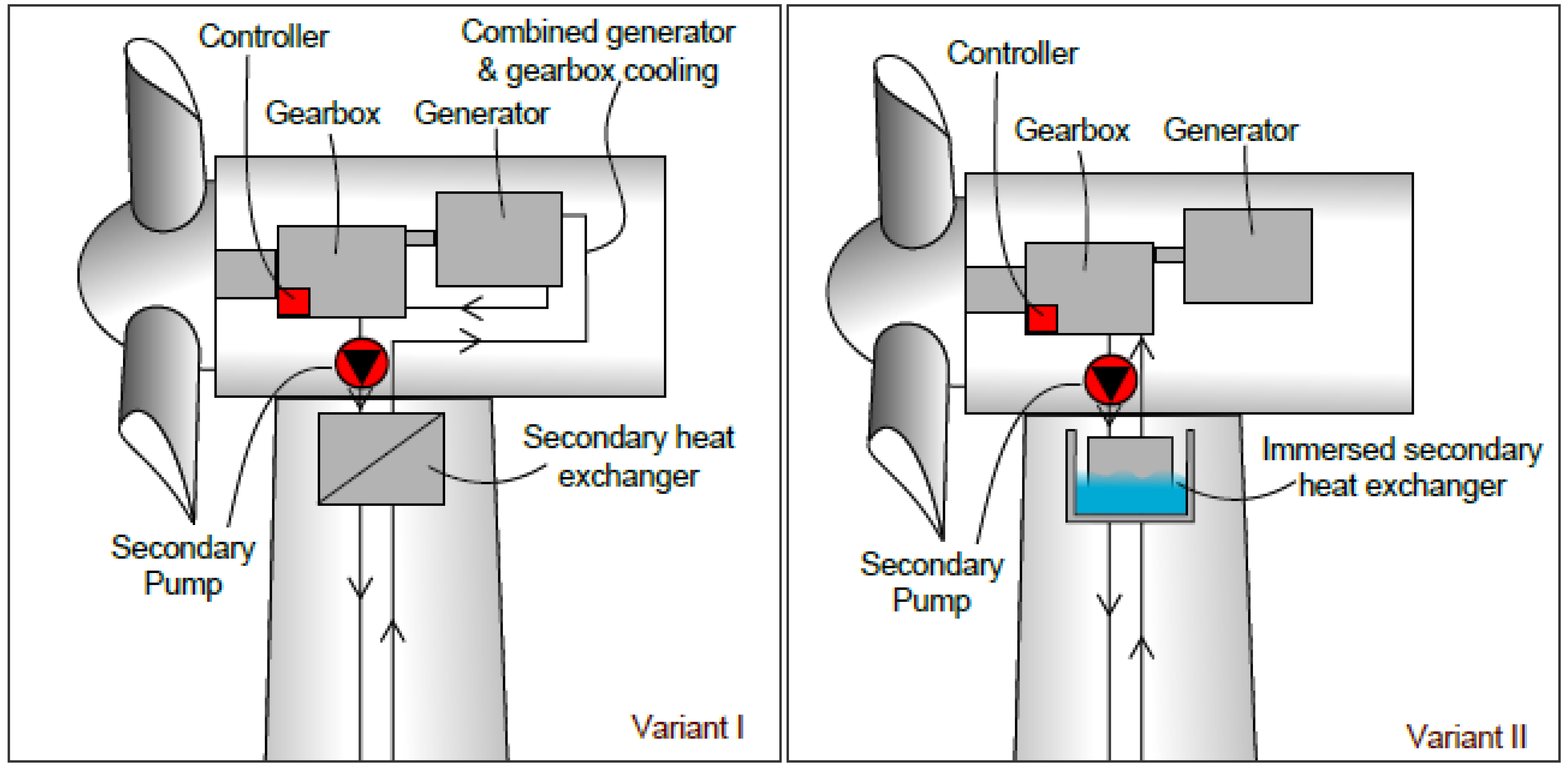
21]! It can be roughly estimated that a 3MW generator produces max 250 kW of waste heat. A new solution for wind turbine geo-cooling system heat transfer model is proposed consisting of full liquid cooling for all components, driving the heat to a centralized location at tower bottom. Then, a combination of liquid and geothermal cooling manages the dissipation of the excess heat in an efficient way to the environment. It is expected different operational modules of the internal cooling system to be studied in order to improve systems efficiency and extract heat as much as possible (
Figure 3).
Figure 3.
Various operational modules of the internal cooling system [
2,
17].
Figure 3.
Various operational modules of the internal cooling system [
2,
17].
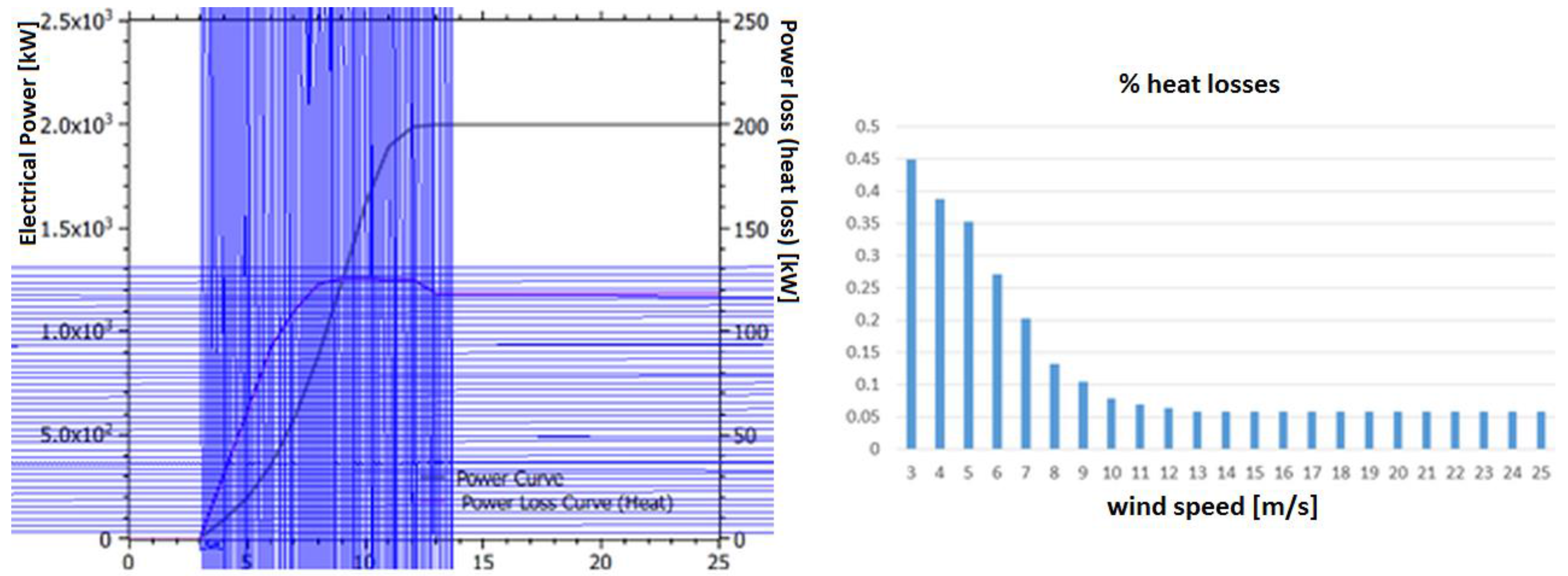
Based on the data provided from [
1] and based on the graphical solution developed, the heat losses were calculated for every 1 m/s step for a modern 2.0 MW wind turbine (
Figure 4). The percentage of the heat losses per step is included in the same figure.
Figure 4.
Graphical solution for the heat losses from a 2.0 MW wind turbine and heat losses percentage in relation to the wind speed (m/s) [
1].
Figure 4.
Graphical solution for the heat losses from a 2.0 MW wind turbine and heat losses percentage in relation to the wind speed (m/s) [
1].
It can be seen that the higher the wind speed the greater the energy losses (up to 11 m/s), however, at the same time, the smaller the heat loss percentage compared to the energy generated is (
Figure 4 and
Figure 5).
Figure 5.
Heat losses from a common 2.0 MW wind turbine related to the wind speed (m/s) [
1].
Figure 5.
Heat losses from a common 2.0 MW wind turbine related to the wind speed (m/s) [
1].
The consequences of low /medium wind speeds (4–11 m/s) were studied in more detail than the speeds greater than 11 m/s, since as seen from the diagrams heat losses remain steady. Above 12 m/s it is clear that the overall heat losses settled at approximately at 120 kW for a common 2.0 MW wind turbine.
The authors have considered the case study of a Greek island (Ikaria Island) from which data were used. Annual hourly measurements of wind speed, atmospheric pressure and temperature were used to train the Artificial Neural Network (ANN) for offering a 12-hour prediction. The ANN analysis tool from the Zaitun Time series was used for this purpose. The Hyperbolic Tangent and the Bipolar Sigmoid Functions were used—based on the trained network—to simulate the next 12 hours (
Figure 6). Based on the results the operator can estimate the forecasted amount of wasted heat and bid more accurately, minimizing the error, in the day-ahead market for the following hours.
Figure 6.
Wind Speed Forecasting results for the day-ahead market.
Figure 6.
Wind Speed Forecasting results for the day-ahead market.
Figure 7 presents a scatter plot between actual and predicted values stressing the difference between the hyperbolic tangent and the bipolar sigmoid functions.
The methodology that was followed, showed that based on the operation of the WT, there will be a significant amount of heat losses although based on the forecasting results, the WT will not be operating at full power.
Table 1 shows the power generated and the heat losses in (kW).
Figure 7.
A scatter plot between actual and predicted values.
Figure 7.
A scatter plot between actual and predicted values.
Table 1.
Heat losses calculated based on the graphical solution.
Table 1.
Heat losses calculated based on the graphical solution.
| Wind (m/s) | Power (kW) | Heat Losses (kW) | Heat Losses (%) |
|---|
| 3 | 10 | 4.5 | 45.0 |
| 4 | 85 | 33 | 38.8 |
| 5 | 170 | 60 | 35.3 |
| 6 | 350 | 95 | 27.1 |
| 7 | 550 | 112 | 20.4 |
| 8 | 900 | 120 | 13.3 |
| 9 | 1200 | 125 | 10.4 |
| 10 | 1575 | 125 | 7.9 |
| 11 | 1800 | 125 | 6.9 |
| 12 | 1950 | 125 | 6.4 |
| 13 | 2000 | 118 | 5.9 |
| 14 | 2000 | 118 | 5.9 |
| 15 | 2000 | 118 | 5.9 |
| 16 | 2000 | 118 | 5.9 |
| 17 | 2000 | 118 | 5.9 |
| 18 | 2000 | 118 | 5.9 |
| 19 | 2000 | 118 | 5.9 |
| 20 | 2000 | 118 | 5.9 |
| 21 | 2000 | 118 | 5.9 |
| 22 | 2000 | 118 | 5.9 |
| 23 | 2000 | 118 | 5.9 |
| 24 | 2000 | 118 | 5.9 |
| 25 | 2000 | 118 | 5.9 |
Table 2.
Heat losses calculated for the day-ahead market (next 12 h).
Table 2.
Heat losses calculated for the day-ahead market (next 12 h).
| H—ahead | Wind Speed Forecast (Hyperbolic Tangent) | Heat Losses (kW) | Wind Speed Forecast (Bipolar Sigmoid) | Heat Losses (kW) |
|---|
| 1 | 9.6763 | 120.1 | 9.6945 | 120.1 |
| 2 | 9.2276 | 123.6 | 9.3731 | 122.2 |
| 3 | 9.0385 | 125.0 | 9.0824 | 124.3 |
| 4 | 9.3185 | 122.9 | 8.9590 | 125.0 |
| 5 | 9.4921 | 121.5 | 8.8073 | 124.0 |
| 6 | 9.4101 | 122.2 | 8.5948 | 123.0 |
| 7 | 9.3081 | 122.9 | 8.3903 | 122.0 |
| 8 | 9.4400 | 122.2 | 8.2779 | 121.5 |
| 9 | 9.4742 | 121.5 | 8.1076 | 120.5 |
| 10 | 9.4501 | 121.5 | 7.9373 | 116.2 |
| 11 | 9.3871 | 122.2 | 7.7981 | 115.4 |
| 12 | 9.4345 | 122.2 | 7.7168 | 114.6 |
| SUM | | 1467.8 | | 1448.8 |
Based on that, and the results for the next 12 hours (using simple linear interpolation for the different wind speeds) it is estimated that the cumulative difference in heat losses between the two different methodologies followed is insignificant (
Table 2).


