Abstract
The static and dynamic performances of a machine tool structure are considered to constitute the primary factors affecting the load-carrying capacity, geometric accuracy and surface precision of the workpiece. The machining performance of a large machine tool under stable conditions is effectively determined by its dynamic response to the cutting force at low-frequency excitation. This study, therefore, investigated the static and dynamic characteristics of a large heavy-duty lathe machine tool in which the headstock and tailstock comprised critical component modules supporting a large workpiece during low-speed machining. Using a finite element model, the influences of the structural modules on the static and dynamic characteristics of the lathe were analyzed, considering the effects of the workpiece load. The results indicated that the fundamental vibration modes of the lathe were primarily dominated by headstock, tailstock, and workpiece behaviors. The maximum compliances of the lathe under the rated load were found to occur at relatively low frequencies (22, 40.7, and 82.7 Hz) and increase with the reduction in workpiece weight. Notably, these modal frequencies were significantly higher than the maximum rotational speed of the spindle (450 rpm). In addition, the dynamic rigidity corresponding to the rated speed was higher than that induced at the natural frequency. These results indicate that the subject lathe possesses sufficient capacity to sustain the cutting load during stable turning machining. This study can, therefore, help designers improve the performance of machine tools for future fabrication.
1. Introduction
In recent years, renewable energy power stations and offshore platforms have been vigorously developed, the demand for offshore wind turbines has increased considerably, and the capacity requirements for wind turbines have grown [1]. In response to this trend, wind turbines are being designed in progressively larger sizes. However, this has increased the demand for large structural components such as towers and rotor shafts, as well as heavy lifting equipment, prompting the development of heavy-duty multitasking turning machines in the manufacturing industry [2,3]. These heavy-duty machines can hold workpieces as long as 10 m, weighing more than 40 tons [4]. Meeting the requirements for processing quality, accuracy, and efficiency is an important task in the design of such heavy-duty machine tools [1].
The static structural performance of a machine tool affects its load-carrying capacity and the geometric accuracy of the machined workpiece. The dynamic characteristics of the tool have a significant influence on its motion precision and stability, processing quality, and machining efficiency. Machining performance can be expressed in terms of the material removal rate achieved while maintaining sufficiently high surface accuracy and can be optimized by selecting chatter-free machining conditions for a specific tool [5,6] based on the stability lobe diagram. According to machining mechanics, stability lobes can be calculated using the frequency response function (FRF) assessed at the tool point undercutting force excitation [7]. Essentially, the FRF of the tooling point can be considered representative of the dynamic characteristics of the machine structure and tooling module, which include the spindle tool with machine frame, workpiece and fixtures, lathe spindle chuck, and tailstock. Therefore, the machining stability and performance of a machine tool can be easily evaluated by measuring the frequency response of the tool point. For example, to identify the machine design features limiting productivity, Urbikain et al. [8] proposed a multimode analytical method for predicting the stability of a large horizontal lathe at a low rotational speed. Furthermore, Hung et al. [9] reported that the machining stability of a tool could be categorized into different ranges according to the FRF at the tool point, which clearly exhibited lower- and higher-frequency modes dominated by the dynamic behaviors of the machine structure and spindle tool, respectively.
However, heavy-duty machine tools are often designed using specifications defined to meet custom requirements for specific parts and operating conditions [1]. To conduct performance evaluations during the design stage, the structural characteristics of the machine can be characterized by static and dynamic behaviors under various loading modes, respectively, thereby enabling further optimization [10,11,12,13,14,15]. Hong et al. [10] conducted the static structural analysis of a five-axis turning–milling machine by using the computer aided engineering (CAE) commercial software simulation module. The static stresses and displacements of machine structure modules, such as primary and secondary shaft systems under different load modes and clamp boundary conditions of machinery beds were studied. With the same method, the natural frequencies of the machine with different clamping conditions were examined, which can provide a reference for the machine in safety conditions to avoid resonance [11]. Wang et al. [12] employed finite element modeling to analyze the dynamic performance of a precision machine tool and proposed structural optimization schemes for the machine bed accordingly. Hung et al. [13] investigated the dynamic characteristics of a milling machine with different headstocks using the finite element method and acceptance coupling analysis; their results indicated that a milling machine with a reformed headstock exhibited superior dynamic behavior compared to the original design, with a 10% improvement in dynamic stiffness. Chen et al. [14] compared the static and dynamic characteristics of a machine tool structure composed of different materials using a finite element modeling approach to show that the dynamic rigidities associated with granite machines were 50–100% larger than those associated with conventional casting machines. Recently, Ahmad et al. [15] applied the finite element method to investigate the dynamic characteristics of machine tool beds constructed using different polymer concrete materials in terms of their natural frequencies and dynamic stiffness. In order to enhance the damping capacity and rigidity, Chinnuraj et al. [16] proposed the design of a machine tool composed of a steel-reinforced polymer concrete structure. The structure rigidity and dynamic characteristics of different geometry designs were analyzed and compared by finite element analysis, which finally showed that dynamic characteristics were enhanced by 4–10% with improved stiffness and a mass reduction of 22%. Venugopal et al. [17] optimized the structural performance of the vertical machining center column by introducing various designs of steel reinforcement in the epoxy granite structure. Based on finite element analysis, the static stiffness and natural frequencies of the steel-reinforced epoxy granite column were proven to have about a 12–20% increment, higher than the cast iron structure. In addition, machining stability was enhanced and achieved by appropriately tuning the dynamic properties of the machine tool by using structure material with high damping properties. Dunaj et al. [18] developed a vertical lathe structure with a steel-polymer concrete composite, which was verified to show a significant increase in the damping ability by 239% with a reduction in the amplitude of dominant resonance by 81%. In a further application of steel-polymer concrete composite, the static stiffness of the vertical lathe machine was significantly increased by 30% [19].
For a large or heavy-duty machine tool, the primary modes dominating machining chatter often originate from low-frequency vibration [9], which is normally associated with the machine frame or primary modules, such as the spindle headstock, rather than the spindle tool or tool holder systems, which exhibit high-frequency vibration characteristics [20,21]. Based on this concept, the effects of the spindle assembly and headstock design on the dynamic characteristics of FRFs have been evaluated at different frequency ranges [12,22]. Dounar et al. [23] proposed strategies for enhancing the dynamic rigidity of a heavy precision lathe by analyzing the FRFs at the spindle headstock and tailstock using finite element analyses; the results demonstrated that the rigidities of the reinforced headstock and tailstock were appropriately increased compared to the original design.
In this study, a huge multi-axis milling turning machine was designed for the manufacturing of the large components used in the offshore wind power industry. The design issue was focused on the load-carrying capacity, structure rigidity against the bending deformation of the workpiece and the vibration response characteristics during low-speed cutting. According to a study [24], the machine–tool–workpiece deformation caused by cutting force in turning is one of the main errors affecting the machining precision. In addition, currently, the finite element modeling approach is considered an effective tool for modeling machine tools as it can accurately predict the dynamic behavior of prototype designs without requiring physical fabrication. Therefore, in this study, the finite element method was employed to analyze the static and dynamic characteristics under the rated loading. These characteristics were quantified in terms of the rigidities in static and dynamic loading conditions, respectively. The effects of the structural modules on the dynamic characteristics of the lathe were then evaluated. The results can help designers realize the design strategies for enhancing the performance of machine tools in specific fabrication scenarios.
2. Finite Element Modeling Approach
2.1. Description of Lathe Machinery
Figure 1 shows a geometrical model of the five-axis turning-milling lathe, which primarily comprises a machine bed, spindle headstock with chuck, tailstock, horizontal milling module, and turning saddle with a carriage feeding mechanism. The specifications of this machine are listed in Table 1. To enhance the rigidity of the spindle, the rotating shaft was supported by front bearings, rear bearings, and supporting bearings in the housing; these were, respectively, configured as follows: (1) two single-row tapered roller bearings in a “back-to-back” (DB) arrangement (LM451349), (2) two-row tapered roller bearings (LM45345), and (3) a deep groove ball bearing (61,952 MA). The tool carriage with the saddle and milling module was driven to feed along the Z-direction on the sliding guideway by a gear train with a rack and pinion and to feed along the X-direction by linear guides. The sliding guideway was coated with a 1.5 mm thick antifriction liner (Turcite-B) that provided sufficient rigidity and damping ability to support the moving components on the machine bed.
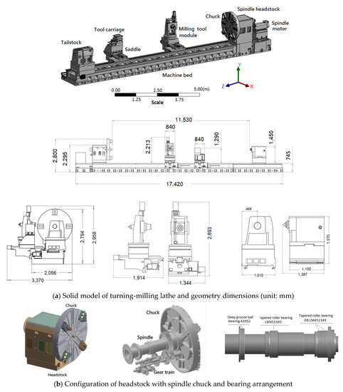
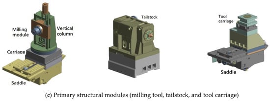
Figure 1.
Solid model of the five-axis turning-milling lathe and its primary structure modules (headstock with spindle chuck, milling tool, tool carriage, and tailstock).

Table 1.
Specifications of the turning-milling lathe.
2.2. Finite Element Model
In this study, the dominance of the primary machine modules in the structural performance of the lathe was the focus of concern. The finite element method was, therefore, employed to analyze the static and dynamic behaviors of the machine models under the rated loading. To construct the finite element model, a geometrical solid model was appropriately simplified by removing or neglecting small holes, fillets, rounds, minor parts, and trivial features. Figure 2 shows the simplified solid lathe model, and the finite element model is shown in Figure 3. The structural components were meshed using eight-node hexahedral and ten-node tetrahedral elements for a total of 814,395 elements and 1,565,731 nodes. The contact surfaces between the machine bed or guideways and the primary modules, such as the headstock, tailstock, and support rollers were assumed to be in a fully bonded state. The ball screws in the feeding mechanism of the tool carriage and saddle in the X- and Z-directions were appropriately simplified as cylindrical bodies with equivalent diameters by neglecting the rolling elements. The contact surfaces between the screw shaft and ball nut were assumed to be fully bonded. The bearings in the headstock spindle were considered to be a critical factor affecting the high-frequency dynamic behavior of the machine. The rolling interfaces between the rolling elements and raceways were simulated as surface-to-surface contact elements with adequate contact stiffness, following the method presented in [25], as shown in Figure 4. The contact stiffness was derived based on Hertzian theory [26], which describes the relationship between the contact force and local deformation at the contact point as follows:
where δ is the elastic deformation at the contact point, Q is the contact force, and Kh is the Hertz constant, determined by the geometric and material properties of the contacting components [27]. The contact stiffness Kn at the contact point can then be obtained using the following equation:
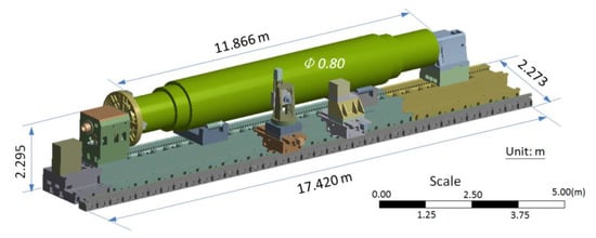
Figure 2.
Simplified model of the entire turning-milling lathe with workpiece in length of 11.866 m and diameter of 0.8 m.
Figure 3.
Finite element model of lathe machine without (top) and with (bottom) a workpiece.
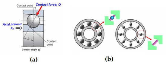
Figure 4.
Modeling of the bearings in the spindle, (a) Schematic of angular contact bearing, (b) Modelling of the contact interface in bearing [25].
For a roller bearing, the contact force Q is related to the local deformation δ at the contact point between the roller and raceway as per the following equation [28]:
where Eeq is the relative elastic stiffness between the contacting bodies and L is the roller length. Thus, the normal stiffness Kn is given as
For practical applications relying on simplified contact geometries, Palmgren [28] used the following empirical equation to describe the linear contact elastic deformation between a cylindrical body and a flat surface:
Based on the spindle bearing specifications, the normal stiffness at each contact point on the interface between the rolling element and raceway was calculated to be 1610 N/μm and 105 N/μm for the roller and ball bearings, respectively. The overall contact stiffness of each bearing was distributed among spring elements circumferentially surrounding the inner and outer raceways in the model. The primary machine modules were modeled using gray cast iron with a density ρ = 7280 kg/m3, Young’s modulus E = 130 GPa, and Poisson’s ratio μ = 0.3. Other components, such as the ball bearings, spindle unit, and gear train in the headstock, ball screw, and tailstock were modeled using a steel alloy with a density ρ = 7860 kg/m3, Young’s modulus E = 200 GPa, and Poisson’s ratio μ = 0.3. The boundary conditions on the bottom surface of the machine model were assumed to be fully constrained.
2.3. Analysis Cases
The structural performance of the entire lathe structure comprising the primary modules was investigated through static and dynamic analyses of the finite element model. The static analysis evaluated the deformation of the entire machine structure and its rigidity against the rated load. Dynamic analyses, including modal and harmonic analyses, were conducted to determine the dominance of the primary structures in the dynamic behavior of the entire machine structure under cyclic excitation owing to an external load.
2.3.1. Static Analysis
In this analysis, the maximum loads acting on the lathe were evaluated for a workpiece weighing 60 tons, clamped to the spindle chuck, and simply supported by the tailstock center, as shown in Figure 3. The deformation behavior of the machine structure and the reaction forces at the supports of the workpiece under the rated load were then calculated and the static rigidities of the machine structure were obtained at the different supports.
2.3.2. Modal Analysis
The natural vibration characteristics of the entire lathe structure were analyzed using modal analysis. The effects of the workpiece on the modal characteristics of the machine, such as its natural frequency and vibration shape, were evaluated, elucidating the rigidities of the structure modules in different directions.
2.3.3. Harmonic Analysis
A series of harmonic analyses was conducted to simulate the dynamic response of the spindle headstock and tailstock when subjected to the force applied at the chuck and center apex, respectively. As shown in Figure 5, this analysis applied a unit force to the chuck in the lateral and vertical directions at frequencies ranging from 0 to 300 Hz. Similarly, a harmonic analysis was performed for the tailstock by applying a unit force to the spindle center in the lateral and vertical directions at frequencies ranging from 0 to 300 Hz. When conducting the harmonic analyses using finite element modeling, a constant damping ratio of 2.5% was assumed for the machine structure as it was made of cast iron material [29]. The results of these analyses reveal the vibration modes dominating the dynamic behavior of the lathe during machining; hence, the dynamic compliance or dynamic rigidity of the machining system can be assessed to propose a strategy for improving its performance.
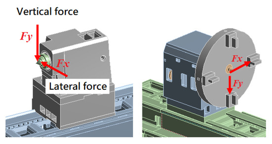
Figure 5.
Schematic of the harmonic force acting on the tailstock and the spindle chuck in the lateral and vertical directions.
2.3.4. Effects of Workpiece Load
Simulations were conducted to model the frequency response of the entire machine when carrying a cylindrical workpiece of various weights under an exciting force. The unit cutting force applied to the workpiece was decomposed into three components: the cutting direction (Fc), feeding direction (Ff), and radial direction (Fr) forces, as shown in Figure 6. The component ratios of Fc, Ff, Fr were assigned mean values of 0.68, 0.62, and 0.37, respectively, based on a previous study [30]. The effects of the workpiece weight on the dynamic behaviors of the entire lathe, including the headstock, tailstock, and workpiece itself, were then examined under the execution of the cutting force at different frequencies. Three workpiece weights were evaluated: 60 tons (full rated load), 27 tons (45% of the full rated load), and 15 tons (25% of the full rated load).
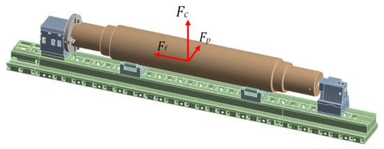
Figure 6.
Schematic of the cutting force acting on the workpiece, which was decomposed into components in the cutting direction (Fc), feeding direction (Ff) and radial direction (Fr).
3. Results and Discussions
3.1. Static Stiffness
Figure 7 shows the total deformation of the entire machine under its self-weight and the rated load of the workpiece (60 tons). The maximum deflection of the workpiece was 64.7 μm near the middle section owing to bending under gravitational load. The total deformation of the machine bed at the roller supports was approximately 23.8–27.2 μm and the deflection at the spindle chuck and apex of the tailstock were approximately 25 and 22 μm, respectively. Notably, the spindle chuck mounted on the headstock exhibited significant deflection owing to the clamping load from the workpiece.
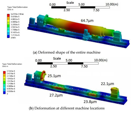
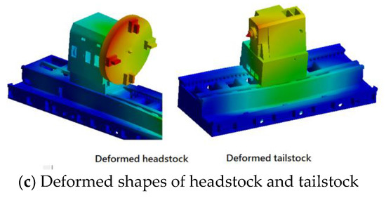
Figure 7.
Deformation of the machine structure under rated workpiece load of 60 tons.
Using the static analysis results, the reaction forces at the workpiece supports were calculated as presented in Table 2, in which the rigidities (Ks) of the machine structure were determined at different locations based on Ks = Rn/δ, where Rn is the reaction of the considered support against the loads and δ is the deflection at that support. The results shown in Table 2 indicate that under the rated load, the rigidity was lowest at the headstock chuck and tailstock center. The rigidities of these modules can be enhanced by adding stiffeners to their weakest parts.
Table 2.
Comparison of the static characteristics of primary machine modules under the rated load.
3.2. Vibration Mode Characteristics
Figure 8 shows the fundamental vibration modes of the spindle headstock. The first mode comprised the lateral bending vibration of the headstock accompanied by the swinging motion of the chuck about the Z-axis at 67 Hz; the second mode comprised the bending vibration of the headstock accompanied by the nodding motion of the chuck about the X-axis at 78 Hz; the third mode comprised the torsion vibration of the chuck about the Z-axis at 86 Hz, and the fourth mode comprised the larger bending motion of the headstock with the chuck about the Y-axis at a frequency of 99 Hz. Clearly, the vibration motions of the headstock can be classified among the lower-frequency modes, which were considered to be the primary characteristic dominating the dynamic performance of large heavy-duty machine tools. These vibration modes originate directly from the natural vibration behavior of the headstock with the spindle chuck, while the vibration frequency is determined by the structural rigidity of the headstock. This rigidity can be attributed to the connection state between the headstock and machine bed, the mounting condition of the chuck in the spindle nose, and the stiffness of the spindle shaft. The higher-frequency modes shown in Figure 8e,f were found to occur at 120 Hz and were primarily induced by the bending vibration of the spindle shaft in the lateral and vertical directions, accompanied by deformation of the chuck. Note, that for these modes, the presence of the heavyweight chuck (approximately 1700 kg) significantly shifted the frequency to a lower value compared with the headstock spindle without the chuck (1307 Hz).
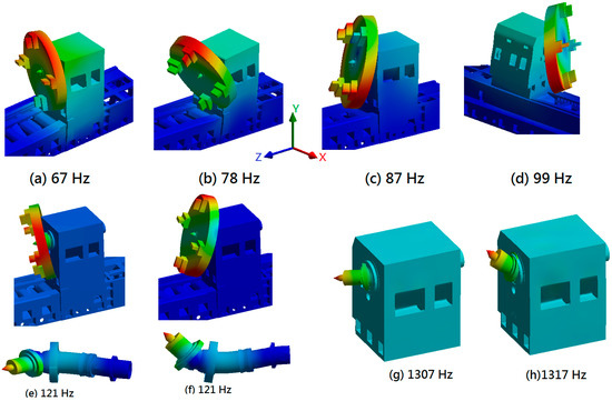
Figure 8.
Fundamental vibration modes of the headstock with chuck, including the lower- and higher-frequency modes associated with the bending motion of spindle shaft with and without the chuck.
This analysis model demonstrated that the headstock exhibited different rigidities in different vibration motions. The rigidity against the rolling motion was lower than that against the nodding motion. In addition, when the fundamental vibration was induced, it caused the headstock chuck to deviate from the neutral axis, which will affect the clamping stability of the workpiece during machining.
Figure 9 illustrates the fundamental vibration modes of the tailstock. The first mode comprised the lateral bending vibration or rolling motion of the tailstock about the Z-axis at 78 Hz, the second mode comprised the bending vibration or pitching motion of the tailstock about the X-axis at 109 Hz, the third mode comprised the upward motion of the tailstock along the Y-axis at 208 Hz, and the fourth mode comprised the twisting vibration or yawing motion of the tailstock about the Y-axis at a higher frequency of 245 Hz. Clearly, the machine base deformed along with the vibration of the tailstock when these modes occurred; this deformation is dependent on the rigidity of the connection between the tailstock and guideway of the machine base. Similar to the headstock, the lower-frequency modal characteristics of the tailstock can be attributed to the structural rigidity of the module, which is determined by the geometric configuration and fixation on the guideway of the machine bed. Indeed, this analysis reveals that the tailstock also exhibited a lower rigidity against rolling motion than against pitching motion.
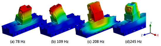
Figure 9.
Fundamental vibration modes of the headstock with the chuck.
Figure 10a–e shows that the vibration modes of the entire lathe structure with a workpiece rated at a weight of 60 tons were in the lower-frequency range of 21.5–82.7 Hz. These modes were primarily associated with the vibration motion of the workpiece supported between the headstock chuck and tailstock center. A local coordinate system defined as x, y, and z was established on the workpiece to illustrate this vibration motion. The first mode at 21.5 Hz comprised the rolling motion of the workpiece about the local coordinate z-axis, as shown in the figure, with the headstock and tailstock exhibiting lateral bending vibration with the rolling of the workpiece, as shown in Figure 8a and Figure 9a. The second mode at 32.8 Hz comprised the pitching motion of the workpiece about the x-axis, with the headstock and tailstock exhibiting forward and backward bending vibrations, as shown in Figure 8b and Figure 9b. The third mode at 40.7 Hz comprised the vertical motion of the workpiece along the y-axis, the fourth mode at 45.6 Hz comprised the twisting or yawing motion of the workpiece about the y-axis, and the fifth mode at 82.7 Hz comprised the larger pitch motion of workpiece about the x-axis, but it was also accompanied by the nodding motion of the headstock chuck (Figure 8b) and the twisting vibration of the tailstock (Figure 9d). The vibration mode shapes indicate that these fundamental modes were governed not only by the workpiece but also by the vibration characteristics of the headstock chuck and tailstock. In other words, the weight and geometry of the workpiece as well as the structural rigidity of the headstock and tailstock all exert significant influences on the vibration characteristics of the entire machine. However, note that for the first two modes, the critical speed of the machine was approximately 1300 rpm—much higher than the maximum rotational speed of the spindle, which was rated at 450 rpm. This represents a favorable condition for the prevention of vibration resonance during machining [31].
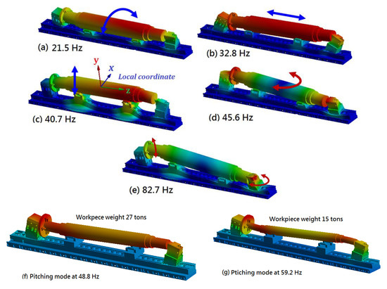
Figure 10.
Fundamental vibration modes of the entire lathe machine with a workpiece.
The influence of the workpiece weight on the vibration characteristics was then examined based on the results of the modal analysis, with the results shown in Figure 10f,g and Table 3. The modal frequencies associated with the fundamental modes varied with the weight of the workpiece. For example, the vibration frequency of the rolling motion of the workpiece about the z-axis increased from 21.5 Hz to 35.4 Hz with a 75% decrease in the weight of the workpiece.
Table 3.
Modal frequencies of the lathe machine according to workpiece weight.
3.3. Dynamic Characteristics—FRFs
3.3.1. Spindle Chuck and Tailstock
Figure 11 illustrates FRFs predicted at the spindle chuck under a force applied in the lateral (X-axis) and vertical (Y-axis) directions. An FRF is expressed in terms of the vibration amplitude or compliance magnitude as a function of frequency. As can be observed from the X-direction FRF in the figure, a significant amplitude near ~67 Hz was associated with the first natural mode of the headstock, and the next near ~87 Hz corresponded to the second mode. Similarly, for the Y-direction FRF, the largest vibration peak occurred in the third mode (78 Hz), followed by the fourth mode (98 Hz) owing to the forward nodding vibration of the headstock with the spindle chuck. These lower-frequency responses were dominated by the structural rigidity of the headstock bolted to the machine bed. Based on the predicted FRFs, the minimum dynamic compliance of the spindle chuck in the lateral and vertical directions was calculated to be approximately 0.0131 and 0.00923 μm/N, respectively, corresponding to dynamic stiffness of 76.8 and 110.0 N/μm. This confirms that the dynamic stiffness of the spindle chuck was 54% larger in the vertical direction than in the lateral direction, as was found in the modal analysis, demonstrating that the frequency of the second mode in forward nodding vibration was larger than that of the first mode in lateral bending vibration. These characteristics are favorable for enabling the spindle chuck to sustain the dynamic loading induced by a heavy workpiece during machining. Furthermore, note that for the FRF in the vertical direction, the dynamic stiffness at zero frequency was approximately 1150 N/m, which is equivalent to the static stiffness under the rated workpiece load (1102 N/m), as presented in Section 3.2.
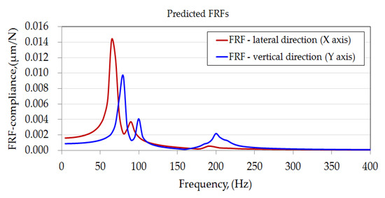
Figure 11.
Predicted FRFs for the spindle chuck.
Figure 12 illustrates the dynamic responses of the tailstock in the lateral and vertical directions when subjected to lower-frequency excitation. Similar to the spindle chuck, the tailstock exhibited lower-frequency responses under cyclic excitation. The first and second natural modes associated with the lateral bending and forward nodding motion dominated the dynamic behaviors of the tailstock in the lateral and vertical directions, respectively. Based on the predicted FRFs, the maximum dynamic compliance of the tailstock in the lateral and vertical directions was calculated to be approximately 0.0120 and 0.0072 μm/N, respectively. The dynamic stiffness in the vertical direction was about 138.8 N/μm, which is significantly higher than that in the lateral direction (83.3 N/μm).
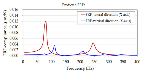
Figure 12.
Predicted FRFs for the tailstock.
3.3.2. Effects of Workpiece Weight
- (a)
- FRFs of the workpiece
Figure 13 illustrates the FRFs predicted at the cutting point on the workpiece in three orthogonal directions. These FRFs represent the variation in dynamic compliance with the change in the excitation frequency of the cutting force and show that the frequency responses of the workpiece vary with its weight. The maximum compliance occurs at a different frequency for each orthogonal direction; these frequencies are associated with the vibration modes for rolling motion in the X-direction, vertical motion in the Y-direction, and pitching modes in the Z-direction.
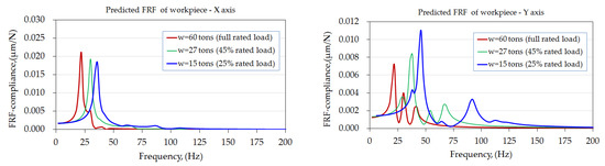
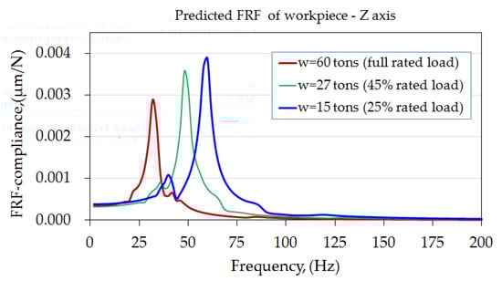
Figure 13.
Predicted FRFs of the workpiece in the three orthogonal directions under force excitation.
In addition, as the workpiece weight decreased, the maximum compliance in the X-direction decreased and that in the Y- and Z-directions increased. The results indicate that the workpiece had a higher rigidity in the longitudinal direction, for which it exhibited a compliance of less than 0.004 μm/N than in the lateral and vertical directions, for which the compliances were approximately 0.0183–0.0211 μm/N and 0.0075–0.011 μm/N, respectively.
- (b)
- FRFs of the headstock and tailstock
Figure 14 depicts the frequency responses predicted at the spindle headstock, demonstrating the impact of workpiece weight on the vibration behaviors of the headstock under cutting force excitation. The maximum compliance of the headstock chuck and the excitation frequency was significantly affected by the workpiece weight. For comparison, the dynamic rigidities corresponding to the maximum compliance of the headstock are presented in Table 4. It can be observed that the rigidity in X-directions is around 107–148 N/μm, higher than in Y and Z directions, around 287–721 N/μm. Besides, rigidities in the X- and Z-directions were affected to increase and decrease, respectively, as the workpiece weight decreased. However, variation in workpiece weight has no apparent influence on the rigidities in Y-direction.
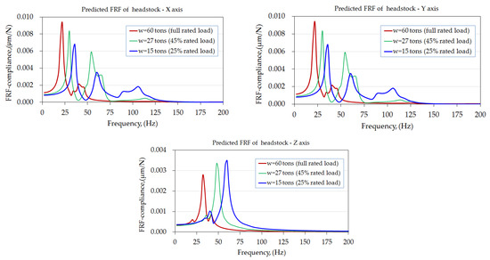
Figure 14.
Predicted FRFs of headstock in the three orthogonal directions under force excitation.
Table 4.
Minimum dynamic rigidity of headstock under different loading.
Figure 15 illustrates the frequency responses predicted at the center of the tailstock. The depicted vibration behaviors are similar to those of the headstock, which were mainly dominated by the rolling, vertical, and pitching motions of the entire machine with the loading effects of the workpiece. Clearly, the workpiece weight had a significant influence on the compliance of the tailstock center. Indeed, as shown in Table 5, rigidity in X-directions is around 46–80 N/μm, which is higher than in Y and Z directions, around 131–376 N/μm. In addition, rigidities in the X- and Z-directions were affected to increase and decrease, respectively, as the workpiece weight decreased. However, the rigidity in the Y-direction exhibited no apparent tendency to change with the variation in workpiece weight.
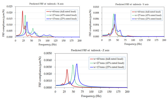
Figure 15.
Predicted FRFs of the tailstock in the three orthogonal directions under force excitation.
Table 5.
Minimum dynamic rigidities of the tailstock under different loading.
Summarizing the analysis results presented in Table 4 and Table 5, we observe that the two primary structural modules exhibited similar vibration characteristics under forced excitation, but their dynamic rigidities in the orthogonal directions were quite different. Indeed, the smallest rigidities occurred in the lateral direction and increased from 107 to 148 N/μm for the headstock and from 46 to 80 N/μm for the tailstock when the workpiece weight decreased from 60 to 15 tons. Additionally, the minimum dynamic rigidity of the workpiece increased from 47 to 54 N/μm. For the machine with a workpiece at the full rated load of 60 tons, the headstock, tailstock and workpiece exhibited their smallest rigidities of approximately 107, 46 and 47 N/μm, respectively, occurring in the lateral direction (along the X-axis) at a resonant frequency of 22 Hz. Notably, these dynamic rigidities were higher than the dynamic rigidity threshold (20 N/μm) required for a stable cutting process [24]. However, according to machining mechanics, machining stability is determined by the real part of the FRFs. Therefore, the variation in compliance associated with the change in the frequency response under force excitation may affect the machining stability of the turning process. For the workpiece, the maximum compliance in the vertical direction increased by 45% when its weight decreased from 60 to 15 tons. The results provide a reference for evaluating the capability for stable machining of larger workpieces. In addition, the rigidity of the workpiece was generally highest in the longitudinal direction, while that in the vertical direction was superior to that in the lateral direction. The current results thereby clearly indicate that the spindle chuck and tailstock represent critical modules affecting the vibration behavior of the workpiece when the cutting force is exerted during the turning process. A similar investigation conducted in [21,32] also reported that the headstock and tailstock played critical roles in the dynamics of a large precise lathe and that the static and dynamic rigidities of the machine were determined by the geometric design of its structure to accommodate the maximum diameter of the workpiece.
For the lathe evaluated in this study, the target workpiece, which was 60 tons in weight and 1600 mm in diameter, was considered to be more rigid in the longitudinal direction. According to the modal analysis, the lower-frequency vibration modes primarily comprised the deformations of the headstock and tailstock. Therefore, the structural rigidity of the headstock with the spindle chuck and the supporting stiffness of the tailstock substantially influenced the dynamic compliance of the workpiece under machining. Choi et al. [33] investigated the structural characteristics of a heavy-duty lathe for machining large crankshafts and reported that the static stiffness of the headstock was 1141.9 and 1424.8 N/μm in the lateral and vertical directions, respectively, and the dynamic stiffness was 77.6 and 157.1 N/μm, respectively. In addition, the headstock was shown to exhibit the highest rigidity in the longitudinal direction, followed by the vertical direction, then the lateral direction. In this study, the static rigidity of the headstock under a rated load of 60 tons was estimated to be 1102 N/μm, and the minimum dynamic stiffness in the lateral and vertical directions was 107.16 and 595.69 N/μm, respectively. Comparing this study with Choi et al. [33], the two heavy lathe machines were clearly designed with different structural configurations and specifications; however, they exhibited similar structural characteristics. Indeed, the static stiffness of the machine evaluated in this study is comparable to that of the machine in the study by Choi et al., but its dynamic stiffness in the X- and Y-directions are higher than those presented in the study [33]. Overall, the dynamic characteristics of the large heavy-duty lathe evaluated in this study appear to have been effectively and reasonably analyzed when comparing the results with those in previous literature. The characteristics obtained in this study can, therefore, inform valuable design improvements for the machine structure, enable evaluation of loading capability, and help to ensure stable machining.
4. Conclusions
This study investigated the static and dynamic characteristics of a large heavy-duty lathe machine tool under rated workpiece loads using a finite element model. Its static rigidity was evaluated and its dynamic behavior was characterized in terms of the FRFs assessed for the workpiece and primary structural modules. Several conclusions can be drawn based on the results, as follows:
- The machine bed had a higher rigidity against workpiece loads, whereas the headstock and tailstock comprised the critical modules dominating the load capacity.
- The dynamic characteristics of the entire machine loaded with a workpiece subjected to a simulated cutting force were affected by the change in compliance and resonant frequency according to the workpiece weight.
- The lowest natural frequency of the lathe machine was approximately 22 Hz—significantly higher than the maximum rotational speed of the spindle, which was rated at 450 rpm. This is a favorable condition for the prevention of vibration resonance during machining.
- Finally, the structural stiffness of the headstock and tailstock substantially influenced the dynamic compliance of the workpiece under the machining force. The two modules exhibited superior rigidity in the longitudinal direction, and the rigidity in the vertical direction was higher than that in the lateral direction. In addition, the static and dynamic stiffness of the large heavy-duty lathe machine exhibited characteristics comparable to those presented in previous literature.
These findings clearly demonstrate the finite element model’s effectiveness in analyzing the structural performance of a large heavy-duty lathe, providing a valuable reference for informing machine structure design improvements and enabling the evaluation of its loading capability while ensuring stable machining. However, it was also noticed that this machine is suitable for low-speed operation, with machining vibration normally dominated by the machine structure and the modules. For other machines at higher speed machining, it will be mainly affected by the mechanical characteristics of the spindle module. Under this situation, the modeling of the spindle-bearing system and feeding mechanism along with the interface characteristics should be taken into consideration when developing the whole machine model.
Author Contributions
Conceptualization, C.-Y.L.; Y.-P.L. and J.-P.H.; methodology, C.-Y.L.; Y.-P.L. and J.-P.H.; software, C.-Y.L.; Y.-P.L.; B.-C.L. and J.-P.H.; validation, C.-Y.L.; W.-Z.L. and J.-P.H.; formal analysis, C.-Y.L.; B.-C.L. and W.-Z.L.; investigation, C.-Y.L.; W.-Z.L.; B.-C.L. and J.-P.H.; resources, C.-Y.L.; Y.-P.L. and J.-P.H.; data curation, C.-Y.L.; W.-Z.L.; B.-C.L. and J.-P.H.; writing—original draft preparation, C.-Y.L.; Y.-P.L.; writing—review and editing, Y.-P.L. and J.-P.H.; visualization, Y.-P.L. and J.-P.H.; supervision, J.-P.H.; project administration, Y.-P.L. and J.-P.H.; funding acquisition, J.-P.H. All authors have read and agreed to the published version of the manuscript.
Funding
This research received no external funding.
Institutional Review Board Statement
Not applicable.
Informed Consent Statement
Not applicable.
Data Availability Statement
Not applicable.
Acknowledgments
We gratefully acknowledge the support for this work provided by L&L Machinery Industry Co., Ltd., Taichung, 41154, Taiwan.
Conflicts of Interest
The authors declare no conflict of interest.
References
- Uriarte, L.; Zatarain, M.; Axinte, D.; Yagüe-Fabra, J.; Ihlenfeldt, S.; Eguia, J.; Olarra, A. Machine tools for large parts. CIRP Ann.-Manuf. Technol. 2013, 62, 731–750. [Google Scholar] [CrossRef]
- An, H.S.; Cho, Y.J.; Choi, Y.H.; Lee, D.W. Development of a multi-tasking machine tool for machining large scale marine engine crankshafts and its design technologies. J. Korean Soc. Precis. Eng. 2012, 29, 139–146. [Google Scholar] [CrossRef][Green Version]
- Jang, S.H.; Choi, Y.H.; Kim, S.T.; An, H.S.; Choi, H.B.; Hong, J.S. Development of core technologies of multi-tasking machine tools for machining highly precision large parts. J. Korean Soc. Precis. Eng. 2012, 29, 129–138. [Google Scholar] [CrossRef]
- Maschinenbau, W. Customized Machine Tools for Heavy-Duty Machining. Available online: https://www.sme.org/technologies/articles/2020/june. (accessed on 5 June 2022).
- Tekeli, A.; Budak, E. Maximization of chatter-free material removal rate in end milling using analytical methods. Mach. Sci. Technol. 2005, 9, 147–167. [Google Scholar] [CrossRef]
- Budak, E.; Tekeli, A. Maximizing chatter free material removal rate in milling through optimal selection of axial and radial depth of cut pairs. CIRP Ann.-Manuf. Technol. 2005, 54, 353–356. [Google Scholar] [CrossRef]
- Altintas, Y.; Budak, E. Analytical prediction of stability lobes in milling. CIRP Ann.-Manuf. Technol. 1995, 44, 357–362. [Google Scholar] [CrossRef]
- Urbikain, G.; Campa, F.J.; Zulaika, J.J.; De Lacalle, L.N.L.; Alonso, M.A.; Collado, V. Preventing chatter vibrations in heavy-duty turning operations in large horizontal lathes. J. Sound Vib. 2015, 340, 317–330. [Google Scholar] [CrossRef]
- Hung, J.P.; Lai, Y.L.; Lou, T.L. Analysis of the machining stability of a milling machine considering the effect of machine frame structure and spindle bearings: Experimental and finite element approaches. Int. J. Adv. Manuf. Technol. 2013, 8, 2393–2405. [Google Scholar] [CrossRef]
- Hong, C.C.; Chang, C.L.; Lin, C.Y. Static structural analysis of great five-axis turning–milling complex CNC machine. Eng. Sci. Technol. Int. J. 2016, 19, 1971–1984. [Google Scholar] [CrossRef]
- Hong, C.C. Dynamic structural analysis of great five-axis turning-milling complex CNC machine. Glob. J. Eng. Res. 2017, 17, 1–8. [Google Scholar]
- Wang, F.Q.; Rui, Z.Y.; Wu, Q. Structural dynamic analysis and optimization of precision NC machine tool bed based on the unit structure. Appl. Mech. Mater. 2011, 44, 200–205. [Google Scholar] [CrossRef]
- Hung, J.P.; Wu, K.D.; Lin, W.Z.; Shih, W.C. Analyzing the dynamic characteristics of milling tool using finite element method and receptance coupling method. Eng. Appl. Sci. Res. 2019, 9, 3918–3923. [Google Scholar] [CrossRef]
- Chen, T.C.; Chen, Y.J.; Hung, M.H.; Hung, J.P. Design analysis of machine tool structure with artificial granite material. Adv. Mech. Eng. 2016, 8, 1687814016656533. [Google Scholar] [CrossRef]
- Ahmad, S.F.; Jagadeesha, T. Dynamic characteristics analysis of kirloskar turn master35 machine tool bed with different polymer concrete materials. In Modeling, Simulation and Optimization; Springer: Singapore, 2022; pp. 329–338. [Google Scholar]
- Chinnuraj, S.; Thyla, P.R.; Elango, S.; Venugopal, P.R.; Mohanram, P.V.; Nataraj, M.; Ayyasamy, S. Static and dynamic behavior of steel-reinforced epoxy granite CNC lathe bed using finite element analysis. Proc. Inst. Mech. Eng. Pt. L J. Mater. Des. Appl. 2020, 234, 595–609. [Google Scholar] [CrossRef]
- Venugopal, P.R.; Kalayarasan, M.; Thyla, P.R.; Mohanram, P.V.; Nataraj, M.; Mohanraj, S.; Sonawane, H. Structural investigation of steel-reinforced epoxy granite machine tool column by finite element analysis. Proc. Inst. Mech. Eng. Pt. L J. Mater. Des. Appl. 2019, 233, 2267–2279. [Google Scholar] [CrossRef]
- Dunaj, P.; Powałka, B.; Berczyński, S.; Chodźko, M.; Okulik, T. Increasing lathe machining stability by using a composite steel–polymer concrete frame. CIRP J. Manuf. Sci. 2020, 31, 1–13. [Google Scholar] [CrossRef]
- Dunaj, P.; Dolata, M.; Tomaszewski, J.; Majda, P. Static stiffness design of vertical lathe with steel-polymer concrete frame. Int. J. Adv. Manuf. Technol. 2022, 121, 1149–1160. [Google Scholar] [CrossRef]
- Lai, Y.L.; Chen, Y.R.; Hung, J.P.; Luo, T.L.; Hsiao, H.H. Effect of the machine frame structures on the frequency responses of spindle tool. Int. J. Mech. Mechatron. Eng. 2012, 6, 1862–1867. [Google Scholar]
- Dounar, S.; Iakimovitch, A.; Jakubowski, A. Finite Element Method analysis of the deformation of the shaft and supports of a large, precise lathe–Cutting force excitation. Sci. J. Marit. Univ. Szczec. 2020, 62, 91–98. [Google Scholar]
- Zhang, Y.; Liu, C. Study on the dynamic performance of spindle assemble and headstock. In Proceedings of the 2010 IEEE International Conference on Mechatronics and Automation, Xi’an, China, 4–7 August 2010; pp. 1121–1126. [Google Scholar]
- Dounar, S.; Jakubowski, A. Dynamic Finite Element Analysis of Rotor-Shaft Fastening into a Heavy Precise Lathe. Sci. J. Marit. Univ. Szczec. 2021, 66, 37–45. [Google Scholar]
- Olvera, D.; de Lacalle, L.N.; Compeán, F.I.; Fz-Valdivielso, A.; Lamikiz, A.; Campa, F.J. Analysis of the tool tip radial stiffness of turn-milling centers. Int. J. Adv. Manuf. Technol. 2012, 60, 883–891. [Google Scholar] [CrossRef]
- Hung, J.P.; Lin, W.Z.; Chen, Y.J.; Luo, T.L. Investigation of the machining stability of a milling machine with hybrid guideway systems. Appl. Sci. 2016, 6, 76. [Google Scholar] [CrossRef]
- Brewe, D.E.; Hamrock, B.J. Simplified solution for elliptical-contact deformation between two elastic solid. J. Lubr. Technol. 1997, 99, 485–487. [Google Scholar] [CrossRef]
- Lundberg, G.; Sjövall, H. Stress and Deformation in Elastic Contacts; Institute of Theory of Elasticity and Strength of Materials, Chalmers Inst. Tech.: Gothenburg, Sweden, 1958. [Google Scholar]
- Palmgren, A. Ball and Roller Bearing Engineering; SKF Industries Inc.: Philadelphia, PA, USA; Burbank, CA, USA, 1959. [Google Scholar]
- de Lacalle, N.L.; Mentxaka, A.L. Machine Tools for High Performance Machining; Springer Science & Business Media: Berlin/Heidelberg, Germany, 2009. [Google Scholar]
- Ryabov, O.; Kano, S.; Sawada, H.; Herwan, J. Ratio of cutting force components in turning. Mater. Sci. Forum. 2018, 940, 65–71. [Google Scholar] [CrossRef]
- Guo, C.G.; Bai, L.G.; Zheng, B.L.; Pan, Y.S. Spindle static and dynamic characteristics analysis of precision CNC turning center. Adv. Mat. Res. 2013, 619, 47–50. [Google Scholar] [CrossRef]
- Dounar, S.; Lakimovitch, A.; Ausiyevich, A.; Jakubowski, A. FEA-analysis of shaft and supports deformations for huge precise lathe. Statics and resonances. New Trends Prod. Eng. 2018, 1, 341–348. [Google Scholar] [CrossRef][Green Version]
- Choi, Y.H.; Ha, G.B.; An, H.S. Stiffness evaluation of a heavy-duty multi-tasking lathe for large size crankshaft using random excitation test. J. Korean Soc. Precis. Eng. 2014, 31, 627–634. [Google Scholar] [CrossRef][Green Version]


Publisher’s Note: MDPI stays neutral with regard to jurisdictional claims in published maps and institutional affiliations. |
© 2022 by the authors. Licensee MDPI, Basel, Switzerland. This article is an open access article distributed under the terms and conditions of the Creative Commons Attribution (CC BY) license (https://creativecommons.org/licenses/by/4.0/).