Article

Numerical Methodology to Reduce the Drag and Control Flow around a Cam-Shaped Cylinder Integrated with Backward Splitter Plate

1
Department of Mechanical Engineering, Govind Ballabh Pant Institute of Engineering & Technology, Pauri Garhwal 246194, Uttarakhand, India
2
Department of Mechanical Engineering, BITS Pilani, Pilani 333031, Rajasthan, India
3
School of Engineering, King Mongkut’s Institute of Technology Ladkrabang, Bangkok 15020, Thailand
4
Department of Mechanical Engineering, School of Engineering and Industrial Technology, Mahanakorn University of Technology, Bangkok 15030, Thailand
*
Author to whom correspondence should be addressed.
Computation 2023, 11(10), 196; https://doi.org/10.3390/computation11100196
Submission received: 21 August 2023 / Revised: 11 September 2023 / Accepted: 14 September 2023 / Published: 3 October 2023
(This article belongs to the Topic Mathematical Modeling)

Abstract

:
After publishing a research article in the year 2019, a cam-shaped cylinder was introduced, and the results expressed its ability to prevent the vortex from shedding. This makes the cam-shaped cylinder a better performer than the circular cylinder. This work is an extension of past work with the aim of further reducing drag by attaching a backward splitter plate to a cam-shaped cylinder. In an attempt to decrease drag and regulate the wake regime more efficiently than the traditional splitter plate control devices, a splitter plate flow departure control device is presented in this paper for a low Reynolds number flow range (Re = 50–200). It has been noted that when plate length increases, integral parameters like drag, lift, and Strouhal number do not change monotonically. The Strouhal number (St) increases with a drop in D2/Deq, but the average drag reduces with a rise in Re and a decrease in D2/Deq, respectively. In terms of decreased drag, the current cam-shaped cylinders attached to a rearward splitter plate have shown their superiority to other bluff bodies.

1. Introduction

Flow past “bluff object” is omnipresent and causes unease in major engineering applications. The flow around bluff bodies is a complicated behavior; thus, researchers focused more on exploring the flow behavior past bluff bodies. The flow nature around a bluff object and on the downstream side basically depends on the Reynolds number (Re) and bluff object geometry. Von-Karman vortices, which are alternatingly releasing vortices, can be seen in the wake regime above the critical Re. The releasing of whirlpools in the wake regime creates a huge pressure difference, which in turn causes the drag and revitalization forces on the bluff object to change over time. Numerous researchers worked on reducing these fluctuating forces by incorporating passive (no external source of energy) and active (using external source of energy) methods, which can be found in [1,2,3,4]. Researchers employed effective passive methods to control vortex shedding, such as modified shapes [5], fairings [6,7], controlling rods or cylinders [8,9], and splitter plates [10,11].
Ul-Islam and Zhou [12] utilized the lattice Boltzmann method (LBM) to determine how a square cylinder behaved in its wake at Re = 100. The goal was to determine how different situations at the edges changed the downstream flow’s physical characteristics. In the same year, Ali et al. [13] studied flow around a square cylinder at Re = 150 using various grid sizes. After positioning the initial cell at a non-dimensional distance of 0.005 from the cylinder surface, they discovered grid independence. Experimentally and statistically, restricted flow near a square cylinder in a rectangle channel with Newtonian fluid was investigated by Tezel et al. [14]. They noticed an enhanced symmetrical vortex structure with an increase in Re. Furthermore, the maximum concentration of vorticity is found in the normal path of the flow. Tang et al. [15] numerically investigated the flow transition around an array of 100 circular cylinders. They found from the power ranges of local field velocity that the worldwide conversion deeds were closely related to the tributary frequency (SF). They also conclude that the local instabilities at low Re induced by the cylinder interactions promote the onset of vortex shedding. A numerical examination of the flow appearances and the bed-shear-stress dissemination around a limited circular cylinder at a fixed Re = 2 × 10⁴ and variable aspect ratio (AR) from 0.5 to 6 using Reynolds Averaged Navier–Stokes (RANS) equations was carried out by Zhang et al. [16]. They revealed that with the increase of AR, the extreme time-averaged bed-shear-stress strengthening magnitude upstream of the cylinder first decreases, then increases, and minima are observed around AR = 3. Additionally, they obtained different critical AR values for various flow variables. The flow around diverse-shaped bluff bodies is widely discussed in the open literature, however high drag and lift values always associated with them. To decrease the drag and lift variations, various passive techniques were implemented, and among the inactive devices, the splitter plate situated in the wake of a cylinder has been extensively studied [17]. Sarioglu [18] examined flow around a square-shaped cylinder integrated with a splitter plate at incidence angles from 0 to 45° of the square cylinder. They reported a minimum and maximum value of drag for the incidence angles of 13° and 20°, respectively. Furthermore, at an incidence angle of 0°, there was a 20% decrease in the Strouhal number and drag coefficient. Vortex shedding suppression around a rounded cylinder embedded with a base splitter plate at high Re was numerically examined by Dai et al. [19]. Their results indicate splitter plates are a practical and more appropriate method for vortex shedding suppression.
Rocchio et al. [20] presented the effects of upstream edges rounding in a flow around a 5:1 rectangular cylinder using large eddy simulations (LES). They observed high turbulence fluctuations at shear layer separation points using sharp edges. They revealed that the high level of turbulence must be artificially damped; if not, it propagates quicker and leads to additional roll-up of shear layers. Deng et al. [21] use flexible filaments over the cylinder surface to reduce drag and lift using a direction-adaptive approach. They used flexible filaments in different configurations and orientations. Drag and lift reductions of around 10.8% and 34.6% are achieved, respectively, in this study. An et al. [22] studied flow around a four-sided cylinder with a plate attached in the front using the lattice Boltzmann method. The study reveals that Kelvin–Helmholtz problems take over when the velocity ratio goes over a certain number. Furthermore, the increased velocity ratio significantly accelerates the drag coefficient and vortex shedding frequency. Li et al. [23] performed LES for flow around two circular cylinders placed in tandem fashion with low gap ratios (G/D) of 0.1, 0.3, and 0.5. A squarish cavity-like flow appears in between the cylinders, which recirculates within the cavity. Moreover, for the low G/D value, a long lee-wake appears behind the cylinder.
Gao et al. [24] studied wake vortex patterns with the help of particle image velocimetry (PIV) of a rounded cylinder through an attached short splitter plate on the upstream fluid flow. The study revealed the efficacy of a short splitter plate in reducing drag based on sectional pressure measurements. Flow regulation and trembling response of a circular cylinder close to a rigid wavy splitter plate were carried out by Zhu and Liu [25]. They clearly identified that the preliminary and minor branches of vortex-induced vibration (VIV) are suppressed using a wavy plate and reported an approximately 92.4% decrease in cross-flow amplitude. To introduce higher drag reduction around a square cylinder, [26] suggested the use of a dual splitter plate. They used the LBM method for the simulations and predicted flow regimes of Type I to Type IV, out of which the Type III flow pattern showed more potentiality among all other flow types for advanced base pressure salvage and drag lessening. Wang and Lam [27] studied experimentally and numerically the unsettled wake swiftness arenas around a small wall-mounted square cylinder with an aspect ratio of 2.0. The numerical results using LES and experimental results using PIV are consistent and well agreed upon. In this study, the antisymmetric and symmetric spatial modes appear with a single peak in the antisymmetric condition and three extra frequencies for the symmetric spatial mode, respectively. Furthermore, the study also confirmed that the flapping movement of the present cylinder could modify the symmetric wake dynamics. Sun et al. [28] used the fluid–edifice interface (FEI) to study the vortex-induced vibration (VIV) of an elastic splitter plate involved in a four-sided cylinder. The study reveals that the length of the plate and bending rigidity greatly influence the plate’s dynamic response, vortex pattern, and fluid masses on the cylinder–plate body. Chamoli et al. [1] presented the effectiveness of contour amendments for drag reduction. Furthermore, the above literature on the integrated splitter plate with cylinder clearly demonstrates the efficacy of the splitter plate for significant drag reduction. Moreover, the efficacy of a splitter plate on flow separation control significantly differs for unlike-shaped bluff bodies such as circular and square cylinders, which was also previously reported [29,30,31,32]. In addition, the aspect of boundary layer separation around the bluff bodies is explored in [33,34,35]. The goal of the current study is to amalgamate both aspects, i.e., bluff body shape modification and attaching a splitter plate behind the bluff body, for significant drag reduction. The study was also framed with the objective of considering the flow behavior and estimating the stream separation regulator instrument of the splitter plates close to the rear edge of the cam-shaped cylinder.

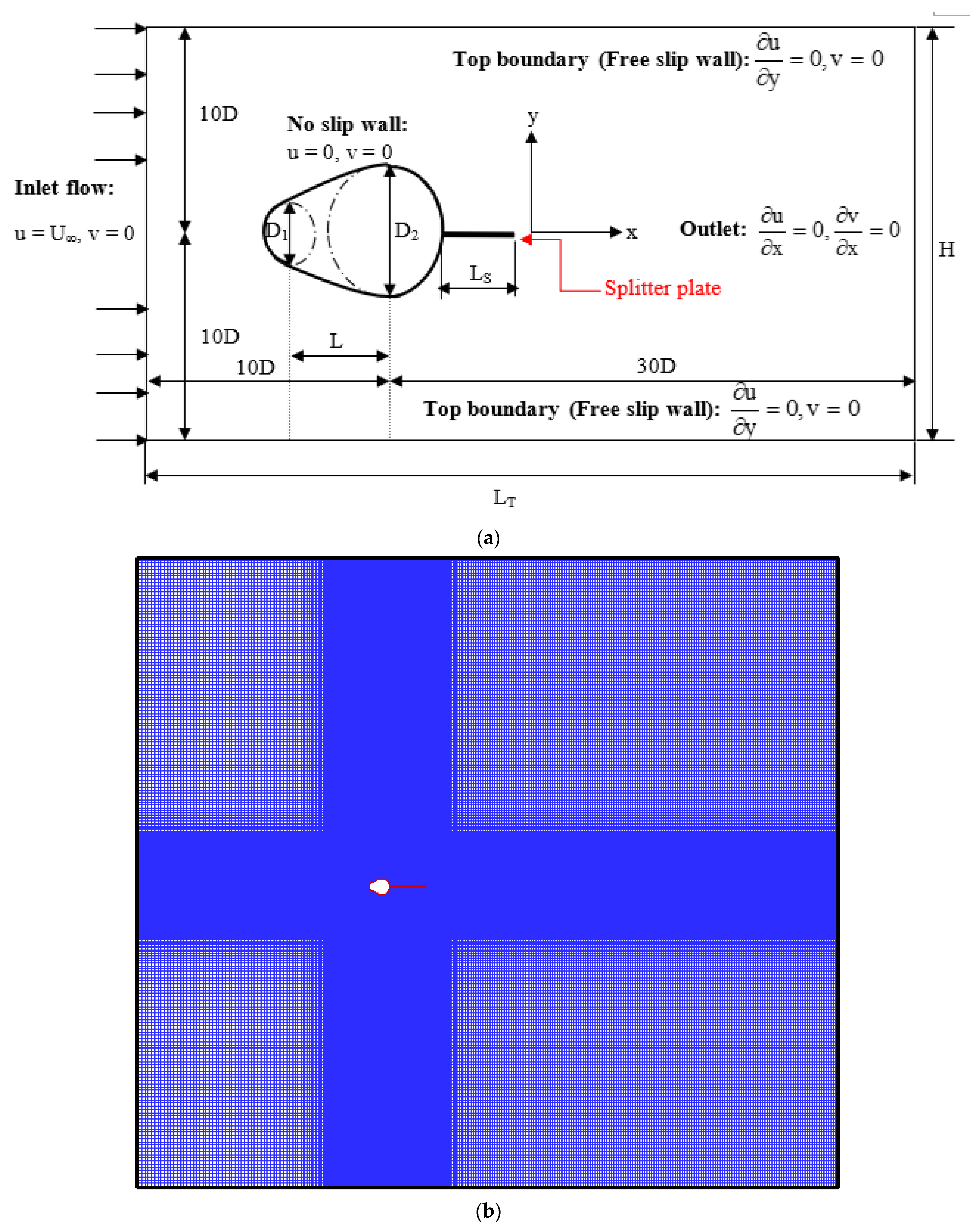
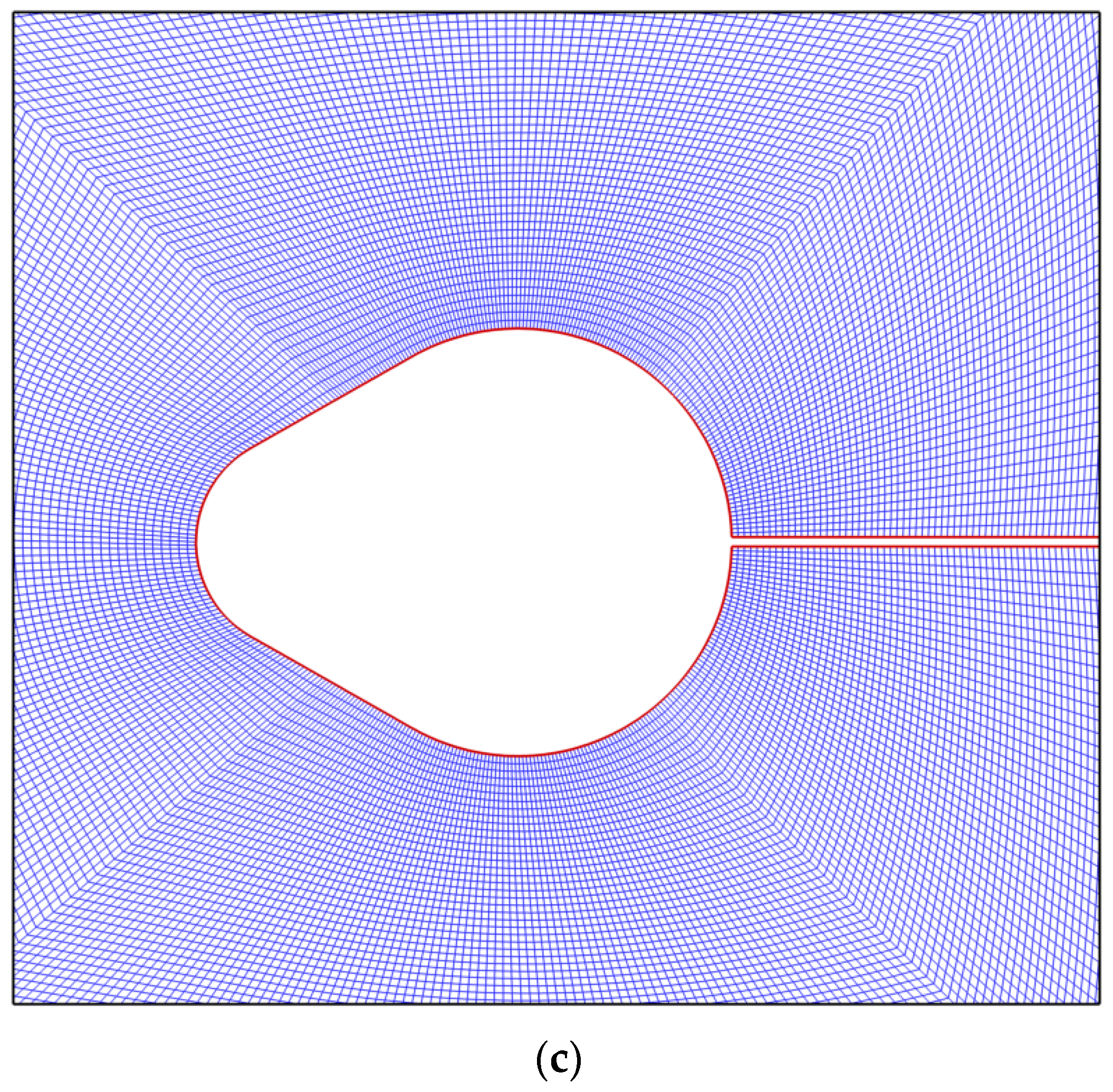
2. Computational Details and Validation Studies

Figure 1a shows the conceptual layout of the computational domain that was employed in this study to explore the flow around a cam-shamed cylinder combined with a backward splitter plate. The lateral, upstream, and downstream limits have adequate distance from the bluff body at 10D, 10D, and 30D, respectively, for flow around the cylinder to be unhindered by the blocking effect. D1/Deq is assumed to have an absolute diameter ratio of 0.455, while D2/Deq has a comparative diameter ratio of 0.8 and 0.9. In [1], it goes into detail about how the cam-shaped cylinder is made. The downstream side, or rear, of the bluff body, where the splitter plate is located, is designated by length LS. In the present research work, relative splitter plate length (LS/Deq) varies from 0.5 to 6.0.

2.1. Governing Equations and the Solving Method

For an incompressible, unstable flow, the governing equations are as follows:
The mass conservation equation is:
u x + v y = 0
Equation for momentum conservation in the direction of the x coordinate:
u t + u u x + v u y = 1 ρ p x + v ( 2 u x 2 + 2 u y 2 )
Equation for momentum conservation in the direction of the y coordinate:
v t + u v x + v v y = 1 ρ p y + v ( 2 v x 2 + 2 v y 2 )
where the x- and y-directional swiftness constituents, respectively, are denoted by u and v. The pressure in the indicated domain is given by p. The working fluid’s density (kg/m3) and kinematic viscosity (m2/s) are denoted by ρ and v, respectively.
At the inlet, the x-direction uniform flow boundary condition is satisfied. u = U and v = 0 are put into practice. No error boundary condition is used for the cylinder, along with a backward splitter plate. The top and bottom boundaries of the computational dominion are given slip flow boundary conditions. Computational domain outlet implemented with outflow flow boundary conditions.
A more detailed description of the boundary conditions used in the present computational domain is depicted in Figure 1a.
The governing equations listed above were solved using ANSYS-Fluent with the additional boundary conditions. Extents at cell faces are multiplied using a multidimensional linear re-establishment approach to achieve the second-order accuracy that is typically needed for the numerical calculations at this level of accuracy. For the creation of the necessary accuracy level, the cell-centered solution is expanded using the Taylor series around the cell centroid. Additionally, when using central-differencing techniques, it is possible to obtain boundless solutions and non-physical wiggles, which can cause stability problems in numerical simulations. By combining the postponed technique with the central-differencing system, this problem can be resolved. For the purpose of discretization, the second-order upwind and central difference techniques are used for the diffusive terms. In order to relate pressure and velocity, the semi-implicit technique for pressure-linked equations (SIMPLE) is used. When all of the normalized residual values are smaller than 10−10, the solutions are deemed to have converged.

2.2. Flow Parameters in Non-Dimensional Form

Hydrodynamic parameters in the non-dimensional form used in the current research work are indicated as follows:
In terms of Deq, the value of Reynolds number (Re) is defined as:
Re = UDeq/ν
The following equations produce the pressure coefficient (Cp) at the cylinder surface:
C p = ( p p ) 0.5 ρ U 2
Coefficients of lift and coefficients of drag are defined as:
C D = F D 0.5 ρ U 2 D eq   , C L = F L 0.5 ρ U 2 D eq  
where FD and FL are the forces operating in the streamwise and transverse directions, respectively, on the cam-shaped cylinder coupled to the rearward splitter plate.
These criteria describe non-dimensional time:
t * = t U D e q
The lift coefficient (CL) time history is transformed using the Fast Fourier transform (FFT) to obtain the vortex flaking frequency, which is specified by the Strouhal number (St).
S t = f D e q U
Two-dimensional flow’s vorticity is computed as follows:
ω z = × u = v x u y
These criteria describe the non-dimensional vorticity:
ω z * = ω z D eq U
The following equations are used to determine the time average and RMS value for any parameter between time points t1 and t2.
ϕ avg = 1 t 2 t 1 t 1 t 2 ϕ d t
ϕ RMS = t 1 t 2 ( ϕ i ϕ avg ) 2
The average calculated after 10 complete cycles have been made.

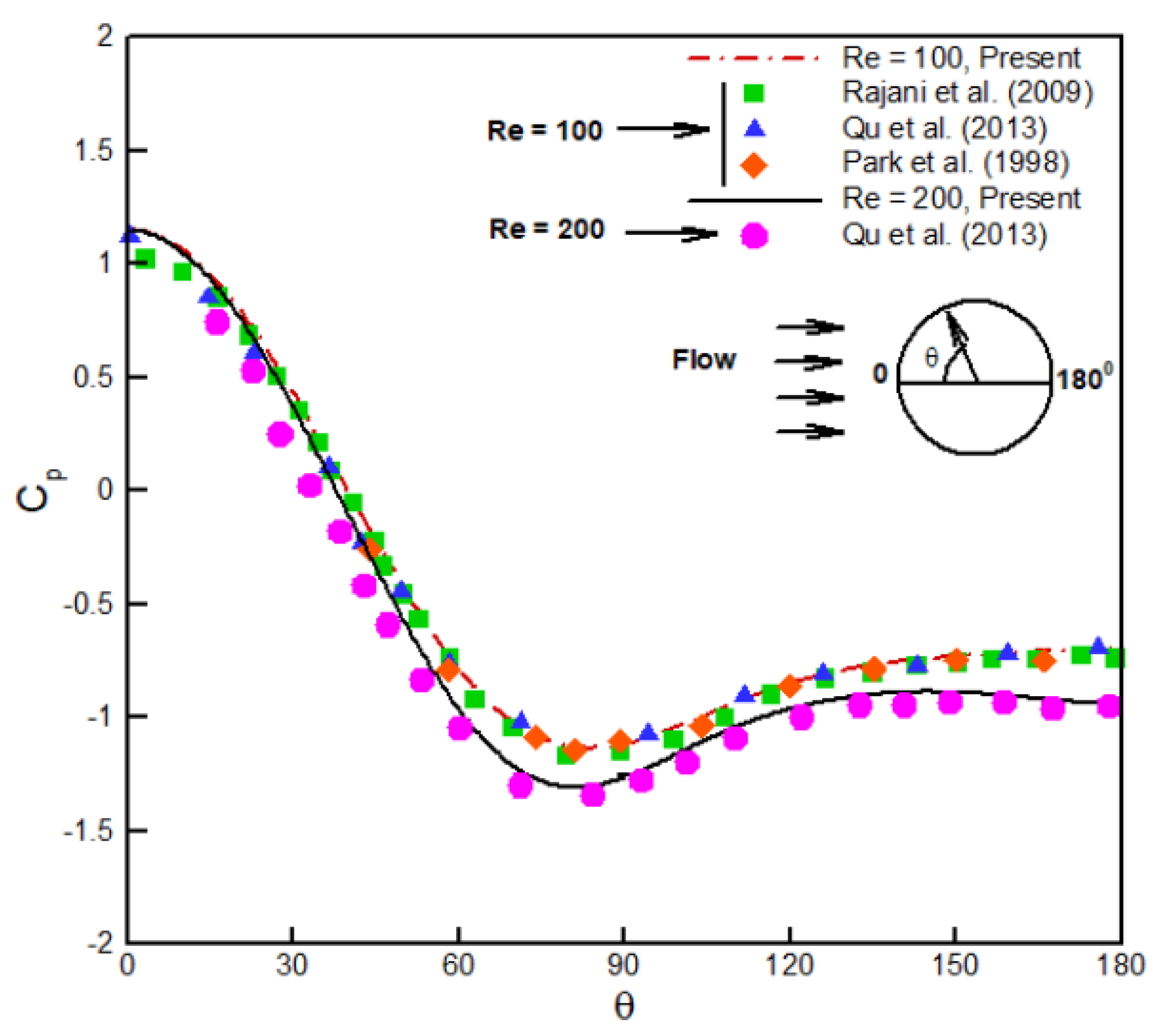
2.3. Mesh Independency and Validation

In the present investigation, we adopt a grid distribution that is not uniform, with more dense grid point clustering in regions with steeper flow gradients. Using the two grid types depicted in Figure 1, the ICEM module of ANSYS is utilized to discretize the computational domain. The O-type grid is chosen to be close to the cylinder, while the Cartesian grid is used in the other area. With more than 400 grid points, the cam-shaped cylinders attached to the backward splitter plate are discretized. The cam-shaped cylinder’s first layer grid is fixed at 0.004Deq in the wall-normal track, and the stretching ratio is roughly 1.1. The cam-shaped cylinder is encircled by a grid consisting of 200 discrete levels. However, the greatest grid size of 0.75Deq is employed regardless of a cam-shaped grid.
At Re = 100 and Pr = 0.7, mesh-independent results are produced using three sets of grids: 1.5 × 10⁵, 2.3 × 10⁵, and 3.28 × 10⁵. Average values for the drag coefficient (CD) and the Strouhal number (St) have percentage variations that are less than 1%. All simulation runs are performed using the largest grid size of 3.28 × 10⁵ cells for optimal accuracy. In all simulations, a shorter time step of Δt = 0.00285 is taken into account to produce more accurate findings.
The present numerical technique is validated using the pressure coefficient (CP), drag coefficient (CD), lift coefficient (CL), and Strouhal number (St) values for a single circular cylinder. The average Cp values are exposed in Figure 2, and they are in decent agreement with the data that are currently available in the literature.
Also computed and compared with the information from the literature in Table 1 are St, CD, and CL. The current findings are in line with those documented in the literature. By establishing laminar flow, the validity of the current numerical technique for modeling fluid flow through cylinders and other curved bluff structures is established.

3. Results and Discussion

At Re = 100, the shear layers on the back side of a cam-shaped cylinder split at the top and bottom curves. The two large vortices seen in Figure 3 were fed vorticity by these separate shear layers, which entrain fluid from surrounding irrotational flow. The split shear layers are curled by the low-pressure area at the back of the cam-shaped cylinder, which diverts the two main vortices inward and causes splashback on the cylinder base. Small wall-adhering vortices were thus created. When one of the primary vortices’ associated curled splitting shear layers influences the flow from the opposing side of the wake centerline, the vortex’s growth stops and it begins to compress. The other main vortex then coalesces with one of the walls adhering vortices, as seen in Figure 3. Islam et al. [10] reported a finding quite similar to this for a square cylinder case. Therefore, in order to modify the wake regime downstream of the cam-shaped cylinder, the vorticity distribution and vortex development must be altered. As a passive flow separation control device, a backward splitter plate delays the roll-up of the shear layers and modifies the pressure distribution and vorticity of the flow field. It is often mounted to the back side of the cylinder. Therefore, a backward splitter plate with a length range of 0.5Deq to 6Deq is taken into consideration in the current study effort. This very long splitter plate is enough to prevent vortex shedding and regulate flow.

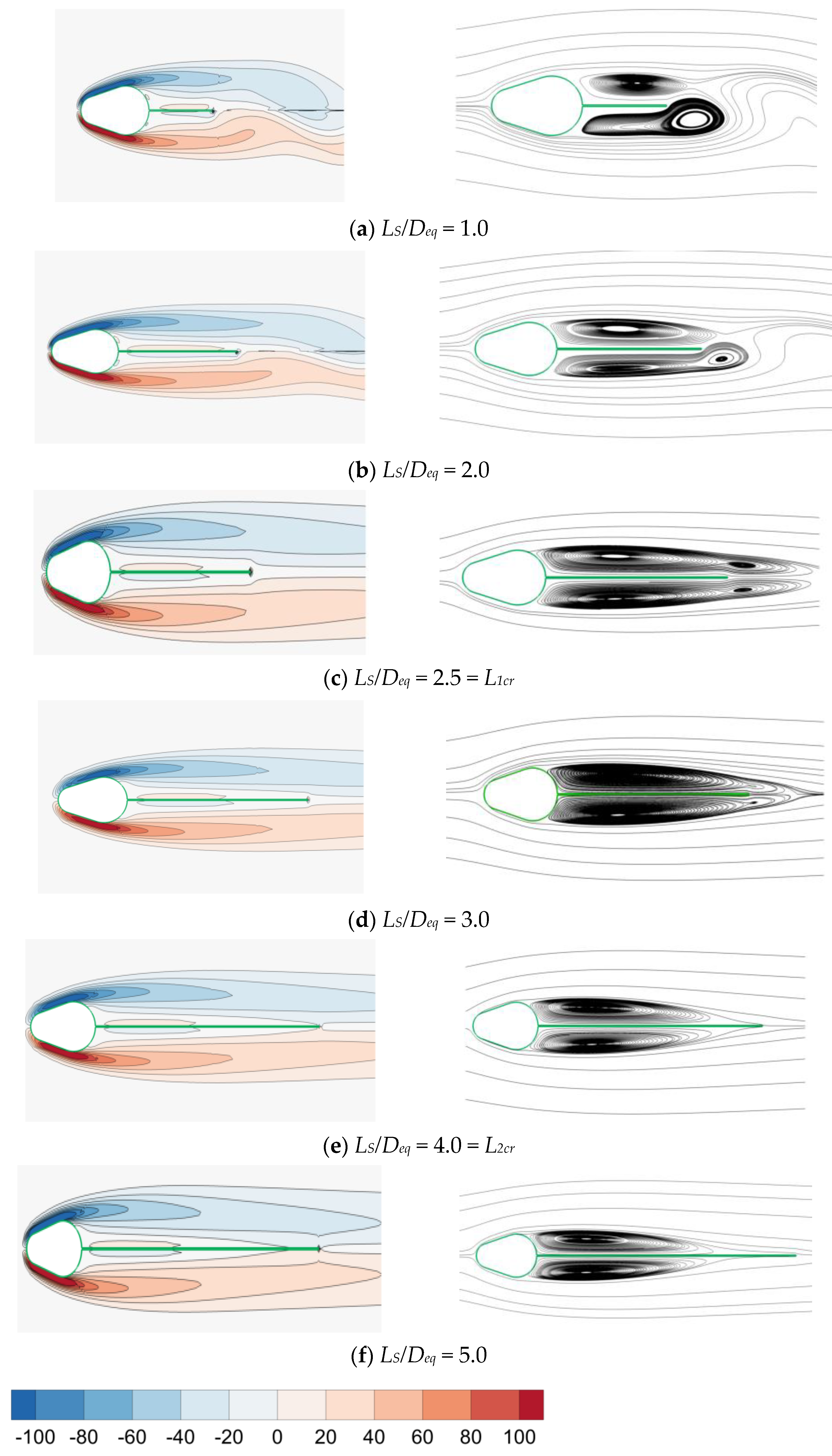
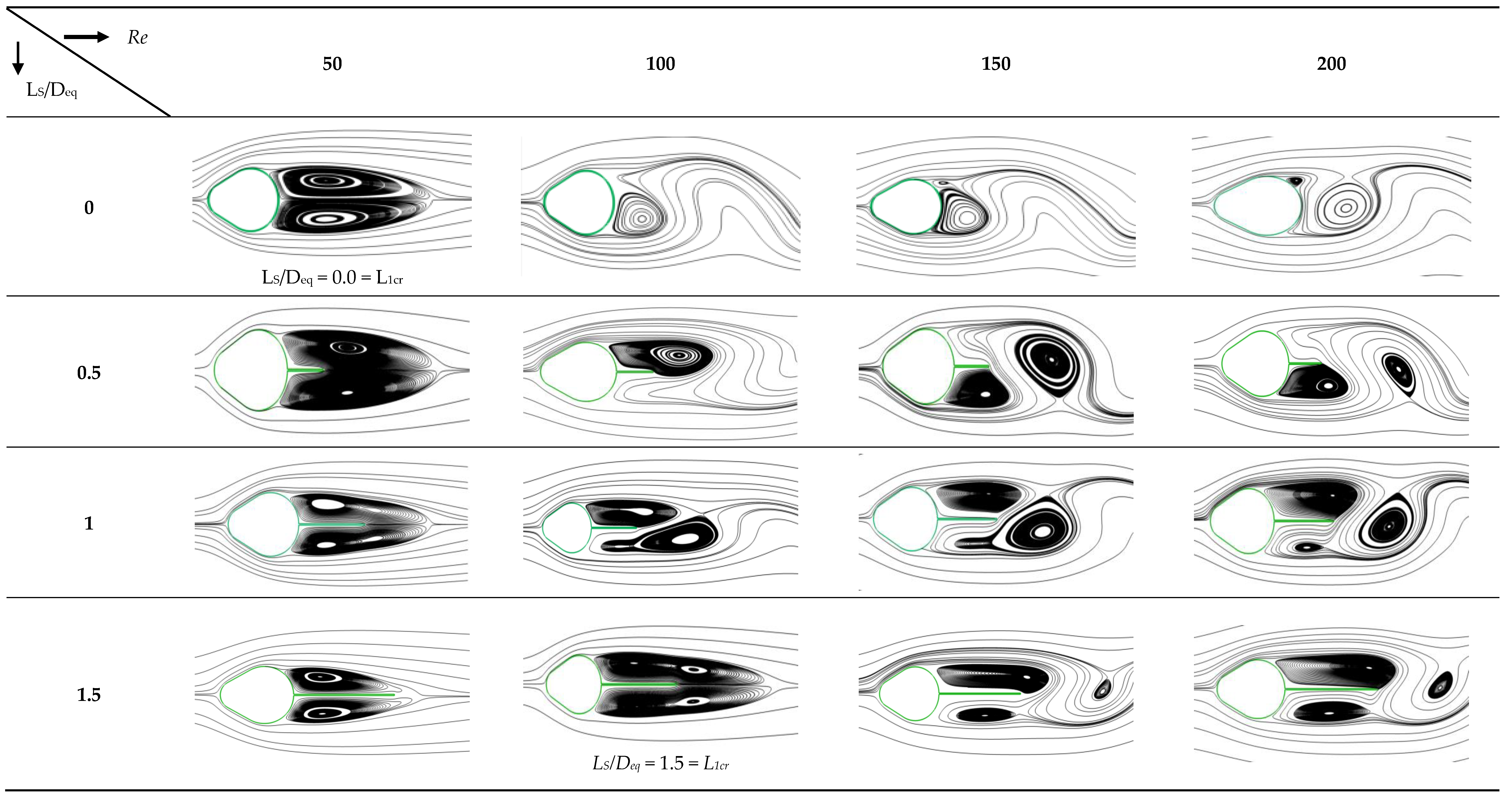
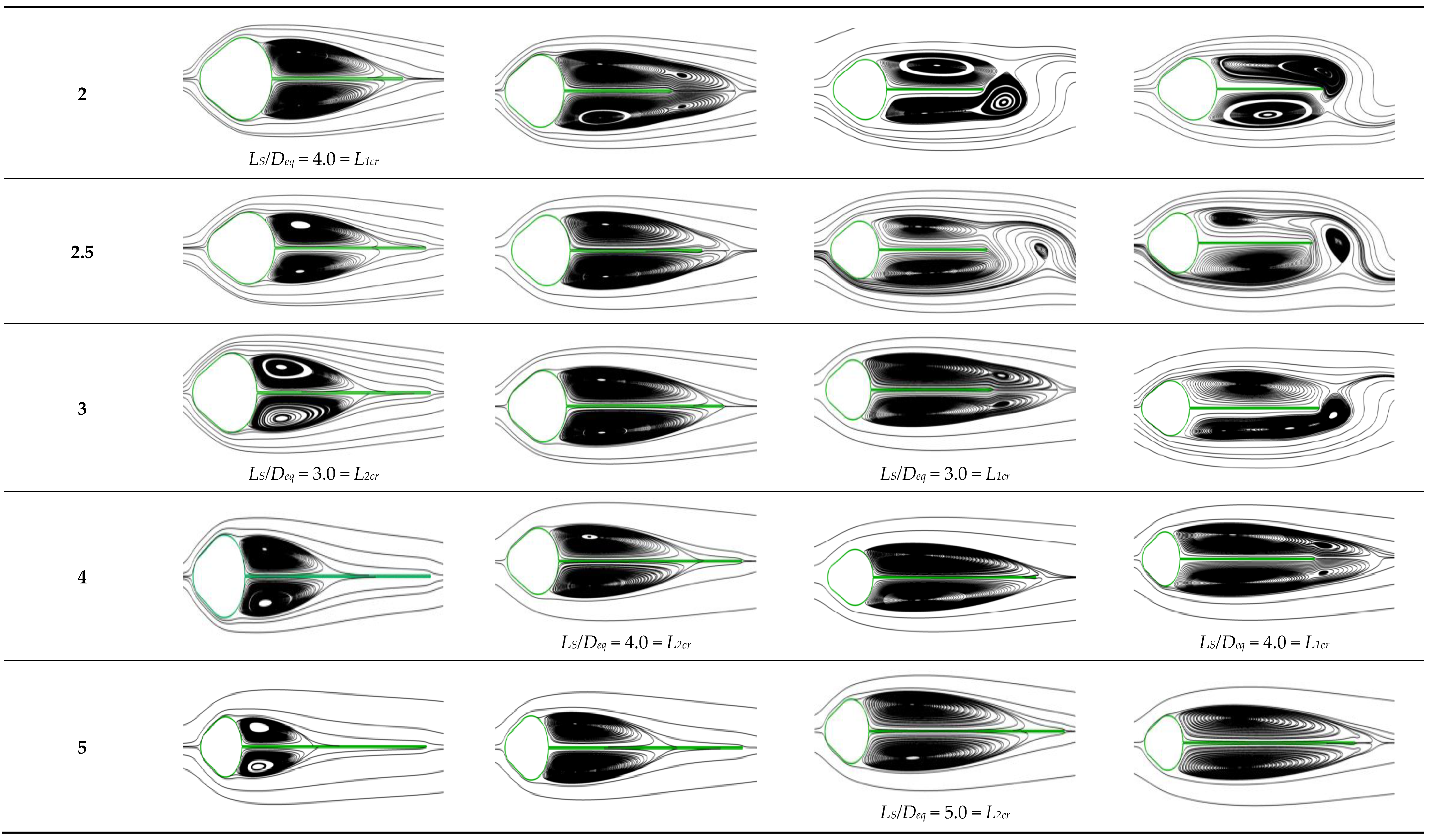
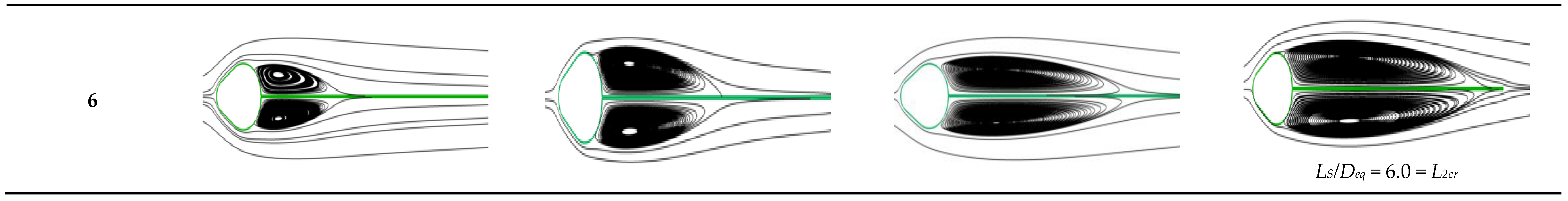
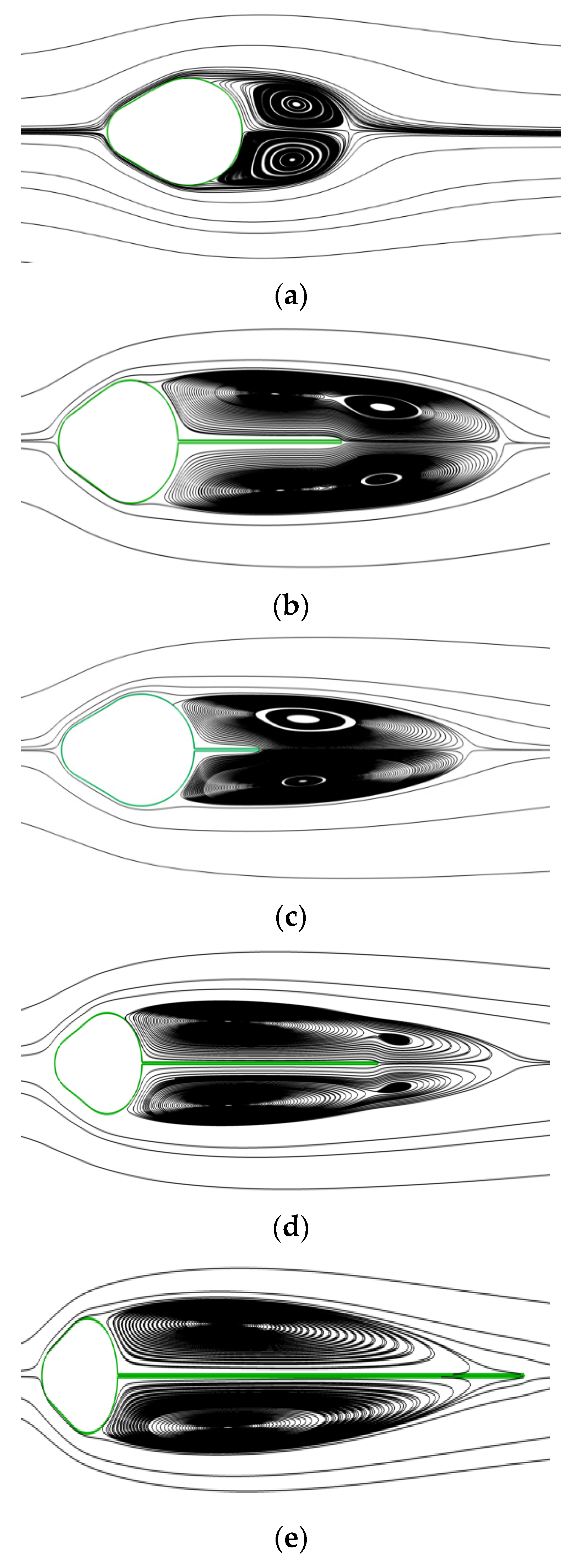
3.1. Flow Regime and Fluid Flow Characteristics

With the aid of instantaneous vorticity outlines and instantaneous rationalizes, the impact of splitter plate length on the fluid flow features of a cam-shaped cylinder embedded with a backward splitter plate is addressed. These flow behaviors are shown in Figure 4 and Figure 5, respectively, for D1/Deq = 0.455, D2/Deq = 0.8, and D1/Deq = 0.455, D2/Deq = 0.9, at Re = 200. In the current flow regime, the flow is classified as either unsteady flow (USF), in which vortices shed, or steady flow (SF), in which no vortices shed. L1cr and L2cr are two important splitter plate lengths for the specific flow regime. The minimum splitter plate length at which the flow switches from USF to SF is known as L1cr. In addition, the shear layers reattach to the plate once the length of the plate has been elevated to a certain point, the splitter plate prevents their contact, and recirculation bubbles develop on both sides of the plate. The recirculation length must be either shorter than or equivalent to the plate length. L2cr, or shear layer interaction inhibition (SII), is the minimum plate length needed to characterize it. The L1cr and L2cr are evidently at 2.5 and 4, respectively, in Figure 4. In addition, the values of L1cr and L2cr change to 4 and 6, respectively, when D2/Deq increases from 0.8 to 0.9. This is because the diameter of the back side of the cam-shaped cylinder that is attached to the backward splitter plate has increased. This increase prevents the shear layer from interacting; hence, a longer splitter plate is needed to prevent twister shedding.
Re and Ls/Deq combined impact on instantaneous streamlines is shown in Figure 6 for D1/Deq = 0.455 and D2/Deq = 0.9. The splitter plate significantly alters the wake regime, as is seen from Figure 6. Furthermore, it is discovered that when Re increases, a longer splitter plate is needed to suppress both twister shedding (L1cr) and shear layer contact (L2cr).
The distributions of the mean and instantaneous vorticities in the cam-shaped cylinder close to the wake zone vary because of the splitter plate’s wall boundary impact and the rearward splitter plate. Due to the redistribution of the vorticity field, the split shear layers deflected differently, which modified the wake region’s flow properties (pressure and velocity) as well as how the vortex evolved. Based on the average flows of the splitter plate, we separated the wake regime into five different types of flow patterns (flow pattern I, flow pattern II, flow pattern III, flow pattern IV, and flow pattern V).
The first two regimes are referred to as unsteady flow (USF), whereas the subsequent regimes are referred to as constant rate of flow (SF). Both the immediate and time-averaged streamlines look the same under the SF regime. In the first regime, two recirculation bubbles form in the wake area. Individual recirculation bubbles are identified by a single core (SC), which is also known as flow pattern 1 and specified as USF-SC, according to Figure 7a. In Regime 2, each recirculation bubble has a wake zone with two cores (DC—double core). Flow pattern 2, designated USF-DC in Figure 7b, serves as a representation of the usual regime-2 pattern. In regime 3, shear layer contact, a single core, and steady flow are all present. In Figure 7c, the typical flow pattern 3 is labeled as SF-SC-SIE.
Within the recirculation length in regime 4, a splitter plate is in touch with the shear layer, but the flaking of twisters in the downstream is not seen. But in this environment, two centers for every recirculation bubble are visible, as seen in Figure 7d. Regime-4’s official name is Regime 4, and its associated flow pattern is SF-DC-SIE. Strong shear effects, which are present in regimes 2 and 4, may be the cause of the splitting of single vortex cores (SC) into double vortex cores (DC), which is observed in these regimes. Single vortex core (SC) recirculation bubbles appear in regime 5 on both sides of the plate. Reattaching the shear layers to the plate’s surface prevents them from interacting with one another (SII). In this flow pattern, the recirculation length would either be precisely equal to the plate length or shorter. SF-SC-SII is the definition of the usual flow pattern for regime 5, commonly known as Regime 5, and it is shown in Figure 7e.
For all the studied cases, flow patterns and space diagrams for different values of Re, Ls/Deq and D1/Deq = 0.455, D2/Deq = 0.9, and D1/Deq = 0.455, D2/Deq = 0.8 are represented in Figure 8a,b, respectively. According to Figure 4, Figure 5, Figure 6, Figure 7 and Figure 8, the splitter plate attachment alters the vortex creation process, narrows the wake zone, and lengthens the twister formation region, which reduces the frequency of vortex flaking.

3.2. Time Average Wake Length and Wake Centerline Velocity Distribution

Figure 9a,b, which show the time average vortex recirculation length (Lw/Deq) as a function of Re and Ls/Deq for D1/Deq = 0.455, D2/Deq = 0.9, and D1/Deq = 0.455, D2/Deq = 0.8, respectively. It has been shown that the wake length grows as the splitter plate length increases, reaches a maximum value at L1cr, and then begins to decrease. Up until L2cr, there is a reduction in wake length, while following increases in splitter plate length have no impact on wake length. Additionally, the wake duration shortens when D2/Deq falls from 0.9 to 0.8. This is because shear layer interaction is present.
Plotting the wake centerline velocity for an unaltered cam-shaped cylinder allows us to examine the recirculation zone or wake separation bubble impacts of the splitter plate, and this is depicted in Figure 10. The area of momentum deficit, or separation bubble, which is present immediately downstream of the unaltered cam-shaped cylinder, has a time-averaged velocity that is negative. In this instance, the space between the center of the cam-shaped cylinder and a point along the wake centerline at which the sign of the time-average velocity changes from negative to positive is used to calculate the length of the recirculation wake. Stasis point is the term used to describe this velocity sign change point. The flow within the wake is traveling in the cam-shaped cylinder’s direction and will arrive at its maximum returning velocity somewhere along the wake axis. For all combinations of D1/Deq and D2/Deq, it has been discovered that the maximum returning velocity decreases with increasing splitter plate length. The amplitude of frequent speed in the cylinder downstream diminishes with each incremental splitter plate length increase, and no negative values for rear axis velocity are seen. This shows that the formation of vortices at the plate’s trailing edge is not caused by direct interaction between shear layers. The distance between the base of the cam-shaped cylinder and the stagnation point is known as the vortex formation length. It has been shown that vortex formation length increases along with plate length.

3.3. Time Average Drag

This section discusses the average drag coefficient variation for various values of Re, Ls/Deq, and D2/Deq. Generally, changing the flow regime has an impact on the values of Cd-avg. However, if the recirculation length changes due to interactions between the splitter plate and shear layer with the same sort of flow regime, the Cd values may also be impacted. Larger Cd values are often seen for flow pattern I flow regimes, and the values fall when one sort of flow regime gives way to another. The lowest Cd levels are seen in the Type V flow pattern regime. A further observation from Figure 11 is that the Cd average value constantly declines as plate length grows until the splitter plate length reaches L2cr, at which time it starts to climb. For instance, at Re = 200, Ls/Deq = 6 yields the lowest value of Cd. The average drag initially rises with longer splitter plates until Ls/Deq = 2, at which point it starts to decrease. Complex interactions between the splitter plate and cam-shaped cylinder in the low Reynolds number flow (Re = 50) affect this behavior. Initially, the increase in surface area improves flow attachment, which lowers drag, but excessive length may cause flow separation, which raises drag. This underlines the complex link between the length of the splitter plate and the reduction of drag in low Reynolds number flows.
The splitter plate lies inside the recirculation vortex zone up to Ls/Deq = L2cr, where fluid flow is carried in the opposite direction from the main fluid flow towards the body, which results in the Cd average trend with splitter plate length. As a result, a force component associated with skin friction that is perpendicular to the main drag direction appears. Increasing the splitter plate length Ls/Deq > L2cr results in more viscous drag because a portion of the plate is left outside the recirculation twister zone. These predictions show that in order to obtain the lowest Cd average, the plate length at Lw at L2cr should be accurate. Additionally, it has been shown that the Cd average decreases as the Re value increases. This may be explained by diminished viscous effects, delayed boundary layer separation, and smoother flow transitions at higher Re; the Cd average decreases with rising Re. This transition results in less pressure drag and enables more streamlined body shapes, which helps reduce drag overall. Further, due to the cylinder’s more streamlined design, high Cd average values are also seen for D2/Deq of 0.9 cylinders.

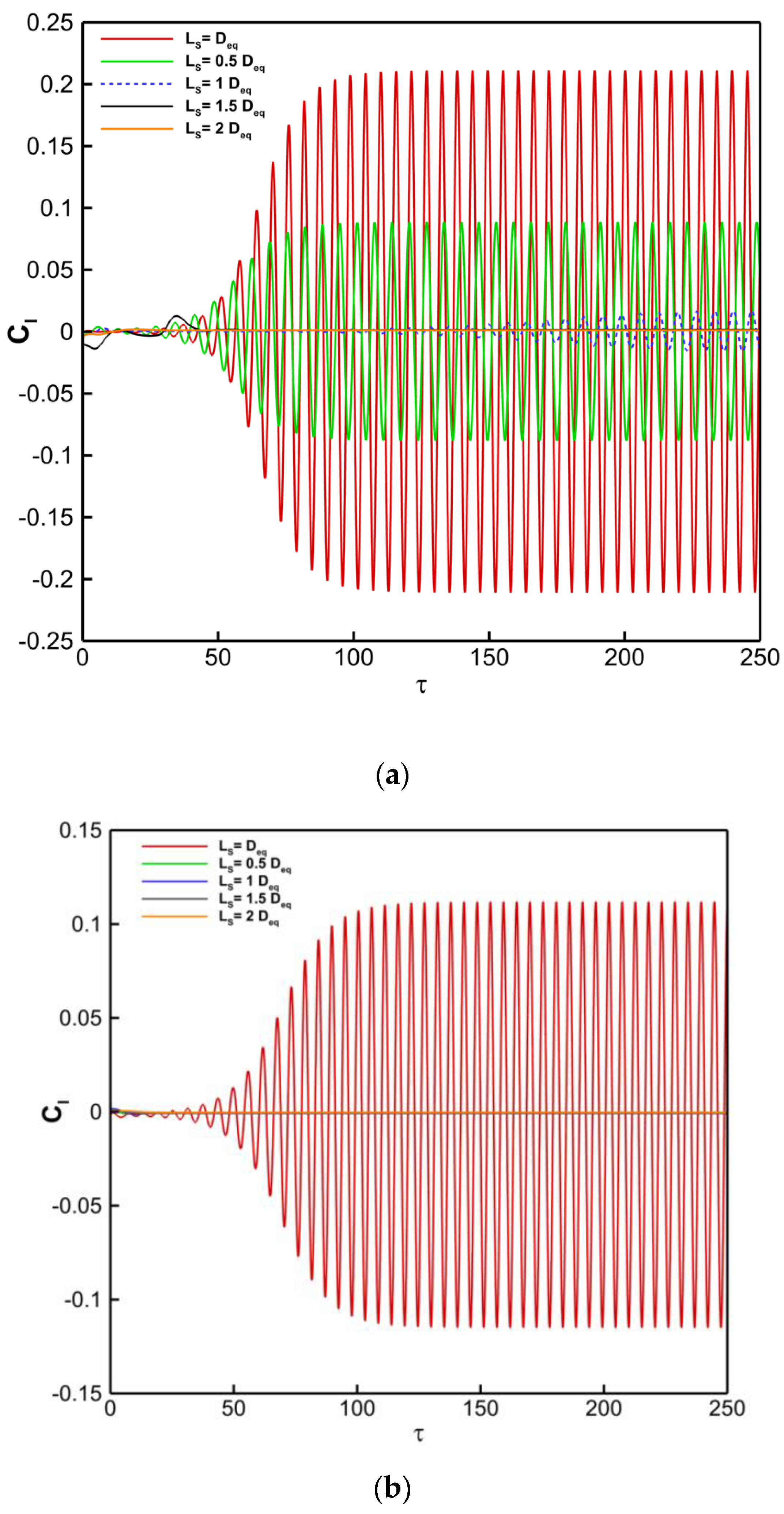
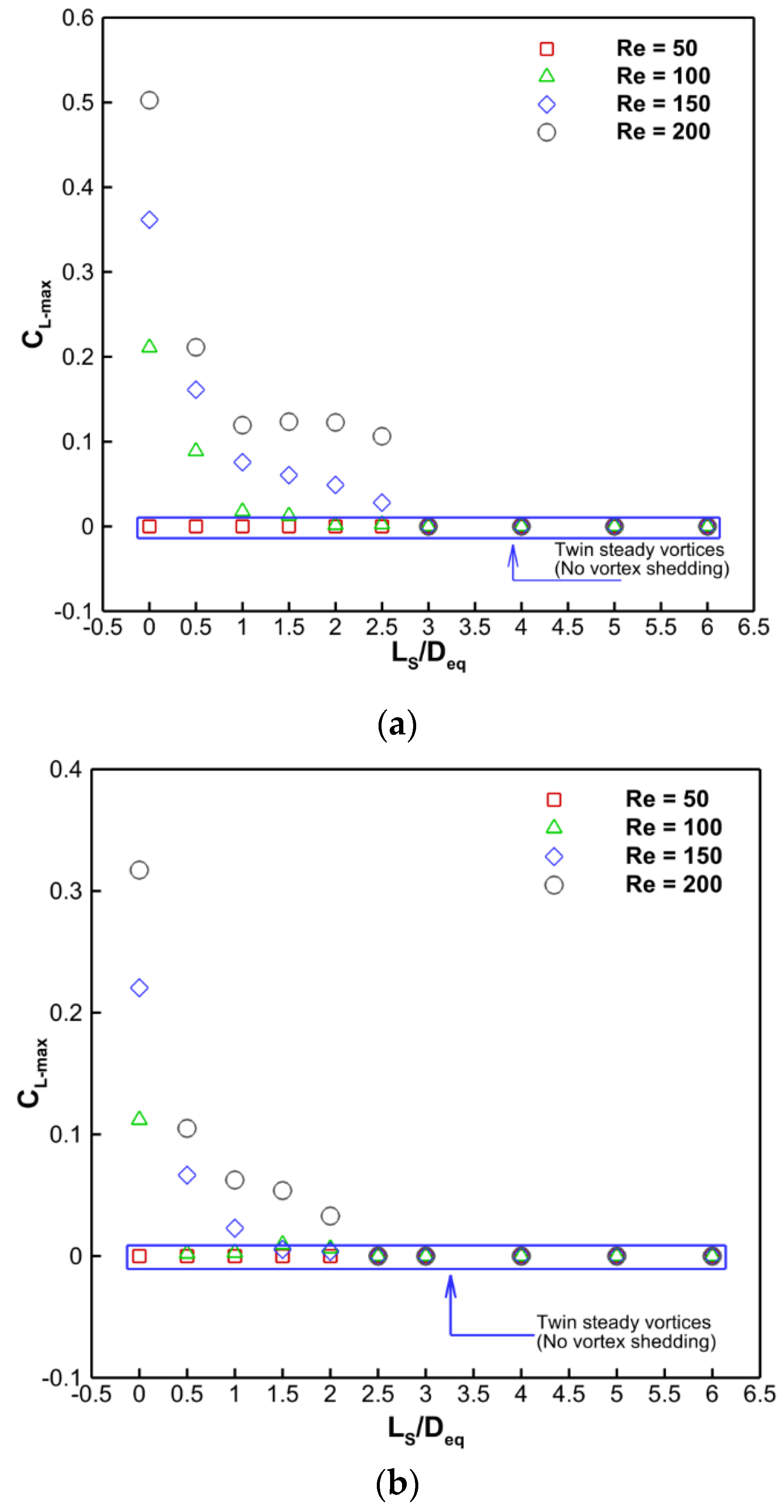
3.4. Lift Forces Evolution and Maximum Lift Coefficient

Fluid forces acting on the surface and splitter plate of the cam-shaped cylinder fluctuate as vortices alternately shed from the cylinder. The evolution of lift coefficient (Cl) through time is shown in Figure 12 under the conditions of Re = 100, Ls/Deq, D1/Deq = 0.455, D2/Deq = 0.9, and D1/Deq = 0.455, D2/Deq = 0.8. Since the flow is constant in both instances, Figure 12 shows the longer plate length. The graphic clearly shows that the amplitude of lift development decreased when D2/Deq went from 0.9 to 0.8. If there is no lift evolution, the flow is stable, there is a symmetrical vortex behind the cylinder, and there is no consequent active force in the wake field normal to the fluid flow route. As the length of the splitter plate increases, the same behavior is seen. Additionally, it was discovered that the lift curve exhibits periodic behavior and varies with the splitter plate lengths’ vortex shedding frequency up to Ls/Deq = L1cr. Cl frequency and amplitude both decrease with plate length until they reach zero at Ls/Deq = L1cr.
With varying values of Ls/Deq, Re, and D1/Deq = 0.455, D2/Deq = 0.9, and D1/Deq = 0.455, D2/Deq = 0.8, respectively, Figure 13a,b show the fluctuation of the maximum lift coefficient (CL-max). Therefore, the pressure is lowest on the side furthest from the source of the vortices and highest on the side towards the center. Therefore, the forces operating on the body fluctuate, and the lift force that results in oscillations on the body has a frequency equivalent to the vortex’s shed frequency. It is obvious that as splitter plate length increases, the maximum lift coefficient value lowers until it reaches zero at Ls/Deq = L1cr. This is due to the fact that the flow is constant for this duration. Furthermore, when D2/Deq decreases from 0.9 to 0.8, the maximum lift coefficient magnitude decreases. Thus, it is abundantly obvious that the USF is associated with a greater maximum lift coefficient.

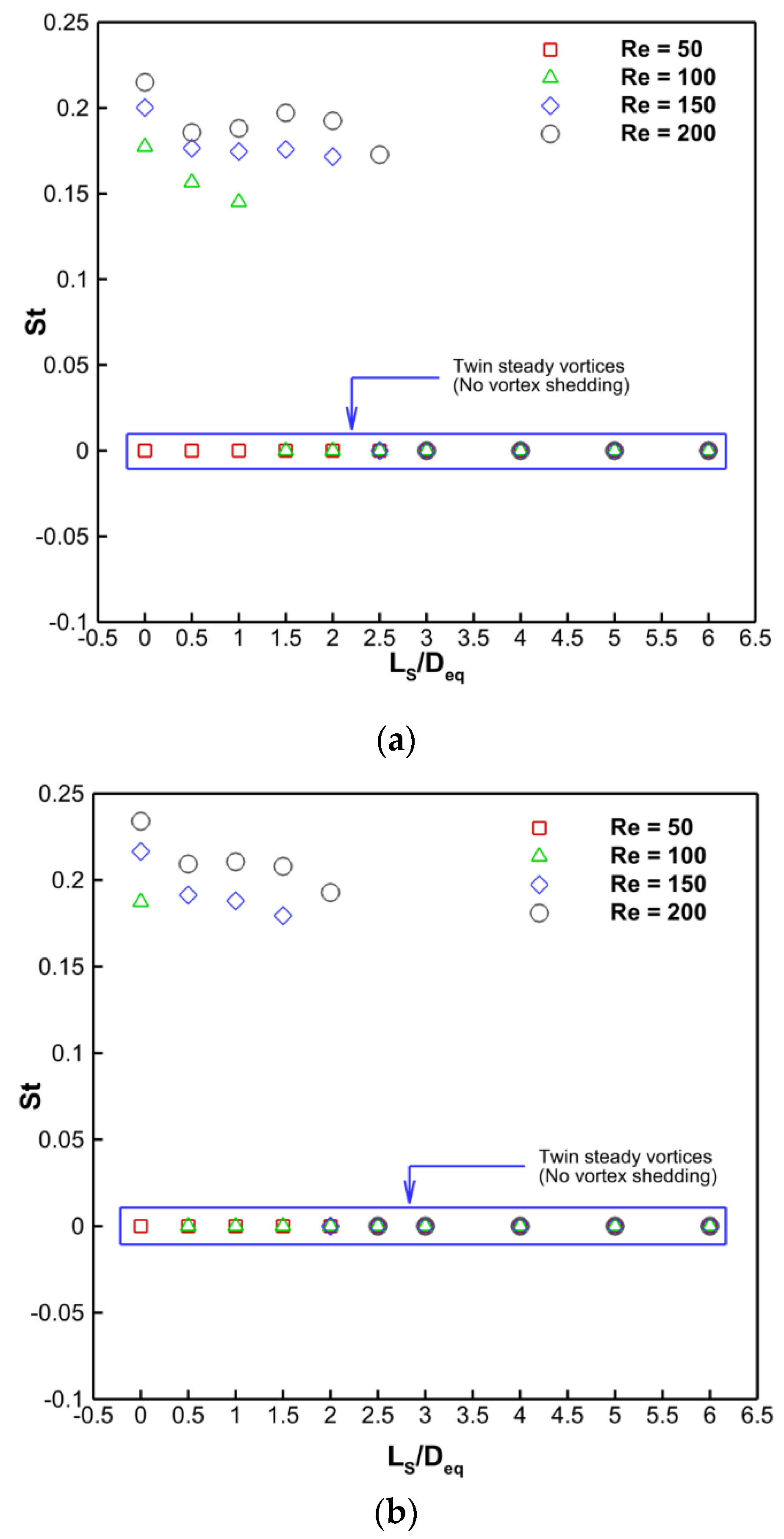
3.5. Frequency of Vortex Shedding

The Strouhal number (St), a non-dimensional quantity, is taken into consideration to reflect the frequency of vortex shedding. Figure 14 shows how Ls/Deq, Re, and D2/Deq affect the frequency of vortex shedding. The fluctuation of St with plate length is shown to portray various behaviors, and the evolution of lifts is also seen to follow a similar pattern. Additionally, St becomes zero under all conditions at a plate length of Ls/Deq = L1cr when vortex shedding suppression is seen.
Drag reduction using a splitter plate in the cam-shaped cylinder is compared with previous work, as presented in Table 2. The results are compared at a Re of 100 in the laminar flow regime. The last column in Table 2 depicts the percentage reduction in drag for the present geometry compared to other studies. It is found that there is a drag reduction of approximately 15.94% and 1.21% when using the cam-shaped cylinder with the attached backward splitter plate in comparison to the circular cylinder and elliptical cylinder with the attached backward splitter plate, respectively.

4. Conclusions

Re = 50 to 200 has been varied in the current numerical investigation to do a parametric study of the flow through a cam shape with D1/Deq = 0.455, D2/Deq = 0.8, and 0.9. The backward splitter plate’s length (Ls/Deq) can be any value between 0.0 and 6.0. The splitter plate modifies the wake zone while lowering vortex shedding and preventing shear layer contact. Utilizing streamlines and vorticity contours, there are five distinct regimes of fluid flow patterns and two fundamental lengths. Upon increasing the plate length from Ls/Deq to L2cr, regime-1 changes to regime-5. The following are some of the main conclusions of the current investigation:
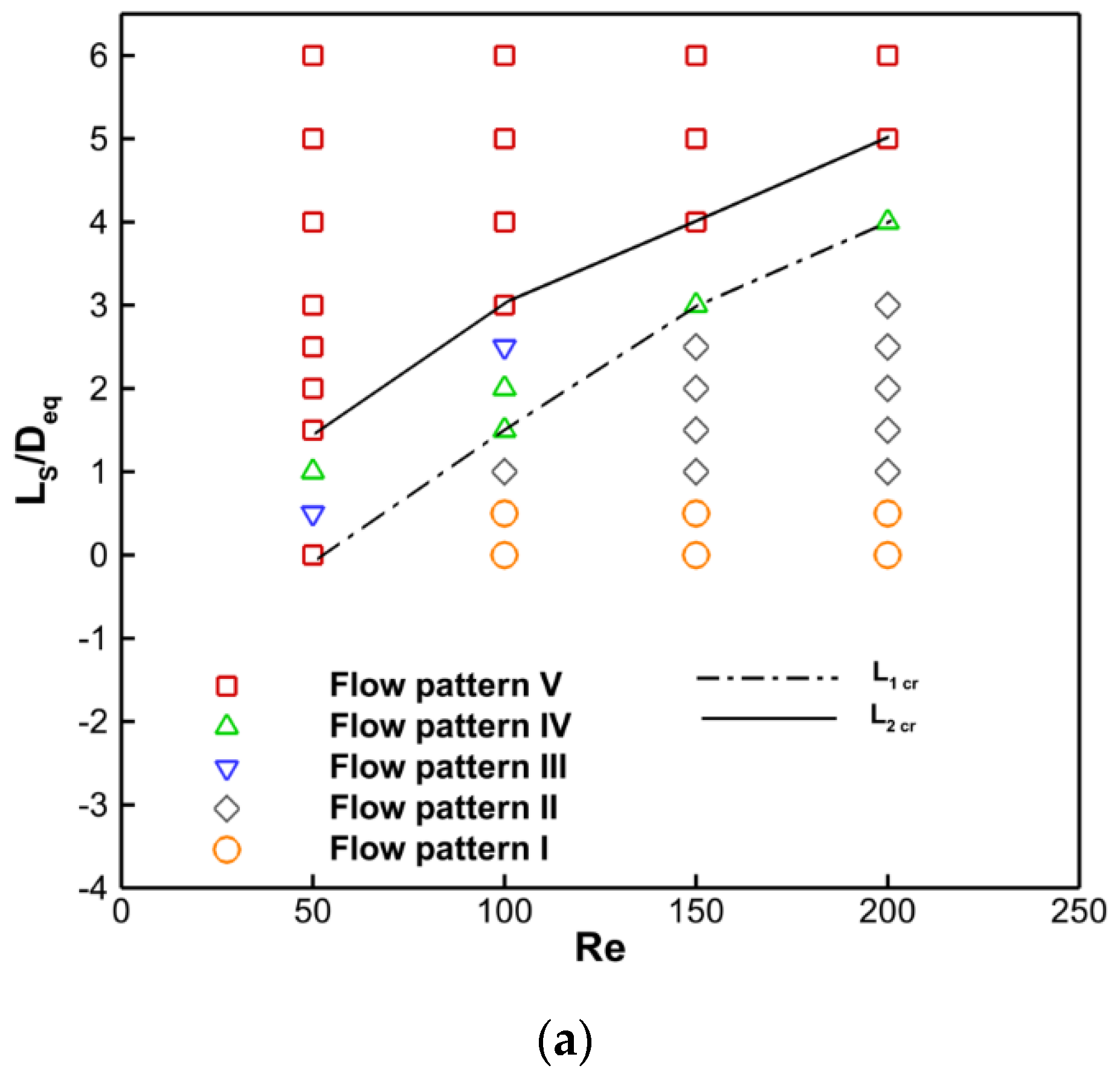
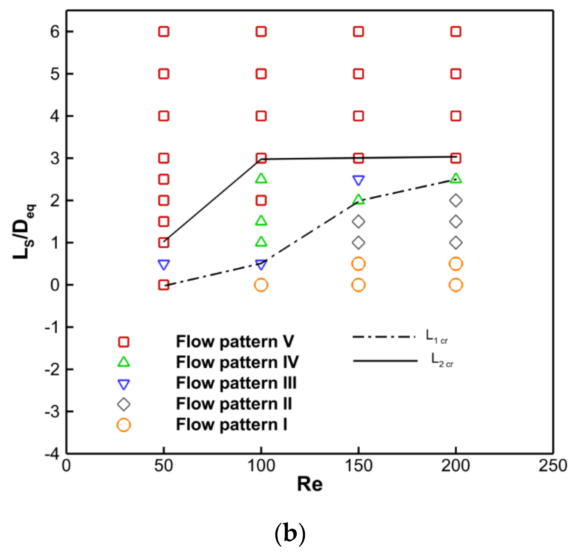
  • There are certain values for L1cr and L2cr at which every combination results in the suppression of the vortex and the avoidance of the shear layer interaction of D2/Deq and Re;
  • For larger values of D2/Deq and Re, longer splitter plates are required for the inhibition of shear layer contact (L2cr) as well as the suppression of vortex shedding (L1cr);
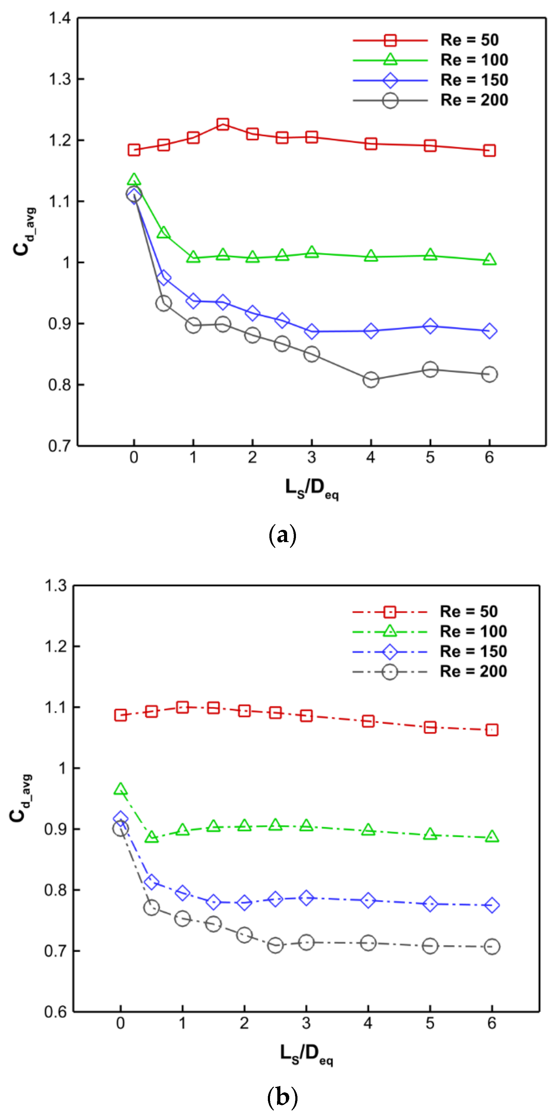
  • There is no monotonic connection between drag, maximum lift, and vortex shedding frequency as the splitter plate’s length changes;
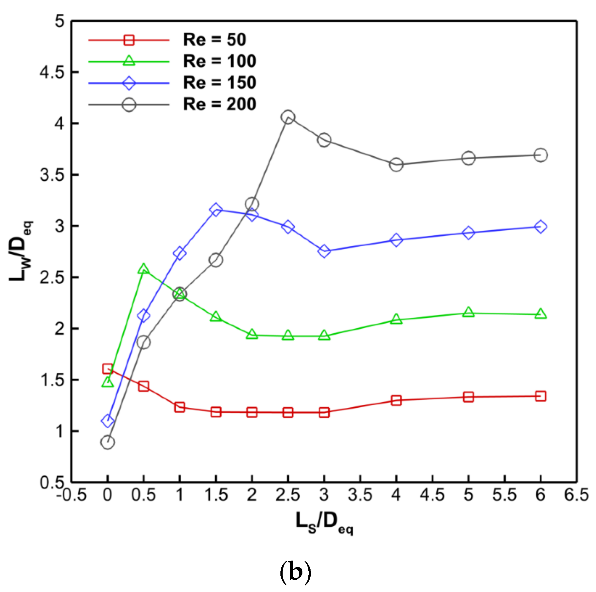
  • The recirculation wake length obtained at L2cr is the perfect length for the splitter plate to achieve the least amount of drag;
  • For larger values of Re, the rearward splitter plate and cam-shaped cylinder combination reduce drag by a greater amount;
  • Recirculation wake length and vortex formation length stay constant as splitter plate length increases until Ls/Deq = L1cr once Ls/Deq > L1cr for all combinations of D2/Deq and Re;
  • In order to effectively restrict vortex shedding and reduce drag, it was discovered that the splitter plate inserted behind the cam-shaped cylinder serves as a suitable passive control mechanism. In cam-shaped cylinders and bluff bodies, this device can be employed to reduce drag.

Author Contributions

S.C.: Led the project with conceptualization, methodology, software development, validation, data investigation, resource management, and writing. Also, provided critical input during the review and editing process, created visualizations, supervised the project, and secured funding. A.J.: Contributed to the project by refining the conceptualization, implementing methodology, conducting investigations, and curating data. Also, played a role in data visualization. S.R.: Assisted in software development, conducted investigations, and contributed to the review and editing of the manuscript. S.G.: Provided formal analysis and contributed to the initial drafts of the manuscript. A.G.: Conducted formal analysis and contributed to the early drafts of the manuscript. S.B.: Collaborated in conceptualization, methodology development, and investigations. S.E.-a.: Played a key role in software development, validation, data investigation, resource management, and manuscript creation. Also, contributed to the review and editing process and created visualizations. C.T.: Validated the findings, contributed to the initial manuscript drafts, provided supervision, and secured funding for the project. All authors have read and agreed to the published version of the manuscript.

Funding

Authors does not receive any funding support from any organization for this research work.

Data Availability Statement

Data will be made available on request.

Conflicts of Interest

The authors declared no conflict of interest with anyone for submitting/publishing of this manuscript.

Nomenclature

cpSpecific heat of fluid, J kg−1 K−1
CpTime averaged pressure coefficient
CdTotal drag coefficient
CLTotal lift coefficient
CL maxMaximum lift magnitude
D1The diameter of cylinder 1, in m
D2The diameter of cylinder 2, in m
DeqCam-shaped cylinder equivalent in diameter, having a perimeter equal to a cylinder of diameter equal to Deq, m
Deq1 = D1/DeqComparative equivalent diameter ratio of cylinder 1
Deq2 = D2/DeqComparative equivalent diameter ratio of cylinder 2
dPPressure drop, Pa
fVortex shedding frequency, s−1
FDDrag force per unit length of cylinder, N m−1
FLLift force per unit length of cylinder, N m−1
HHeight of the computational domain, m
kThe fluid’s thermal conductivity, in W m−1 K−1.
LThe distance between the centers of the cylinders 1 and 2 is m.
LeqEquivalent cylinders spacing
LTThe length of the computing area, m
LWLength of wake or recirculation, m
n ^ Direction normal to the cylinder surface
pPressure, N m−2
pFree stream pressure, N m−2
PrPrandlt number
ReReynolds number
StStrouhal number
TPOne periodic cycle time, s
TTime, s
t*Non-dimensional time
UUniform velocity at the inlet, m s−1
UComponent of velocity in the x-direction, m s−1
VVelocity component in the y-direction, m s−1
XStream-wise coordinate, m
YTransverse coordinate, m
Greek symbols
µViscosity of the fluid, kg m−1 s−1
ΡDensity of the fluid, kg m−3
ΘAngle around the cylinder, degree
ωz and ω*zDimensional and non-dimensional vorticity
Abbreviations
FVMFinite volume method
FFTFast Fourier transform
RMSRoot mean square

References

  1. Chamoli, S.; Tang, T.; Yu, P.; Lu, R. Effect of shape modification on heat transfer and drag for fluid flow past a cam-shaped cylinder. Int. J. Heat Mass Transf. 2019, 131, 1147–1163. [Google Scholar] [CrossRef]
  2. Choi, H.; Jeon, W.-P.; Kim, J. Control of flow over a bluff body. Annu. Rev. Fluid Mech. 2008, 40, 113–139. [Google Scholar] [CrossRef]
  3. Rashidi, S.; Hayatdavoodi, M.; Esfahani, J.A. Vortex shedding suppression and wake control: A review. Ocean. Eng. 2016, 126, 57–80. [Google Scholar] [CrossRef]
  4. Zdravkovich, M. Review and classification of various aerodynamic and hydrodynamic means for suppressing vortex shedding. J. Wind. Eng. Ind. Aerodyn. 1981, 7, 145–189. [Google Scholar] [CrossRef]
  5. Zhang, K.; Katsuchi, H.; Zhou, D.; Yamada, H.; Han, Z. Numerical study on the effect of shape modification to the flow around circular cylinders. J. Wind. Eng. Ind. Aerodyn. 2016, 152, 23–40. [Google Scholar] [CrossRef]
  6. Gu, F.; Wang, J.; Zhao, Z.; Qiao, X. Pressure distribution and aerodynamics of circular cylinder with freely rotating fairings. J. Exp. Mech. 2012, 27, 368–376. [Google Scholar]
  7. Wang, J.; Zheng, H.; Tian, Z. Numerical simulation with a TVD–FVM method for circular cylinder wake control by a fairing. J. Fluids Struct. 2015, 57, 15–31. [Google Scholar] [CrossRef]
  8. Wu, H.; Sun, D.; Lu, L.; Teng, B.; Tang, G.; Song, J. Experimental investigation on the suppression of vortex-induced vibration of long flexible riser by multiple control rods. J. Fluids Struct. 2012, 30, 115–132. [Google Scholar] [CrossRef]
  9. Islam, S.-U.; Manzoor, R.; Islam, Z.-U.; Kalsoom, S.; Ying, Z.C. A computational study of drag reduction and vortex shedding suppression of flow past a square cylinder in presence of small control cylinders. AIP Adv. 2017, 7, 045119. [Google Scholar] [CrossRef]
  10. Islam, S.U.; Manzoor, R.; Ying, Z.C.; Rashdi, M.M.; Khan, A. Numerical investigation of fluid flow past a square cylinder using upstream, downstream and dual splitter plates. J. Mech. Sci. Technol. 2017, 31, 669–687. [Google Scholar] [CrossRef]
  11. Soumya, S.; Prakash, K.A. Effect of splitter plate on passive control and drag reduction for fluid flow past an elliptic cylinder. Ocean Eng. 2017, 141, 351–374. [Google Scholar] [CrossRef]
  12. Ul-Islam, S.; Zhou, C. Characteristics of flow past a square cylinder using the lattice Boltzmann method. Inf. Technol. J. 2009, 8, 1094–1114. [Google Scholar] [CrossRef]
  13. Ali, M.S.M.; Doolan, C.J.; Wheatley, V. Grid convergence study for a two-dimensional simulation of flow around a square cylinder at a low Reynolds number. In Proceedings of the Seventh International Conference on CFD in The Minerals and Process Industries, Melbourne, Australia, 9–11 December 2009; pp. 1–6. [Google Scholar]
  14. Tezel, G.B.; Yapici, K.; Uludag, Y. Numerical and Experimental Investigation of Newtonian Flow around a Confined Square Cylinder. Period. Polytech. Chem. Eng. 2019, 63, 190–199. [Google Scholar] [CrossRef]
  15. Tang, T.; Yu, P.; Shan, X.; Li, J.; Yu, S. On the transition behavior of laminar flow through and around a multi-cylinder array. Phys. Fluids 2020, 32, 013601. [Google Scholar] [CrossRef]
  16. Zhang, D.; Cheng, L.; An, H.; Draper, S. Flow around a surface-mounted finite circular cylinder completely submerged within the bottom boundary layer. Eur. J. Mech.-B/Fluids 2021, 86, 169–197. [Google Scholar] [CrossRef]
  17. Akilli, H.; Sahin, B.; Tumen, N.F. Suppression of vortex shedding of circular cylinder in shallow water by a splitter plate. Flow Meas. Instrum. 2005, 16, 211–219. [Google Scholar] [CrossRef]
  18. Sarioglu, M. Control of flow around a square cylinder at incidence by using a splitter plate. Flow Meas. Instrum. 2017, 53, 221–229. [Google Scholar] [CrossRef]
  19. Dai, S.; Younis, B.A.; Zhang, H.; Guo, C. Prediction of vortex shedding suppression from circular cylinders at high Reynolds number using base splitter plates. J. Wind. Eng. Ind. Aerodyn. 2018, 182, 115–127. [Google Scholar] [CrossRef]
  20. Rocchio, B.; Mariotti, A.; Salvetti, M. Flow around a 5: 1 rectangular cylinder: Effects of upstream-edge rounding. J. Wind. Eng. Ind. Aerodyn. 2020, 204, 104237. [Google Scholar] [CrossRef]
  21. Deng, J.; Mao, X.; Xie, F. Dynamics of two-dimensional flow around a circular cylinder with flexible filaments attached. Phys. Rev. E 2019, 100, 053107. [Google Scholar] [CrossRef]
  22. An, B.; Bergadà, J.; Mellibovsky, F.; Sang, W.; Xi, C. Numerical investigation on the flow around a square cylinder with an upstream splitter plate at low Reynolds numbers. Meccanica 2020, 55, 1037–1059. [Google Scholar] [CrossRef]
  23. Li, Z.; Prsic, M.A.; Ong, M.C.; Khoo, B.C. Large Eddy Simulations of flow around two circular cylinders in tandem in the vicinity of a plane wall at small gap ratios. J. Fluids Struct. 2018, 76, 251–271. [Google Scholar] [CrossRef]
  24. Gao, D.-L.; Chen, G.-B.; Huang, Y.-W.; Chen, W.-L.; Li, H. Flow characteristics of a fixed circular cylinder with an upstream splitter plate: On the plate-length sensitivity. Exp. Therm. Fluid Sci. 2020, 117, 110135. [Google Scholar] [CrossRef]
  25. Zhu, H.; Liu, W. Flow control and vibration response of a circular cylinder attached with a wavy plate. Ocean. Eng. 2020, 212, 107537. [Google Scholar] [CrossRef]
  26. Dash, S.M.; Triantafyllou, M.S.; Alvarado, P.V.Y. A numerical study on the enhanced drag reduction and wake regime control of a square cylinder using dual splitter plates. Comput. Fluids 2020, 199, 104421. [Google Scholar] [CrossRef]
  27. Wang, F.; Lam, K.M. Experimental and numerical investigation of turbulent wake flow around wall-mounted square cylinder of aspect ratio 2. Exp. Therm. Fluid Sci. 2021, 123, 110325. [Google Scholar] [CrossRef]
  28. Sun, X.; Suh, C.S.; Sun, C.; Yu, B. Vortex-induced vibration of a flexible splitter plate attached to a square cylinder in laminar flow. J. Fluids Struct. 2021, 101, 103206. [Google Scholar] [CrossRef]
  29. Mat Ali, M.S.; Doolan, C.J.; Wheatley, V. Low Reynolds number flow over a square cylinder with a splitter plate. Phys. Fluids 2011, 23, 033602. [Google Scholar] [CrossRef]
  30. Ogunremi, A.; Sumner, D. The effect of a splitter plate on the flow around a finite prism. J. Fluids Struct. 2015, 59, 1–21. [Google Scholar] [CrossRef]
  31. Turki, S. Numerical simulation of passive control on vortex shedding behind square cylinder using splitter plate. Eng. Appl. Comput. Fluid Mech. 2008, 2, 514–524. [Google Scholar] [CrossRef]
  32. Chauhan, M.K.; Dutta, S.; More, B.S.; Gandhi, B.K. Experimental investigation of flow over a square cylinder with an attached splitter plate at intermediate Reynolds number. J. Fluids Struct. 2018, 76, 319–335. [Google Scholar] [CrossRef]
  33. Kudela, H.; Malecha, Z.M. Investigation of unsteady vorticity layer eruption induced by vortex patch using vortex particles method. J. Theor. Appl. Mech. 2007, 45, 785–800. [Google Scholar]
  34. Kudela, H.; Malecha, Z. Eruption of a boundary layer induced by a 2D vortex patch. Fluid Dyn. Res. 2009, 41, 055502. [Google Scholar] [CrossRef]
  35. Błoński, D.; Strzelecka, K.; Kudela, H. Vortex Trapping Cavity on Airfoil: High-Order Penalized Vortex Method Numerical Simulation and Water Tunnel Experimental Investigation. Energies 2021, 14, 8402. [Google Scholar] [CrossRef]
  36. Rajani, B.; Kandasamy, A.; Majumdar, S. Numerical simulation of laminar flow past a circular cylinder. Applied Mathematical Modelling 2009, 33, 1228–1247. [Google Scholar] [CrossRef]
  37. Qu, L.; Norberg, C.; Davidson, L.; Peng, S.-H.; Wang, F. Quantitative numerical analysis of flow past a circular cylinder at Reynolds number between 50 and 200. Journal of Fluids and Structures 2013, 39, 347–370. [Google Scholar] [CrossRef]
  38. Park, J.; Kwon, K.; Choi, H. Numerical solutions of flow past a circular cylinder at Reynolds numbers up to 160. KSME international Journal 1998, 12, 1200–1205. [Google Scholar] [CrossRef]
  39. Ding, H.; Shu, C.; Yeo, K.; Xu, D. Numerical simulation of flows around two circular cylinders by mesh-free least square-based finite difference methods. International journal for numerical methods in fluids 2007, 53, 305–332. [Google Scholar] [CrossRef]
  40. Liu, C.; Zheng, X.; Sung, C. Preconditioned multigrid methods for unsteady incompressible flows. Journal of Computational physics 1998, 139, 35–57. [Google Scholar] [CrossRef]
  41. Vu, H.C.; Ahn, J.; Hwang, J.H. Numerical investigation of flow around circular cylinder with splitter plate. KSCE J. Civ. Eng. 2016, 20, 2559–2568. [Google Scholar] [CrossRef]
Figure 1. (a) Layout of the simulated physical domain and the stated boundary condition for evaluating the flow via a cam-shaped cylinder combined with a backward splitter plate; (b) computational grid structure used in this examination around the cam-shaped cylinder ( D 1 D e q = 0.455, D 2 D e q = 0.9, and L S D e q = 2); (c) mesh enlarged view around cam-shaped cylinder.
Computation 11 00196 g001aComputation 11 00196 g001b
Figure 2. Use of time-averaged Cp distribution to validate fluid flow via a circular cylinder [36,37,38].
Computation 11 00196 g002
Figure 3. Two alternate Von-Karman vortex shedding cycles with corresponding separation bubbles are shown in the instantaneous vorticity contours and streamline plots with D1/Deq = 0.455, D2/Deq = 0.8, and Re = 100. (a) Lower primary vortex shedding and (b) upper primary vortex shedding.
Computation 11 00196 g003
Figure 4. Rapid vorticity contours (column [i]) and rationalize plots (column [ii]) for the cam-shaped cylinder connected to the splitter plate for D1/Deq = 0.455, D2/Deq = 0.8, and Re = 200, respectively, depicting various flow regimes. These instantaneous streamline charts were created when the variable lift coefficient was at its highest.
Computation 11 00196 g004
Figure 5. Rapid vorticity contours (column [i]) and rationalize plots (column [ii]) for the cam-shaped cylinder attached to the splitter plate for D1/Deq = 0.455, D2/Deq = 0.9, and Re = 200, respectively, depicting various flow regimes. These instantaneous streamline charts were created when the variable lift coefficient was at its highest.
Computation 11 00196 g005
Figure 6. Streamlines of the flow around a cam-shaped cylinder for D1/Deq = 0.455, D2/Deq = 0.9, and Re = 50 to 200, both with and without a splitter plate. These instantaneous streamline displays were generated when the variable lift coefficient approached its highest point.
Computation 11 00196 g006aComputation 11 00196 g006bComputation 11 00196 g006c
Figure 7. Time average rationalization for a cam-shaped cylinder embedded with a rear side splitter plate. (a) Flow pattern I (unsteady flow with single core); (b) flow pattern II (unsteady flow with double core); (c) flow pattern III (steady flow single core and with shear layer interaction); (d) flow pattern 4 (steady flow double core and with shear layer interaction); (e) flow pattern 5 (shear layer and single-core steady flow are prevented).
Computation 11 00196 g007
Figure 8. The flow regimes (flow pattern I to flow pattern V) are divided into two categories according to (a) D1/Deq = 0.455, D2/Deq = 0.9, and (b) D1/Deq = 0.455, D2/Deq = 0.8.
Computation 11 00196 g008aComputation 11 00196 g008b
Figure 9. For (a) D1/Deq = 0.455, D2/Deq = 0.9, and (b) D1/Deq = 0.455, D2/Deq = 0.8, the mean recirculation length (LW/Deq) difference with splitter plate length (LS/Deq).
Computation 11 00196 g009aComputation 11 00196 g009b
Figure 10. For (a) D1/Deq = 0.455, D2/Deq = 0.9, and (b) D1/Deq = 0.455, D2/Deq = 0.8, the time-averaged normalized wake centerline velocity (Um/U) cam-shaped cylinder attached with a splitter is shown.
Computation 11 00196 g010
Figure 11. Time-averaged drag coefficient (Cd-avg) of a cam-shaped cylinder attached with a splitter for (a) D1/Deq = 0.455, D2/Deq = 0.9, and (b) D1/Deq = 0.455, D2/Deq = 0.8.
Computation 11 00196 g011
Figure 12. For (a) D1/Deq = 0.455, D2/Deq = 0.9, and (b) D1/Deq = 0.455, D2/Deq = 0.8, the lift coefficient evolved with time at Re = 100.
Computation 11 00196 g012
Figure 13. Variation of the maximum lift coefficient (CL-max) with splitter plate length (LS/Deq): (a) D1/Deq = 0.455, D2/Deq = 0.9, and (b) D1/Deq = 0.455, D2/Deq = 0.8.
Computation 11 00196 g013
Figure 14. Variation of the Strouhal number (St) with respect to the splitter plate length (LS/Deq): (a) D1/Deq = 0.455, D2/Deq = 0.9, and (b) D1/Deq = 0.455, D2/Deq = 0.8.
Computation 11 00196 g014
Table 1. For a comparison of CD, CL, and St.
CDCLSt
Re = 100 Re = 200Re = 100 Re = 200Re = 100 Re = 200
Present result1.358 ± 0.011.334 ± 0.047±0.335±0.6980.1610.191
[38]1.33 -±0.33-0.165-
[39]1.356 ± 0.011.348 ± 0.05±0.287±0.6590.1660.196
[40]1.35 ± 0.0121.31 ± 0.049±0.339±0.690.1640.192
Table 2. Drag comparison of the present cam-shaped cylinder attached to a backward splitter plate with other studies.
Geometry Description C d_avg % Change
Present geometry0.891
Circular cylinder with backward splitter plate [41]1.0615.94%
Elliptical cylinder with backward splitter plate [11]0.9021.21%
Disclaimer/Publisher’s Note: The statements, opinions and data contained in all publications are solely those of the individual author(s) and contributor(s) and not of MDPI and/or the editor(s). MDPI and/or the editor(s) disclaim responsibility for any injury to people or property resulting from any ideas, methods, instructions or products referred to in the content.

