Article

FPGA-Based Numerical Simulation of the Chaotic Synchronization of Chua Circuits

1
Faculty of Engineering, National University of Chimborazo, Av. Antonio José de Sucre, Riobamba 060108, Ecuador
2
Faculty of Civil and Mechanical Engineering, Research and Development Directorate, Technical University of Ambato, Ambato 180207, Ecuador
3
Faculty of Civil and Mechanical Engineering, Technical University of Ambato, Ambato 180207, Ecuador
*
Author to whom correspondence should be addressed.
Computation 2024, 12(9), 174; https://doi.org/10.3390/computation12090174 (registering DOI)
Submission received: 18 July 2024 / Revised: 1 August 2024 / Accepted: 8 August 2024 / Published: 31 August 2024
(This article belongs to the Section Computational Engineering)

Abstract

:
The objective of this work was to design and implement a system based on reconfigurable hardware as a study tool for the synchronization of chaotic circuits. Mathematical models were established for one circuit, two synchronized, and multiple synchronized Chua circuits. An ordinary differential equation solver was developed applying Euler’s method using the Verilog hardware description language and synthesized on a Spartan 3E FPGA (Field-Programmable Gate Array) equipped with a 32-bit RISC processor, 64 MB of DDR SDRAM, and 4 Mb of PROM. With a step size of 0.005 and a total of 10,000 iterations, the state equations for one and three Chua circuits were solved at a time of 0.2 ms and a frequency of 50 Mhz. The logical resources used by the system did not exceed 4%. To verify the operation, a numerical simulation was carried out using the Octave V9.1.0 calculation software on an Intel(R) Core i7-9750H CPU 2.59 GHz computer, obtaining the same results but in a time of 493 ms and 3.177 s for one and three circuits, respectively.

1. Introduction

Chaos Theory is a branch of mathematics, physics, and other sciences that deals with certain types of dynamic systems [1], that is, those systems whose state evolves over time, with the particularity of being very sensitive to variations in the initial conditions [1,2]. Small variations in these initial conditions can imply large differences in future behavior, making long-term prediction complicated; it is also concerned with systems that appear to be chaotic but are not [3]. The principles of chaos theory have been successfully used to describe and explain various natural phenomena [4] and man-made phenomena such as predicting seizures, the behavior of financial markets, modeling manufacturing production systems [5,6], weather bulletins, creating fractals, etc., as well as human behavior, social and economic phenomena [6], the evolution of technology, industrial activity [7], among others [5,6,7].
In recent years, studies on nonlinear systems and the phenomenon of synchronization have been carried out, including chaotic complex dynamic systems [8,9]. However, it is quite difficult to give analytical solutions for this type of system [10,11]. Usually, the study of these systems focuses more on the theoretical aspect because they require a high knowledge of mathematics to understand and develop them [12].
The Chua circuit is one of the most commonly studied chaotic systems today [13]. Its mathematical model is described through a system of differential equations [14]. This is one of the few systems whose chaotic behavior has theoretical, experimental, and numerical verification. Consequently, it is necessary to develop numerical calculation programs that allow modeling and simulating this type of system [15]. In general terms, the model represents the key behaviors and characteristics of the selected process or system, while the simulation uses the models to mimic real-world processes or systems and represents how the model evolves under different conditions over time [16].
The Chua circuit is a widely studied chaotic dynamical system with various practical applications due to its complex and versatile behavior. The Chua circuit can generate chaotic signals that are useful in secure communications and data encryption. These signals can encrypt information, making it difficult to intercept and decipher without the correct key. This application is particularly relevant in developing secure communication systems to protect sensitive information from unauthorized access [17]. Additionally, the Chua circuit serves as an ideal model for investigating and understanding nonlinear and chaotic phenomena in physical systems. Researchers use this circuit to study bifurcations, strange attractors, and other complex behaviors that occur in nonlinear dynamic systems. This research helps in the development of theoretical models that can be applied to a variety of physical and engineering systems [18].
Furthermore, the chaotic behavior of the Chua circuit has been compared to the electrical activity of the brain, providing a simple model for studying certain aspects of neurodynamics. This helps in understanding complex brain processes and in the development of biomimetic devices that mimic neural behavior [19].
The Chua circuit is also used in the design and analysis of chaotic control and synchronization systems. These systems are relevant in control engineering to manage and stabilize dynamic systems that exhibit chaotic behaviors under certain conditions. The synchronization of chaotic systems is crucial in various applications, including secure communication and coordination of robotic systems [20]. In power electronics, the Chua circuit can improve the efficiency and control of energy converters and other electronic devices operating under nonlinear conditions. This application is essential in designing more efficient power systems and enhancing the performance of electronic devices that need to operate reliably under varying conditions [21].
On the other hand, simulation is one of the most used support tools for the study of dynamic systems, particularly chaotic systems [22]. However, the discrete approximation of real numbers can drastically alter the dynamics of chaotic systems after a short period of time [23] and can require many computations that a single processor would require days or even years to complete [24]. For this reason, scientists have been forced to research and develop new tools that facilitate the simulation of dynamic systems to analyze phenomena more efficiently and, above all, obtain faster results. For example, the authors of [25] implemented the K-means means algorithm for bioinformatics applications; in [26], machine learning approaches for analyzing and enhancing molecular dynamics were used; in addition, ref. [27] used mesoscale simulations to understand biomembranes. In this sense, research has been underway on conducting modeling and real-time dynamic simulation using Field-Programmable Gate Array (FPGA), computational and non-computational [28]. FPGAs are an energy-efficient solution, and they have been widely used in edge devices in many applications. Programmable devices provide flexible and efficient platforms and satisfy the performance, cost, and power requirements of most hardware prototyping architectures [29]. The simulation of power electronics in power systems [28], real-time digital simulations [30], dynamic simulation of electric machines [31], ODE-based neural networks [32], distributed computing microarchitecture for complex physical dynamics investigation [29], and memristor emulation [33] are some examples of works that have used these devices.
In this paper, the design and implementation of an FPGA-based Chua circuit synchronization numerical simulator is presented. The core of this system is made up of an ODE ordinary differential equation solver that applies Euler’s method to solve the set of equations that represent one Chua circuit, two synchronized Chua circuits, and multiple synchronized Chua circuits. The system was implemented using the Verilog language on a Spartan 3E FPGA, and the results were validated by comparing them with the results obtained with common calculation software. This work aimed to design and implement a system based on reconfigurable hardware to study the synchronization of chaotic circuits. Unlike other systems, especially those based on software, the simulation time does not depend on the number of connected circuits and does not increase accordingly; its limitation depends only on the resources of the device.

2. Materials and Methods

2.1. The Chua Circuit

The Chua circuit is one of the simplest nonlinear circuits displaying complex dynamic behavior exhibiting a variety of bifurcation and attractor phenomena [34,35]. Due to its easy construction and the easy manipulation of its parameters, it allows the analysis of several examples of chaotic phenomena. Its study allows new forms of research such as the study of the elimination of chaos and studying the phenomenon of phase synchronization, among others [36,37]. It contains three linear elements, one inductor and two capacitors, a linear resistor, and a single nonlinear resistor NR [10] called Chua diode, as shown Figure 1.
By using the passive sign convention for all currents and voltages and applying the Kirchhoff’s laws to the Chua circuit, the follow equations are obtained:
C 1 d v 1 d t = 1 R v 2 v 1 g v 1 ,
C 2 d v 2 d t = 1 R v 1 v 2 + i ,
L d i d t = v 2 ,
where v 1 , v 2 are the potential difference across capacitors C 1 and C 2 , respectively; i is the current in the inductor L . The g v 1 is the current through the Chua diode, and it is defined by
g v 1 = G b v 1 + G b G a E , v 1 E G a v 1 , v 1 < E G b v 1 + G a G b E , v 1 E ,
here, G a and G b are the conductances, which strictly mean the slopes of the lines when plotting the current g versus v 1 .
Without loss of generality and after applying some appropriate variable and parameter transformations, these equations can be modeled by the following dimensionless equation [38,39]:
x ˙ = y x h x ,
y ˙ = x y + z ,
z ˙ = β y ,
where the signals x, y, and z are called state variables and represent the voltage across capacitor C 1 , the voltage across capacitor C 2 , and the current through the inductor, respectively; and β   a r e   c o n s t a n t s [40]; and the function h is the voltage–current characteristic of the nonlinear resistor that originally could be calculated as
h x = m 1 x + 1 2 m 0 m 1 [ x + 1 x 1 ] ,
where m1 and m0 are positive and real constants.
Notice that two chaotic circuits will never have the same three signals at any point in time due to the property of “sensitivity to initial conditions”; in other words, the circuits will never be naturally in sync [41]. However, it is possible for chaotic systems to synchronize with each other under certain conditions [42].

2.2. Existence and Uniqueness of the Chua Circuit State Equations

To determine the existence and uniqueness of solutions to the Chua state equations, it is possible to apply the Picard–Lindelöf theorem, which provides conditions under which a system of ordinary differential equations (ODEs) has a unique solution given an initial value problem [43].
The Picard–Lindelöf theorem states that if the function F( x ) in the differential equation
x ˙ = F ( x )
is Lipschitz-continuous with respect to x , then for any initial condition x (0) = x 0 , there exists a unique solution x (t) in some interval around t = 0.
Then, considering the system in following vector form:
x ˙ = F ( x )
where x = ( x , y , z ) T and F ( x ) = ( y x h x , x y + z , β y ) T .
To apply the Picard–Lindelöf theorem, there is a need to check if F( x ) is Lipschitz-continuous. This requires showing that there exists a constant L such that for all x , y ∈ ℝ3
F ( x ) F ( y ) L x y
Components of F( x )
  • y x h x : the function y x h x is continuous and differentiable, with h x typically being a piecewise linear function. This ensures Lipschitz continuity.
  • x y + z : This is a linear function and is Lipschitz-continuous.
  • β y : This is also a linear function and is Lipschitz-continuous.
Since the combination of Lipschitz-continuous functions remains Lipschitz-continuous, F( x ) is Lipschitz-continuous in ℝ3. Therefore, using the Picard–Lindelöf theorem, for any initial condition x ( 0 ) = x 0 , there exists a unique solution x (t) to the Chua circuit equations in some interval around t = 0.
Based on this, the Chua circuit state equations possess a unique solution for any given initial conditions, guaranteed by the existence and uniqueness theorem of Picard–Lindelöf. This result is fundamental in the study of chaotic systems, ensuring the predictability and reliability of simulations and analyses based on these equations.

2.3. Synchronization of Chua Circuits

A fundamental phenomenon between two or more identical (or not) chaotic systems is synchronization [44]. This phenomenon has aroused great interest due to its potential application in various areas of science and technology, for example, in cryptography and secure communications [45], image encryption [46], biological systems [47], and others.
The two most popular ways to couple chaotic systems for synchronization are as follows [48]:
  • Uni-Directional coupling (or drive–response), when the driver circuit evolves freely, controls the slave (or response), and drives it to evolution [49,50];
  • Bi-directional coupling, when both circuits connected to each other, interact, and coupled, creating a mutual synchronization [51,52]; Figure 2 shows two bi-directional coupled circuits through the state variable x and the coupling resistor Rc.
C 1 d v 11 d t = 1 R v 21 v 11 g v 11 1 R C ( v 11 v 12 ) ,
C 2 d v 2 d t = 1 R v 11 v 21 + i 1 ,
L d i 1 d t = v 21 ,
C 1 d v 12 d t = 1 R v 22 v 12 g v 12 1 R C ( v 12 v 12 ) ,
C 2 d v 22 d t = 1 R v 12 v 22 + i 2 ,
L d i 2 d t = v 22 ,
where v 1 n , v 2 n , and i n are the voltages and current, and n is the number of the circuit; the function g is calculated as Equation (4).
Similar to [53], the set of dimensionless differential equations that describe two coupled Chua circuits are as follows:
x ˙ 1 = α y 1 x 1 h x 1 + δ x ( x 2 x 1 )
y ˙ 1 = x 1 y 1 + z 1 ,
z ˙ 1 = β y 1 ,
x ˙ 2 = α y 2 x 2 h x 2 + δ x ( x 1 x 2 )
y ˙ 2 = x 2 y 2 + z 2 ,
z ˙ 2 = β y 2 ,
where α , β , and h are similar to before, while δ x = R α R c . When δ x   > 5.56, the circuits become synchronized [40]. Observe that y and z state equations do not have any effect in the synchronization.
Figure 3 instead, shows the n bi-directional coupled circuits representation through the state variable x and the coupling resistor Rc.
In general, for a network of n Chua circuits; the j -th circuit state equations are as follows:
x ˙ j = α y j x j h x j + δ x ( 2 x j x j 1 x j + 1 )
y ˙ j = x j y j + z j ,
z ˙ j = β y j ,
h x j = m 1 x j + 1 2 m 0 m 1 [ x j + 1 x j 1 ] ,
where 1 < j > n .

2.4. Numerical Procedures for Solving ODEs

Solving ODEs numerically is a critical task in many fields, including physics, engineering, biology, and finance. Numerical procedures for solving ODEs vary in complexity, accuracy, and computational requirements. The choice of method depends on the specific problem characteristics, such as the desired accuracy, computational resources, and whether the problem is stiff. Understanding these methods allows one to select the most appropriate approach for a given ODE. The most common numerical procedures for solving ordinary differential equations are Euler and Runge–Kutta (RK). The choice between Euler’s method and the Runge–Kutta methods for implementation on a FPGA can be influenced by several factors, including computational complexity, memory requirements, and the specific characteristics of the problem being solved.
In this work, the Euler method was chosen. Euler’s method is very simple and requires minimal hardware resources. The basic operations involved (addition and multiplication) are easy to implement and optimize on an FPGA. This simplicity allows for efficient utilization of the FPGA’s resources, enabling the implementation of more parallel processing units or additional functionalities. In contrast, Runge–Kutta methods, especially higher-order ones like RK4, involve multiple stages of computation within each time step, including several function evaluations and intermediate steps. Implementing these stages requires more complex control logic and more hardware resources (e.g., multipliers, adders, and memory blocks), which can be more challenging to fit and optimize on an FPGA [54].
Due to its simplicity, Euler’s method can achieve very low latency per time step. This is advantageous in real-time applications where fast, predictable computation is critical. The straightforward nature of the method also allows for high throughput, as many independent instances of Euler integration can be executed in parallel. On the other hand, the multiple stages of computation in Runge–Kutta methods can increase the latency per time step. While it is possible to pipeline these stages, the complexity of doing so efficiently can reduce the overall throughput and increase the design and verification effort [55].
Although Euler’s method is less accurate for a given step size compared to Runge–Kutta methods, it is often sufficient for problems where the focus is on demonstrating feasibility and rapid prototyping or where the problem domain allows for smaller step sizes without significant performance degradation. Runge–Kutta methods provide higher accuracy, which is beneficial for many applications. However, achieving this accuracy on an FPGA requires careful management of resource trade-offs and potentially more complex designs [56].
In summary, Euler’s method is often chosen over Runge–Kutta methods for FPGA implementations due to its simplicity, lower resource requirements, lower latency, and easier scalability. These factors can lead to more efficient designs that are faster to develop and easier to optimize. However, for applications requiring higher accuracy and where the FPGA resources are sufficient, Runge–Kutta methods might still be considered despite their increased complexity. The final choice depends on the specific requirements of the application, including accuracy, performance, and resource constraints.

2.5. Software-Based Numerical Simulation

Based on the mathematical model for a Chua circuit (Equations (5)–(8)) and by considering the initial conditions x 0 = 0.7 , y 0 = 0.0 , and z 0 = 0.0 , an Octave script was developed to solve the dynamic system of Chua’s circuit using Euler’s method with a step size of 0.005 and a total of 10,000 samples.
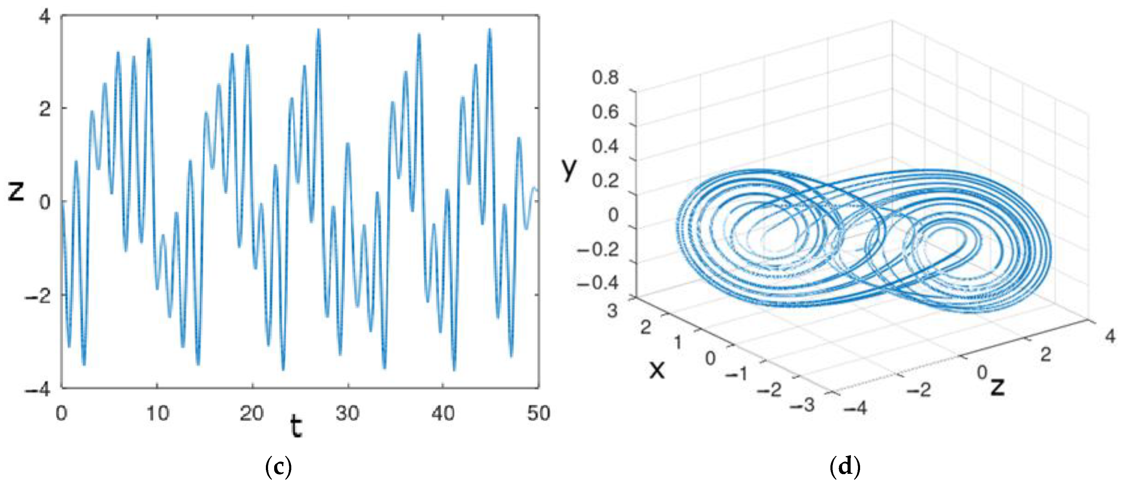
Figure 4a–c shows the graphical representation of the state variables x, y, and z as a function of time, while Figure 4d shows that the trajectory forms an attractor, confirming that it is a chaotic dynamic system.
Now, based on the mathematical model for n identical coupled Chua circuits (Equations (24)–(27)) and by considering the same parameters, solver method, number of steps, and total samples as before, another Octave script was created to simulate 3 Chua circuits synchronized via x state variable. In this case, all initial conditions were set up to 0 except x o of the first circuit that was set up to 0.7. Figure 5 shows the state variables x of the 3 circuits as a function of time. As can be seen, as time progresses, the values of the three variables tend to be the same.

2.6. Hardware-Based Numerical Simulation

The use of FPGAs as a simulation tool is not new and has become popular especially in the study of nonlinear, dynamic, and complex systems. Most of these systems model physical phenomena using ordinary differential equations [29,57,58,59,60,61].
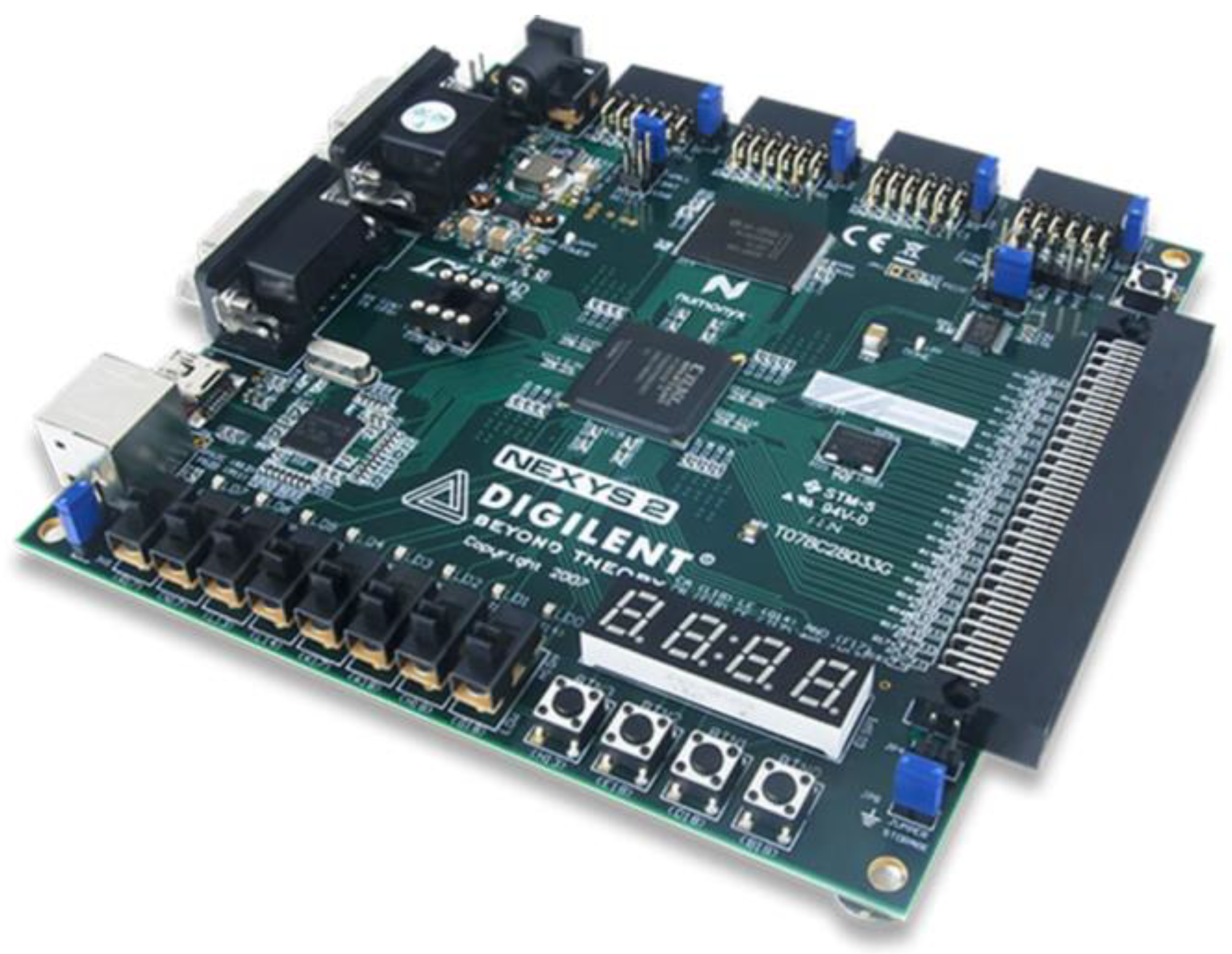
In this work, an FPGA Spartan 3E (Figure 6) was used to carry out the simulation of the Chua circuit and the Chua circuit synchronization. This board integrates a 500k gate XC3S500E FPGA, a 32-bit RISC processor, and a DDR interface, as well as USB ports, ethernet, LCD, potentiometer, switches, serial ports, and JTAG interface. It is fully compatible with Xilinx ISE tools [62].
Like [33], a 32-bit signed number representation fixed-point was used, but in this case, 6 bits for integer part and 25 for the factional one (Table 1).
Figure 7 shows the RTL architecture of the implemented system using Verilog description language. It consists of two main elements: the Chua circuit and a frequency divider.
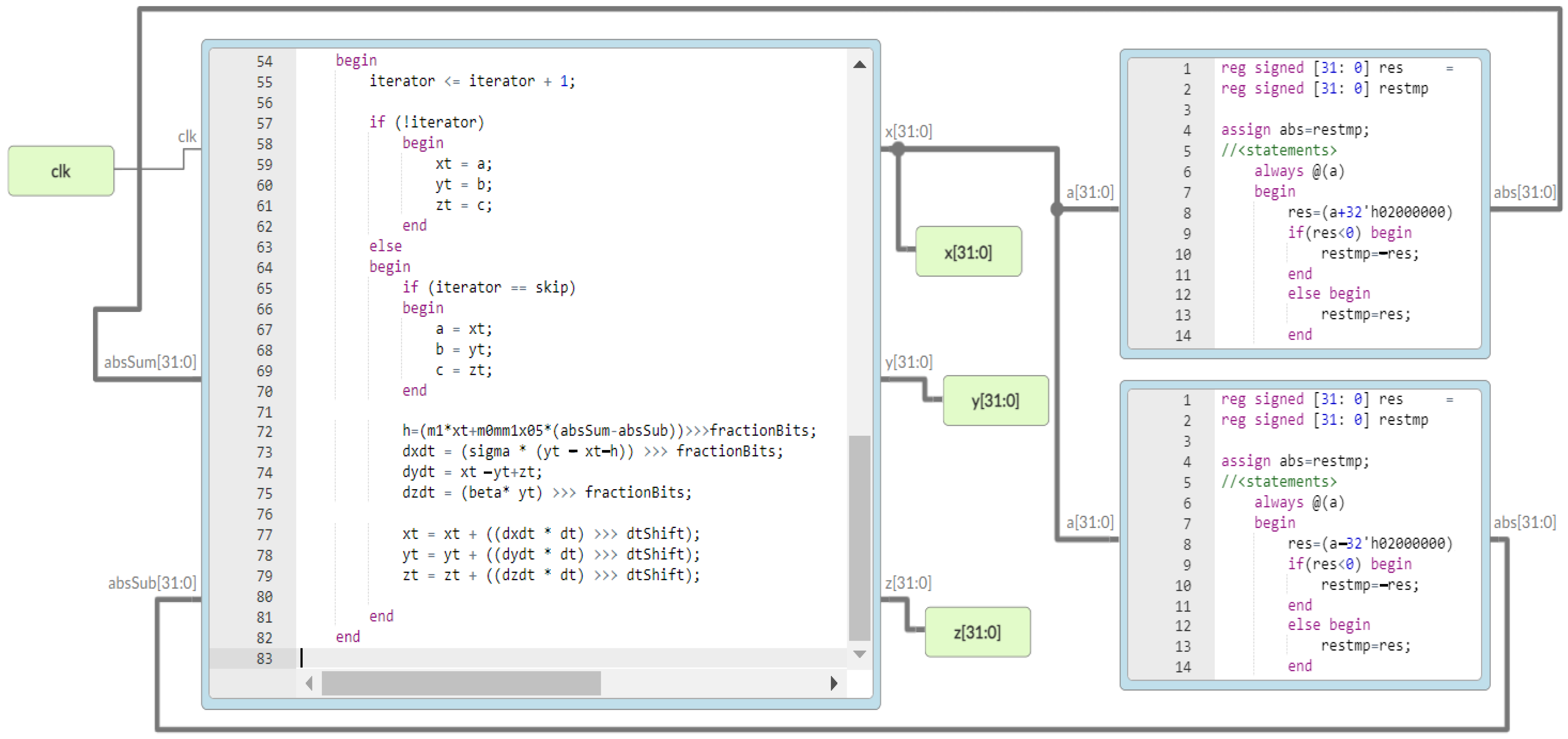
Chua’s circuit solves the x, y, and z equations of state by applying Euler’s method with a step size of 0.005; its Verilog main process and partial RTL are shown in Figure 8.
On the other hand, the frequency divider (Figure 9) activates its output when a total of 10,000 samples have been processed. The system frequency is 50 Mhz.
In Figure 10, the behavior of the state variables x, y, and z with respect to time can be visualized; its behavior is similar to that of a chaotic dynamic circuit.
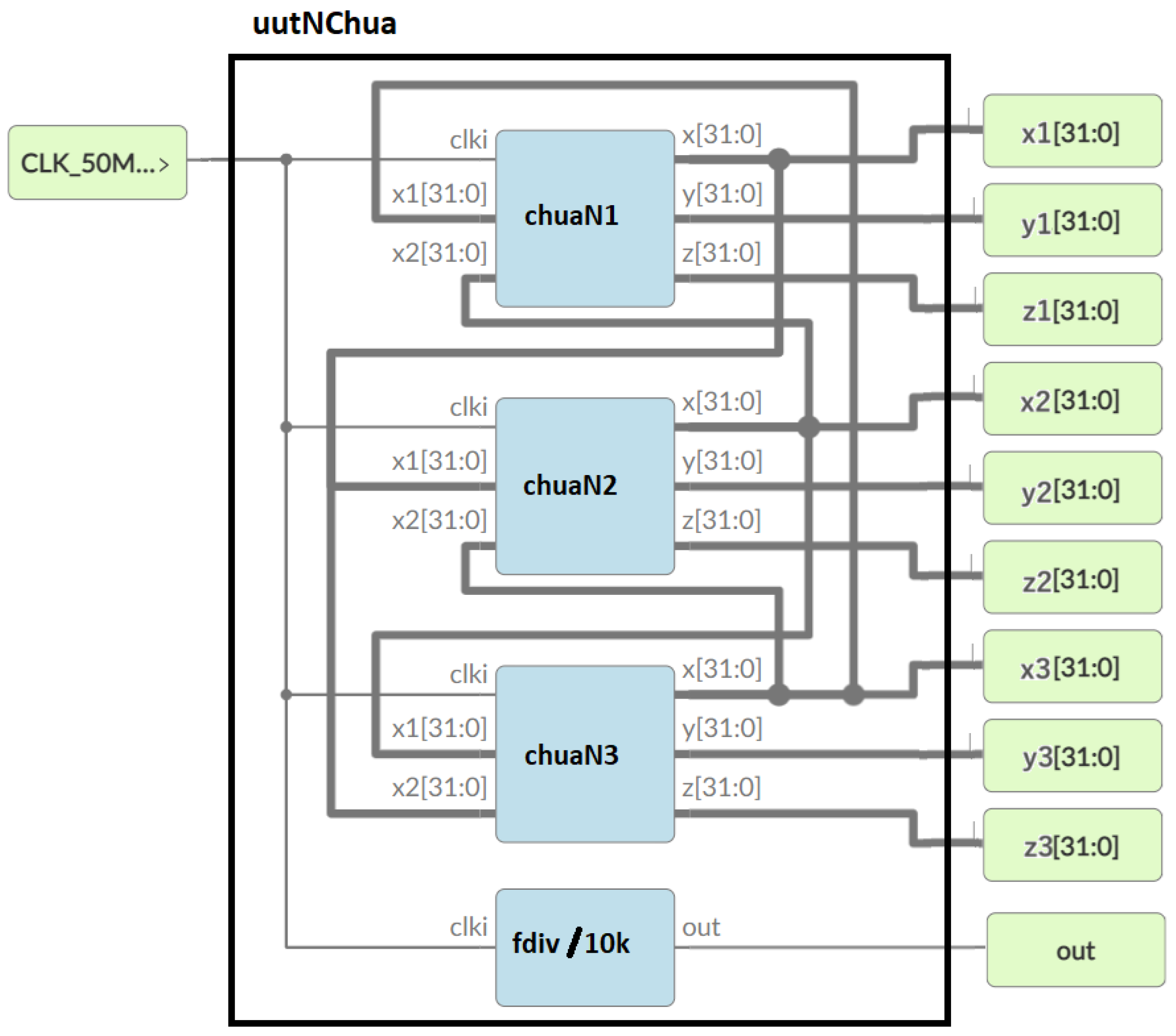
Likewise, Figure 11 shows the RTL architecture created in the FPGA for three nodes synchronized with each other. It consists of four main elements, three Chua circuits and a frequency divider.
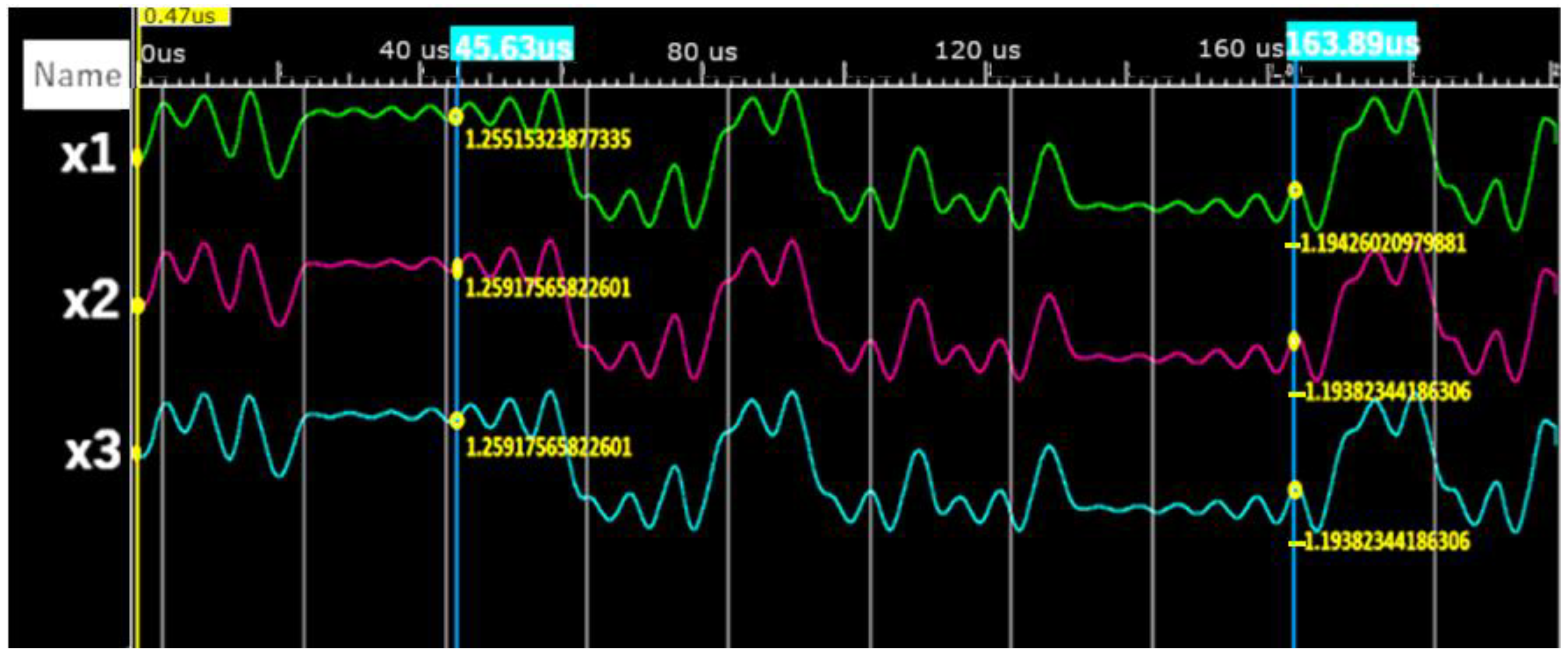
The three Chua circuits are similar to Figure 12 and solve the x, y, and z state equations at the same time, applying Euler’s method with a step size of 0.005, while the frequency divider also activates its output when a total of 10,000 samples have been processed. It uses the same frequency mentioned above.
Figure 13 shows the behavior of the state variables x1, x2, and x3 corresponding to circuits 1, 2, and 3 as a function of time, respectively. In the same way, values tend to be synchronized as time progresses.
Finally, Table 2 shows the percentage of resources used in the FPGA after the synthesis and implementation of three Chua circuits; they do not exceed 4% of the total.

3. Results

In this section, the results obtained after implementing the Chua circuit in the FPGA are presented and compared with the results obtained using the octave numerical simulation software for three couple Chua circuits. Figure 14a–c show the temporal behavior of the state variables obtained using the FPGA ( x f , y f , z f ) and the calculation software ( x , y , z ) for the first Chua circuit. Graphically, it can be seen that there are no significant differences between the calculations made with the software and the electronic device.
Additionally, an analysis of the relationship between the data obtained through the FPGA and the simulation software was carried out. Figure 15 shows a linear relationship between the variables x and x f corresponding to the simulation software and the FPGA, respectively.
As can be seen in Table 3, the Pearson correlation coefficient is 1 or very close to 1, which categorically indicates that the variables are highly related.
Finally, the simulation times of a Chua circuit and three synchronized Chua circuits were determined. The results obtained with the software and with the FPGA for 10,000 samples are shown in Table 4. As can be seen, with the use of hardware, the simulation time can be significantly reduced regardless of the number of circuits to be simulated.

4. Conclusions

In this work, the development of a numerical simulator based on FPGA was proposed, significantly contributing to the field of efficient hardware-based simulation of chaotic systems. Using the Verilog language, an ODE solver was created to solve the state equations of a Chua circuit and three synchronized Chua circuits. The system was synthesized on a Spartan 3E FPGA and used less than 4% of the available resources, demonstrating its resource efficiency. The results were compared with those obtained using Octave numerical calculation software. The proposed system achieved a simulation time of 0.2 ms for one and three circuits with 10,000 samples, whereas the software took 493 ms and 3.1717 s for one and three circuits, respectively. This substantial improvement in simulation speed highlights the effectiveness of the FPGA-based approach in handling complex simulations more efficiently than traditional software methods. It is also confirmed that the simulation time using the software increases with the number of circuits, while for the simulator using the FPGA, it remains the same regardless of the number of simulated circuits, being limited only to the FPGA resources.

Author Contributions

Conceptualization, L.R. and M.M.; methodology, M.M., K.T. and L.R.; validation, R.D., W.R. and M.M.; formal analysis, L.R., M.M. and K.T.; investigation, R.D., M.M. and L.R.; writing—original draft preparation, M.M. and L.R.; writing—review and editing, W.R., M.M., R.D. and L.R.; visualization, R.A., M.M. and W.R.; supervision, M.M. and L.R. All authors have read and agreed to the published version of the manuscript.

Funding

Thanks to the Technical University of Ambato, to the Research and Development (DIDE-UTA), and the research group GESTIÓN DE RECURSOS NATURALES E INFRAESTRUCTURAS SUSTENTABLE (GeReNIS) for supporting our research.

Data Availability Statement

The data presented in this study are available upon request from the corresponding author.

Conflicts of Interest

The authors declare no conflict of interest.

Appendix A

Chua circuit complete Verilog script.
//‘timescale <time_units> / <precision>
module chua (clk,x, y, z);
parameter integerBits= 6;
  parameter fractionBits=25 ;
  parameter dtBits=16 ;
  parameter dtShift=30 ;
  parameter iteratorBits=16 ;
  parameter signed [integerBits + fractionBits : 0 ] dt=0.005 *(2.0 ** (fractionBits));
  parameter  [iteratorBits - 1 : 0 ] skip=1024 ;
  parameter signed [integerBits + fractionBits : 0 ] sigma=15.0 * 1 *(2.0 **(fractionBits));
  parameter signed [integerBits + fractionBits : 0 ] rho=1.0 * 1 *(2.0 ** (fractionBits));
  parameter signed [integerBits + fractionBits : 0 ] beta =28.0 * 1 *(2.0 ** (fractionBits));
  parameter signed [integerBits + fractionBits : 0 ] m1=-0.714 * 1 *(2.0 ** (fractionBits));
  parameter signed [integerBits + fractionBits : 0 ] m0mm1x05=-0.2145 *1 * (2.0 ** (fractionBits));
  parameter signed [integerBits + fractionBits : 0 ] startX=0.7 * 1 *(2.0 ** fractionBits);
  parameter signed [integerBits + fractionBits : 0 ] startY=0.0 * 1 *(4.0 ** fractionBits);
  parameter signed [integerBits + fractionBits : 0 ] startZ=0.0 * 1 *(2.0 ** fractionBits);
  localparam totalBits = 1 + integerBits + fractionBits;
  input  wire clk;
  output reg  signed [totalBits-1 :0 ] x = startX;
  output reg  signed [totalBits-1 :0 ] y = startY;
  output reg  signed [totalBits-1 :0 ] z = startZ;
  reg  [iteratorBits-1 :0 ] iterator = 0 ;
  reg signed [totalBits-1 :0 ] a = startX;
  reg signed [totalBits-1 : 0 ] b = startY;
  reg signed [totalBits -1 :0 ] c = startZ;
  reg signed [totalBits*2 -1 :0 ] h = 0 ;
  reg signed [totalBits-1 :0 ] abs1 = 0 ;
  reg  signed [totalBits-1 :0 ] abs2 = 0 ;
  reg signed [totalBits*2 -1 :0 ] dxdt = 0 ;
  reg signed [totalBits*2 -1 :0 ] dydt = 0 ;
  reg signed [totalBits*2 -1 :0 ] dzdt = 0 ;
  reg signed [totalBits - 1 : 0 ] res = 0 ;
  always @(posedge clk)
  begin
    iterator <= iterator+1 ;
    if (!iterator)
       begin
        x = a;
        y = b;
        z = c;
      end
    else
    begin
      if (iterator == skip)
      Begin
        a = x;
        b = y;
        c = z;
      End
abs1=x+32 h04000000 ;
if (abs1<0 ) begin
abs1=-abs1;
end
abs2=(x-32 h04000000 );
if (abs2<0begin
abs2=-abs2;
end
      h=(m1*x+m0mm1x05*(abs1-abs2))>>>fractionBits;
      dxdt = (sigma * (y - x-h)) >>> fractionBits;
       dydt = x -y+z;
      dzdt = (-beta* y) >>> fractionBits;
      x = x + ((dxdt * dt) >>> fractionBits);
      y = y + ((dydt * dt) >>> fractionBits);
      z = z + ((dzdt * dt) >>> fractionBits);
    end
  end
endmodule

Appendix B

Synchronized Chua circuit complete Verilog script.
‘timescale 1ns / 1ps
module chuaN(clk,x1,x2,x,y,z);
  parameter integerBits = 6;
  parameter fractionBits = 25;
  parameter dtBits = 16;
  parameter dtShift = 30;
  parameter iteratorBits = 16;
  parameter signed [integerBits + fractionBits : 0] dt=0.0005 *(2.0 ** (fractionBits));
  parameter  [iteratorBits - 1:0] skip = 1024;
  parameter signed [integerBits + fractionBits:0] sigma = 15.0 * 1*(2.0 ** (fractionBits));
  parameter signed [integerBits + fractionBits : 0] rho = 1.0 * 1*(2.0 ** (fractionBits));
  parameter signed [integerBits + fractionBits : 0] beta = 28.0 * 1*(2.0 ** (fractionBits));
  parameter signed [integerBits + fractionBits : 0] m1 = -0.714 * 1*(2.0 ** (fractionBits));
  parameter signed [integerBits + fractionBits : 0] m0mm1x05 = -0.2145 *1* (2.0 ** (fractionBits));
  parameter signed [integerBits + fractionBits : 0] startX = 0.7 * 1*(2.0 ** fractionBits);
  parameter signed [integerBits + fractionBits : 0] startY = 0.0 * 1*(2.0 ** fractionBits);
  parameter signed [integerBits + fractionBits : 0] startZ = 0.0 * 1*(2.0 ** fractionBits);
  parameter signed [integerBits + fractionBits : 0] deltaX = 7 * (2.0 ** (fractionBits));
parameter signed [integerBits + fractionBits : 0] uno = 1 * (2.0 ** (fractionBits));
  localparam totalBits = 1 + integerBits + fractionBits;
  input  wire clk;
  input  signed [totalBits – 1 : 0] x2;
  input  signed [totalBits – 1 :0] x1;
  output reg  signed [totalBits - 1 : 0] x = startX;
  output reg  signed [totalBits - 1 : 0] y = startY;
  output reg  signed [totalBits - 1 : 0] z = startZ;
  reg    [iteratorBits - 1 : 0] iterator = 0;
  reg signed [totalBits - 1 : 0] a = startX;
  reg signed [totalBits - 1 : 0] b = startY;
  reg signed [totalBits - 1 : 0] c = startZ;
  reg signed [totalBits * 2 - 1 : 0] h = 0;
  reg signed [totalBits - 1 : 0] abs1 = 0;
  reg  signed [totalBits - 1 : 0] abs2 = 0;
  reg signed [totalBits * 2 - 1 : 0] dxdt = 0;
  reg signed [totalBits * 2 - 1 : 0] dydt = 0;
  reg signed [totalBits * 2 - 1 : 0] dzdt = 0;
  reg signed [totalBits - 1 : 0] res = 0;
  always @(posedge clk)
  begin
    iterator <= iterator + 1;
    if (!iterator)
      begin
        x = a;
        y = b;
        z = c;
      end
    else
    begin
      if (iterator == skip)
      begin
        a = x;
        b = y;
        c = z;
      end
 abs1=x+uno;
if(abs1<0) begin
abs1=-abs1;
end
 abs2=(x-uno);
if(abs2<0) begin
abs2=-abs2;
end
      h=(m1*x+m0mm1x05*(abs1-abs2))>>>fractionBits;
    dxdt = (sigma * (y - x-h)-deltaX*(2*x-x1-x2)) >>> fractionBits;
      dydt = x -y+z;
      dzdt = (-beta* y) >>> fractionBits;
      x = x + ((dxdt * dt) >>> fractionBits);
      y = y + ((dydt * dt) >>> fractionBits);
      z = z + ((dzdt * dt) >>> fractionBits);
    end
  end
endmodule

References

  1. Sussman, G.J.; Wisdom, J. Chaotic Evolution of the Solar System. Science 1992, 257, 56–62. [Google Scholar] [CrossRef]
  2. Tél, T.; Gruiz, M.; Kulacsy, K. Chaotic dynamics: An introduction based on classical mechanics. In Chaotic Dynamics: An Introduction Based on Classical Mechanics; Cambridge University Press: Cambridge, UK, 2006; pp. 1–408. ISBN 9780521839129. [Google Scholar] [CrossRef]
  3. Azar, A.T.; Vaidyanathan, S. (Eds.) Advances in Chaos Theory and Intelligent Control; Springer: Berlin/Heidelberg, Germany, 2016; Volume 337. [Google Scholar] [CrossRef]
  4. Zhang, L.; Zhang, C. Chaos Control in a Discrete Ecological System. Int. J. Mod. Nonlinear Theory Appl. 2012, 1, 81–83. [Google Scholar] [CrossRef]
  5. Wang, Y.; Yin, X.; Liu, Y. Control Chaos in System with Fractional Order. J. Mod. Phys. 2012, 3, 496–501. [Google Scholar] [CrossRef]
  6. Oestreicher, C. A history of chaos theory. Dialog-Clin. Neurosci. 2022, 9, 279–289. [Google Scholar] [CrossRef] [PubMed]
  7. Nicolis, J.S. Chaotic dynamics applied to information processing. Rep. Prog. Phys. 1986, 49, 1109–1196. [Google Scholar] [CrossRef]
  8. Eroglu, D.; Lamb, J.S.W.; Pereira, T. Synchronisation of chaos and its applications. Contemp. Physics 2017, 58, 207–243. [Google Scholar] [CrossRef]
  9. Li, P.; Shi, S.; Xu, C.; Rahman, M.U. Bifurcations, chaotic behavior, sensitivity analysis and new optical solitons solutions of Sasa-Satsuma equation. In Nonlinear Dynamics; Springer: Berlin/Heidelberg, Germany, 2024; Volume 112, pp. 7405–7415. [Google Scholar] [CrossRef]
  10. Kuznetsov, N.; Mokaev, T.; Ponomarenko, V.; Seleznev, E.; Stankevich, N.; Chua, L. Hidden attractors in Chua circuit: Mathematical theory meets physical experiments. Nonlinear Dyn. 2023, 111, 5859–5887. [Google Scholar] [CrossRef]
  11. Abdulaali, R.S.; Jamal, R.K. A Comprehensive Study and Analysis of the Chaotic Chua Circuit. Iraqi J. Sci. 2022, 63, 556–570. [Google Scholar] [CrossRef]
  12. Lv, E. Chua’s Circuit Simulation Experiment Based on Saturation Function. J. Phys. Conf. Ser. 2021, 2078, 012026. [Google Scholar] [CrossRef]
  13. Suxo-Coro, A.A.; Callejas-Icuña, A.S.; Nina, C.; Medrano-Torricos, R.O.; Ramírez-Ávila, G.M. Dinámica de circuitos de Chua con bobinas no ideales e histéresis. Rev. Boliv. Física 2022, 40, 13–25. Available online: http://www.scielo.org.bo/scielo.php?script=sci_arttext&pid=S1562-38232022000100004&lng=es&nrm=iso&tlng=es (accessed on 30 May 2023). [CrossRef]
  14. Montalvo, R.A.; Rivera, P.H. Experimentando el circuito de Chua. Rev. Boliv. Física 2017, 19, 161902752. [Google Scholar] [CrossRef]
  15. Tsafack, N.; Kengne, J. Complex Dynamics of the Chua’s Circuit System with Adjustable Symmetry and Nonlinearity: Multistability and Simple Circuit Realization. World J. Appl. Phys. 2019, 4, 24. [Google Scholar] [CrossRef]
  16. Kheir, N.A. Systems Modeling and Computer Simulation; Dekker, M., Ed.; Routledge: London, UK, 1996; Available online: https://www.routledge.com/Systems-Modeling-and-Computer-Simulation/Kheir/p/book/9780824794217 (accessed on 4 June 2023).
  17. Yang, T.; Chua, L.O. Secure communication via chaotic parameter modulation. In IEEE Transactions on Circuits and Systems I: Fundamental Theory; IEEE: New York, NY, USA, 1996; Available online: https://ieeexplore.ieee.org/abstract/document/536758/ (accessed on 29 July 2024).
  18. Kennedy, M.P. Three Steps to Chaos—Part II: A Chua’s Circuit Primer. IEEE Trans. Circuits Syst. I Fundam. Theory Appl. 1993, 40, 657–674. [Google Scholar] [CrossRef]
  19. Caponetto, R.; Criscione, M.; Fortuna, L.; Occhipinti, D.; Occhipinti, L. Programmable chaos generator, based on CNN architectures, with applications in chaotic communications. In Proceedings of the IEEE International Workshop on Cellular Neural Networks and Their Applications, London, UK, 14–17 April 1998; pp. 124–129. [Google Scholar] [CrossRef]
  20. Pecora, L.M.; Carroll, T.L. Synchronization in chaotic systems. Phys. Rev. Lett. 1990, 64, 821–824. [Google Scholar] [CrossRef] [PubMed]
  21. Zhong, G.-Q.; Ayrom, F. Experimental confirmation of chaos from Chua’s circuit. Int. J. Circuit Theory Appl. 1985, 13, 93–98. [Google Scholar] [CrossRef]
  22. García-García, J.A.; Enríquez, J.G.; Ruiz, M.; Arévalo, C.; Jiménez-Ramírez, A. Software Process Simulation Modeling: Systematic literature review. Comput. Stand Interfaces 2020, 70, 103425. [Google Scholar] [CrossRef]
  23. Boghosian, B.M.; Coveney, P.V.; Wang, H.; Boghosian, B.M.; Wang, H.; Coveney, V. A New Pathology in the Simulation of Chaotic Dynamical Systems on Digital Computers. Adv. Theory Simul. 2019, 2, 1900125. [Google Scholar] [CrossRef]
  24. Hussain, H.M.; Benkrid, K.; Seker, H.; Erdogan, A.T. FPGA implementation of K-means algorithm for bioinformatics application: An accelerated approach to clustering Microarray data. In Proceedings of the 2011 NASA/ESA Conference on Adaptive Hardware and Systems, AHS 2011, San Diego, CA, USA, 6–9 June 2011; pp. 248–255. [Google Scholar] [CrossRef]
  25. Wang, Y.; Ribeiro, J.M.L.; Tiwary, P. Machine learning approaches for analyzing and enhancing molecular dynamics simulations. Curr. Opin. Struct. Biol. 2020, 61, 139–145. [Google Scholar] [CrossRef]
  26. Duncan, A.L.; Pezeshkian, W. Mesoscale simulations: An indispensable approach to understand biomembranes. Biophys. J. 2023, 122, 1883–1889. [Google Scholar] [CrossRef]
  27. Ooms, J.; Hübl, A. Applying a Hybrid Model to Solve the Job-Shop Scheduling Problem with Preventive Maintenance, Sequence-Dependent Setup Times and Unknown Processing Times. In Proceedings of the 2022 Winter Simulation Conference (WSC), Singapore, 11–14 December 2022; Volume 2022, pp. 1750–1761. [Google Scholar] [CrossRef]
  28. Le-Huy, P.; Guérette, S.; Dessaint, L.A.; Le-Huy, H. Real-time simulation of power electronics in power systems using an FPGA. In Proceedings of the Canadian Conference on Electrical and Computer Engineering, Ottawa, ON, Canada, 7–10 May 2006; pp. 873–877. [Google Scholar] [CrossRef]
  29. Borgese, G.; Pace, C.; Pantano, P.; Bilotta, E. FPGA-based distributed computing microarchitecture for complex physical dynamics investigation. IEEE Trans. Neural Netw. Learn Syst. 2013, 24, 1390–1399. [Google Scholar] [CrossRef]
  30. Matar, M.; Abdel-Rahman, M.; Soliman, A.-M. FPGA-Based Real-Time Digital Simulation. In Proceedings of the International Conference on Power Systems Transients (IPST’05) in Montreal, Montreal, QC, Canada, 19–23 June 2015. [Google Scholar]
  31. Chen, H.; Sun, S.; Aliprantis, D.C.; Zambreno, J. Dynamic Simulation of Electric Machines on FPGA Boards. In Proceedings of the 2009 IEEE International Electric Machines and Drives Conference (IEMDC), Miami, FL, USA, 3–6 May 2009. [Google Scholar]
  32. Watanabe, H.; Matsutani, H. Accelerating ode-based neural networks on low-cost FPGAs a preprint. arXiv 2023, arXiv:2012.15465. [Google Scholar]
  33. Mayacela, M.; Rentería, L.; Contreras, L.; Medina, S. Comparative Analysis of Reconfigurable Platforms for Memristor Emulation. Materials 2022, 15, 4487. [Google Scholar] [CrossRef] [PubMed]
  34. Mamat, M.; Sanjaya, M.; Maulana, D.S. Numerical Simulation Chaotic Synchronization of Chua Circuit and Its Application for Secure Communication. Appl. Math. Sci. 2013, 7, 1–10. [Google Scholar] [CrossRef]
  35. Muni, S.S.; Provata, A. Chimera states in ring–star network of Chua circuits. Nonlinear Dyn. 2020, 101, 2509–2521. [Google Scholar] [CrossRef]
  36. Zhou, P.; Ma, J.; Xu, Y. Phase synchronization between neurons under nonlinear coupling via hybrid synapse. Chaos Solitons Fractals 2023, 169, 113238. [Google Scholar] [CrossRef]
  37. Liu, Z.; Ma, J.; Zhang, G.; Zhang, Y. Synchronization control between two Chua′s circuits via capacitive coupling. Appl. Math. Comput. 2019, 360, 94–106. [Google Scholar] [CrossRef]
  38. Pivka, L.; Wu, C.; Huang, A. Chua’s oscillator: A compendium of chaotic phenomena. In Journal of the Franklin Institute; Elsevier: Amsterdam, The Netherlands, 1994; Available online: https://www.sciencedirect.com/science/article/pii/0016003294900876 (accessed on 18 June 2023).
  39. Chen, C.; Ma, H.; Chen, H.; Meng, Y.; Ding, Q. FPGA implementation of a UPT chaotic signal generator for image encryption. Pac. Sci. Rev. A Nat. Sci. Eng. 2015, 17, 97–102. [Google Scholar] [CrossRef]
  40. Chua, L.O.; Itoh, M.; Kocarev, L.; Eckert, K. Chaos synchronization in chua’s circuit. J. Circuits Syst. Comput. 2011, 3, 93–108. [Google Scholar] [CrossRef]
  41. Yao, Z.; Ma, J.; Yao, Y.; Wang, C. Synchronization realization between two nonlinear circuits via an in-duction coil coupling. Nonlinear Dyn. 2019, 96, 205–217. [Google Scholar] [CrossRef]
  42. Youssef, T.; Chadli, M.; Karimi, H.R.; Zelmat, M. Chaos synchronization based on unknown input proportional multiple-integral fuzzy observer. In Abstract and Applied Analysis; Hindawi Publishing Corporation: New York, NY, USA, 2013; Volume 2013. [Google Scholar] [CrossRef]
  43. Coddington, E.A.; Levinson, N. Theory of Ordinary Differential Equations; McGraw-Hill Book Company, Inc.: New York, NY, USA, 1991; p. 429. Available online: https://books.google.com/books/about/Theory_of_Ordinary_Differential_Equation.html?hl=es&id=bPJQAAAAMAAJ (accessed on 30 July 2024).
  44. Sun, J.; Shen, Y.; Yin, Q.; Xu, C. Compound synchronization of four memristor chaotic oscillator systems and secure communication. Chaos 2013, 23, 013140. [Google Scholar] [CrossRef]
  45. Wu, C.W.; Chua, L.O. A simple way to synchronize chaotic systems with applica-tions to secure communication systems. Int. J. Bifurc. Chaos 1993, 3, 1619–1627. [Google Scholar] [CrossRef]
  46. Diaconu, A.; Loukhaoukha, K. An Improved Secure Image Encryption Algorithm Based on Rubik’s Cube Principle and Digital Chaotic Cipher. Available online: https://www.hindawi.com/journals/mpe/2013/848392/ (accessed on 19 June 2023).
  47. Mosekilde, E.; Maistrenko, Y.; Postnov, D. Chaotic Synchronization: Applications to Living Systems. 2002. Available online: https://books.google.com/books?hl=es&lr=&id=6YZ2gEv5qsQC&oi=fnd&pg=PA1&dq=Chaotic+Synchronization:+Applications+to+Living+Systems&ots=ixRn6Au2C_&sig=NhlldTQYOB_BfEFOcBThli4LR44 (accessed on 19 June 2023).
  48. Yu, Y.; Zhang, S. The synchronization of linearly bidirectional coupled chaotic systems. Chaos Solitons Fractals 2004, 22, 189–197. [Google Scholar] [CrossRef]
  49. Jiang, G.P.; Tang, W.K.S.; Chen, G. A simple global synchronization criterion for coupled chaotic systems. Chaos Solitons Fractals 2003, 15, 925–935. [Google Scholar] [CrossRef]
  50. Boccaletti, S.; Kurths, J.; Osipov, G.; Valladares, D.L.; Zhou, C.S. The synchronization of chaotic systems. Phys. Rep. 2002, 366, 1–101. [Google Scholar] [CrossRef]
  51. Jiang, C.; Zada, A.; Şenel, M.T.; Li, T. Synchronization of bidirectional N-coupled fractional-order chaotic systems with ring connection based on antisymmetric structure. Adv. Differ. Equ. 2019, 2019, 456. [Google Scholar] [CrossRef]
  52. Sanjaya, W.S.M.; Anggraeni, D.; Denya, R.; Ismail, N. Numerical Simulation Bidirectional Chaotic Syn-chronization of Spiegel-Moore Circuit and Its Application for Secure Communication. IOP Conf. Ser. Mater. Sci. Eng. 2017, 180, 012066. [Google Scholar] [CrossRef]
  53. Pecora, L.M.; Carroll, T.L. Synchronization of chaotic systems. Chaos 2015, 25, 97611. [Google Scholar] [CrossRef]
  54. Proakis, J.G.; Manolakis, D.G. Digital Signal Processing: Principles, Algorithms, and Applications; Pearson Education India: Delhi, India, 1996. [Google Scholar]
  55. Meyer-Baese, U.; Meyer-Baese, U. Digital Signal Processing with Field Programmable Gate Arrays. 2007. Available online: https://link.springer.com/content/pdf/10.1007/978-3-642-45309-0.pdf (accessed on 28 July 2024).
  56. Atkinson, K.E. An Introduction to Numerical Analysis; John Wiley & Sons: Hoboken, NJ, USA, 1989. [Google Scholar]
  57. Koutroulis, E.; Kalaitzakis, K.; Tzitzilonis, V. Development of an FPGA-based system for real-time simulation of photovoltaic modules. Microelectron. J 2009, 40, 1094–1102. [Google Scholar] [CrossRef]
  58. Saad, H.; Ould-Bachir, T.; Mahseredjian, J.; Dufour, C.; Dennetiere, S.; Nguefeu, S. Real-time simulation of MMCs using CPU and FPGA. IEEE Trans. Power Electron. 2015, 30, 259–267. [Google Scholar] [CrossRef]
  59. Mahmoodi, D.; Soleimani, A.; Khosravi, H.; Taghizadeh, M. FPGA Simulation of Linear and Nonlinear Support Vector Machine. J. Softw. Eng. Appl. 2011, 4, 320–328. [Google Scholar] [CrossRef]
  60. Chiou, D.; Sunwoo, D.; Kim, J.; Patil, N.A.; Reinhart, W.; Johnson, D.E.; Keefe, J.; Angepat, H. FPGA-accelerated simulation technologies (FAST): Fast, full-system, cycle-accurate simula-tors. In Proceedings of the Annual International Symposium on Microarchitecture, MICRO, Chicago, IL, USA, 1–5 December 2007; pp. 249–261. [Google Scholar] [CrossRef]
  61. Huang, C.; Vahid, F.; Givargis, T. A custom FPGA processor for physical model ordinary differential equation solving. IEEE Embed. Syst. Lett. 2011, 3, 113–116. [Google Scholar] [CrossRef]
  62. Popescu, S.O.; Gontean, A.S.; Budura, G. BPSK system on Spartan 3E FPGA. In Proceedings of the IEEE 10th Jubilee Interna-tional Symposium on Applied Machine Intelligence and Informatics, SAMI 2012, Herl’any, Slovakia, 26–28 January 2012; pp. 301–306. [Google Scholar] [CrossRef]
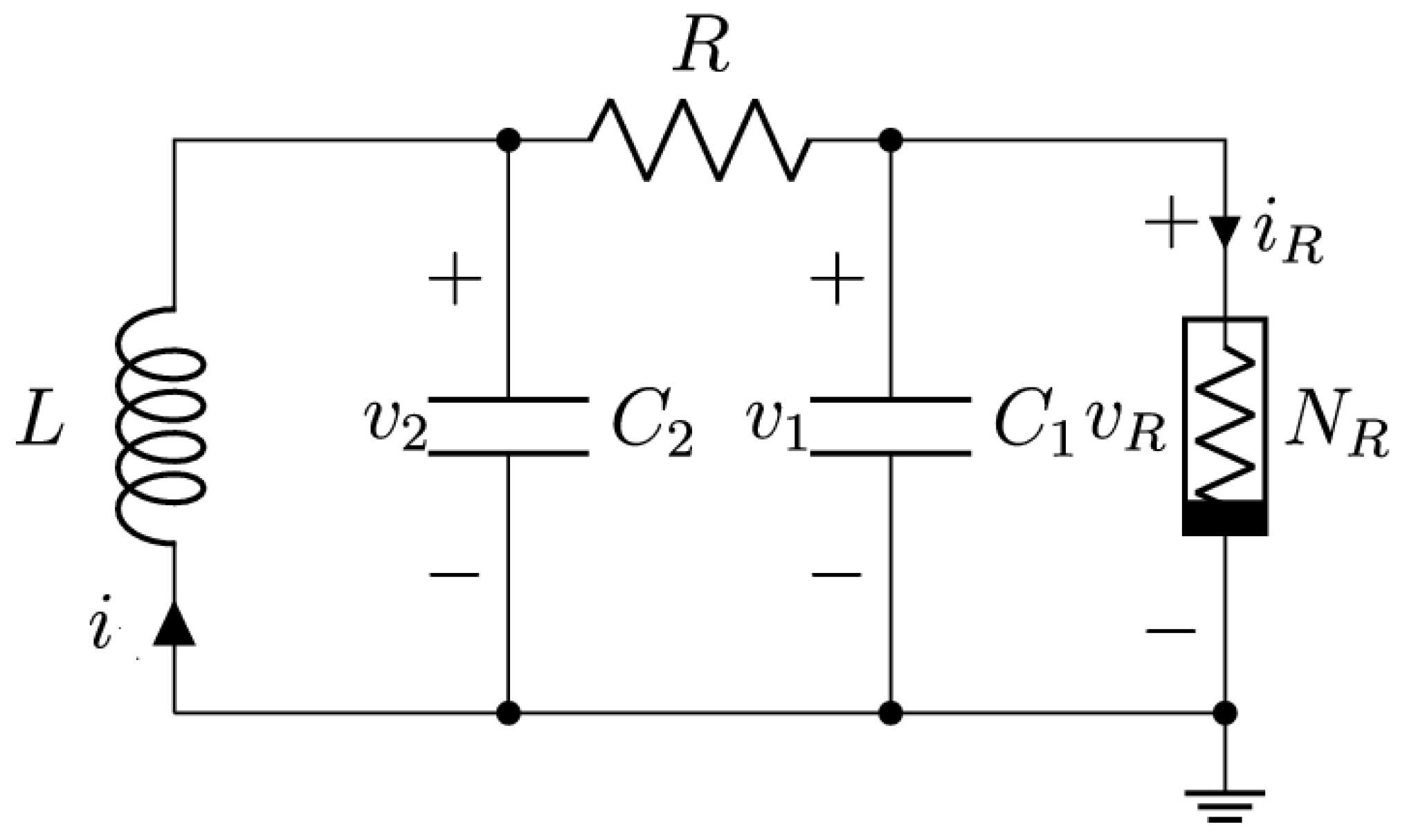
Figure 1. Chua circuit.
Computation 12 00174 g001
Figure 2. The coupled mode of 2 identical Chua circuits via bidirectional coupling.
Computation 12 00174 g002
Figure 3. The coupled mode of n identical Chua circuits via bidirectional coupling.
Computation 12 00174 g003
Figure 4. State variables as a function of time under the following parameters: x 0 = 0.7 , y 0 = 0.0 ,   z 0 = 0.0 ,   = 15.6 , β = 28 , m 0 = 1.143 , m 1 = 0.714 : (a) x vs. t; (b) y vs. t; (c) z vs. t and (d) 3D projection of the attractor.
Computation 12 00174 g004aComputation 12 00174 g004b
Figure 5. State variables x of 3 coupled Chua circuits as a function of time under the following parameters:   = 15.6 , β = 28 , m 0 = 1.143 , m 1 = 0.714 , and for the first circuit x 0 = 0.7 . The initial conditions of all other state variables were set up to 0.
Computation 12 00174 g005
Figure 6. Spartan 3E FPGA development board.
Computation 12 00174 g006
Figure 7. Register-transfer level (RTL) of one Chua circuit. All constants and parameters are the same as in the simulation.
Computation 12 00174 g007
Figure 8. Chua Circuit Verilog main process and partial RTL, absSum, and absSub blocks used for h function. Complete code is in Appendix A.
Computation 12 00174 g008
Figure 9. Frequency divider Verilog main process and RTL.
Computation 12 00174 g009
Figure 10. FPGA-based Chua circuit state variables x, y, and z as a function of the time.
Computation 12 00174 g010
Figure 11. Register-transfer level (RTL) of 3 coupled Chua circuits. All constants and parameters are the same as in the simulation.
Computation 12 00174 g011
Figure 12. Synchronized Chua Circuit Verilog main process and partial RTL. Complete code is in Appendix B.
Computation 12 00174 g012
Figure 13. FPGA-based coupled Chua circuits state variables x1, x2, and x3 as a function of the time.
Computation 12 00174 g013
Figure 14. Octave state variables x 1 , y 1 , z 1 , and FPGA-based Chua circuit state variables x 1 f , y 1 f , and z 1 f as a function of the time of the first coupled Chua circuit: (a) x 1   &   x 1 f v s . t , (b) y 1   &   y 1 f   v s . t , and (c) z 1   &   z 1 f   v s .   t .
Computation 12 00174 g014
Figure 15. Scatter plot of the linear relationship of x 1 vs. x 1 f . x 1 f is the state variable x of FPGA, and x 1 is the state variable x of the software.
Computation 12 00174 g015
Table 1. Fixed-point 32-bit Q6.25 number representation.
Number BinaryHexadecimal
1.00_000001.000000000000000000000000002000000
0.00250_000000.000000010100011110101110000028F5C
Table 2. Device utilization resource summary for Chua circuit implementation.
Logic Utilization UsedUtilization
Number of Slice Flip Flop291%
Number of 4 input LUTs161%
Number of occupied Slices251%
Number of bonded IOBs31%
Table 3. Correlation coefficient and linear model of the state variables of the FPGA ( x f , y f , z f   ) and the simulation software ( x , y , z ).
Variable xVariable yrLineal Model
y = mx + b
bm
x 1 f   x 1 1.0−0.000016351.00000263
x 2 f   x 2 1.0−0.000015411.00000245
x 3 f   x 3 1.0−0.000015411.00000245
y 1 f   y 1 0.99998870.000013531.00001967
y 2 f   y 2 0.99994980.000022141.00002846
y 3 f   y 3 0.99994980.000022141.00002846
z 1 f   z 1 0.99997880.00011841.0000158
z 2 f   z 2 0.99999250.000055491.00001217
z 3 f   z 3 0.99999250.000055491.00001217
Table 4. Simulation times for 10,000 samples of a Chua circuit and three synchronized Chua circuits using Octave software V9.1.0 and the FPGA.
ToolNumber of Chua CircuitsSimulation Time
Octave (Intel(R) Core i7-9750H CPU 2.59 GHz computer)1493 ms
33.177 s
FPGA10.2 ms
30.2 ms
Disclaimer/Publisher’s Note: The statements, opinions and data contained in all publications are solely those of the individual author(s) and contributor(s) and not of MDPI and/or the editor(s). MDPI and/or the editor(s) disclaim responsibility for any injury to people or property resulting from any ideas, methods, instructions or products referred to in the content.