Abstract
This study presents a novel encryption method for RGB (Red–Green–Blue) color images that combines scrambling techniques with the logistic map equation. In this method, image scrambling serves as a reversible transformation, rendering the image unintelligible to unauthorized users and thus enhancing security against potential attacks. The proposed encryption scheme, called Bit-Plane Representation of Quantum Images (BRQI), utilizes quantum operations in conjunction with a one-dimensional chaotic system to increase encryption efficiency. The encryption algorithm operates in two phases: first, the quantum image undergoes scrambling through bit-plane manipulation, and second, the scrambled image is mixed with a key image generated using the logistic map. To assess the performance of the algorithm, simulations and analyses were conducted, evaluating parameters such as entropy (a measure of disorder) and correlation coefficients to confirm the effectiveness and robustness of this algorithm in safeguarding and encoding color images. The results show that the proposed quantum color image encryption algorithm surpasses classical methods in terms of security, robustness, and computational complexity.
1. Introduction
Both steganography and cryptography are crucial for information security, yet they serve different functions. Cryptography focuses on obscuring the content of information, ensuring that even if the message is intercepted, it remains unreadable to unauthorized parties. In contrast, steganography aims to hide the existence of the information by embedding it within seemingly innocuous carriers such as images, audio files, or text, making it difficult to detect. Cryptography encrypts messages using algorithms and keys, transforming them into unreadable formats. Despite this, encrypted messages can sometimes reveal signs of their encrypted nature, suggesting the presence of concealed information. Steganography, however, hides the message within a cover medium, such as an image or audio file, without leaving visible traces to those not aware of the technique. For instance, if sensitive data needed to be transmitted securely, cryptography would encrypt the message, resulting in a secure but visibly encrypted output that indicates the presence of sensitive information. Steganography, on the other hand, would embed the message within a harmless image or audio file, making the hidden information nearly impossible to detect without knowledge of the steganographic method [1,2,3,4,5,6]. In encryption, two primary methodologies are utilized: scrambling and replacement. Scrambling involves disrupting the pixel arrangement of the original image using algorithms such as Arnold, Fibonacci, and Hilbert [7,8,9,10,11]. Replacement, on the other hand, focuses on altering pixel values, thereby modifying the statistical properties of the encrypted image. Both methods are crucial for ensuring secure data transmission. In the realm of quantum image processing, preserving information security is of utmost importance. The spatial domain of a quantum image encompasses two key attributes: pixel position and color information [12]. Quantum image representation has advanced over time, with lattice-based qubit representations becoming common. One notable technique is the quantum image representation based on bit-planes, which has garnered attention due to its benefits in encryption and image processing. Several factors contribute to the focus on encryption and image processing within quantum image processing, including the impressive capabilities of quantum coherent states, entanglement, and superposition. These factors significantly enhance the encryption process and boost quantum storage capacity. For an image with a “22n” pixel configuration, such as “2n × 2n”, fewer qubits are required compared to other representations. These include Normal Arbitrary Superposition State (NASS), Flexible Representation of Quantum Images (FRQI), Multi-Channel Quantum Images (MCQI), Quantum Multi-Channel Representation (QMCR), generalized NEQR (GNEQR), and Novel Enhanced Quantum Representation (NEQR). Quantum image processing offers several advantages over classical methods. For instance, quantum Fourier transform and Quantum Discrete Cosine Transform provide enhanced efficiency. Image processing and encryption operations can be simulated on classical computers using linear algebra, complex vectors, and unitary matrices. Quantum states are often described by probability distributions rather than individual states, with measurements producing probability distributions as output. The normalized quantum state of an image captures both color and pixel position, enabling image storage and processing through quantum Fourier transforms for binary images. Feynman’s computational model introduced the concept of quantum image representation through quantum computers. The FRQI model, for instance, provides a quantum representation for images with a specific number of qubits required for grayscale images. Two-dimensional arrays of qubits represent quantum images, illustrating quantum entanglement states. The MCQI model offers a standardized quantum representation for color images of size 2n × 2n with a minimal qubit requirement of 2n + 3. Compared to FRQI, MCQI is more efficient for image processing, storage, and encryption. It supports watermarking algorithms for color images, whereas FRQI is limited to grayscale images. Encoding a 64 × 64 color image in classical systems requires 12,288 bits, but the MCQI model achieves encryption with just 15 qubits, reducing computational complexity and resource usage. Additionally, MCQI enables simultaneous color image data processing with three qubits, simplifying processing and ensuring consistent color handling across the entire image. The NASS quantum image representation allows for processing both color and grayscale images using 2n quantum qubits for a 22n pixel image, with each qubit representing a single bit of image data. The NEQR model enhances the FRQI model by processing and storing individual pixels using qubits in their base state rather than amplitude. It achieves faster quantum image processing by a factor of two and offers a compression rate up to 1.5 times higher than FRQI while preserving image recovery accuracy. This model provides greater flexibility and simplifies complex pixel color analysis. The Quantum Multi-Channel Representation (QMCR) model introduces a new method for representing color images in quantum computing. QMCR uses two entangled qubit sequences to separately encode color data and pixel locations, improving data representation fidelity. It requires 2n + 24 qubits for a 2n × 2n color image, highlighting its enhanced capabilities and finer resolution in quantum environments. The Bit-Plane Representation of Quantum Images (BRQI) has significantly increased storage capacity, with grayscale images benefiting from a factor of “24” and color images from a factor of “218”. Color images, consisting of three-color channels with eight binary bits each, can be decomposed into 24 binary images, known as bit-planes. This information is detailed in Table 1, which also includes the number of qubits required for color and grayscale images [13,14,15,16,17,18,19,20,21,22,23,24,25,26,27,28]. This paper employs the BRQI technique with n + 6 qubits for color image processing. In quantum encryption, key logic gates such as Pauli-X Gates (Bit-Inversion gates) and Swap Gates are used to manipulate qubits, ensuring secure data transmission and retention.

Table 1.
The evaluation of quantum image representations (QIRs) is conducted for an image consisting of 22n pixels.
2. Preliminaries
To start, this section provides a brief review of quantum bits and quantum gates as fundamental concepts in quantum computing as well as the BRQI representation, which is a key component of our proposed scheme.
2.1. Bit and Qubits
Conventional computers process data and perform calculations using a binary system of bits, which can represent either a 1 or a 0. In contrast, quantum computers employ qubits, which have the remarkable capability to exist in both 1 and 0 states at the same time, at least until a measurement is taken, after which their states are determined.
In practice, a qubit is represented by a two-level physical system, such as an electron with a spin of two , and is shown mathematically by a vector within a two-dimensional complex vector space called Hibert space. Basis qubits are shown by and , along with their corresponding dual states:
Generally, a qubit can be in basis states or in a superposition of the basis states, shown as
In this context, and are referred to as probability amplitudes. In this context, the probability of measuring is given by , whereas the probability of measuring is represented by , so
In quantum computation, we are dealing with two-qubit, three-qubit, and multi-qubit systems. For instance, a two-qubit configuration possesses four fundamental computational states, namely , , , and . Therefore, a general form of a two-qubit system can be given by:
Similar to the case of a single qubit, the same principles extend to a two-qubit system:
One of the most important quantum phenomena in the context of quantum computation is quantum entanglement. For an entangled system of two or more particles, the state of one particle instantly influences the state of the other, regardless of the distance separating them. As an example:
In the case of , the state of the first quantum dictates the state of the second quantum: if the first quantum state is in , the second quantum state will also be in ; conversely, if the first quantum state is in , the second quantum state will likewise be in .
2.2. Quantum Gates and Quantum Circuits
Quantum circuits use logic gates to process information, applying logical transformations through unitary transformations of quantum states. These quantum gates can be represented using matrix notation. A quantum logic gate that acts on a single qubit is known as a single quantum gate. When a qubit enters a quantum circuit of a single qubit gate, the output will be , which can be represented in matrix form.
Common examples of single-qubit gates are the identity gate, Pauli gate (X, Y, and Z), Hadamard gate, and rotation gates. The most common single qubit gates are sorted in Table 2.
Table 2.
A compilation of frequently utilized single quantum gates.
For instance, the Hadamard gate (H), which is a two-qubit quantum gate, plays a crucial role in creating a superposition and transforming the input state of a qubit. It takes the initial state of and generates a superposition state that includes both and as follows:
In addition to single-qubit gates, for the aim of quantum computation, two-qubit gates, three-qubit gates, and multi-qubit gates are needed. The most common two-qubit gate is Controlled-NOT (CNOT gate).
In a CNOT gate, the initial qubit functions as a control qubit, while the subsequent qubit, which is influenced by the first, is referred to as the target qubit. When the first qubit is in the state , the second qubit undergoes a reversal, which is shown as:
When the number of control qubits in a CNOT gate is augmented to two, the resulting gate is referred to as a Toffoli gate.
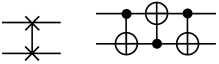
Moreover, the two-qubit SWAP gate facilitates the exchange of two qubits. It enables the swapping of their states, leading to a rearrangement of information or entanglement between the qubits. Additionally, there are two other important gates in quantum computing [13,29]. The most common two-qubit gates are shown in Table 3.
Table 3.
Frequently utilized multiple quantum gates.
3. Our Proposed Model for Quantum Encryption Method for RGB Images Based on Bit-Planes and Logistic Maps
Considering that the model and algorithm presented in the upcoming article are based on the image processing method utilizing bit-planes, this method will first be briefly reviewed. Then, we present our innovative model for quantum RGB image encryption based on bit-planes and logistic maps.
3.1. BRQI for RGB Color Images
To begin with, the bit-plane image processing model should be utilized, which is a modified version of the generalized NEQR (GNEQR) model. The key difference is that we treat each pixel of the image as consisting of bit-planes (8 bits). A grayscale image is composed of 8 binary bits, enabling its decomposition into 8 binary images (or 8 bitmaps), as depicted in Figure 1. Each bitmap derived from a grayscale image can be represented using the GNEQR model in the following manner.
where j denotes the j-th bit-plane, j = 0, 1, …, 7, m = 1, .

Figure 1.
Bit-planes of a grayscale image.
The least significant bit (LSB) of the image depicted in Figure 2 can be preserved:
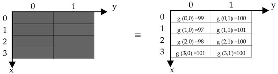
Figure 2.
A 4 × 2 grayscale image.
To depict the eight bit-planes through a state representation, we establish BRQI, which is composed of eight GNEQR states in the (12) configuration.
In the context of the -th bit-plane, where and are defined, it can be inferred from Equation (14) that the BRQI method utilizes merely n + 4 qubits to encode a grayscale image. This represents a 16-fold enhancement in storage capacity when compared to the GNEQR approach outlined in Equation (12).
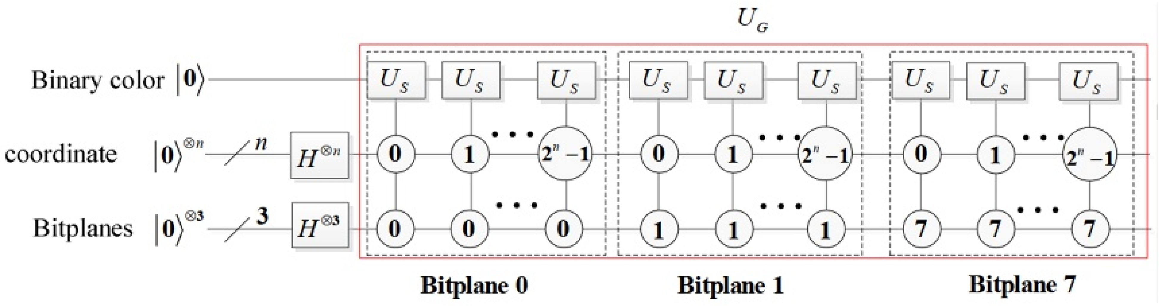
The circuit implementation for BRQI, as detailed in Equation (14), is illustrated in Figure 3, while the corresponding abbreviation circuits are depicted in Figure 4. In Figure 3, the gate is characterized as follows.
The symbol represents an exclusive-or operator. Specifically, if is true, then is applicable; otherwise, is the result.
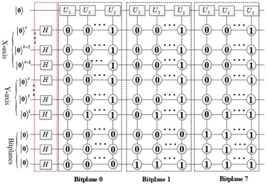
Figure 3.
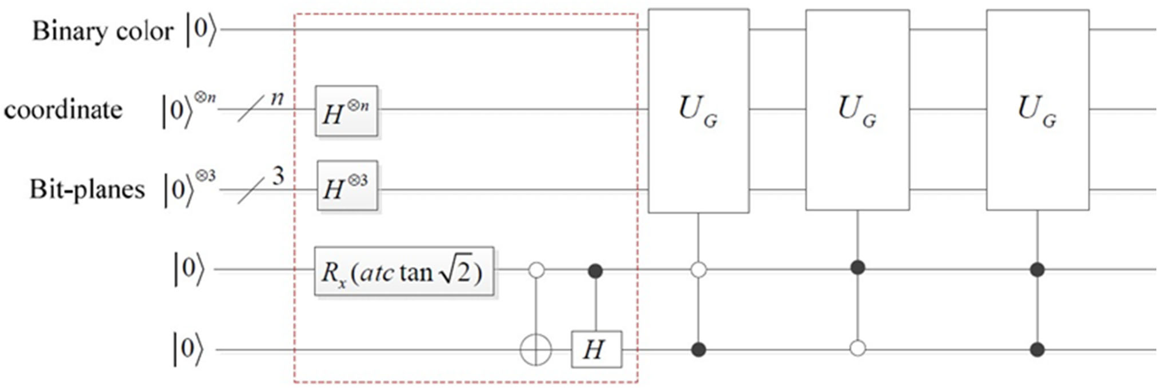
Illustration of the BRQI encoding process in the proposed scheme, formulated based on Equation (14). The circuit initializes spatial and bit-plane quantum registers into superposition states using Hadamard gates. The quantum registers encode pixel values into bit-planes, and the scrambling operators ) apply controlled transformations across the bit-planes. Each bit-plane undergoes a quantum-controlled operation to alter its state while preserving reversibility, ensuring the possibility of perfect decryption.
Figure 3.
Illustration of the BRQI encoding process in the proposed scheme, formulated based on Equation (14). The circuit initializes spatial and bit-plane quantum registers into superposition states using Hadamard gates. The quantum registers encode pixel values into bit-planes, and the scrambling operators ) apply controlled transformations across the bit-planes. Each bit-plane undergoes a quantum-controlled operation to alter its state while preserving reversibility, ensuring the possibility of perfect decryption.
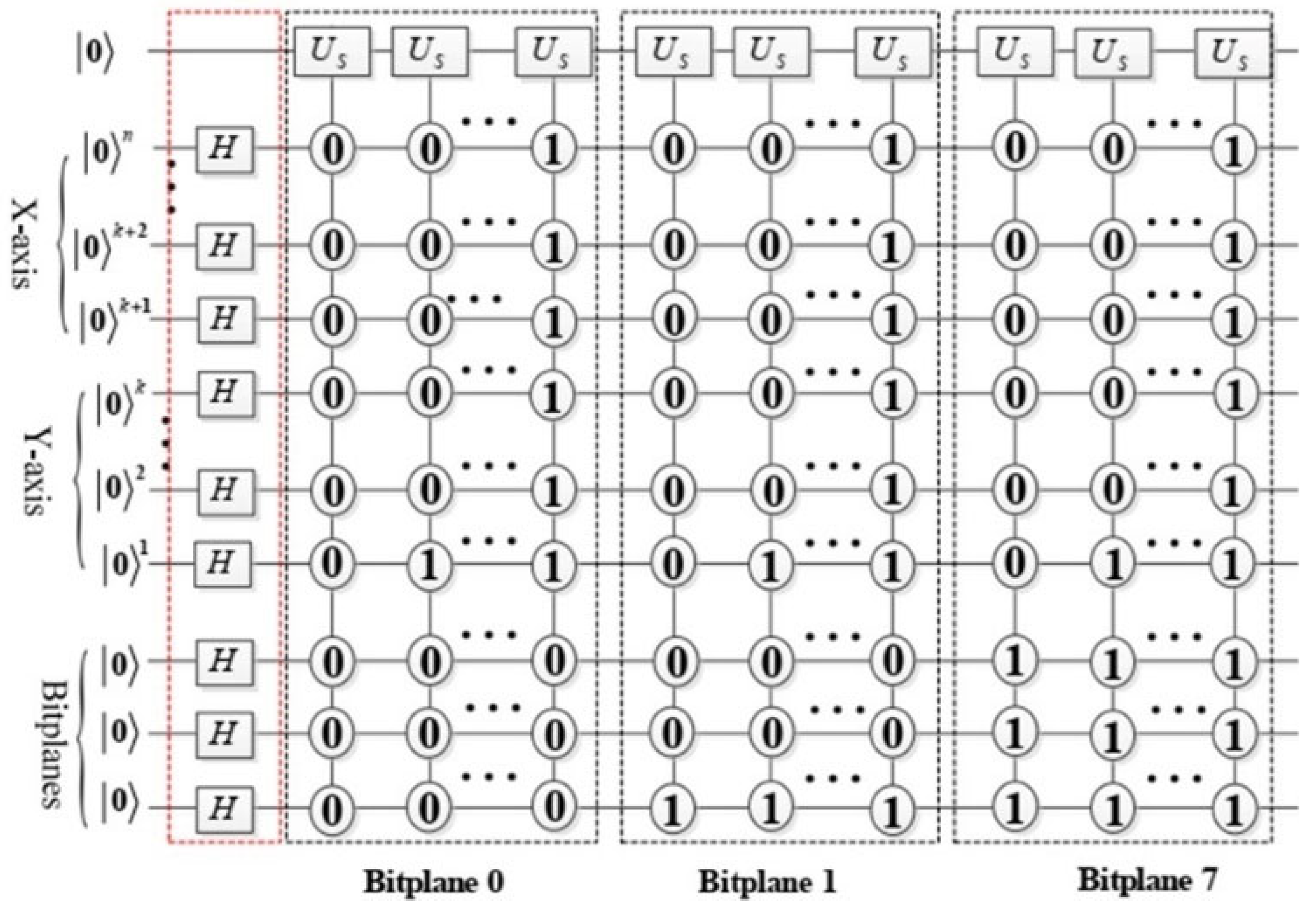
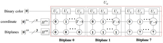
Figure 4.
The BRQI abbreviation sub-circuit designed for grayscale images is represented within the red dashed box, denoted as .
Figure 4.
The BRQI abbreviation sub-circuit designed for grayscale images is represented within the red dashed box, denoted as .
The circuit enclosed within the red dashed box serves to implement as follows.
In this context, and represent the n-fold tensor products of the spaces and , respectively. The circuit depicted within the dashed box corresponding to bit-plane j (where j = 0, 1…, 7) is responsible for storing the j-th bit-plane in quantum systems. Consequently, the circuit , illustrated in Figure 4, is executed.
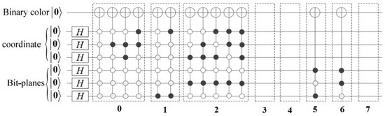
Figure 5.
The circuit design for the implementation of BRQI in the context of grayscale images.
The circuit enclosed within the dashed box labeled l represents the implementation for the l-th bit-plane, denoted as , where j takes on values from 0 to 7. Notably, the pixel values for the 3rd, 4th, and 7th bit-planes are all zero, resulting in the corresponding circuits being inactive. Additionally, since the pixel values for the 5th and 6th bit-planes are both one, their implementation circuits can be streamlined, as illustrated in the dashed boxes 5 and 6. The output generated by the circuit depicted in Figure 5 is as follows:
An RGB color image can be separated into 3 distinct grayscale images, or into 24 individual bit-planes. The color representation for m qubits using a basis state can be articulated in the following manner:
where . For the image on the gray scale is and the color image () is , which is , and .
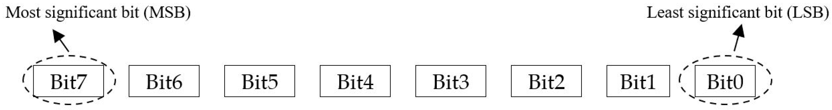
An illustration of the gates is depicted in a color image to explain the BRQI circuit. This research examined the quantum circuit of the BRQI in Figure 6 using color images of , where n + 6 qubits are employed to represent the circuit. The qubits utilized in this system are composed of n qubits dedicated to coordinates, in addition to 6 extra qubits allocated for each pixel in the image. These additional qubits consist of one for binary color, three for bit surfaces, and two for color channel. The gate encompasses both the X-Pauli gate (NOT gate) and the identity gate for binary color. Furthermore, it encompasses the states or for the coordinates and bit-planes that correspond to each image. This comprehensive setup enables the simulation of the image on a quantum circuit.
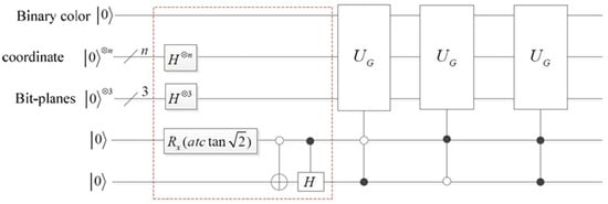
Figure 6.
The circuit implementation of BRQI for RGB color images being discussed.
The representation of is depicted by the red dashed box in Figure 6.
The expression for representing color images of size can be stated as follows:
The given expression states that , , are elements of the set . Additionally, is equal to and is equal to , where and are elements of the set {0,1}. The variable l represents the -th bit-plane [13].
For a 2 2 color image like Figure 7, the states (Quantum states of the red color channel), (Quantum states of the green color channel) and (Quantum states of the blue color channel) can be expressed in accordance with Equation (21), as shown below:
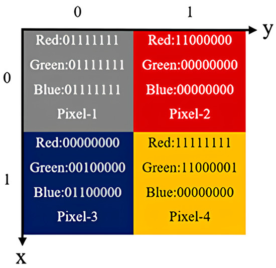
Figure 7.
A 2 × 2 color image.
3.2. Our Model for Rgb Images Encryption Based on Bit-Planes and Logistic Maps
In this section, we describe our proposed quantum image encryption algorithm. Any cryptographic scheme typically consists of three main procedures: key generation, encryption, and decryption. Similar to conventional cryptographic schemes, our proposed method for encrypting RGB images based on bit-planes and logistic maps incorporates all these essential steps. However, for simplicity, we summarize the scheme into two main processes: (1) the scrambling process, which includes both key image generation and the encryption process, and (2) the image reconstruction process.
In the following subsections, we present our proposed quantum image interleaving operation and algorithm, which consist of two main processes: the scrambling process and the image construction process.
3.2.1. Image Scrambling Process
Quantum image scrambling is a process that alters and disrupts the information contained in an image, making it challenging to discern its core patterns and features. In the proposed model, the quantum image scrambling process can be achieved in the following steps:
The original image. The operator acts on the qubits of the bit-planes, resulting in observable changes as described in Equation (23).
- 1.
- Swapping bit-planes.
The first step in the quantum image scrambling process of our proposed model involves swapping bit-planes. During this step, the bit-plane layers of the image are exchanged, causing a random redistribution of the image’s information. This disruption makes it significantly harder to identify the image’s patterns and key features. The aim can be achieved by using a bit-planes swapping operator, which is defined as follows:
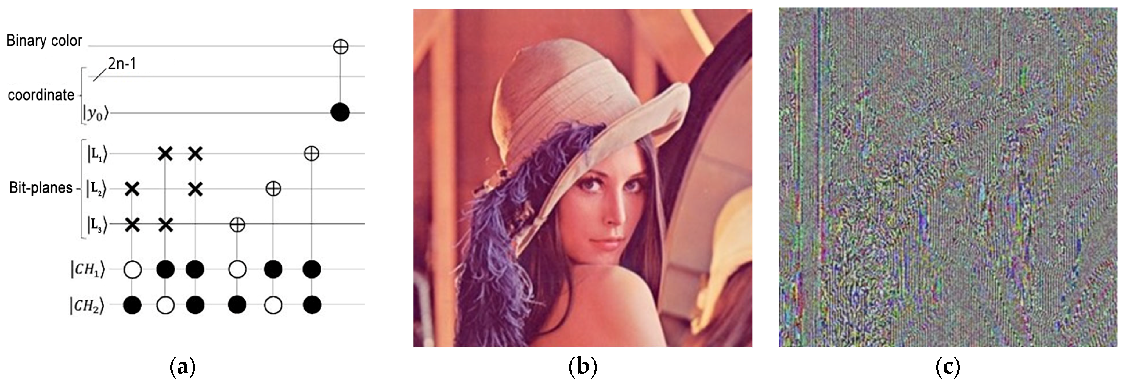
The operator, by affecting the bit-planes of each pixel, causes the bit-planes of the red color channel to move in such a way that the first bit-plane moves with the second bit-plane, and the fifth bit-plane moves with the sixth bit-plane. As shown in the circuit in Figure 8a, for the green color channel, the first bit-plane is moved with the fourth bit-plane, as well as the third bit-plane with the sixth bit-plane, and finally, for the blue color channel, the second bit-plane is moved with the fourth bit-plane. Also, the third bit-plane is moved with the fifth bit-plane, and the effect of this operator on the image in Figure 8b can be seen in a simulated form in Figure 8c. Figure 8a illustrates the impact of this operator on the movement of bit-planes within the red color channel, specifically and . Similarly, in the green color channel, it affects and , while in the blue color channel, it influences and . Additionally, Figure 8 showcases the resulting image after the swapping bit-planes step.
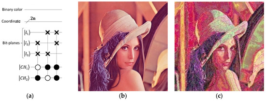
Figure 8.
The process of swapping bit-planes involves the following components: (a) The implementation circuit of , (b) a 256 × 256 color image, and (c) the outcome of the bit-planes swap operation.
- 2.
- Transferring image bit-planes.
The second step in the quantum image scrambling process of our proposed model involves transferring image bit-planes. This step allows for the reassignment of bit-planes to new positions or the creation of entirely new bit-plane configurations. By doing so, it generates new combinations of image bit-planes, further increasing the variability and complexity of the image data. The bit-plane transfer function can be defined as follows:
The operator also moves the bit-planes like the operator, with the difference that all the bit-planes are moved two by two with each other, causing more image pixels to change, as shown in Figure 9c. Using two of the simple quantum gates—the Pauli-X Gate and the identity gate, as shown in the circuit in Figure 9a—the operator is responsible for moving the bit-planes. By moving all the bit-planes at once in a unique way, and pairing them two by two, it distinguishes itself from the bit-planes swap operator. Figure 9 shows the quantum circuit, along with the resulting image under the influence of the transmission image bit-planes process.
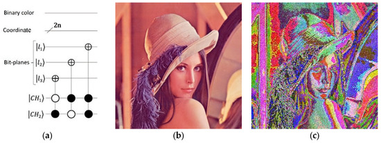
Figure 9.
The process of transferring image bit-planes. (a) The circuit design of . (b) A color image with dimensions of 256 × 256. (c) The outcome of the image bit-planes transfer process.
- 3.
- Color complement.
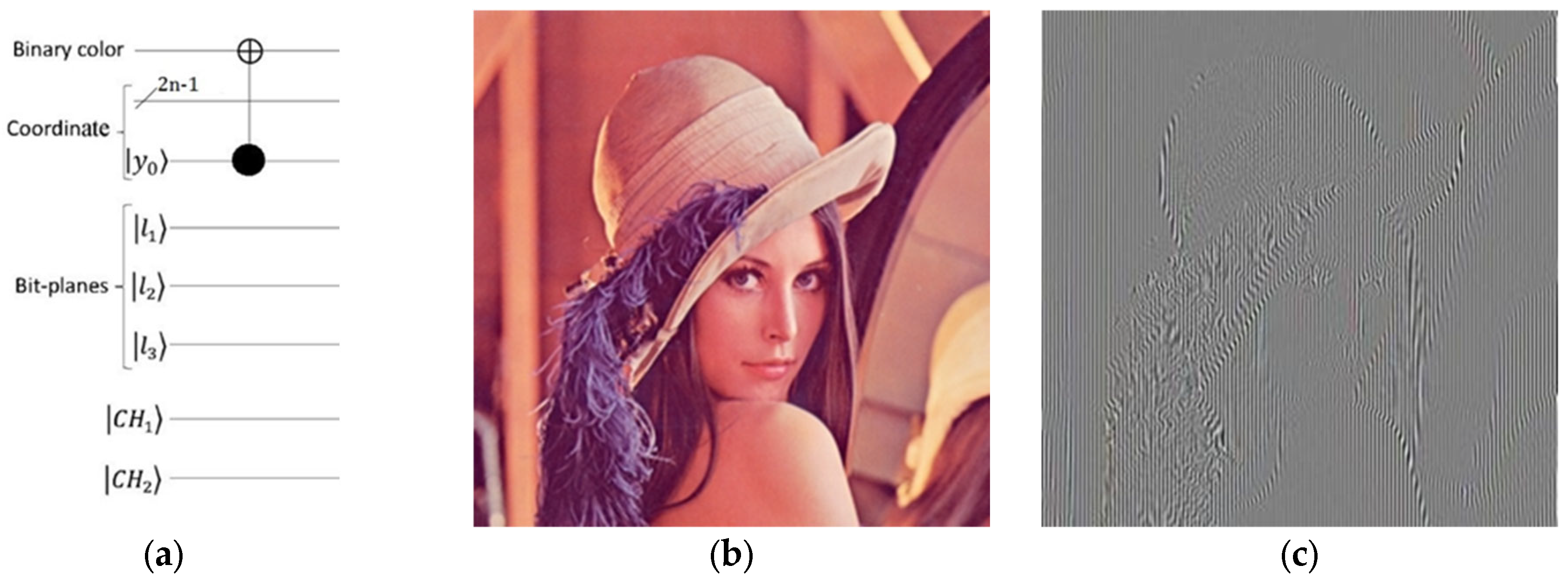
The final step in the quantum image scrambling process of our proposed model is the color complement. By using the color complement process, the colors in the image are reversed. This process alters the image’s colors to complement each other, resulting in visually appealing effects while also enhancing security, which is given by the following operator:
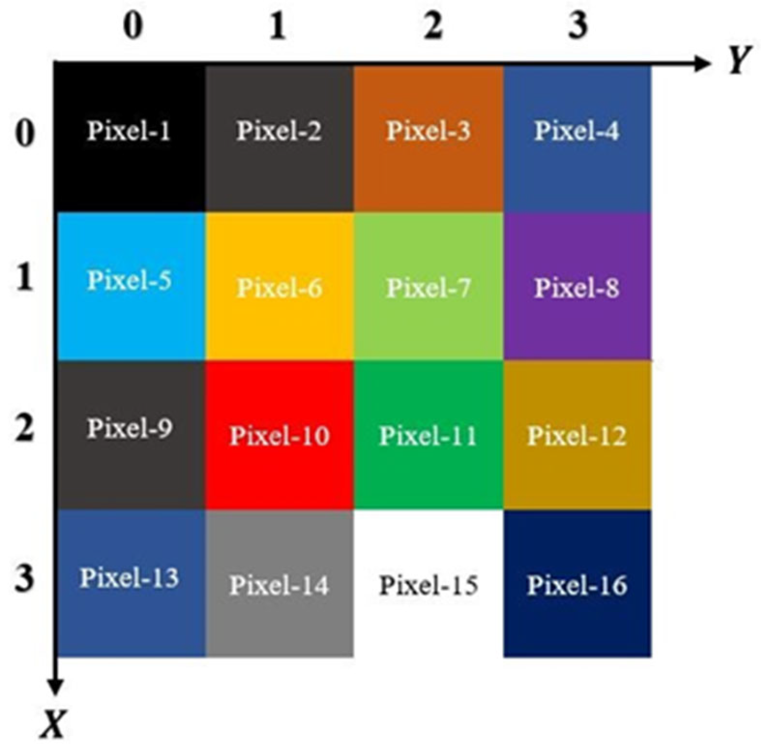
Based on Figure 10, the even-pixels’ coordinates for can be represented in the following manner:
where .

Figure 10.
A 4 × 4 color image with alternating markings on even and odd pixels.
As observed, the Pauli-X gate and identity gate were applied, affecting only the binary color qubit of the even pixels (28). As shown in Figure 10, the even pixels exhibit a unique property. Since x and y correspond to the spatial coordinates of the pixels, by converting the y-coordinate to 2y for odd pixels and 2y + 1 for even pixels, we can easily apply the color complement operator to the even pixels based on the proposed algorithm.
This operator influences the color of all bit-planes for each even pixel in the image. Figure 11 illustrates the results of the first two stages of the scrambling process applied to the Lena image, employing the color complement method from the proposed model.
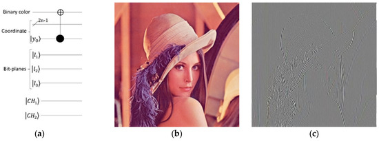
Figure 11.
The functioning of color inversion. (a) The execution circuit of . (b) A 256 × 256 image with colors. (c) The outcome of the color inversion process.
Figure 12a presents the quantum circuit for the initial segment of our encryption algorithm, which focuses on image scrambling. Additionally, Figure 12c displays the simulated output of this first phase of encryption applied to the Lena image. Since our encryption algorithm concludes by merging the image scrambling derived from bit-planes with an image generated using a logistic map of the same dimensions as the original image, we move forward to create an image referred to as the key image, which complicates the recovery of the encrypted image.
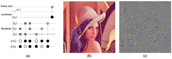
Figure 12.
An image scrambling algorithm that operates on bit-planes. Diagram (a) showcases the implementation circuit of the image scrambling process. In addition, the Lena image is presented in diagram (b). Lastly, diagram (c) demonstrates the encryption of Lena’s image through the utilization of the initial phase algorithm.
- 4.
- Applying logistic map:
Finally, as the last step of our model, we apply the logistic map to the encrypted quantum image. The logistic map is a powerful tool for analyzing complex behavior in dynamical systems. It is a mathematical model based on a recurrence equation that studies the dynamics of nonlinear systems and their chaotic behaviors. Applications of the logistic map extend across various fields, including periodic behavior analysis, chaos theory, artificial intelligence, social sciences, and economics.
The discrete version of the Logistic function is known as the logistic map. As you can see in Equation (29), represents the population in generation t and r is a control parameter that determines the population growth rate. The logistic map is an invertible map; that is, it can be iterated forward in time and reach an from , but the reverse is not possible. This map is also called the iterative mapping function.
Mathematically, for small values of r between 0 and 1, our function exhibits stable behavior, and if this value is between 1 and 3, our function exhibits periodic and oscillating behavior, but if this value is greater than 3, our logistic map becomes chaotic, which we have used here for values in the range [3.569945, 4] to generate a completely random and irregular sequence of numbers [30,31,32,33,34].
In this step, a key image which is used in the final stage of our encryption algorithm is generated. The chaotic numerical sequence produced by the logistic map is transformed into an ordered arrangement of numbers. The generated key image is subsequently combined with the encrypted quantum image using a Binary XOR operation. The logistic map equation [35,36] used for this process is given by:
where r = 3.86 and the initial value x0 = 0.31717115.
The numerical sequence generated by the logistic map is first structured into a 1 × 1,572,864 matrix in MATLAB, where all values are constrained to be less than one. To transform this sequence into a binary representation, each value is rounded to the nearest integer, yielding a binary sequence of 0s and 1s. This binary matrix is then reshaped into an 8-column format with 196,608 rows, where each row represents an 8-bit binary number. By converting these binary numbers into their decimal equivalents, a 196,608 × 1 matrix is obtained. This transformation ensures that the generated sequence aligns with the encrypted quantum image dimensions, forming the foundation for the key image generation process.
To construct the RGB key image, the 196,608 × 1 matrix is further reshaped into a 65,536 × 3 matrix, where each column represents one of the three primary color channels—red, green, and blue. Each of these color channels is then converted into a 256 × 256 matrix, creating three distinct matrices corresponding to the RGB components of the key image. These matrices are then merged to produce the final key image, which serves as a crucial element in the encryption process. The encrypted image from the first phase is combined with this key image using a Binary XOR operation, ensuring the encryption inherits the randomness and unpredictability of the logistic map. The quantum comparator circuit plays a critical role in this final step, ensuring alignment and verification of qubits, coordinates, bit-planes, and color channels. Finally, the Pauli-X gate is applied to the qubits of the encrypted output image, completing the encryption process and generating the final encrypted quantum image. The outcome of this process is visually represented in Figure 12c, Figure 13d and Figure 14b.
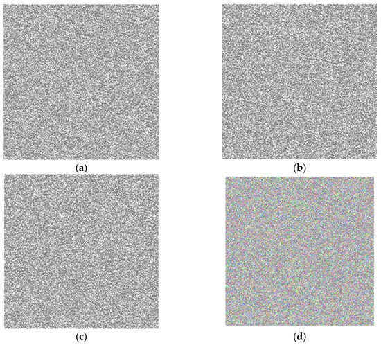
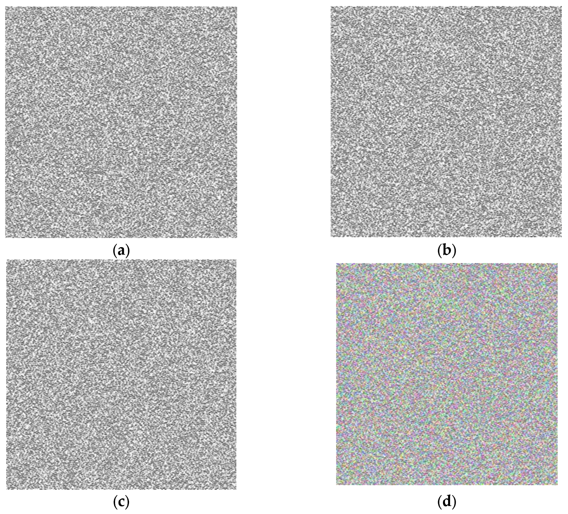
Figure 13.
The key image is formed by utilizing the logistic map equation as its foundation. It comprises four distinct components: (a) the image in the red channel, (b) the image in the green channel, (c) the image in the blue channel, and (d) the outcome of the second stage encryption, which is referred to as the key image.
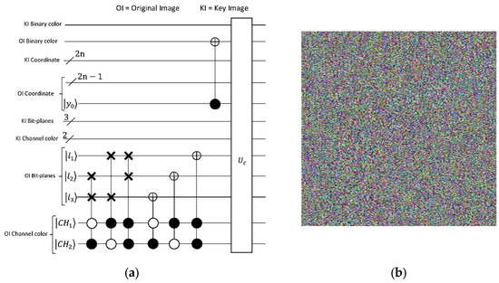
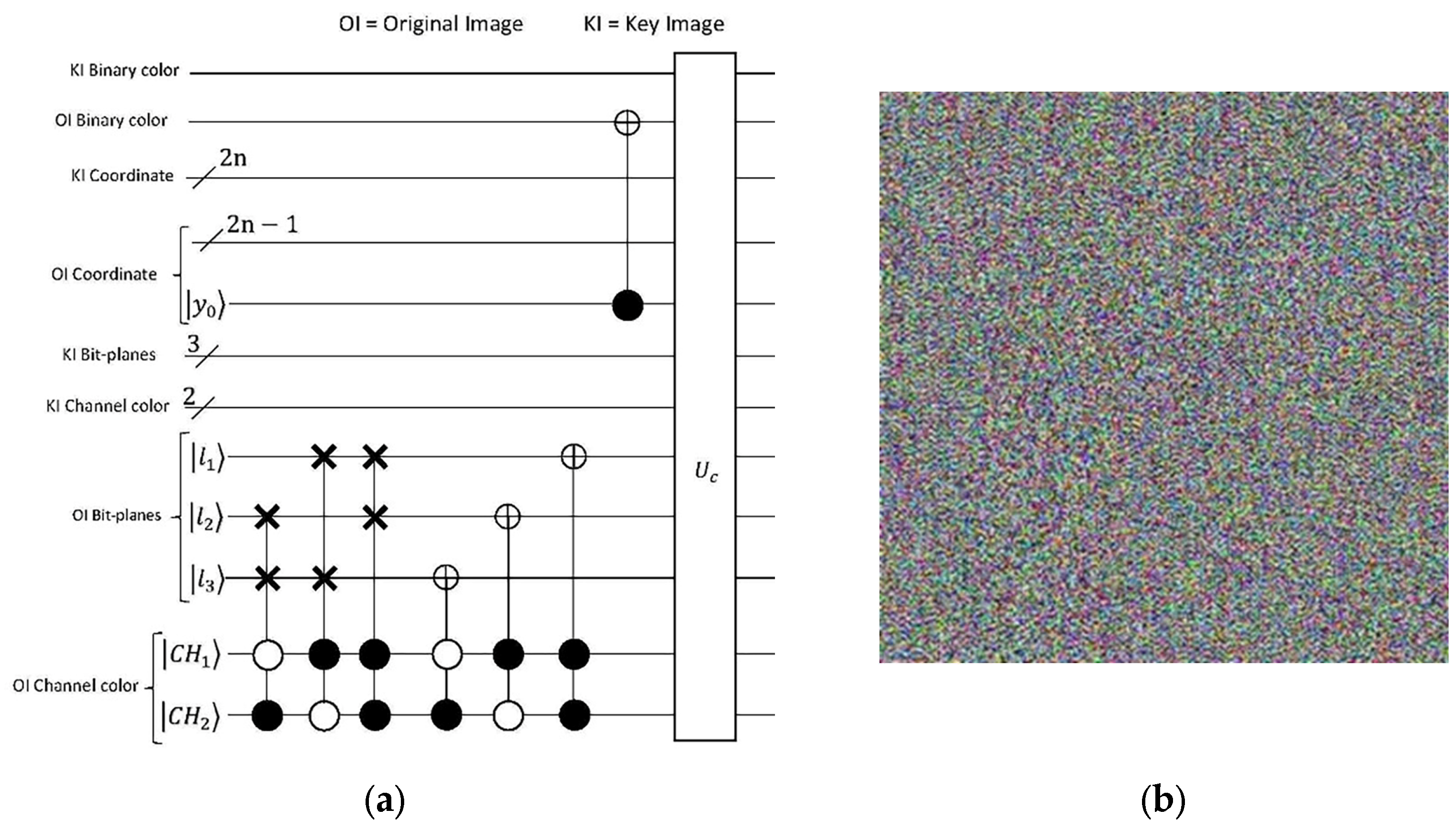
Figure 14.
(a) The circuit for implementing the image scrambling algorithm. (b) The encrypted image after the final processing.
In Figure 14, the complete implementation circuit of the algorithm is presented. The quantum comparator circuit, denoted as in Figure 14, incorporates the Binary XOR (exclusive OR) operation as depicted in Figure 15b. Section V of this study involves the encryption of several images using the aforementioned algorithm, and the outcomes are displayed in Table 4.
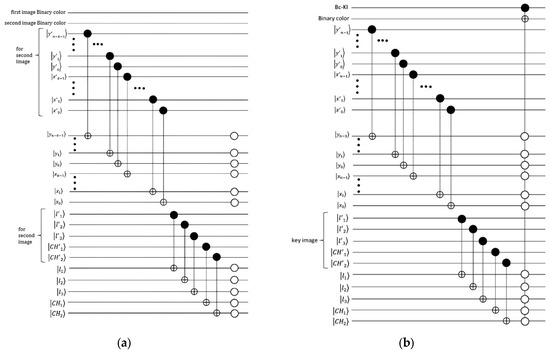
Figure 15.
(a) A quantum comparator circuit for two images of size () utilizing BRQI. (b) A quantum comparator circuit incorporating the Binary XOR (exclusive OR) operation for the key image and the image encrypted by the initial phase algorithm.
Table 4.
Entropy analysis.
3.2.2. Recover Encrypted Image
To recover the original image, or in other words, to decrypt the encrypted image in our proposed algorithm, we must know the steps and encryption algorithm, as well as all the values assumed in the logistic mapping section. First, for decryption, we need to decrypt the image in one step with the key generated by the logistic mapping. Of course, you should be careful to have the same constant values used in the logistic mapping Equation (Equation (29)). The process operates under the XNOR logic gate on the encrypted image. Then, the color complement operator acts on the even pixels so that we can recover its binary color code. After that, we apply the transferring image bit-planes operator based on the circuit in Figure 16a. Considering the orthogonality principle and applying the relevant operator to the desired bit-plane, Equation (25) recursively affects the marked bit-planes. Now, it is time to apply the operator to create the decryption image, or the initial image. This entire process is simulated step by step with the MATLAB program. The encrypted image (Figure 16b) is decrypted (Figure 16c), and the recovery process is completed successfully.
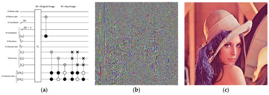
Figure 16.
The image decoding process is shown. The diagram (a) shows the quantum circuit of the image decoding process. (b) Lena’s encrypted image (c) Lena’s decrypted image.
4. Analyzing the Proposed Method
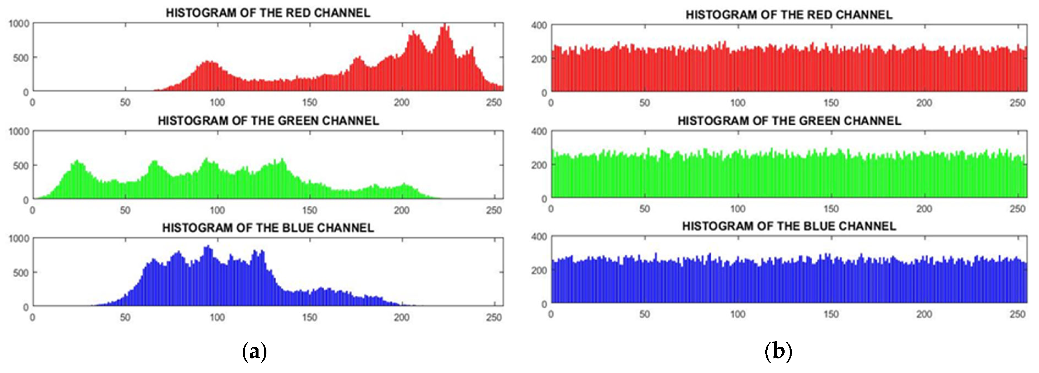
Analyzing the histogram of the algorithm reveals that a smoother peak distribution and a flatter alignment indicate a more effective and efficient image-scrambling process. This is evident in Figure 17, where the histogram of the Lena image is examined. Figure 17a shows the irregular histogram of each color channel in the Lena image before encryption, while Figure 17b depicts the transformation into a smoother and more uniform histogram after encryption using the proposed algorithm.
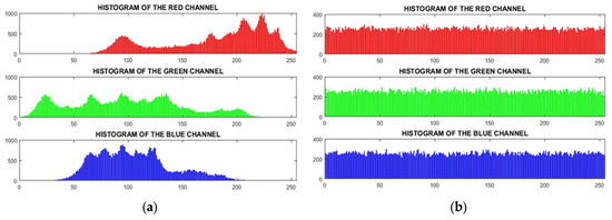
Figure 17.
Histogram: (a) before encryption; (b) after encryption.
Shannon introduced the concept of information entropy in 1949, which has proven to be highly valuable in quantifying randomness within an encryption system. When applied to color images, the Shannon Entropy can be determined by analyzing the probability distribution of pixel intensities. This entropy measurement also serves as an indicator of the image’s irregularity, effectively describing the distribution of gray levels present. A value closer to 8, representing the number of gray levels, signifies the utilization of an encryption algorithm that generates a greater degree of irregularity and random arrangement of pixels [37,38,39]. In Table 4, the entropy of multiple images is compared to evaluate the impact of the encryption algorithm. The results indicate that the proposed algorithm demonstrates notable improvements in both efficiency and effectiveness in scrambling images. The calculations were conducted using the software “Matlab 2016b”. The formula for computing information entropy is presented as follows [40,41].
The probability of the i-th gray level, denoted as , represents the likelihood of that specific gray level occurring. This probability is calculated by normalizing the histogram counts, which takes into account the number of gray levels, denoted as N.
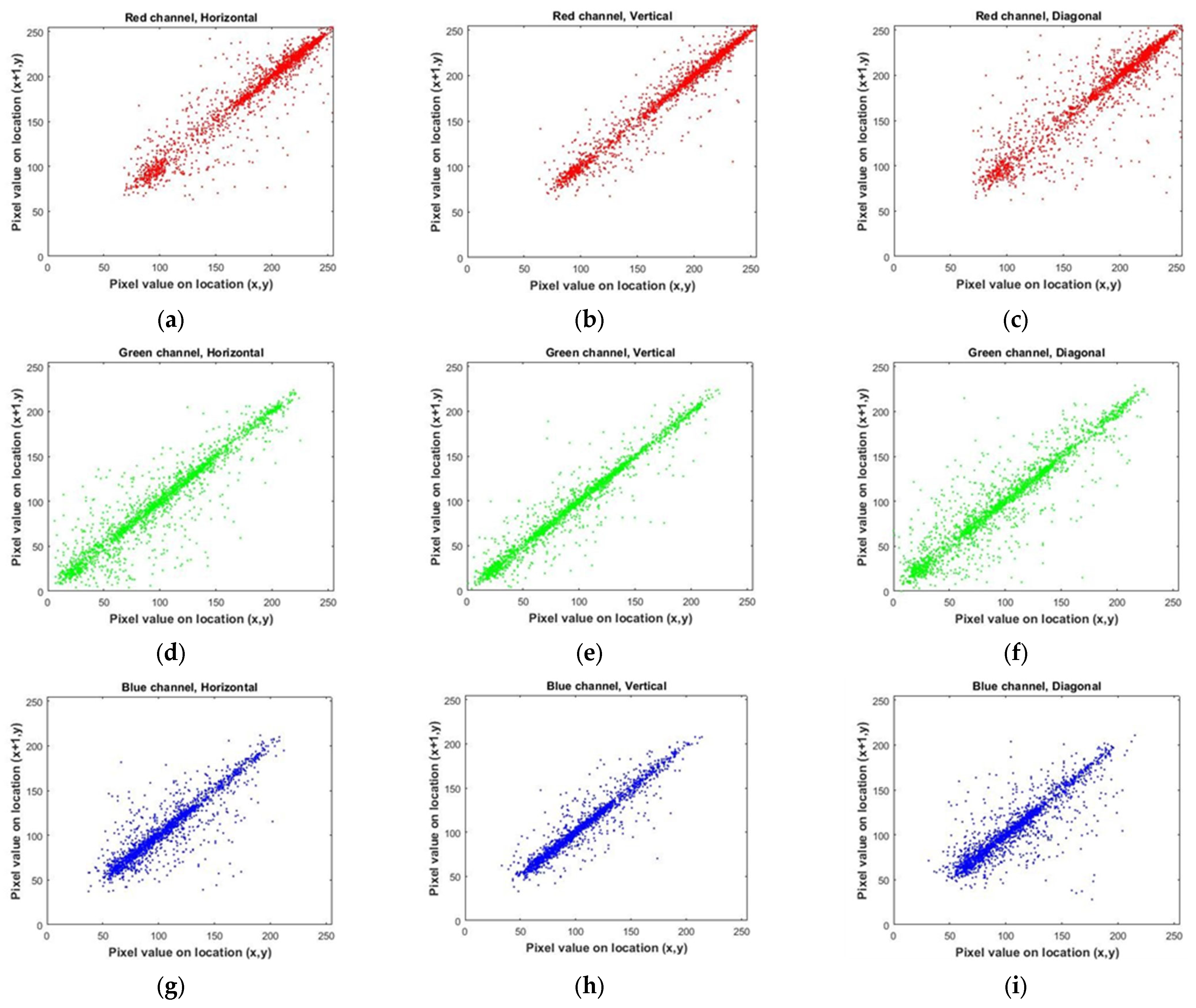
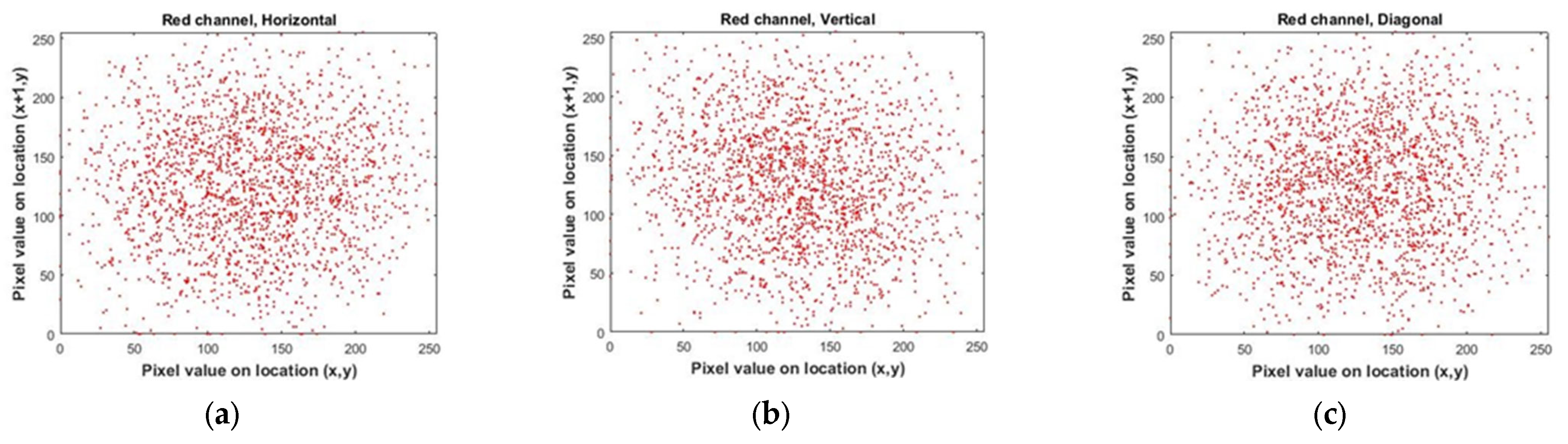
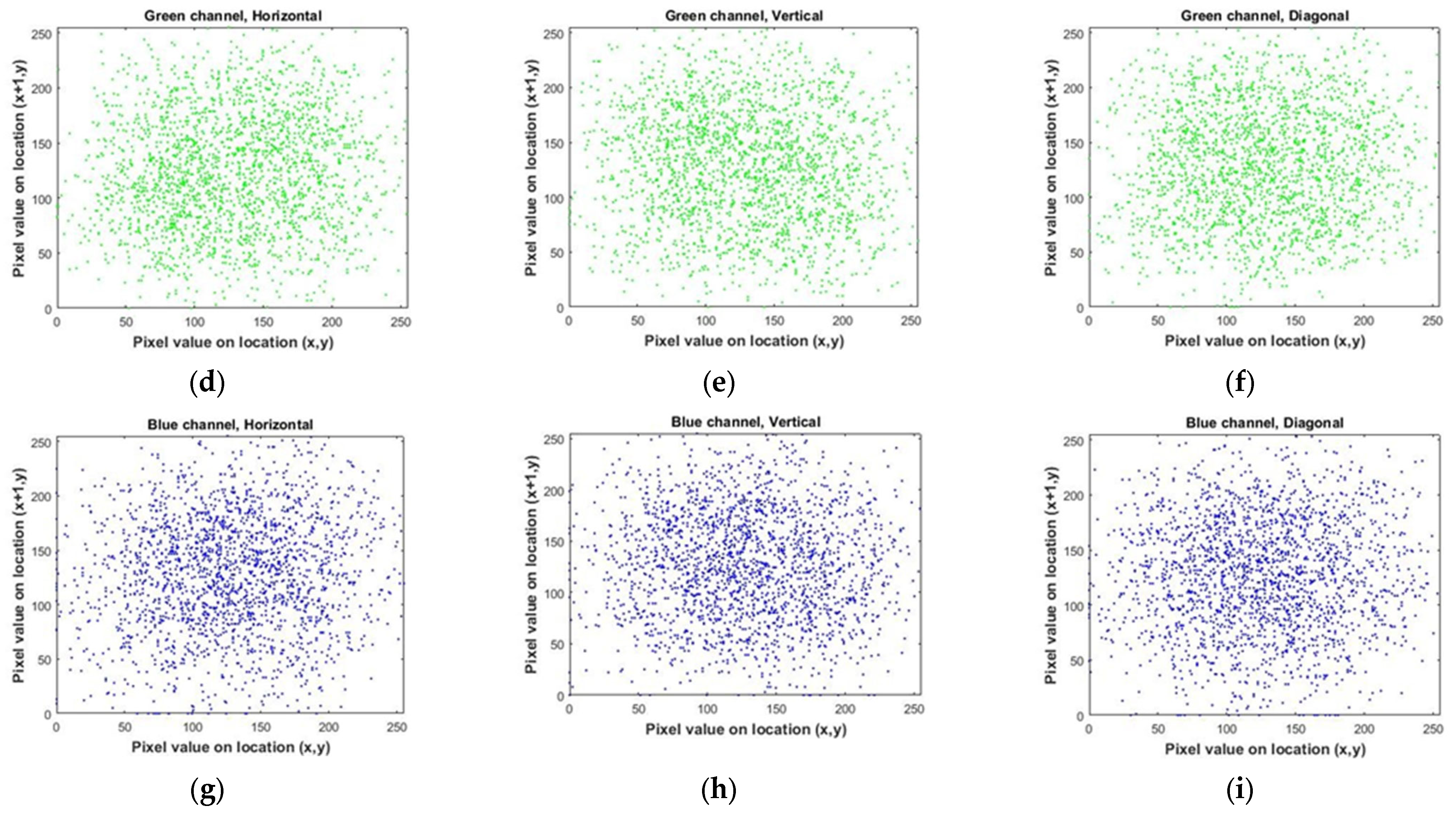
The encryption of an image can be considered highly secure when the correlation coefficient between adjacent pixels is minimized. In order to achieve this, an appropriate encryption algorithm should aim to reduce the correlation coefficient between horizontally, vertically, and diagonally positioned pixels as much as possible. The calculation of the correlation coefficient is performed using a specific Formula (31).
The given expression represents the relationship between the values of two neighboring pixels, denoted as x and y, in an image. The variable N represents the total number of pixels present in the image [41,42,43,44,45].
By conducting a comparative analysis of the correlation coefficient for multiple images in Table 5, both before (for Lena image, Figure 18) and after encryption (for Lena image, Figure 19) using the algorithm under consideration, it becomes evident that the mentioned encryption method provides a high level of security. Also, in Figure 20, you can see a number of images before and after encryption with the proposed algorithm.
Table 5.
Correlation coefficients of plain image and encrypted image.
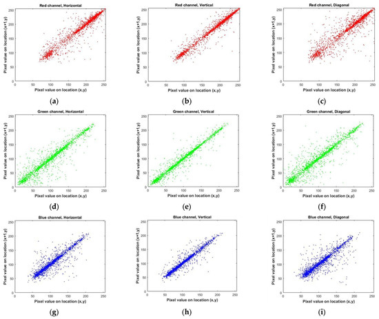
Figure 18.
Correlation distributions of Lena’s image in each direction. (a–c) for the red color channel. (d–f) for the green color channel. (g–i) for the blue color channel.
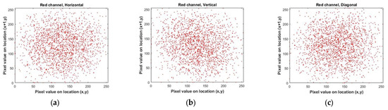
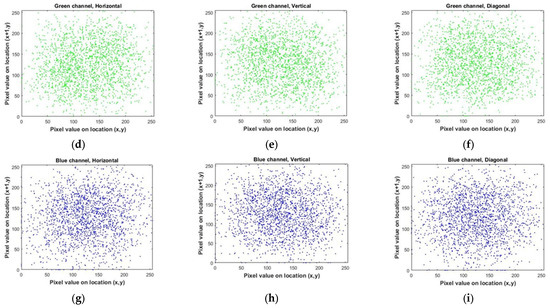
Figure 19.
Correlation distributions of the encrypted Lena image in each direction. (a–c) for the red color channel. (d–f) for the green color channel. (g–i) for the blue color channel.
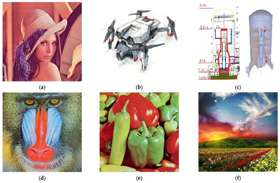
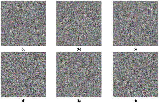
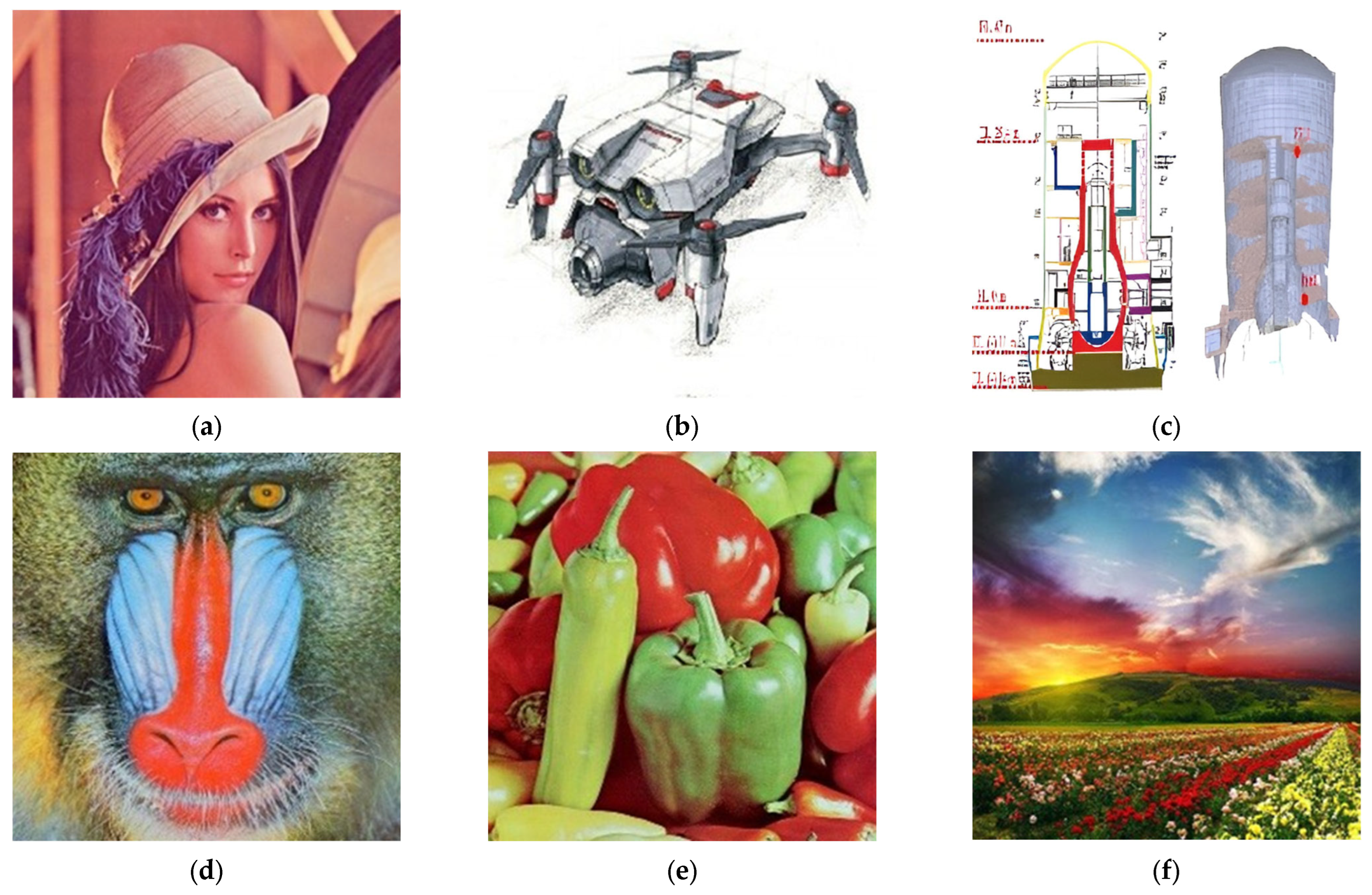
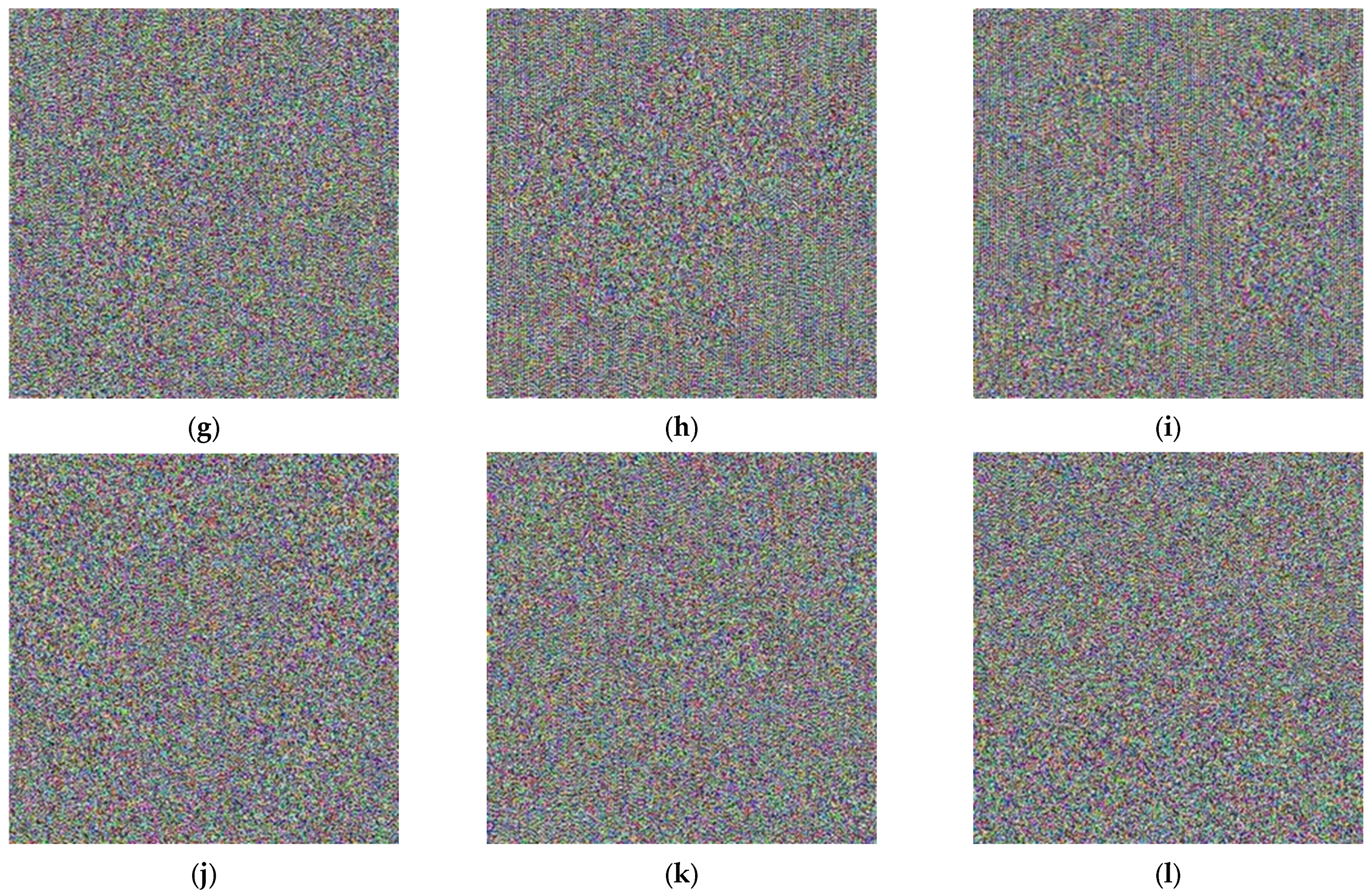
Figure 20.
Multiple images prior to and following the encryption process: (a) Lena; (b) Image-1; (c) Image-2; (d) Image-3; (e) Image-4; (f) Image-5; (g) encrypted Lena; (h) encrypted Image-1; (i) encrypted Image-2; (j) encrypted Image-3; (k) encrypted Image-4; (l) encrypted Image-5.
It is important to note that with knowledge of all the steps of the encryption algorithm, along with access to the key image and its associated variables, one can easily decrypt the encrypted image. Furthermore, the order in which each operator is applied at each stage is critical. By understanding these components, it is sufficient to reverse the process step by step to recover the original image. We successfully restored the original image using the MATLAB program.
5. Conclusions
This paper presents a novel quantum image encryption algorithm aimed at enhancing the security of image transmission and storage. The algorithm operates in two main stages: Color Image Scrambling and the integration of a logistic map. In the first stage, the original quantum image undergoes scrambling using the Bit-plane Swap Operator, Image Bit-plane Transfer Operator, and color complement operator, ensuring effective disruption of the image’s original structure. An image called the key image is created in the second part, the construction process, which is a chaotic sequence created by the logistic map. Then, the two images resulting from the image scrambling process and the construction process by the quantum comparator are the output of our encryption algorithm. This combination leverages the principles of quantum mechanics and chaos theory, offering robust security superior to classical methods. The security of the proposed algorithm is further reinforced against potential quantum threats, such as quantum cloning machines, due to the inherent randomness and sensitivity of chaotic systems. Various metrics are employed to evaluate its effectiveness, including histograms, entropy, and correlation coefficients. Post-encryption histograms display a uniform distribution of color spectrums, effectively mitigating the risk of statistical attacks and safeguarding the original image. Correlation analyses reveal a significant reduction in pixel dependency, demonstrating the algorithm’s ability to disrupt spatial patterns. The entropy of the Lena image, recorded at approximately 7.75 before encryption, reaches the ideal maximum of 8 after applying the algorithm, indicating highly secure encryption. This pattern is consistent across multiple test images. Additionally, the correlation distributions analyzed in three directions for neighboring pixels confirm the algorithm’s capability to achieve spatial independence after encryption. These findings strongly support the exceptional performance of the proposed quantum encryption algorithm, demonstrating its effectiveness, efficiency, and heightened security in comparison to existing methods. This work represents a significant step forward in leveraging quantum computing for advanced image encryption.
Author Contributions
Conceptualization, L.F.M. and M.N.; data curation, S.B., L.F.M. and M.N.; formal analysis, S.B., L.F.M. and M.N.; investigation, S.B., L.F.M. and M.N.; methodology, S.B., L.F.M. and M.N.; resources, S.B., L.F.M. and M.N.; software, S.B.; supervision, L.F.M. and M.N.; validation, S.B., L.F.M. and M.N.; writing—original draft, S.B., L.F.M. and M.N.; writing—review and editing, S.B., L.F.M. and M.N. All authors have read and agreed to the published version of the manuscript.
Funding
This research received no external funding.
Data Availability Statement
Data are contained within the article.
Acknowledgments
The first and second authors thank Islamic Azad University for supporting this research.
Conflicts of Interest
The authors declare no conflicts of interest.
References
- Morkel, T.; Eloff, .H.; Olivier, M.S. An Overview of Image Steganography. In Information Security South Africa; University of Pretoria: Pretoria, South Africa, 2005; pp. 1–11. [Google Scholar]
- Pahati, O.J. Confounding Carnivore: How to Protect Your Online Privacy. AlterNet 2001, 7–16. [Google Scholar]
- Singh, L.D.; Singh, K.M. Image Encryption Using Elliptic Curve Cryptography. Procedia Comput. Sci. 2015, 54, 287–294. [Google Scholar] [CrossRef]
- Lukac, R.; Plataniotis, K.N. Bit-Level-Based Secret Sharing for Image Encryption. Pattern Recognit. 2005, 38, 873–882. [Google Scholar] [CrossRef]
- Mishra, R.; Bhanodiya, P. A review on steganography and cryptography. In Proceedings of the 2015 International Conference on Advances in Computer Engineering and Applications, Ghaziabad, India, 19–20 March 2015; pp. 119–122. [Google Scholar] [CrossRef]
- Kamali, S.H.; Shakerian, R.; Hedayati, M.; Rahmani, M. A New Modified Version of Advanced Encryption Standard Based Algorithm for Image Encryption. In Proceedings of the International Conference on Electronics and Information Engineering, Kyoto, Japan, 1–3 August 2010. [Google Scholar]
- Jiang, N.; Wang, L.; Wu, W. Quantum Hilbert Image Scrambling. Int. J. Theor. Phys. 2014, 53, 2655–2663. [Google Scholar] [CrossRef]
- Jiang, N.; Wu, W.; Wang, L. The Quantum Realization of Arnold and Fibonacci Image Scrambling. Quantum Inf. Process. 2014, 13, 2179–2192. [Google Scholar] [CrossRef]
- Sankpal, P.R.; Vijaya, P.A. Image Encryption Using Chaotic Maps: A Survey. In Proceedings of the Fifth International Conference on Signal and Image Processing, Bangalore, India, 8–10 January 2014. [Google Scholar]
- Chen, J.X.; Zhu, Z.L.; Liu, Z.; Fu, C.; Zhang, L.B.; Yu, H. A Novel Double-Image Encryption Scheme Based on Cross-Image Pixel Scrambling in Gyrator Domains. Opt. Express 2014, 22, 10343–10356. [Google Scholar] [CrossRef] [PubMed]
- Wong, K.W.; Kwok, B.S.H.; Yuen, C.H. An Efficient Diffusion Approach for Chaos-Based Image Encryption. Chaos Solitons Fractals 2009, 42, 1877–1888. [Google Scholar] [CrossRef]
- Yang, Y.; Jia, X.; Xu, P.; Tian, J. Analysis and Improvement of the Watermark Strategy for Quantum Images Based on Quantum Fourier Transform. Quantum Inf. Process. 2013, 12, 2971–2990. [Google Scholar] [CrossRef]
- Li, H.; Chen, X.; Xia, H.; Liang, Y.; Zhou, Z. A Quantum Image Representation Based on Bitplanes. Proc. IEEE 2018, 6, 62396–62404. [Google Scholar] [CrossRef]
- Yan, F.; Iliyasu, A.M.; Venegas-Andraca, S.E. A Survey of Quantum Image Representations. Quantum Inf. Process. 2016, 15, 1065–1085. [Google Scholar] [CrossRef]
- Erhard, M.; Krenn, M.; Zeilinger, A. Advances in High-Dimensional Quantum Entanglement. Nat. Rev. Phys. 2020, 2, 365–381. [Google Scholar] [CrossRef]
- Vedral, V. Quantum Entanglement. Nat. Phys. 2014, 10, 256–258. [Google Scholar] [CrossRef]
- Delaubert, V.; Treps, N.; Fabre, C.; Bachor, H.A.; Réfrégier, P. Quantum Limits in Image Processing. EPL (Europhys. Lett.) 2008, 81, 44001. [Google Scholar] [CrossRef]
- Venegas-Andraca, S.E.; Bose, S. Storing, Processing, and Retrieving an Image Using Quantum Mechanics. In Quantum Information and Computation; SPIE: Bellingham, DC, USA, 2003; Volume 5105, pp. 137–147. [Google Scholar]
- Chakraborty, S.; Mandal, S.B.; Shaikh, S.H. Quantum Image Processing: Challenges and Future Research Issues. Int. J. Inf. Technol. 2018, 10, 475–489. [Google Scholar] [CrossRef]
- Ventura, D.; Martinez, T. Quantum Associative Memory with Exponential Capacity. In Proceedings of the IEEE International Joint Conference on Neural Networks, World Congress on Computational Intelligence, Anchorage, AK, USA, 4–9 May 1998; Volume 1, pp. 509–513. [Google Scholar]
- Le, P.Q.; Dong, F.; Hirota, K. A Flexible Representation of Quantum Images for Polynomial Preparation, Image Compression, and Processing Operations. Quantum Inf. Process. 2011, 10, 63–84. [Google Scholar] [CrossRef]
- Li, H.S.; Zhu, Q.; Li, M.C.; Ian, H. Multidimensional color image storage, retrieval, and compression based on quantum amplitudes and phases. Inf. Sci. 2014, 273, 212–232. [Google Scholar] [CrossRef]
- Sun, B.; Iliyasu, A.M.; Yan, F.; Dong, F.; Hirota, K. An RGB Multi-Channel Representation for Images on Quantum Computers. J. Adv. Comput. Intell. Intell. Inform. 2013, 17, 404–417. [Google Scholar] [CrossRef]
- Zhang, Y.; Lu, K.; Gao, Y.; Wang, M. NEQR: A Novel Enhanced Quantum Representation of Digital Images. Quantum Inf. Process. 2013, 12, 2833–2860. [Google Scholar] [CrossRef]
- Abdolmaleky, M.; Naseri, M.; Batle, J.; Farouk, A.; Gong, L.-H. Red-Green-Blue multi-channel quantum representation of digital images. Optik 2017, 128, 121–132. [Google Scholar] [CrossRef]
- Li, H.S.; Fan, P.; Xia, H.Y.; Peng, H.; Song, S. Quantum Implementation Circuits of Quantum Signal Representation and Type Conversion. IEEE Trans. Circuits Syst. I Regul. Pap. 2018, 65, 341–354. [Google Scholar] [CrossRef]
- Heidari, S.; Naseri, M. A Novel LSB Based Quantum Watermarking. Int. J. Theor. Phys. 2016, 55, 4205–4218. [Google Scholar] [CrossRef]
- Naseri, M.; Heidari, S.; Baghfalaki, M.; Fatahi, N.; Gheibi, R.; Batle, J.; Farouk, A.; Habibi, A. A new secure quantum watermarking scheme. Optik 2017, 139, 77–86. [Google Scholar] [CrossRef]
- U.S. District Court Rules in Favor of Copyright Protection for Standards Incorporated by Reference into Federal Regulations. Available online: www.ansi.org (accessed on 24 November 2017).
- Zhang, L.; Liao, X.; Wang, X. An Image Encryption Approach Based on Chaotic Maps. Inf. Sci. 2005, 24, 237–245. [Google Scholar] [CrossRef]
- Fridrich, J. Image Encryption Based on Chaotic Maps. In Proceedings of the IEEE International Conference on Systems, Man, and Cybernetics, Orlando, FL, USA, 12–15 October 1997; pp. 1105–1110. [Google Scholar]
- Peng, J.; Jin, S.; Chen, G.; Yang, Z.; Liao, X. An Image Encryption Scheme Based on Chaotic Map. In Proceedings of the 2008 Fourth International Conference on Natural Computation, Jinan, China, 18–20 October 2008; pp. 595–599. [Google Scholar] [CrossRef]
- Jakobson, M.V. Absolutely Continuous Invariant Measures for One-Parameter Families of One-Dimensional Maps. Commun. Math. Phys. 1981, 81, 39–88. [Google Scholar] [CrossRef]
- Kwok, H.S.; Tang, W.K.S. A Fast Image Encryption System Based on Chaotic Maps with Finite Precision Representation. Chaos Solitons Fractals 2007, 33, 1919–1928. [Google Scholar] [CrossRef]
- May, R.M. Simple Mathematical Models with Very Complicated Dynamics. Nature 1976, 261, 459–467. [Google Scholar] [CrossRef] [PubMed]
- Pareek, N.K.; Patidar, V.; Sud, K.K. Image Encryption Using Chaotic Logistic Map. Image Vis. Comput. 2006, 24, 926–934. [Google Scholar] [CrossRef]
- Thum, C. Measurement of the Entropy of an Image with Application to Image Focusing. IEEE Trans. Pattern Anal. Mach. Intell. 1984, 31, 203–211. [Google Scholar] [CrossRef]
- Wu, X.; Wang, K.; Wang, X.; Kan, H. Lossless Chaotic Color Image Cryptosystem Based on DNA Encryption and Entropy. Nonlinear Dyn. 2017, 87, 855–875. [Google Scholar] [CrossRef]
- Cheng, H.D.; Jiang, X.H.; Wang, J. Color Image Segmentation Based on Histogram Thresholding and Region Merging. Pattern Recognit. 2002, 35, 373–393. [Google Scholar] [CrossRef]
- Wu, Y.; Zhou, Y.; Saveriades, G.; Agaian, S.; Noonan, J.P.; Natarajan, P. Local Shannon Entropy Measure with Statistical Tests for Image Randomness. Inf. Sci. 2013, 222, 323–342. [Google Scholar] [CrossRef]
- Shannon, C.E. A Mathematical Theory of Communication. Bell Syst. Tech. J. 1948, 27, 379–423. [Google Scholar] [CrossRef]
- Pisarchik, A.N.; Zanin, M. Image Encryption with Chaotically Coupled Chaotic Maps. Phys. D Nonlinear Phenom. 2008, 237, 2638–2648. [Google Scholar] [CrossRef]
- Rhouma, R.; Meherzi, S.; Belghith, S. OCML-Based Colour Image Encryption. Inf. Sci. 2009, 40, 309–318. [Google Scholar] [CrossRef]
- Mackenzie, C.E. Coded Character Sets: Overview of Image Steganography, 1st ed.; The Systems Programming Series; Addison-Wesley Publishing Company, Inc.: Boston, MA, USA, 1980. [Google Scholar]
- Abdullah, A.H.; Enayatifar, R.; Lee, M. A Hybrid Genetic Algorithm and Chaotic Function Model for Image Encryption. Appl. Math. Comput. 2012, 66, 185–198. [Google Scholar] [CrossRef]


Disclaimer/Publisher’s Note: The statements, opinions and data contained in all publications are solely those of the individual author(s) and contributor(s) and not of MDPI and/or the editor(s). MDPI and/or the editor(s) disclaim responsibility for any injury to people or property resulting from any ideas, methods, instructions or products referred to in the content. |
© 2025 by the authors. Licensee MDPI, Basel, Switzerland. This article is an open access article distributed under the terms and conditions of the Creative Commons Attribution (CC BY) license (https://creativecommons.org/licenses/by/4.0/).